RCWP5100MKMWB中文资料
埃森平台 MW 系列微型电路保护器说明书

Protective Devices Miniature Circuit Breakers PLN4Catalog1.11EATON CORPORATION CA019074ENProtective DevicesMiniature Circuit Breakers PLN4 (MW)• T op-quality miniature circuit breakers 1P+N with a width of 1 module unit requiring little space for installation• Contact position indicator red - green • Guide for secure terminal connection • C omprehensive range of accessories can be mounted subsequently • Rated currents up to 40 A • Tripping characteristics B, C• R ated breaking capacity 4.5 kA according to IEC/EN 60898-1DescriptionSG157112EATON CORPORATION CA019074EN 3EATON CORPORATION CA019074ENSpecifications | Miniature Circuit Breakers PLN6, PLN4Description• High selectivity between MCB and back-up fuse due to low let-through energy • B usbar positioning optionally above or below • Compatible with standard busbar• Switching toggle in colour designating the rated current • M eets the requirements of insulation co-ordination, distance between con-tacts ³ 4 mm, for secure isolation • 1-pole breaking capacityI cn 1 = 3 kA Accessories:Auxiliary switch for subsequent installation ZP-IHK 286052ZP-WHK 286053Tripping signal switch for subsequent installation ZP-NHK 248437Remote control and automatic switching device Z-FW/LP 248296Shunt trip release ZP-ASA/..248438, 248439Undervoltage releaseZ-USA/..248288-248291Busbars:see capter busbar systemsTechnical DataPLN6, PLN4ElectricalDesign according toCurrent test marks as printed onto the device IEC/EN 60898-1Rated voltage U n 230 VAC Rated frequency50/60 Hz Rated breaking capacity according to IEC/EN 60898-1I cnPLN6 6 kA PLN4 4.5 kA Characteristic B, CBack-up fuse>6 kA max. 100 A gL/gG >4.5 kA max. 80 A gL/gG Selectivity class3Endurance electrical components ³ 8,000 switching operationsMechanical Frame size 45 mm Device height 80 mmDevice width 17.5 mm (1MU for 1+N)Mountingquick fastening with 2 lock-in positions on DIN rail IEC/EN 60715Degree of protectionIP20Upper and lower terminals open-mouthed/lift terminalsTerminal protection finger and hand touch safe, DGUV VS3, EN 50274Terminal capacity1-16 mm 2Connection diagram1+N-poleDimensions (mm)Rated current I n (A)TypeDesignationArticle No.Units per package4.5 kA, Characteristic BSG157116PLN4-B6/1N 26317912/12010PLN4-B10/1N 26318012/12013PLN4-B13/1N 26318112/12016PLN4-B16/1N 26318212/12020PLN4-B20/1N 26318312/12025PLN4-B25/1N 26318412/12032PLN4-B32/1N 26318512/12040PLN4-B40/1N26318612/1201+N-pole4.5 kA, Characteristic CSG157116PLN4-C6/1N 26318912/12010PLN4-C10/1N 26319012/12013PLN4-C13/1N 26319112/12016PLN4-C16/1N 26319212/12020PLN4-C20/1N 26319312/12025PLN4-C25/1N 26319412/12032PLN4-C32/1N 26319512/12040PLN4-C40/1N26319612/1201+N-pole Explanation PLN4:P = xPole , LN = Miniature Circuit Breakers 1P+N, 1MU , 4 = 4.5 kA4EATON CORPORATION CA019074EN5EATON CORPORATION CA019074ENShort-circuit Selectivity PLN4In case of short-circuit, there is selectivity between the miniature circuit breakers PLN4 and the upstream fuses up to the specified values of the selectivity limit current I s [kA] (i. e. in case of short-circuit currents I ks under I s only the MCB will trip, in case of short-circuit currents above this value both protective devices will respond).*) basically in accordance with EN 60898-1 D.5.2.bShort-circuit selectivity Characteristic B towards fuse link DII-DIV *)Short-circuit selectivity Characteristic C towards fuse link DII-DIV *)PLN4DII-DIV gL/gG I n [A]20253550638010060.7 1.2 2.9 4.52) 4.52) 4.52) 4.52)100.60.9 1.9 3.1 4.52) 4.52) 4.52)130.50.7 1.5 2.5 4.52) 4.52) 4.52)160.50.7 1.4 2.3 4.3 4.52) 4.52)200.50.7 1.4 2.2 4.0 4.52) 4.52)250.50.6 1.3 2.0 3.8 4.52) 4.52)320.50.6 1.2 1.8 3.4 4.52) 4.52)40<0.51)0.61.1 1.7 3.1 4.52) 4.52)Short-circuit selectivity Characteristic B towards fuse link D01-D03*)Short-circuit selectivity Characteristic C towards fuse link D01-D03*)PLN4DII-DIV gL/gG I n [A]2025355063801002 1.5 3.8 4.52) 4.52) 4.52) 4.52) 4.52)40.7 1.2 3.3 4.52) 4.52) 4.52) 4.52)60.7 1.1 2.6 4.52) 4.52) 4.52) 4.52)100.50.8 1.7 2.8 4.52) 4.52) 4.52)130.50.7 1.5 2.5 4.52) 4.52) 4.52)160.50.6 1.2 2.0 3.6 4.52) 4.52)200.50.61.2 1.8 3.3 4.52) 4.52)25<0.51)0.6 1.1 1.7 3.0 4.52) 4.52)32<0.51)0.6 1.0 1.6 2.8 4.52) 4.52)40<0.51)0.6 1.0 1.5 2.6 4.0 4.52)PLN4D01-D03 gL/gG I n [A]20253550638010060.60.9 2.5 4.52) 4.52) 4.52) 4.52)100.50.8 1.6 3.4 4.52) 4.52) 4.52)130.50.7 1.3 2.7 4.0 4.52) 4.52)160.50.6 1.3 2.5 3.8 4.52) 4.52)20<0.51)0.61.32.43.64.52) 4.52)25<0.51)0.6 1.2 2.3 3.3 4.52) 4.52)32<0.51)0.6 1.1 2.1 3.0 4.52) 4.52)40<0.51)0.6 1.0 2.0 2.8 4.52) 4.52)PLN4D01-D03 gL/gG I n [A]2025355063801002 1.1 2.0 4.52) 4.52) 4.52) 4.52) 4.52)40.60.9 2.7 4.52) 4.52) 4.52) 4.52)60.60.9 2.3 4.52) 4.52) 4.52) 4.52)100.50.7 1.5 3.0 4.52) 4.52) 4.52)130.50.71.32.7 4.0 4.52) 4.52)16<0.51)0.6 1.1 2.23.14.52) 4.52)20<0.51)0.6 1.1 2.1 2.9 4.52) 4.52)25<0.51)0.5 1.0 2.0 2.7 4.52) 4.52)32<0.51)0.5 1.0 1.9 2.6 4.52) 4.52)40<0.51)0.50.9 1.7 2.3 4.0 4.52)1) Selectivity limit current I sunder 0.5 kA2) S electivity limit current I s = rated breaking capacity I cn of the MCBShort-circuit selectivity Characteristic B towards fuse link NH-00*)Short-circuit selectivity Characteristic C towards fuse link NH-00*)PLN4NH-00 gL/gG I n [A]202532354050638010060.50.91.52.33.24.52) 4.52) 4.52) 4.52)10<0.51)0.7 1.2 1.5 2.0 3.1 3.9 4.52) 4.52)13<0.51)0.6 1.0 1.3 1.7 2.5 3.1 4.52) 4.52)16<0.51)0.6 1.0 1.3 1.6 2.4 2.9 4.52) 4.52)20<0.51)0.50.9 1.3 1.5 2.3 2.8 4.3 4.52)25<0.51)0.50.9 1.1 1.4 2.1 2.6 4.0 4.52)32<0.51)0.50.8 1.0 1.3 1.9 2.4 3.6 4.52)40<0.51)0.50.80.9 1.1 1.7 2.2 3.3 4.52)PLN4NH-00 gL/gG I n [A]202532354050638010020.7 2.1 4.52) 4.52) 4.52) 4.52) 4.52) 4.52) 4.52)40.50.9 1.6 2.6 3.7 4.52) 4.52) 4.52) 4.52)60.50.8 1.4 2.1 2.9 4.52) 4.52) 4.52) 4.52)10<0.51)0.6 1.0 1.4 1.9 2.8 3.5 4.52) 4.52)13<0.51)0.60.9 1.3 1.7 2.5 3.1 4.52) 4.52)16<0.51)0.50.7 1.0 1.3 2.0 2.5 3.8 4.52)20<0.51)0.50.70.9 1.2 1.8 2.3 3.5 4.52)25<0.51)0.50.70.9 1.1 1.6 2.1 3.3 4.52)32<0.51)<0.51)0.60.8 1.1 1.5 2.0 3.1 4.52)40<0.51)<0.51)0.60.8 1.0 1.4 1.9 2.9 4.52)Load Capacity PLN4Let-through Energy PLN4Determined according to 60898-1.Maximum let-through energy PLN4, Characteristic BMaximum let-through energy PLN4, Characteristic CLoad capacity in case of MCB block installationCurrent carrying capacity at ambient temperature (I n = 2-13 A)Permitted permanent load at ambient temperature T (°C) with n devices: I DL = I n K T (T)K N (N).Current carrying capacity at ambient temperature (I n = 16-25 A)Current carrying capacity at ambient temperature (I n = 32, 40 A)Number of devices (n)L o a d c a p a c i t y f a c t o r K N500300500100015002000300040005000600070001000015000800090004009007008006001500100030002000500040002000090007000100008000600015000300005000060000400007000080000prospektiver Kurzschlußstrom [A]D u r c h l a ße n e r g i e I t [A s e c ]22prospektiver Kurzschlußstrom [A]D u r c h l a ße n e r g i e I t [A s e c ]22500300500100015002000300040005000600070001000015000800090004009007008006001500100030002000500040002000090007000100008000600015000300005000060000400007000080000Prospective short-circuit current [A]L e t t h r o u g h e n e r g y I 2t [A 2 s e c ]Prospective short-circuit current [A]L e t t h r o u g h e n e r g y I 2t [A2 s e c ]EatonEMEA Headquarters Route de la Longeraie 71110 Morges, Switzerland Eaton.eu© 2020 EatonAll Rights Reserved Printed in AustriaPublication No. CA019074EN Article number 302799-MK July 2023Grafics: SRA, Schrems9010238178694Eaton Industries (Austria) GmbH Scheydgasse 421210 Vienna AustriaFollow us on social media to get the latest product and support information.Eaton is a registered trademark.All other trademarks are property of their respective owners.To contact us please visit https:///contacts For technical questions please contact your local Eaton team.Changes to the products, to the information contained in thisdocument, and to prices are reserved; as are errors and omissions.Only order confirmations and technical documentation by Eaton is binding. Photos and pictures also do not warrant a specific layout or functionality. Their use in whatever form is subject to prior approval by Eaton. The same applies to trademarks (especially Eaton, Moeller,and Cutler-Hammer). The Terms and Conditions of Eaton apply, as referenced on Eaton Internet pages and Eaton order confirmations.Eaton is an intelligent power management company dedicated toimproving the quality of life and protecting the environment for people everywhere. We are guided by our commitment to do business right, to operate sustainably and to help our customers manage power - today and well into the future. By capitalizing on the global growth trends of electrification and digitalization, we’re accelerating the planet’s transition to renewable energy, helping to solve the world’s most urgent power management challenges, and doing what’s best for our stakeholders and all of society.For more information, visit .。
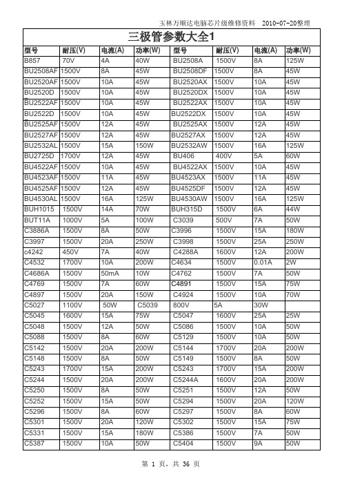
常用三极管参数大全
玉林万顺达电脑芯片级维修资料 2010-07-20整理玉林万顺达电脑芯片级维修资料 2010-07-20整理玉林万顺达电脑芯片级维修资料 2010-07-20整理玉林万顺达电脑芯片级维修资料 2010-07-20整理玉林万顺达电脑芯片级维修资料 2010-07-20整理玉林万顺达电脑芯片级维修资料 2010-07-20整理玉林万顺达电脑芯片级维修资料 2010-07-20整理玉林万顺达电脑芯片级维修资料 2010-07-20整理玉林万顺达电脑芯片级维修资料 2010-07-20整理玉林万顺达电脑芯片级维修资料 2010-07-20整理玉林万顺达电脑芯片级维修资料 2010-07-20整理玉林万顺达电脑芯片级维修资料 2010-07-20整理玉林万顺达电脑芯片级维修资料 2010-07-20整理玉林万顺达电脑芯片级维修资料 2010-07-20整理玉林万顺达电脑芯片级维修资料 2010-07-20整理玉林万顺达电脑芯片级维修资料 2010-07-20整理玉林万顺达电脑芯片级维修资料 2010-07-20整理玉林万顺达电脑芯片级维修资料 2010-07-20整理玉林万顺达电脑芯片级维修资料 2010-07-20整理玉林万顺达电脑芯片级维修资料 2010-07-20整理玉林万顺达电脑芯片级维修资料 2010-07-20整理玉林万顺达电脑芯片级维修资料 2010-07-20整理玉林万顺达电脑芯片级维修资料 2010-07-20整理玉林万顺达电脑芯片级维修资料 2010-07-20整理玉林万顺达电脑芯片级维修资料 2010-07-20整理玉林万顺达电脑芯片级维修资料 2010-07-20整理玉林万顺达电脑芯片级维修资料 2010-07-20整理玉林万顺达电脑芯片级维修资料 2010-07-20整理玉林万顺达电脑芯片级维修资料 2010-07-20整理玉林万顺达电脑芯片级维修资料 2010-07-20整理。
测功机使用说明书(中文)
CW系列电涡流测功机主机使用说明书凯迈(洛阳)机电有限公司(原洛阳南峰机电设备制造有限公司)目录1、引言 (4)1.1概述 (4)1.2电涡流测功机型号含义及技术参数 (4)2、涡流制动器的工作原理和主机结构 (6)2.1涡流制动器的工作原理 (6)2.2功率计算 (6)2.3主机结构 (6)2.4报警装置 (7)3、电涡流测功机主要技术指标 (7)4、涡流测功机的布置和安装 (8)4.1测功机的工作条件 (8)4.2 测功机的布置 (8)4.3 测功机的安装 .......................................................... .85、测功机的冷却 (11)5.1. ......................................................................................................................... 冷却原理 (11)5.2对冷却水水质的要求 (11)5.3确定冷却水水量 (11)&电涡流测功机的润滑 (12)6.1油润滑 (12)6.2脂润滑 (12)6.3摆动轴承的润滑 (13)7、电涡流测功机校准和调节 (13)7.1 静校 (13)7.2 灵敏度检查 (18)8、电涡流测功机的运输和维护 (18)8.1 测功机的贮存 (18)8.2 测功机的运输 (18)8.3 测功机的检查和维护 (19)9、配套 (20)10、.................................... CW盘式电涡流测功机的常见故障和排除方法2111、.......................................................... 润滑泵的使用和维护2212、图册部分 (24)图1(a)〜(b)电涡流测功机的主机结构 (25)图2(a)〜(o)电涡流测功机的机械特性曲线 (27)图3(a)〜(I)电涡流测功机的外形尺寸 (42)图4(a)〜(i)电涡流测功机的接线图 (54)图5水量、水温差及功率之间的关系 (63)1、引言1.1概述我公司根据德国策尔纳(Z?LLNER公司专有技术生产的CW系列电涡流测功机,具有低惯性、高精度、高稳定性和结构简单、维修方便、自成系列并适用于操作控制自动化等优点。
帕顿530以太网防雷器说明书.pdf
3
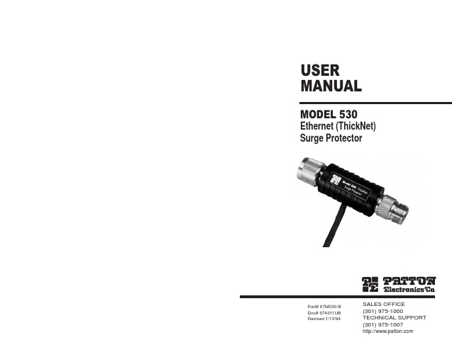
Using a hybrid circuit that incorporates Silicon Avalanche Diodes, the Model 530 can take repeated "hits" up to its rated capacity without degrading in performance. If the Model 530 should encounter a severe transient above its voltage rating, it will fail "open" to protect the connected hardware from damage. In this case, all signals (including data) are sent directly to ground, indicating to you that the Model 530 has "sacrificed itself" for your system and needs to be replaced.
• Operates at data rates to 10 Mbps
• Provides separate connection to chassis ground for surge handling
• Easy to install
DESCRIPTION
The Patton Model 530 thick Ethernet surge protector guards N-type Ethernet ports and connected equipment against data loss and hardware damage due to transient surges. Providing 1.8 Kilowatts of clamping transient protection, the Model 530 is easy to install and won't slow network performance.
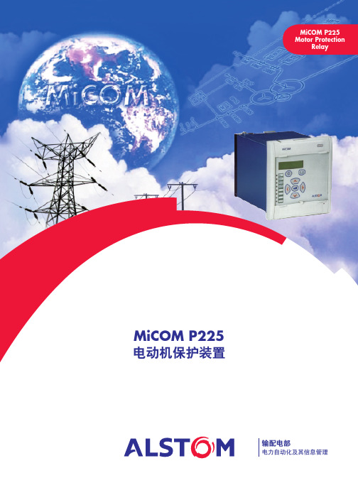
MICOM-P520-电动机保护资料
!"#$%&'"#$()
!(
)
:90%
!"#$%&'
!"#$% !"#$% !"#$ !"#$ % !"
!"#$%& !"# !" !" !" #
!"#$%&'()*+,
!"#$%
!" äÉÖE
!"#$ I
F
1
!"#$
!"#$%&'( !"#$%&' MiCOM P225
!"#$%&'()*+,
2
!"#$
!"# 52 52+ !
!
1 0.1s 1 - 5 Iθ
!" Istart 0.5 Iθ 1s
CT
CT 1 - 3000A CT 1 - 3000A CT 1A 5A CT 1A 5A !"# CT 5P10-5VA !" CT CT !" CT !"#$%&'()*+ ! 1A 1A
! 0 - 100s !" /
!"#$%&'( )
4 MiCOM S10
!
!"#$%&'()*+, !"#$% !"
3 MiCOM S1 !" !"#$%&
!"#$
!"# !"# !
$%&'"() !"# !%&' !"#$% MiCOM
RCWP510010R0ZMWB中文资料
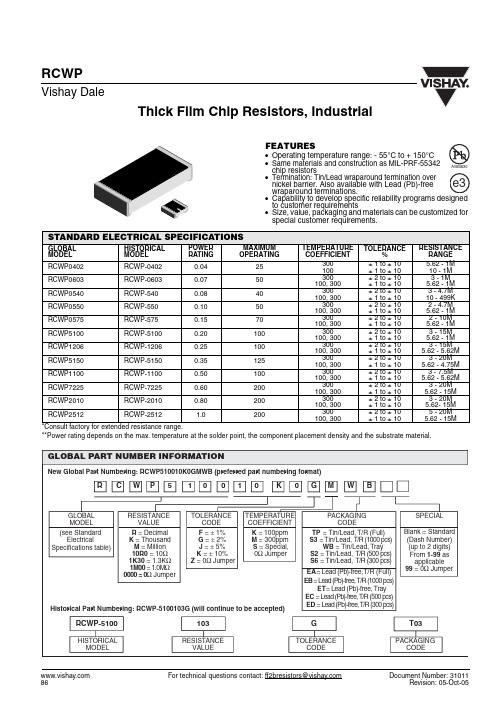
Thick Film Chip Resistors, Industrial For technical questions contact: ff2bresistors@Document Number: 31011RCWPVishay DaleFEATURES•Operating temperature range: - 55°C to + 150°C•Same materials and construction as MIL-PRF-55342chip resistors•Termination: Tin/Lead wraparound termination overnickel barrier. Also available with Lead (Pb)-freewraparound terminations.•to customer requirements•Size, value, packaging and materials can be customized for special customer requirements.*Consult factory for extended resistance range.**Power rating depends on the max. temperature at the solder point, the component placement density and the substrate material.STANDARD ELECTRICAL SPECIFICATIONSGLOBAL MODEL HISTORICAL MODEL POWER RATING MAXIMUM OPERATINGTEMPERATURE COEFFICIENTTOLERANCE%RESISTANCE RANGE RCWP0402RCWP-04020.0425300100± 1 to ± 10± 1 to ± 10 5.62 - 1M 10 - 1M RCWP0603RCWP-06030.0750300100, 300± 2 to ± 10± 1 to ± 10 3 - 1M 5.62 - 1M RCWP0540RCWP-5400.0840300100, 300± 2 to ± 10± 1 to ± 10 3 - 4.7M 10 - 499K RCWP0550RCWP-5500.1050300100, 300± 2 to ± 10± 1 to ± 10 2 - 4.7M 5.62 - 1M RCWP0575RCWP-5750.1570300100, 300± 2 to ± 10± 1 to ± 10 2 - 10M 5.62 - 1M RCWP5100RCWP-51000.20100300100, 300± 2 to ± 10± 1 to ± 10 3 - 15M 5.62 - 1M RCWP1206RCWP-12060.25100300100, 300± 2 to ± 10± 1 to ± 10 3 - 15M 5.62 - 5.62M RCWP5150RCWP-51500.35125300100, 300± 2 to ± 10± 1 to ± 10 3 - 20M 5.62 - 4.75M RCWP1100RCWP-11000.50100300100, 300± 2 to ± 10± 1 to ± 10 3 - 7.5M 5.62 - 5.62M RCWP7225RCWP-72250.60200300100, 300± 2 to ± 10± 1 to ± 10 3 - 20M 5.62 - 15M RCWP2010RCWP-20100.80200300100, 300± 2 to ± 10± 1 to ± 10 3 - 20M 5.62- 15M RCWP2512RCWP-25121.0200300100, 300± 2 to ± 10± 1 to ± 105 - 20M 5.62 - 15MRCWPThick Film Chip Resistors, IndustrialVishay DaleDocument Number: 31011For technical questions contact: ff2bresistors@DIMENSIONSDIMENSIONS [in millimeters]GLOBAL MODEL A (Len g th)B (Width)C (Hei g ht)D(Top Term)E(Bottom Term)RCWP04020.039 ± 0.003[0.99 ± 0.08]0.020 ± 0.003[0.51 ± 0.08]0.013 ± 0.003[0.33 ± 0.08]0.010 ± 0.005[0.25 ± 0.13]0.010 ± 0.005[0.25 ± 0.13]RCWP05400.055 ± 0.005[1.40 ± 0.13]0.040 ± 0.005[1.02 ± 0.13]0.020 ± 0.005[0.51 ± 0.13]0.010 ± 0.005[0.25 ± 0.13]0.010 ± 0.005[0.25 ± 0.13]RCWP05500.055 ± 0.005[1.40 ± 0.13]0.050 ± 0.005[1.27 ± 0.13]0.020 ± 0.005[0.51 ± 0.13]0.010 ± 0.005[0.25 ± 0.13]0.015 ± 0.005[0.38 ± 0.13]RCWP05750.080 ± 0.005[2.03 ± 0.13]0.050 ± 0.005[1.27 ± 0.13]0.020 ± 0.005[0.51 ± 0.13]0.015 ± 0.005[0.38 ± 0.13]0.015 ± 0.005[0.38 ± 0.13]RCWP06030.063 ± 0.005[1.60 ± 0.13]0.032 ± 0.005[0.81 ± 0.13]0.018 ± 0.005[0.46 ± 0.13]0.012 ± 0.005[0.31 ± 0.13]0.015 ± 0.005[0.38 ± 0.13]RCWP11000.105 ± 0.005[2.67 ± 0.13]0.100 ± 0.005[2.54 ± 0.13]0.020 ± 0.005[0.51 ± 0.13]0.015 ± 0.005[0.38 ± 0.13]0.015 ± 0.005[0.38 ± 0.13]RCWP12060.125 ± 0.005[3.18 ± 0.13]0.063 ± 0.005[1.60 ± 0.13]0.020 ± 0.005[0.51 ± 0.13]0.015 ± 0.005[0.38 ± 0.13]0.015 ± 0.005[0.38 ± 0.13]RCWP20100.197 ± 0.006[5.00 ± 0.15]0.098 ± 0.005[2.49 ± 0.13]0.020 ± 0.005[0.51 ± 0.13]0.020 ± 0.005[0.51 ± 0.13]0.020 ± 0.005[0.51 ± 0.13]RCWP25120.250 ± 0.006[6.35 ± 0.15]0.124 ± 0.005[3.15 ± 0.13]0.020 ± 0.005[0.51 ± 0.13]0.020 ± 0.005[0.51 ± 0.13]0.020 ± 0.005[0.51 ± 0.13]RCWP51000.105 ± 0.005[02.67 ± 0.13]0.050 ± 0.005[1.27 ± 0.13]0.020 ± 0.005[0.51 ± 0.13]0.015 ± 0.005[0.38 ± 0.13]0.015 ± 0.005[0.38 ± 0.13]RCWP51500.155 ± 0.005[3.94 ± 0.13]0.050 ± 0.005[1.27 ± 0.13]0.020 ± 0.005[0.51 ± 0.13]0.015 ± 0.005[0.38 ± 0.13]0.015 ± 0.005[0.38 ± 0.13]RCWP72250.230 ± 0.005[5.84 ± 0.13]0.075 ± 0.005[1.91 ± 0.13]0.020 ± 0.005[0.51 ± 0.13]0.020 ± 0.005[0.51 ± 0.13]0.020 ± 0.005[0.51 ± 0.13]Legal Disclaimer NoticeVishayNoticeSpecifications of the products displayed herein are subject to change without notice. Vishay Intertechnology, Inc., or anyone on its behalf, assumes no responsibility or liability for any errors or inaccuracies.Information contained herein is intended to provide a product description only. No license, express or implied, by estoppel or otherwise, to any intellectual property rights is granted by this document. Except as provided in Vishay's terms and conditions of sale for such products, Vishay assumes no liability whatsoever, and disclaims any express or implied warranty, relating to sale and/or use of Vishay products including liability or warranties relating to fitness for a particular purpose, merchantability, or infringement of any patent, copyright, or other intellectual property right. The products shown herein are not designed for use in medical, life-saving, or life-sustaining applications. Customers using or selling these products for use in such applications do so at their own risk and agree to fully indemnify Vishay for any damages resulting from such improper use or sale.。
WT2000系列风力发电机组风场安装手册补充工艺A

(1)按照表 4-2 中的接线要求,将电缆-W1.1 一端的黄、绿、红、蓝、黄绿芯线分别接入变
压器柜(63kVA)出线断路器-QF2 和变压器柜(63kVA)接地母排的相应端子上,并均用 M8 螺
栓组件进行紧固,紧固力矩为 16Nm。
(2)按照表 4-2 中的接线要求,将电缆-W1.1 另一端的黄、绿、红芯线先分别穿入塔基柜
文件号:WT2000-086/093/100-NCV/CCV-2292-010-D-A
第5页
共8页
许昌许继风电科技有限公司
(8)在膨胀螺栓的螺纹部分涂抹适量螺纹锁固胶 Loctite243,然后依次装入平垫圈(倒角向 外)、弹簧垫圈和螺母。
(9)用两用快扳 18 将膨胀螺栓拧紧,然后用预置式扭力扳手 A□60-300Nm 以 60Nm 的力 矩将其紧固。
WT2000 系列风力发电机组 风场安装手册补充工艺 A
编 制: 校 对: 审 核: 会 签: 审 定: 批 准:
年月日
文件号:WT2000-086/093/100-NCV/CCV-2292-010-D-A
第1页
共8页
许昌许继风电科技有限公司
目录 变更 ............................................................................................................................................................................. 3 参考 ............................................................................................................................................................................. 3 1 总则 ......................................................................................................................................................................... 4 2 变压器柜(63kVA)的安装 .................................................................................................................................. 4
RCWP5100RZKS3中文资料
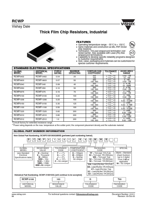
Thick Film Chip Resistors, Industrial For technical questions contact: ff2bresistors@Document Number: 31011RCWPVishay DaleFEATURES•Operating temperature range: - 55°C to + 150°C•Same materials and construction as MIL-PRF-55342chip resistors•Termination: Tin/Lead wraparound termination overnickel barrier. Also available with Lead (Pb)-freewraparound terminations.•to customer requirements•Size, value, packaging and materials can be customized for special customer requirements.*Consult factory for extended resistance range.**Power rating depends on the max. temperature at the solder point, the component placement density and the substrate material.STANDARD ELECTRICAL SPECIFICATIONSGLOBAL MODEL HISTORICAL MODEL POWER RATING MAXIMUM OPERATINGTEMPERATURE COEFFICIENTTOLERANCE%RESISTANCE RANGE RCWP0402RCWP-04020.0425300100± 1 to ± 10± 1 to ± 10 5.62 - 1M 10 - 1M RCWP0603RCWP-06030.0750300100, 300± 2 to ± 10± 1 to ± 10 3 - 1M 5.62 - 1M RCWP0540RCWP-5400.0840300100, 300± 2 to ± 10± 1 to ± 10 3 - 4.7M 10 - 499K RCWP0550RCWP-5500.1050300100, 300± 2 to ± 10± 1 to ± 10 2 - 4.7M 5.62 - 1M RCWP0575RCWP-5750.1570300100, 300± 2 to ± 10± 1 to ± 10 2 - 10M 5.62 - 1M RCWP5100RCWP-51000.20100300100, 300± 2 to ± 10± 1 to ± 10 3 - 15M 5.62 - 1M RCWP1206RCWP-12060.25100300100, 300± 2 to ± 10± 1 to ± 10 3 - 15M 5.62 - 5.62M RCWP5150RCWP-51500.35125300100, 300± 2 to ± 10± 1 to ± 10 3 - 20M 5.62 - 4.75M RCWP1100RCWP-11000.50100300100, 300± 2 to ± 10± 1 to ± 10 3 - 7.5M 5.62 - 5.62M RCWP7225RCWP-72250.60200300100, 300± 2 to ± 10± 1 to ± 10 3 - 20M 5.62 - 15M RCWP2010RCWP-20100.80200300100, 300± 2 to ± 10± 1 to ± 10 3 - 20M 5.62- 15M RCWP2512RCWP-25121.0200300100, 300± 2 to ± 10± 1 to ± 105 - 20M 5.62 - 15MRCWPThick Film Chip Resistors, IndustrialVishay DaleDocument Number: 31011For technical questions contact: ff2bresistors@DIMENSIONSDIMENSIONS [in millimeters]GLOBAL MODEL A (Len g th)B (Width)C (Hei g ht)D(Top Term)E(Bottom Term)RCWP04020.039 ± 0.003[0.99 ± 0.08]0.020 ± 0.003[0.51 ± 0.08]0.013 ± 0.003[0.33 ± 0.08]0.010 ± 0.005[0.25 ± 0.13]0.010 ± 0.005[0.25 ± 0.13]RCWP05400.055 ± 0.005[1.40 ± 0.13]0.040 ± 0.005[1.02 ± 0.13]0.020 ± 0.005[0.51 ± 0.13]0.010 ± 0.005[0.25 ± 0.13]0.010 ± 0.005[0.25 ± 0.13]RCWP05500.055 ± 0.005[1.40 ± 0.13]0.050 ± 0.005[1.27 ± 0.13]0.020 ± 0.005[0.51 ± 0.13]0.010 ± 0.005[0.25 ± 0.13]0.015 ± 0.005[0.38 ± 0.13]RCWP05750.080 ± 0.005[2.03 ± 0.13]0.050 ± 0.005[1.27 ± 0.13]0.020 ± 0.005[0.51 ± 0.13]0.015 ± 0.005[0.38 ± 0.13]0.015 ± 0.005[0.38 ± 0.13]RCWP06030.063 ± 0.005[1.60 ± 0.13]0.032 ± 0.005[0.81 ± 0.13]0.018 ± 0.005[0.46 ± 0.13]0.012 ± 0.005[0.31 ± 0.13]0.015 ± 0.005[0.38 ± 0.13]RCWP11000.105 ± 0.005[2.67 ± 0.13]0.100 ± 0.005[2.54 ± 0.13]0.020 ± 0.005[0.51 ± 0.13]0.015 ± 0.005[0.38 ± 0.13]0.015 ± 0.005[0.38 ± 0.13]RCWP12060.125 ± 0.005[3.18 ± 0.13]0.063 ± 0.005[1.60 ± 0.13]0.020 ± 0.005[0.51 ± 0.13]0.015 ± 0.005[0.38 ± 0.13]0.015 ± 0.005[0.38 ± 0.13]RCWP20100.197 ± 0.006[5.00 ± 0.15]0.098 ± 0.005[2.49 ± 0.13]0.020 ± 0.005[0.51 ± 0.13]0.020 ± 0.005[0.51 ± 0.13]0.020 ± 0.005[0.51 ± 0.13]RCWP25120.250 ± 0.006[6.35 ± 0.15]0.124 ± 0.005[3.15 ± 0.13]0.020 ± 0.005[0.51 ± 0.13]0.020 ± 0.005[0.51 ± 0.13]0.020 ± 0.005[0.51 ± 0.13]RCWP51000.105 ± 0.005[02.67 ± 0.13]0.050 ± 0.005[1.27 ± 0.13]0.020 ± 0.005[0.51 ± 0.13]0.015 ± 0.005[0.38 ± 0.13]0.015 ± 0.005[0.38 ± 0.13]RCWP51500.155 ± 0.005[3.94 ± 0.13]0.050 ± 0.005[1.27 ± 0.13]0.020 ± 0.005[0.51 ± 0.13]0.015 ± 0.005[0.38 ± 0.13]0.015 ± 0.005[0.38 ± 0.13]RCWP72250.230 ± 0.005[5.84 ± 0.13]0.075 ± 0.005[1.91 ± 0.13]0.020 ± 0.005[0.51 ± 0.13]0.020 ± 0.005[0.51 ± 0.13]0.020 ± 0.005[0.51 ± 0.13]Legal Disclaimer NoticeVishayNoticeSpecifications of the products displayed herein are subject to change without notice. Vishay Intertechnology, Inc., or anyone on its behalf, assumes no responsibility or liability for any errors or inaccuracies.Information contained herein is intended to provide a product description only. No license, express or implied, by estoppel or otherwise, to any intellectual property rights is granted by this document. Except as provided in Vishay's terms and conditions of sale for such products, Vishay assumes no liability whatsoever, and disclaims any express or implied warranty, relating to sale and/or use of Vishay products including liability or warranties relating to fitness for a particular purpose, merchantability, or infringement of any patent, copyright, or other intellectual property right. The products shown herein are not designed for use in medical, life-saving, or life-sustaining applications. Customers using or selling these products for use in such applications do so at their own risk and agree to fully indemnify Vishay for any damages resulting from such improper use or sale.。
东元牌热磁式断路器使用说明书
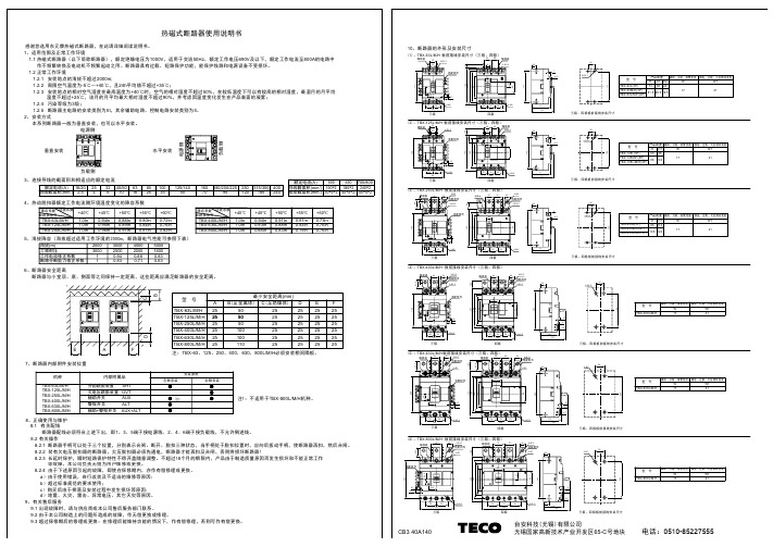
0.82In0.76In +60℃+55℃0.87In0.84In 0.91In0.89In 0.96In0.95In 1.0In+50℃+45℃1.0In TBX-125L/M/H +40℃断路器型号环境系数降容系数4、热动脱扣器额定工作电流随环境温度变化的降容系数热磁式断路器使用说明书感谢您选用东元牌热磁式断路器,在此请详细阅读说明书。
1、适用范围及正常工作环境1.1 热磁式断路器(以下简称断路器),额定绝缘电压为1000V ,适用于交流50Hz ,额定工作电压690V 及以下,额定工作电流至800A 的电路中 作不频繁转换及电动机不频繁起动之用。
断路器具有过载、短路保护功能,能保护线路和电源设备不受损坏。
1.2 正常工作环境1.2.1 安装地点的海拔不超过2000m;1.2.2 周围空气温度为-5℃~+40℃,且24h 平均值不超过+35℃;1.2.3 安装地点的相对空气湿度在最高温度为+40℃时,空气的相对湿度不超过50%,在较低温度下可以有较高的相对湿度,最湿月的月平均 温度不超过+25℃,该月的月平均最大相对湿度不超过90%,并考虑因温度变化发生在产品表面的凝雾; 1.2.4 污染等级为3级;1.2.5 断路器主电路的安装类别为III ,其余辅助电路、控制电路安装类别为II 。
2、安装方式本系列断路器一般为垂直安装,也可以水平安装。
垂直安装电源侧负载侧负载侧电源侧水平安装3、连接导线的截面积和相适应的额定电流2.5导线截面积(mm )16/20额定电流(A)225432640/50106316802510035125/1405016070180/200/225952501206、断路器安全距离7、断路器内部附件安装位置8、正确使用与维护8.1 有关配线断路器配线必须符合上进下出,即1、3、5端子接电源线,2、4、6端子接负载线,不允许倒进线。
8.2 有关操作8.2.1 断路器手柄可以处于三个位置,分别表示合闸、断开、脱扣三种状态,当手柄处于脱扣位置时,应向后扳动手柄,使断路器再扣,然后合闸。
2050培训讲义

电台编程
• • 选择信道 信道编程
编程功能
2050电台有三种编程方式:• 用2050编程软件通过计算机编程,可以通过电台的辅助插口或前面板的红外端口传输信息; • 直接用前面板的键盘编程;
注意:- 这个功能可以由网络管理员在计算机编程时禁用。
• 用克隆电缆通过电台的辅助插口复制信息到另一个电台。
注意:- 如果需要,网络管理员可以在PC编程时禁用保护菜单和通用菜单。
保护菜单
常规设置 (General) 设置手咪上/下行键 (Mic Up/Down Keys)
手咪顶部的按键可以设置两种功能:选择信道和控制音量。也可以设置为禁用。
用翻页键选择需要的功能,然后按
键确认:
:
常规设置 “发送完毕”提示音 (Tx Over Beep)
8.
9.
CW电键输入
扬声器输出
10. 机壳接地
用户控制 - 2050 键盘
呼叫键 信道上行键 通用翻页键
音量增加 通用翻页键
信道下行键 通用翻页键
音量降低 通用翻页键
电源开/关
确认键
紧急呼叫键
向左翻页 数字键 1 向下翻页 ‘jkl ‟ 和 ‘5’ 进入调谐 接收方式 ‘ghi ‟ 和‘4’ 方式选择
天线类型 (Antenna Type)
I/O设置
选择所连接天线的类型,可以 以下5种选择:
Base Station( 基站) 使用宽带天线时选择此项。 910 Mobile antenna(910车载天线) 使用2019或910车载鞭天线时选择此项。 911 Automatic Tuner(911自动天调) 使用911自动天调或其它自动天调时选择此项。 Linear amplifier(线性放大器)
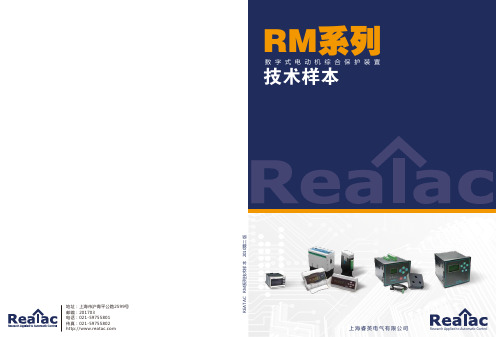
睿英电气RM系列数字式电动机综合保护装置
RM030
RM050
RM100
RM150
RM200
型号
工作电压 频率 三相
功率因数保护
谐波测量保护
温度测量保护
功率保护
欠/过电流保护
保护功能
缺相保护 不平衡保护
逆相保护
堵转保护
短路保护
接地保护
失速保护
通讯MODBUS 4~20mA输出
产品概述,功能与特点·······················································································2 型号选择················································································································3 安装尺寸················································································································5 接线端子,指示灯说明·······················································································6 接线图····················································································································6 技术指标················································································································7
MCW1000中文资料
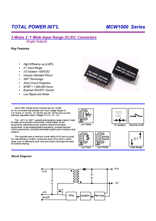
Block DiagramRemote on/offI/O Isolation MCW1000-Series power modules are low-profile dc-dc converters that operate over input voltage ranges of4.5-9VDC, 9-18VDC, 18-36VDC and 36-75VDC and provide precisely regulated output voltages of 3.3V, 5V, 12V.The -40] to +65] operating temperature range makes it ideal for data communication equipments, mobile battery driven equipments, distributed power systems, telecommunicationequipments, mixed analog/digital subsystems, process/machinecontrol equipments, computer peripheral systems and industrial robot systems.The modules have a maximum power rating of 2W and a typical full-load efficiency of 80%, continuous short circuit, 60mV output ripple, built-in filtering for both input and output minimizes the need for external filtering.yLow Ripple and Noisey External ON/OFF-Control y MTBF > 1,000,000 Hours y Short Circuit Protection y SMT Technologyy Industry Standard Pinout y I/O Isolation 1000VDC y 2:1 Input Rangey High Efficiency up to 80%Key FeaturesSingle Outputs2 Watts 2 :1 Wide Input Range DC/DC ConvertersTOTAL POWER INT'L MCW1000 Series79534216712MCW104373571004005MCW1042718491255003.348( 36 ~ 75 )MCW1041 811034216712MCW1033771091004005MCW10327210961255003.324( 18 ~ 36 )MCW1031 802094216712MCW1023772171004005MCW102273201841255003.312( 9 ~ 18 )MCW1021755344216712MCW1013735481004005MCW101270404711255003.35( 4.5 ~ 9 )MCW1011% (Typ.)mA (Typ.)mA (Typ.)mA mA VDC VDC@Max. Load @No Load @Max. Load Min.Max.Efficiency Input CurrentOutput Current Output Voltage Input Voltage Model NumberModel Selection GuideFree-Air ConvectionCooling%95---Humidity ]+105-55Storage Temperature ]+90-40CaseOperating Temperature ]+65-40Ambient Operating Temperature Unit Max.Min.Conditions ParameterEnvironmental SpecificationsExceeding these values can damage the module. These are not continuous operating ratings.mW1,800---Internal Power Dissipation]260---Lead Temperature (1.5mm from case for 10 Sec.)VDC 100-0.748VDC Input ModelsVDC 50-0.724VDC Input ModelsVDC 25-0.712VDC Input Models VDC 15-0.75VDC Input Models Input Surge Voltage( 1000 mS )Unit Max.Min.ParameterNote :1. Specifications typical at Ta=+25], resistive load,nominal input voltage, rated output current unless otherwise noted.2. Transient recovery time is measured to within 1%error band for a step change in output load of 50%to 100%.3. Ripple & Noise measurement bandwidth is 0-20MHz.4. These power converters require a minimum output loading to maintain specified regulation.5. Operation under no-load conditions will not damage these devices; however they may not meet all listed specifications.6. All DC/DC converters should be externally fused at the front end for protection.7. Other input and output voltage may be available,please contact factory.8. Specifications subject to change without notice.Absolute Maximum RatingsMCW1000 SeriesK Hours------1000MIL-HDBK-217F @ 25], Ground BenignMTBFKHz 650300100Switching Frequency pF 12065---100KHz,1VIsolation Capacitance M[------1000500VDC Isolation Resistance VDC ------1100Flash Tested for 1 SecondIsolation Test Voltage VDC ------100060 SecondsIsolation Voltage Unit Max.Typ.Min.Conditions ParameterGeneral SpecificationsContinuousOutput Short Circuit%/]{0.02{0.01---Temperature Coefficient %{5{3---Transient Response Deviation uS 300100---25% Load Step Change Transient Recovery Time %------120Over Power Protection mV rms.15------Ripple & Noise (20MHz)mV P-P 75------Over Line,Load & Temp Ripple & Noise (20MHz)mV P-P 5030---Ripple & Noise (20MHz)%{0.75{0.5---Io=25% to 100%Load Regulation %{0.5{0.3---Vin=Min. to Max.Line Regulation %{2{1---Output Voltage Accuracy Unit Max.Typ.Min.ConditionsParameterOutput SpecificationsCapacitor typeInput FiltermW 1500------Short Circuit Input Power A 1------All ModelsReverse Polarity Input Current 3422---48V Input Models1711---24V Input Models 8.56.5---12V Input Models 43.5---5V Input Models Under Voltage Shortdown36241648V Input Models1812824V Input Models 974.512V Input Models VDC 4.543.55V Input Models Start VoltageUnitMax.Typ.Min.Model ParameterInput SpecificationsReferenced to Negative InputControl CommonmA1------Control Input Current ( off )mA -0.4------Control Input Current ( on )mA 0.20.1---Device Standby Input Current VDC 15---2.7Supply Offunder 1VDC or open circuitSupply On Unit Max.Typ.Min.ConditionsParameterRemote On/Off ControlMCW1000 SeriesNote: # For each output .uF17017010002200Maximum Capacitive Load Unit 12V 5V 3.3V Models by VoutCapacitive Load135mA Slow - Blow Type350mA Slow - Blow Type700mA Slow - Blow Type1500mA Slow - Blow Type48V Input Models 24V Input Models 12V Input Models 5V Input ModelsInput Fuse Selection GuideInput Voltage Transient RatingMCW1000 SeriesDerating Curve]Ambient TemperatureO u t p u t P o w e r (%)020406080100-405060801001109070MCW1000 SeriesTest ConfigurationsInput Reflected-Ripple Current Test SetupLin (4.7uH) and Cin (220uF, ESR < 1.0[ at 100 KHz) to simulate source impedance.Capacitor Cin, offsets possible battery impedance.Current ripple is measured at the input terminals of the module, measurement bandwidth is 0-500 KHz.Peak-to-Peak Output Noise Measurement Test Use a Cout 0.47uF ceramic capacitor.Scope measurement should be made by using a BNC socket, measurement bandwidth is 0-20 MHz. Position the load between 50 mm and 75 mm from the DC/DC Converter.Design & Feature ConsiderationsMaximum Capacitive LoadThe MCW1000 series has limitation of maximum connected capacitance at the output.The power module may be operated in current limiting mode during start-up, affecting the ramp-up and the startup time.The maximum capacitance can be found in the data.Overcurrent ProtectionTo provide protection in a fault (output overload) condition, the unit is equipped with internal current limiting circuitry and can endure current limiting for an unlimited duration. At the point of current-limit inception, the unit shifts from voltage control to current control. The unit operates normally once the output current is brought back into its specified range.Input Source ImpedanceThe power module should be connected to a lowac-impedance input source. Highly inductive source impedances can affect the stability of the power module.In applications where power is supplied over long lines and output loading is high, it may be necessary to use a capacitor at the input to ensure startup.Capacitor mounted close to the power module helps ensure stability of the unit, it is recommended to use a good quality low Equivalent Series Resistance (ESR < 1.0[ at 100 KHz) capacitor of a 8.2uF for the 5V input devices, a 3.3uF for the 12V input devices and a 1.5uF for the 24V and 48V devices.A good quality low ESR capacitor placed as close as practicable across the load will give the best ripple and noise performance.To reduce output ripple, it is recommended to use 3.3uF capacitors at the output.MCW1000 SeriesMCW1000 SeriesThermal ConsiderationsMany conditions affect the thermal performance of the power module, such as orientation, airflow over the module and board spacing. To avoid exceeding the maximum temperature rating of the components inside the power module, the case temperature must be kept below 90°C.The derating curves are determined from measurements obtained in an experimental apparatus.Units are encapsulated in a low thermal resistance molding compound which has excellent chemical resistance and electrical properties in high humidity environment and over a wide operating temperature range.The encapsulant and outer shell of the unit have UL94V-0 ratings. The leads are tin plated for better soldering.NC: No ConnectionUL94V-0:FlammabilityNo function8-Vout 7 4.8g :Weight +Vout 6No function 5Non-Conductive Black Plastic :Case Material Remote ON/OFF 3+Vin(VCC)20.86*0.37*0.44inches -Vin(GND)121.8*9.3*11.1mm :Case Size Single Output Pin Physical CharacteristicsPin Connections{0.002{0.05Pin .XXX{0.01.XX{0.25.XX{0.01.X{0.25Inches Millimeters Tolerance Single OutputConnecting Pin PatternsTop View ( 2.54 mm / 0.1 inch grids )Mechanical DataMCW1000 Series。
CW1040-3G 产品说明书
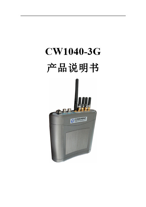
CW1040-3G 产品说明书1 产品介绍该产品是针对背负便携式应用开发的一款产品;可以应用于消防、武警、保险、应急等移动场合;产品自带军用防水包,工作人员可以方便背负在身上。
设备具备多种制式的3G 资源,无线局域网的通讯,GPS 定位,SD 卡存储等功能,确保在绝大多数场合,均能及时上传现场视频及语音信息,或者录制需要信息。
多卡捆绑,带宽明显增大,可及时传输高清流畅音视频到监控中心此设备采用ABS 塑料材质,密封防水;正面为铝板,和塑料塑封在一起,用于主板和模块的散热;整机分为为上下两部分,上面为锂电池及接口,下面为主机板卡,锂电池固定在主机的内部1.1 前后面板图前后面板图1.2 接口定义接口定义前面板前面板 明细明细 状态说明状态说明指示灯 1.2.3.4.为模块指示灯。
文字注明模块类型;EV 表示WVDO 模块,WO 表示WCDA 模熄灭:无卡、模块没工作,或者故障 闪烁:拨号中 常亮:拨号成功块,TD 表示TDSCDMA WIFI 指示灯 熄灭:未使用或者未连接 常亮:联网成功 电源指示灯PWR常亮:电量充足 闪烁:电量不足 熄灭:未开机 SD 卡指示灯常亮:存储中… 熄灭:停止存储天线天线1.2.3.4. 和模块卡槽1.2.3.4.对应 和指示灯1.2.3.4.位置对应WIFI 天线内置WIFI 模块,对应WIFI 指示灯 按钮SD 使能 切换SD 卡存储状态,按下则开始录像,再按则停止(切换不可太频繁)WIFI 使能 切换3G 和WIFI 无线网络使用状态(切换不可太频繁)电源开关电源开关,按下约3秒则开机,再按则关机。
设备起来后灯全亮,加载驱动后全部熄灭,之后再亮1秒后全部熄灭,表示设备起来了 视频 Vedio In 视频输入,BNC,接摄像机音频 Audio In 音频输入,BNC,接麦克风充电Chg外接充电器,初次充电10小时以上 后面板后面板 明细明细 状态说明状态说明网络 RJ45插网线,用于配置设备。
艾顿保护设备组合RCD MCB设备PKP42,2杆说明书
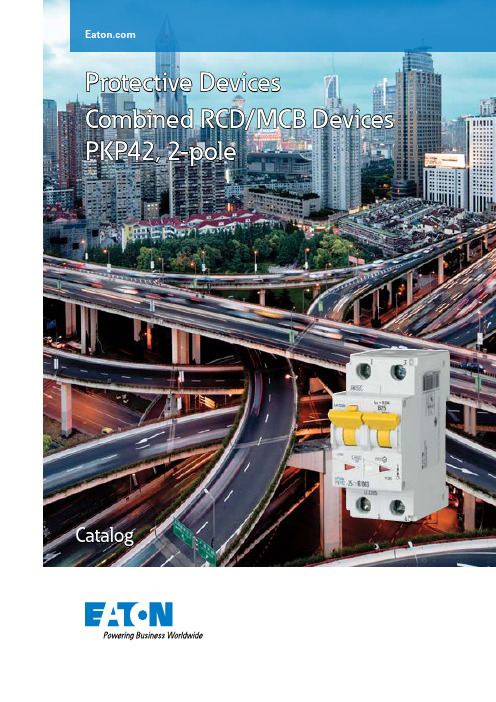
Protective Devices Combined RCD/MCB Devices PKP42, 2-poleCatalog1.1Protective DevicesCombined RCD/MCB Devices PKP42, 2-pole• H igh-quality residual current device / minia-ture circuit breaker combination, line voltage-independent• Contact position indicator red - green • Fault current tripping indicator white - blue • Guide for secure terminal connection • 3-position DIN rail clip, permits removal from existing busbar system• C omprehensive range of accessories can be mounted subsequently• Wide variety of rated tripping currents • Rated currents up to 40 A • Tripping characteristics B, C • Rated breaking capacity 4.5 kADescriptionSG695111.2Protective DevicesCombined RCD/MCB Devices PKP42, 2-poleI n /I D n (A)TypeDesignationArticle No.Units per packageType AC4.5 kA, 2-poleConditionally surge current-proof 250 A, type ACSG6951110/0.03PKP42-10/2/B/0031115811/6013/0.03PKP42-13/2/B/0031115821/6016/0.03PKP42-16/2/B/0031115831/6020/0.03PKP42-20/2/B/0031115841/6025/0.03PKP42-25/2/B/0031115851/6032/0.03PKP42-32/2/B/0031115861/6040/0.03PKP42-40/2/B/0031115871/60Characteristic B SG695116/0.03PKP42-6/2/C/0031116061/6010/0.03PKP42-10/2/C/0031116071/6013/0.03PKP42-13/2/C/0031116081/6016/0.03PKP42-16/2/C/0031116091/6020/0.03PKP42-20/2/C/0031116101/6025/0.03PKP42-25/2/C/0031116111/6032/0.03PKP42-32/2/C/0031116121/6040/0.03PKP42-40/2/C/0031116131/60Characteristic C1.3Protective DevicesCombined RCD/MCB Devices PKP.2, 2-pole - Technical DataSpecifications | Combined RCD/MCB Devices PKP.2, 2-poleDescription• Combined RCD/MCB Devices• Line voltage-independent tripping• Compatible with standard busbar• T win-purpose terminal (lift/open-mouthed) above and below• B usbar positioning optionally above or below• F ree terminal space despite installed busbar• Guide for secure terminal connection• Switching toggle (MCB component) in colour designating the rated current • Contact position indicator red - green• Fault current tripping indicator white - blue• Comprehensive range of accessories can be mounted subsequently• T he test key “T” must be pressed every 6 month. The system operator must be informed of this obligation and his responsibility in a way that can be proven (self-adhesive RCD-label enclosed). The test intervall of 6 month is valid for residential and similar applications. Under all other conditions (e.g. damply or dusty environments), it’s recommended to test in shorter intervalls (e.g. monthly).• P ressing the test key “T” serves the only purpose of function testing the residual current device (RCD). This test does not make earthing resistance measurement (R E), or proper checking of the earth conductor condition redundant, which must be performed separately.• T ype -A: Protects against special forms of residual pulsating DC which have not been smoothed.• T ype -F: Sensitive to pulsating DC residual current and detection of multi-frequency residual currents up to 1 kHz-Increased protection due to the detection of mixed frequencies-Higher load rating with DC residual currents up to 10 mA-Reduction of nuisance tripping thanks to time delayed tripping and increased current withstand capability of 3 kARecommended for washing machines, dish washers, or motor applications with single-phase drives.• T ype -G/A: High reliability against unwanted tripping. Suitable for any circuit where personal injury or damage to property may occur in case of unwanted tripping. Additionally protects against special forms of residual pulsating DC which have not been smoothed.• O L types: Specifically designed to fulfill the tripping characteristic requirements of I2 £ Iz in the Norwegian electrotechnical standard NEK 400-8-823. 10:28.Accessories:Tripping signal switch for subsequent installation ZP-IHK286052 Shunt trip release ZP-ASA/..248438, 2484391.4Protective DevicesCombined RCD/MCB Devices PKP.2, 2-pole - T echnical DataTechnical DataPKP.2, 2-poleElectricalDesign according toCurrent test marks as printed onto the deviceIEC/EN 61009Line voltage-independent tripping instantaneous surge current proof 250 A (8/20 μs)surge current proof 3 kA (F, -G/A, -G/A-OL) (8/20 μs) Rated voltage U e230 V AC; 50 HzOperational voltage range196-253 VRated tripping current ID n 30, 100, 300 mARated non-tripping current ID no 0.5 ID nSensitivity AC and pulsating DC, Type FSelectivity class3Rated breaking capacity I cnPKPM210 kAPKP62 6 kAPKP42 4.5 kARated current 6 - 40 ARated impulse withstand voltage U imp 4 kV (1.2/50 μs)Characteristic B, CMaximum back-up fuse (short-circuit)100 A gL (>10 kA)Enduranceelectrical components³ 4,000 switching operationsmechanical components³ 20,000 switching operationsMechanicalFrame size45 mmDevice height80 mmDevice width35 mm (2 MU)Mounting 3-position DIN rail clip, permits removal from existing busbar system Degree of protection, switch IP20Degree of protection, built-in IP40Upper and lower terminals open-mouthed/lift terminalsTerminal protection finger and hand touch safe, DGUV VS3, EN 50274Terminal capacity 1 - 25 mm2Terminal torque 2 - 2.4 NmBusbar thickness 0.8 - 2 mmOperating temperature -25°C to +40°CStorage- and transport temperature-35°C to +60°CResistance to climatic conditions according to IEC/EN 61009Connection diagramDimensions (mm)1.5Protective DevicesCombined RCD/MCB Devices PKP.2, 2-pole - Technical DataPKPM2: Influence of ambient temperature on load carrying capacity• Values = max. allowed current in Ampere at the specific temperature • Temperature factor (%/K) = 0.5PKP62, PKP42: Influence of ambient temperature on load carrying capacity• Values = max. allowed current in Ampere at the specific temperature • Temperature factor (%/K) = 0.5Tripping Characteristic PKP.2, Characteristics B and CAmbient temperature / °CAmbient temperature / °C1.6Protective DevicesCombined RCD/MCB Devices PKP.2, 2-pole - Technical DataPKPM2Neozed 1)I n [A]162025323540506380100B10<0.50.50.92 2.3 3.78101010<0.50.50.8 1.7 1.936101010Short-circuit Selectivity PKPM2 towards Neozed 1) / Diazed 2) / NH003)Short-circuit currents in kA, rated currents of fuses in A Short-circuit selectivity PKPM2 towards Neozed 1)1) S IEMENS Type 5SE2; Size: D01, D02, D03; Operating class gG; Rated voltage: AC 400 V/DC 250 V2) S IEMENS Type 5SB2, 5SB4, 5SC2; Size: DII, DIII, DIV; Operating class gG; Rated voltage: AC 500 V/DC 500 V 3) S IEMENS Type 3NA3 8, 3NA6 8, 3NA7 8; Size: 000, 00; Operating class gG; Rated voltage: AC 500 V/DC 250 VShort-circuit selectivity PKPM2 towards Diazed 2)Darker areas: no selectivityShort-circuit selectivity PKPM2 towards NH003)PKPM2Diazed 2)I n [A]1620253235506380100B10<0.50.50.9 1.8 2.9 5.6101010<0.50.50.8 1.5 2.4 4.5101010PKPM2NH00 3)I n [A]162025323540506380100125160B10<0.5<0.50.8 1.5 2.3 3.2 5.79.110101010<0.5<0.50.8 1.3 1.9 2.7 4.4 6.5101010101.7Protective DevicesCombined RCD/MCB Devices PKP.2, 2-pole - Technical DataShort-circuit Selectivity PKP62 towards Neozed 1) / Diazed 2) / NH003)Short-circuit currents in kA, rated currents of fuses in A Short-circuit selectivity PKP62 towards Neozed 1)Short-circuit selectivity PKP62 towards Diazed 1)1) S IEMENS Type 5SE2; Size: D01, D02, D03; Operating class gG; Rated voltage: AC 400 V/DC 250 V2) S IEMENS Type 5SB2, 5SB4, 5SC2; Size: DII, DIII, DIV; Operating class gG; Rated voltage: AC 500 V/DC 500 V 3) S IEMENS Type 3NA3 8, 3NA6 8, 3NA7 8; Size: 000, 00; Operating class gG; Rated voltage: AC 500 V/DC 250 VDarker areas: no selectivityShort-circuit selectivity PKP62 towards NH003)PKP62Neozed 1)I n [A]162025323540506380100B10<0.50.50.92 2.3 3.76666<0.50.50.8 1.7 1.936666PKP62Diazed 2)I n [A]1620253235506380100B10<0.50.50.9 1.8 2.9 5.6666<0.50.50.8 1.5 2.4 4.5666PKP62NH00 3)I n [A]162025323540506380100125160B10<0.5<0.50.8 1.5 2.3 3.2 5.7666661.8Protective DevicesCombined RCD/MCB Devices PKP.2, 2-pole - T echnical DataShort-circuit Selectivity PKP42 towards Neozed 1) / Diazed 2) / NH003)Short-circuit currents in kA, rated currents of fuses in A Short-circuit selectivity PKP42 towards Neozed 1)Short-circuit selectivity PKP42 towards Diazed 1)1) S IEMENS Type 5SE2; Size: D01, D02, D03; Operating class gG; Rated voltage: AC 400 V/DC 250 V2) S IEMENS Type 5SB2, 5SB4, 5SC2; Size: DII, DIII, DIV; Operating class gG; Rated voltage: AC 500 V/DC 500 V 3) S IEMENS Type 3NA3 8, 3NA6 8, 3NA7 8; Size: 000, 00; Operating class gG; Rated voltage: AC 500 V/DC 250 VDarker areas: no selectivityShort-circuit selectivity PKP42 towards NH003)PKP42Neozed 1)I n [A]162025323540506380100B10<0.50.50.92 2.3 3.7 4.5 4.5 4.5 4.5<0.50.50.8 1.7 1.93 4.5 4.5 4.5 4.5PKP42Diazed 2)I n [A]1620253235506380100B10<0.50.50.9 1.8 2.9 4.5 4.5 4.5 4.5<0.50.50.8 1.5 2.4 4.5 4.5 4.5 4.5PKP42NH00 3)I n [A]162025323540506380100125160B10<0.5<0.50.8 1.5 2.3 3.2 4.5 4.5 4.5 4.5 4.5 4.51.9Protective DevicesCombined RCD/MCB Devices PKP.2, 2-pole - Technical DataLet-through Energy PKP.2-../2/Let-through Energy PKPM2, Characteristic B, 2-poleLet-through Energy PKPM2, Characteristic C, 2-poleProspective Short-circuit Current I cc [A]L e t -t h r o u g h E n e r g y I 2t [A 2 s e c]L e t -t h r o u g h E n e r g y I 2t [A 2 s e c ]Prospective Short-circuit Current I cc [A]Let-through Energy PKP62, Characteristic B, 2-poleLet-through Energy PKP62, Characteristic C, 2-poleProspective Short-circuit Current I cc [A]L e t -t h r o u g h E n e r g y I 2t [A 2 s e c]L e t -t h r o u g h E n e r g y I 2t [A 2 s e c ]Prospective Short-circuit Current I cc [A]1.1010EATON CORPORATION CA019055ENProtective DevicesCombined RCD/MCB Devices PKP.2, 2-pole - T echnical DataLet-through Energy PKP42, Characteristic B, 2-poleLet-through Energy PKP42, Characteristic C, 2-poleProspective Short-circuit Current I cc [A]L e t -t h r o u g h E n e r g y I 2t [A 2 s e c]L e t -t h r o u g h E n e r g y I 2t [A 2 s e c ]Prospective Short-circuit Current I cc [A]EatonEMEA Headquarters Route de la Longeraie 71110 Morges, Switzerland Eaton.eu© 2020 EatonAll Rights Reserved Printed in AustriaPublication No. CA019055EN Article number 302756-MK December 2020Grafics: SRA, Schrems9010238178311Eaton Industries (Austria) GmbH Scheydgasse 421210 Vienna AustriaFollow us on social media to get the latest product and support information.Eaton is a registered trademark.All other trademarks are property of their respective owners.To contact us please visit https:///us/en-us/support/international-support-contacts.htmlFor technical questions please contact your local Eaton team.Changes to the products, to the information contained in thisdocument, and to prices are reserved; as are errors and omissions.Only order confirmations and technical documentation by Eaton is binding. Photos and pictures also do not warrant a specific layout or functionality. Their use in whatever form is subject to prior approval by Eaton. The same applies to trademarks (especially Eaton, Moeller,and Cutler-Hammer). The Terms and Conditions of Eaton apply, as referenced on Eaton Internet pages and Eaton order confirmations.Eaton’s electrical business is a global leader with deep regionalapplication expertise in power distribution and circuit protection; power quality, backup power and energy storage; control and automation; life safety and security; structural solutions; and harsh and hazardous environment solutions. Through end-to-end services, channel and an integrated digital platform & insights Eaton is powering what matters across industries and around the world, helping customers solve their most critical electrical power management challenges.For more information, visit .。
MGP W M 25 电机说明书
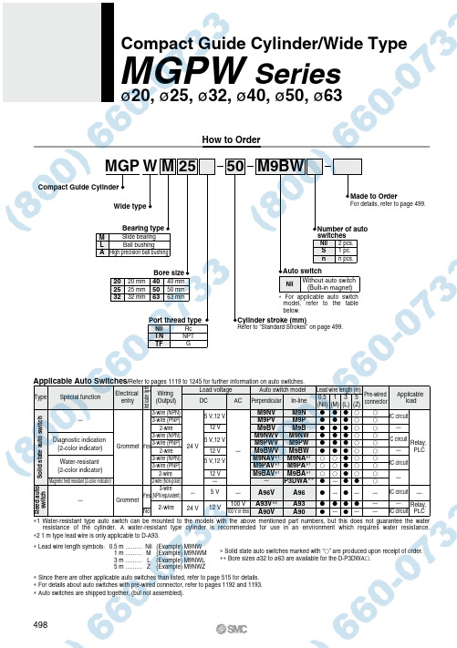
1.0 MPa
Minimum operating pressure
0.1 MPa
Ambient and fluid temperature
−10 to 60°C (No freezing)
Piston speed Note)
50 to 500 mm/s
Cushion
Rubber bumper on both ends
Lubrication Stroke length tolerance
Not required (Non-lube)
+1.5 0
mm
Note) Speed with no load
Standard Strokes
Bore size (mm) 20 to 63
Standard stroke (mm) 25, 50, 75, 100, 125, 150, 175, 200
—
Reed auto switch
—
3-wire Grommet Yes (NPN equivalent)
No 2-wire
— 24 V
5V
—
A96V
12 V
100 V 100 V or less
A93V∗2 A90V
A96
A93 A90
——
——
— IC circuit —
—
— Relay,
Applicable load
Solid state auto switch
—
3-wire (NPN) 3-wire (PNP)
5 V,12 V
M9NV M9PV
M9N M9P
IC circuit
2-wire
12 V
杜邦最大发电器5800Ontario Mills Pkwy产品说明书

Warranty5800 Ontario Mills PkwyOntario, CA 91764 USACall our Customer Care Team Toll Free 8-5 pm PST Mon-Fri844-DUROMAX2WARRANTY5-Year WarrantyAll DuroMax Power Equipment warrant the original purchasers to a 5-Year Parts Warranty (Residential Use ONLY: Unusually heavy or commercial use is covered for a period of 1 year) inthe event of failure due to defects in electrical or mechanical components. Freight on any items submitted for replacement or repair under the warranty is the responsibility of the equipment owner. This warranty is non-transferable and only valid to the original purchaser.Warranty ExclusionsThe DuroMax Power Equipment warranty does not cover repairs or returns when the fault is: Normal wear and tear, installation use or maintenance services, cosmetic defects, accessories, failures due to acts of god or natural disasters, or problems related to/from aftermarket or non-OEM parts.Warranty LimitationsDuroMax Power Equipment does not claim or hold any obligation to loss of time, freight charges, use of the product, or any incidental damages from the use of this product. THIS WARRANTY IS IN LIEU OF ALL OTHER WARRANTIES, EXPRESSED OR IMPLIED.U.S EPA AND CALIFORNIA EMISSION CONTROL WARRANTY STATEMENTYOUR WARRANTY RIGHTS AND OBLIGATIONSThe California Air Resources Board, The United States Environmental Protection Agency (US EPA) and DuroMax Power Equipment are pleased to explain the emission control system warranty on your 2022-2023 year small off-road engine. In the United States and California, new small off-road engines must be designed built and equipped to meet the State’s stringent anti-smog standards. DuroMax Power Equipment must warrant the emission control system on your small off-road engine for the periods of time listed below, provided there has been no abuse neglect or improper maintenance of your small off-road engine.Your emission control system may include parts such as the carburetor or fuel injection system, the ignition system, and a catalytic converter. Also included may be hoses, belts, connectors, and other emission-related assemblies.Where a warrantable condition exists, DuroMax Power Equipment will repair your small off-road engine at no cost to you including diagnosis, parts, and labor.MANUFACTURER’S WARRANTY COVERAGE:As the small off-road engine owner, you are responsible for the performance of the required3maintenance listed in your owner’s manual. DuroMax Power Equipment recommends that you retain all receipts covering maintenance on your small off-road engine, but DuroMax Power Equipment cannot deny warranty solely for the lack of receipts or for your failure to ensure the performance of all scheduled maintenance.As the small off-road engine owner, you should, however, be aware that DuroMax Power Equipment may deny you warranty coverage if your small off-road engine or a part has failed due to abuse, neglect, improper maintenance or unapproved modifications.You are responsible for presenting your small off-road engine to a DuroMax Power Equipment distribution center as soon as a problem exists. The warranty repairs should be completed in a reasonable amount of time, not to exceed 30 days.If you have any questions regarding your warranty rights and responsibilities, contact DuroMax Power Equipment:TEL: 1-844-387-6629WEBSITE: ADDRESS: 5800 Ontario Mills Pkwy, Ontario CA 91764This telephone number is only for the engines which the company name “DuroMax Power Equipment” on the emission label.DEFECTS WARRANTY REQUIREMENTS:(a)The warranty period begins on the date the engine or equipment is delivered to an ultimate purchaser.(b)General Emissions Warranty Coverage. DuroMax Power Equipment warrants to the ultimate purchaser and each subsequent owner that the engine or equipment is:(1)Designed, built, and equipped so as to conform with all applicable regulations adopted byUS EPA & Air Resources Board; and(2)Free from defects in materials and workmanship that causes the failure of a warrantedpart for a period of two years.(c)The warranty on emissions-related parts will be interpreted as below:(1)Any warranted part that is not scheduled for replacement as required maintenance inthe written instructions required by subsection (d) must be warranted for the warrantyperiod defined in Subsection(b)(2). If any such part fails during the period of warrantycoverage, it must be repaired or replaced by DuroMax Power Equipment according to4WARRANTY (CONTINUED)Subsection (4) below. Any such part repaired or replaced under the warranty must bewarranted for the remaining warranty period.(2)Any warranted part that is scheduled only for regular inspection in the written instructionsrequired by subsection (d) must be warranted for the warranty period defined in Subsection (b)(2). A statement in such written instructions to the effect of “repair or replace as necessary” willnot reduce the period of warranty coverage. Any such part repaired or replaced under warranty must be warranted for the remaining warranty period.(3)Any warranted part that is scheduled for replacement as required maintenance in the writteninstructions required by Subsection (d) must be warranted for the period of time prior to the first scheduled replacement point for that part. If the part fails prior to the first scheduledreplacement, the part must be repaired or replaced by DuroMax Power Equipment according to Subsection (4) below. Any such part repaired or replaced under warranty must be warranted for the remainder of the period prior to the first scheduled replacement point for the part.(4)Repair or replacement of any warranted part under the warranty must be performed at nocharge to the owner at a warranty station. (5) Notwithstanding the provisions of Subsection(4)above, warranty services or repairs must be provided at all DuroMax Power Equipmentdistribution centers that are franchised to service the subject engines.(6)The owner must not be charged for diagnostic labor that leads to the determination thata warranted part is, in fact, defective provided that such diagnostic work is performed ata warranty station. (7) DuroMax Power Equipment is liable for damages to other enginecomponents proximately caused by a failure under warranty of any warranted part.(8)Throughout the emissions warranty period defined in Subsection (b)(2), DuroMax PowerEquipment must maintain a supply of warranted parts sufficient to meet the expected demand for such parts.(9)Any replacement part may be used in the performance of any warranty maintenance or repairsand must be provided without charge to the owner such use will not reduce the warrantyobligations of DuroMax Power Equipment(10)Add-on or modified parts that are not exempted by the Air Resources Board may not beused. The use of any non-exempted add-on or modified parts will be grounds for disallowing a warranty claim. DuroMax Power Equipment will not be liable to warrant failures of warranted parts caused by the use of a non-exempted add-on or modified part.(11)DuroMax Power Equipment issuing the warranty shall provide any documents that describethat manufacturer’s warranty procedures or policies within five working days of a request by the US EPA & Air Resources Board.5Exhaust Emission Warranty Parts List.(1)Fuel Metering System(i)Carburetor and internal parts (and/orpressure regulator or fuel injectionsystem).(ii)Air/fuel ratio feedback and controlsystem.(iii)Cold start enrichment system.(iv)Fuel tank.(2)Air induction system(i)Controlled hot air intake system.(ii)Intake manifolds.(iii)Air filter.(3)Ignition System(i)Spark Plugs.(ii)Magneto or electronic ignition system.(iii)Spark advance/retard system.(4)Exhaust Gas Recirculation (EGR) System(i)EGR valve body, and carburetor spacerif applicable.(ii)EGR rate feedback and control system.(5)Air Injection System(i)An air pump or pulse valve.(ii)Valves affecting the distribution offlow.(iii)Distribution manifold.(6)Catalyst or Thermal Reactor System(i)Catalytic converter.(ii)Thermal reactor.(iii)Exhaust manifold.(7)Particulate Controls (i)Traps, filters, precipitators, and any other device used to capture particulate emissions.(8)Miscellaneous Items Used in Above Systems (i)Electronic controls (ii)Vacuum, temperature, and time- sensitive valves and switches.(iii)Hoses, belts, connectors, and assemblies.6DuroMax Power Equipment will furnish with each new engine written instructions for the maintenance and use of the engine by the ownerCUSTOMER SERVICEDuroMax Power Equipment is committed to ensuring that our products perform when they need to. Our generators are your lifeline in the event of an emergency. Should you have any problems, please contact our customer service department:DUROMAX POWER EQUIPMENT5800 Ontario Mills ParkwayOntario, CA 91764Customer Service: 844-DUROMAXCustomer Service Hours: 8-5 pm PSTWebsite: Email:********************************75800 Ontario Mills Parkway Ontario, CA 91764United States844-DUROMAX。
兰州电机样本_bbb

)输出电压波形好,从空载到满载,相电压和线电压波形总谐波含量不大于,偏离系数不大于4%;)电压调制不大于1%;不对称负载时三相电压不平衡不大于2%,25%不对称负载时三相电压不平衡不大于)不对称负载时三相电压过零点相位差在120±2︒范围内;)稳态电压调整率不超过±1%;)突变额定功率负载时的瞬态电压调整率不超过±15%或)两套中频同时工作,励磁系统互不干扰。
TFZPW—□4 双频无刷同步发电机双频无刷同步发电机由同轴共外壳的工频无刷同步发电机、成,具有双频发电功能。
当发电机由内燃机驱动运行时,可同时输出互相独立的电功率。
4.1主要特点及性能指标4.1.1 工频无刷同步发电机舰用中频直流电动发电机组潜艇特种辅机,由同轴共外壳的幅压直流电动机和单相中频发电机及控制装置组成。
输入直440V(变化范围350V~640V),输出400Hz、230V单相电功率。
主要特点)满足GJB13-84和GJB69-85;)机—电一体化结构;)频率偏差不超过±3%,稳态电压调整率不超过±2%;)从空载到满载,输出电压波形总谐波含量不大于3%,单个谐波含量不大于双频变频无刷发电机双频变频发电机由同轴共外壳的工频无刷同步电机、中频无刷同步发电机和交流励磁机组成,有双频和变频发电功能。
当由内燃机驱动时作双频发电运行,同时输出互相独立的50Hz种电功率;在有市电时作变频发电运行,此时工频无刷同步电机做电动机运行,输入50Hz中频发电机输出400Hz电功率。
主要特点全无刷结构,对外电磁辐射小;工频和中频励磁系统互不干扰;全封闭轴承。
TFSBPW—□注:□表示双频变频发电机工频与中频额定功率之和。
安装型式和防护等级发电机的安装型式由合同规定,一般为IM B35或IM B25。
发电机的防护等级由合同规定,一般为IP21或IP23。
冷却方式发电机的冷却方式为IC01。
使用环境)海拔高度不超过4000m;外形安装尺寸见表1912.8 外形安装尺寸见表28、表。
KWFB无密封自控自吸泵服务
故障现象
可能产生的原因
排除方法
4. 电 机 发 热
a.流量过大、超载运行。 b.碰擦。 c.电机轴承损坏。 d.电压不足。
a.关小出口阀。 b.检查排除。 c.更换轴承。 d.稳压。
5. 水 泵 漏 水
a.密封面不平整。 b.密封面螺栓松动。 c.出口止回阀损坏,停泵 时,副叶轮处漏水。
a.修整。 b.紧固。 c.修理或更换出口止 回阀
空气控制阀切断虹吸过程
KWFB产品特点
5. 特殊结构的导叶设计, 有4到5个出口,大大 增强了抽气能力,自 吸性能显著提高,较 采用单蜗壳式压水室 的泵型自吸时间缩短 1/3 ~ 1/2 以 上 。 增 强 了抽气能力,自吸性 能显著提高。
6. 优化设计的水力模型,采 用闭式叶轮,提高了水力 效率,降低了轴功率,具 有很明显的节能优势。
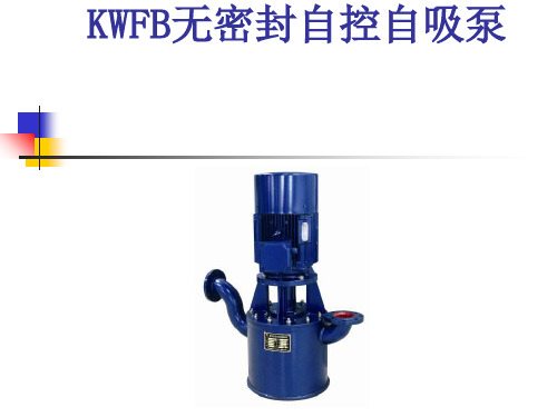
KWFB无密封自控自吸泵
KWFB产品应用场合
KWFB系列无密封自控自吸泵, 是我公司在 反复研究国内外同类产品的基础上,开发 成功的新产品。
该产品具有耐温、耐压、耐磨,“一次引 流,终身自吸”等多种功能与优点。在一 定条件下替代长轴泵、液下泵、潜水潜污 泵等设备。在石油、电力、化工、钢铁、 医药、焦化、电镀、环保、消防、市政、 净水、国防军工、纺织印染、采掘选矿、 民用建筑等行业中广泛应用,深受用户的 好评。
KWFB产品特点
1.采 用 优 化 设 计 的 “ 泵 用 连 环式多面离心动力密封装 置” ,革除了传统水泵的填 料密封、机械密封,彻底制 服了“跑、冒、滴、漏”。
2.可 靠 性 高 , 运 行中密封装置不 摩擦,使用寿命 较 同 类 产 品 长 10 倍以上,可靠性 高。增加了停机 密封装置,更加 适用于频繁起动 场合。
CW系列电涡流测功机使用说明书
CW 系列电涡流测功机使用说明书
1 主要用途
CW 系列电涡流测功机作为一种负载主要是用来测量动力机械各种特性的试验设备。本 机适用于内燃机、中、小型功率电机、汽车传动部件、燃气轮机、水轮机、工程机械、林业、 矿山、石油钻采等机械的性能试验,也可作为其它动力设备的吸功装置。
额定扭矩转速 r/min 2600 2600 2500 2400 2200 2400 2400 2500 2500 2500 2300 2000 1800 2000 1800 1900 1900 1900
最高转速 r/min 15000 14000 13000 13000 12000 12000 11000 10500 10000 9000 8500 8000 7000 6000 5000 4500 4000 3500
CW 系列电涡流测功机使用说明书
转动惯量 kgm2 0.002 0.003 0.01 0.02 0.05 0.1 0.18 0.32 0.52 1.2 1.8 2.7 3.6 5.3 7.0 10.1 13.3 16.2
最大励磁电压 V 90 90 90 90 90 90 90 120 120 120 120 120 120 120 180 180 180 180
6.1 台架基础.............................................................................................................................7 6.2 供水系统.............................................................................................................................8 6.3 测功器的校正...................................................................................................................10 7、测功器的使用........................................................................................................................... 11 8、维护保养...................................................................................................................................12 9、测功机安装尺寸一览表...........................................................................................................15 10、联轴器联接尺寸.....................................................................................................................17 11、滚动轴承一览表 ..................................................................................................................... 18 12、随机附件.................................................................................................................................18 13、售后服务.................................................................................................................................19
- 1、下载文档前请自行甄别文档内容的完整性,平台不提供额外的编辑、内容补充、找答案等附加服务。
- 2、"仅部分预览"的文档,不可在线预览部分如存在完整性等问题,可反馈申请退款(可完整预览的文档不适用该条件!)。
- 3、如文档侵犯您的权益,请联系客服反馈,我们会尽快为您处理(人工客服工作时间:9:00-18:30)。
Thick Film Chip Resistors, Industrial For technical questions contact: ff2bresistors@Document Number: 31011RCWPVishay DaleFEATURES•Operating temperature range: - 55°C to + 150°C•Same materials and construction as MIL-PRF-55342chip resistors•Termination: Tin/Lead wraparound termination overnickel barrier. Also available with Lead (Pb)-freewraparound terminations.•to customer requirements•Size, value, packaging and materials can be customized for special customer requirements.*Consult factory for extended resistance range.**Power rating depends on the max. temperature at the solder point, the component placement density and the substrate material.STANDARD ELECTRICAL SPECIFICATIONSGLOBAL MODEL HISTORICAL MODEL POWER RATING MAXIMUM OPERATINGTEMPERATURE COEFFICIENTTOLERANCE%RESISTANCE RANGE RCWP0402RCWP-04020.0425300100± 1 to ± 10± 1 to ± 10 5.62 - 1M 10 - 1M RCWP0603RCWP-06030.0750300100, 300± 2 to ± 10± 1 to ± 10 3 - 1M 5.62 - 1M RCWP0540RCWP-5400.0840300100, 300± 2 to ± 10± 1 to ± 10 3 - 4.7M 10 - 499K RCWP0550RCWP-5500.1050300100, 300± 2 to ± 10± 1 to ± 10 2 - 4.7M 5.62 - 1M RCWP0575RCWP-5750.1570300100, 300± 2 to ± 10± 1 to ± 10 2 - 10M 5.62 - 1M RCWP5100RCWP-51000.20100300100, 300± 2 to ± 10± 1 to ± 10 3 - 15M 5.62 - 1M RCWP1206RCWP-12060.25100300100, 300± 2 to ± 10± 1 to ± 10 3 - 15M 5.62 - 5.62M RCWP5150RCWP-51500.35125300100, 300± 2 to ± 10± 1 to ± 10 3 - 20M 5.62 - 4.75M RCWP1100RCWP-11000.50100300100, 300± 2 to ± 10± 1 to ± 10 3 - 7.5M 5.62 - 5.62M RCWP7225RCWP-72250.60200300100, 300± 2 to ± 10± 1 to ± 10 3 - 20M 5.62 - 15M RCWP2010RCWP-20100.80200300100, 300± 2 to ± 10± 1 to ± 10 3 - 20M 5.62- 15M RCWP2512RCWP-25121.0200300100, 300± 2 to ± 10± 1 to ± 105 - 20M 5.62 - 15MRCWPThick Film Chip Resistors, IndustrialVishay DaleDocument Number: 31011For technical questions contact: ff2bresistors@DIMENSIONSDIMENSIONS [in millimeters]GLOBAL MODEL A (Len g th)B (Width)C (Hei g ht)D(Top Term)E(Bottom Term)RCWP04020.039 ± 0.003[0.99 ± 0.08]0.020 ± 0.003[0.51 ± 0.08]0.013 ± 0.003[0.33 ± 0.08]0.010 ± 0.005[0.25 ± 0.13]0.010 ± 0.005[0.25 ± 0.13]RCWP05400.055 ± 0.005[1.40 ± 0.13]0.040 ± 0.005[1.02 ± 0.13]0.020 ± 0.005[0.51 ± 0.13]0.010 ± 0.005[0.25 ± 0.13]0.010 ± 0.005[0.25 ± 0.13]RCWP05500.055 ± 0.005[1.40 ± 0.13]0.050 ± 0.005[1.27 ± 0.13]0.020 ± 0.005[0.51 ± 0.13]0.010 ± 0.005[0.25 ± 0.13]0.015 ± 0.005[0.38 ± 0.13]RCWP05750.080 ± 0.005[2.03 ± 0.13]0.050 ± 0.005[1.27 ± 0.13]0.020 ± 0.005[0.51 ± 0.13]0.015 ± 0.005[0.38 ± 0.13]0.015 ± 0.005[0.38 ± 0.13]RCWP06030.063 ± 0.005[1.60 ± 0.13]0.032 ± 0.005[0.81 ± 0.13]0.018 ± 0.005[0.46 ± 0.13]0.012 ± 0.005[0.31 ± 0.13]0.015 ± 0.005[0.38 ± 0.13]RCWP11000.105 ± 0.005[2.67 ± 0.13]0.100 ± 0.005[2.54 ± 0.13]0.020 ± 0.005[0.51 ± 0.13]0.015 ± 0.005[0.38 ± 0.13]0.015 ± 0.005[0.38 ± 0.13]RCWP12060.125 ± 0.005[3.18 ± 0.13]0.063 ± 0.005[1.60 ± 0.13]0.020 ± 0.005[0.51 ± 0.13]0.015 ± 0.005[0.38 ± 0.13]0.015 ± 0.005[0.38 ± 0.13]RCWP20100.197 ± 0.006[5.00 ± 0.15]0.098 ± 0.005[2.49 ± 0.13]0.020 ± 0.005[0.51 ± 0.13]0.020 ± 0.005[0.51 ± 0.13]0.020 ± 0.005[0.51 ± 0.13]RCWP25120.250 ± 0.006[6.35 ± 0.15]0.124 ± 0.005[3.15 ± 0.13]0.020 ± 0.005[0.51 ± 0.13]0.020 ± 0.005[0.51 ± 0.13]0.020 ± 0.005[0.51 ± 0.13]RCWP51000.105 ± 0.005[02.67 ± 0.13]0.050 ± 0.005[1.27 ± 0.13]0.020 ± 0.005[0.51 ± 0.13]0.015 ± 0.005[0.38 ± 0.13]0.015 ± 0.005[0.38 ± 0.13]RCWP51500.155 ± 0.005[3.94 ± 0.13]0.050 ± 0.005[1.27 ± 0.13]0.020 ± 0.005[0.51 ± 0.13]0.015 ± 0.005[0.38 ± 0.13]0.015 ± 0.005[0.38 ± 0.13]RCWP72250.230 ± 0.005[5.84 ± 0.13]0.075 ± 0.005[1.91 ± 0.13]0.020 ± 0.005[0.51 ± 0.13]0.020 ± 0.005[0.51 ± 0.13]0.020 ± 0.005[0.51 ± 0.13]Legal Disclaimer NoticeVishayNoticeSpecifications of the products displayed herein are subject to change without notice. Vishay Intertechnology, Inc., or anyone on its behalf, assumes no responsibility or liability for any errors or inaccuracies.Information contained herein is intended to provide a product description only. No license, express or implied, by estoppel or otherwise, to any intellectual property rights is granted by this document. Except as provided in Vishay's terms and conditions of sale for such products, Vishay assumes no liability whatsoever, and disclaims any express or implied warranty, relating to sale and/or use of Vishay products including liability or warranties relating to fitness for a particular purpose, merchantability, or infringement of any patent, copyright, or other intellectual property right. The products shown herein are not designed for use in medical, life-saving, or life-sustaining applications. Customers using or selling these products for use in such applications do so at their own risk and agree to fully indemnify Vishay for any damages resulting from such improper use or sale.。
