Sika Grout 214产品说明
二次灌浆作业指导书
建投丰宁关道梁风电场项目二次灌浆作业指导书批准:年月日审核:年月日编写:年月日中国二十二冶集团丰宁关道梁风电场工程项目经理部年月日目录一、编制依据 (2)二、工程概述 (3)三、施工准备 (3)3.1机具准备 (3)3.2人员准备 (3)四、施工工序与工艺 (4)4.1施工工艺 (4)4.2施工方法 (4)五、施工要求 (5)六、注意事项 (6)七、安全文明施工的措施 (6)7.1安全文明施工组织机构 (6)7.2施工安全要求和环境条件 (6)一、编制依据建筑施工手册第四版电力建设施工质量验收及评价规程 DL/T 5210.1-2012 建筑工程施工质量验收统一标准 GB 50300-2013建筑地基基础工程施工质量验收规 GB 50202-2002工程建设标准强制性条文及应用示例 04DX002水泥基灌浆材料应用技术规 GB/T 50448-2015建设工程施工现场供用电安全规 GB 50194-2014施工现场临时用电安全技术规 JGJ 46-2005建筑施工安全检查标准 JGJ-2011电力建设安全工作规程 DL 5009.2-2013二、工程概述建投丰宁关道梁风电场项目48MW工程位于丰宁县北部万胜永乡,距丰宁县城直线距离约72km,距沽源县城约62km,东经116°14′~116°28′,北纬41°45′~41°54′,场址区域海拔高度1400~1600m,装机容量为50MW。
地貌属山地与丘陵相结合,地形起伏不大,地表多为草本植物。
主风向为西北西(WNW)风,风能资源较为丰富。
G111与G239从丰宁县经过,场区附近有S244通过,场区有乡村道路相连,交通较为便利。
建投丰宁关道梁风电场项目装机规模48MW,包括2.5MW 风机19台,一次性建成。
所有风机须在吊装前完成二次灌浆。
三、施工准备3.1机具准备3.2人员准备四、施工工序与工艺4.1施工工艺上锚板水平度复测→施工准备→清理设备基础→二十四小时前开始洒水湿润基底→灌浆料搅拌→灌浆施工→养护4.2施工方法4.2.1基础顶面清理1、将已凿毛的基础混凝土顶面进行彻底清理,用压缩空压机吹扫干净。
斯可络螺杆空气压缩机说明书.

斯可络螺杆空气压缩机产品使用说明书安全注意事项1.压缩空气和电都具有危险性。
在确保电源已经切断,整个压缩机系统里的压缩空气都已放空的情况下方能在机组上进行检修或维护保养。
安全注意:在起动前将压缩机接通非常短的时间(约1秒钟),检查旋转方向,必须确保空压机的旋转方向正确,否则短短几秒钟就有可能导致空气压缩机螺杆组的损坏。
2.在机组进行前,必须确保所有的接头,附件都已紧锁。
3.在机组运转时,不要松动,拆掉任何管路附件、接头和器件。
机组里充满高压高温的液体和气体,能引起严重的人身伤害事故。
4.引到压缩机的供电线上,必须安装空气开关,熔断丝等安全装置。
为了确保电器设备的可靠性,务必请按照有关的安全条例,接上合适的接地线,并在压缩机设备周围留出必要的维修空间。
5.压缩机不能在高于铭牌规定的排气压力下工作,否则电动机会过载,其结果导致电动车和压缩机停车。
6.只能使用安全溶液来清洗压缩机和辅助设备。
7.安全阀安装在油细分离器底座上,一旦系统中气体压力超过额定压力将通过此阀得以释放,与此同时务必检查超压原因。
8.在压缩机上做任何机械维修之前,必须做好下述几项准备工作;8.1 机组停车8.2 切断电源,手动切断开关,确保压缩机处于断电状态。
8.3 确保机组能压缩空气已经放空。
9.在压缩机开车以前,必须读懂这本维护使用手册。
本手册介绍了我公司螺杆压缩机的工作原理及其主要结构,尽可能地为操作人员提供压缩机关键部件的功能、操作、维护、保养等方面的知识,让用户最有效的使用该设备。
本公司产制的螺杆式压缩机于出厂前均已经过严密的质量控制及测试,但为了确保机器安全可靠的运转,并保持其耐久性,请于安装试车使用前熟读本使用说明书,充分掌握该压缩机的操作技能,使其处于良好的机械状态。
如因对本说明书之内容有不了解之处,或是您需要更详细的资料,请与本公司服务单位联络,我们将帮助您解决一切困难。
第一章螺杆式空压机通则及规范 (4)一、微油螺杆式空压机简介 (4)二、微油螺杆式空压机机体构造 (4)三、螺杆式压缩机压缩原理 (6)四、空压机技术规范及外形图 (8)第二章空压机安装 (15)一、安装 (15)二、配管、基础及冷却系统注意事项 (16)三、电器一般规范及安全规范 (19)第三章系统流程 (20)一、系统流程 (20)二、安全保护系统及警告装置 (28)三、控制系统及电气线路 (29)第四章操作 (33)一、试车、开机与停机 (33)二、开机前之检查 (34)三、运转中注意事项 (34)四、长期停机之处理方法 (35)第五章智能控制器 (37)一、使用条件 (37)二、工作原理及基本功能 (37)三、主要技术参数 (38)四、安装及接线 (39)五、使用及操作 (41)第六章保养与检查 (51)一、润滑油之规范及使用保养 (51)二、皮带调整 (52)三、压力系统之调整 (53)四、安全阀之调整 (54)五、油细分离器之更换步骤 (55)第七章保养与故障排除 (56)一、日常保养 (56)二、故障排除表 (58)三、螺杆式空压机运转记录表 (61)第一章螺杆式空压机通则及规范一、微油螺杆式空压机简介微油螺杆式压缩机具有运转性能可靠、易损件少、振动小、噪音低、效率高的特点。
SikaGrout 214

Sika Grout® 214 无收缩自流平灌浆料
简介
SikaGrout® 214 为无收缩自流平预拌型胶结灌浆料。其凝结时间稍长,以便在不同环 境温度下使用。
使用
优点 使用说明 表面预备 混合
SikaGrout 214 可在如下场合作为灌浆料使用: * 机床地基 * 预制构件 * 混凝土锚固 * 桥墩底座 * 洞穴,沟缝, 凹处等 * 任何需要填充的沟缝
机床灌浆:
彻底润湿,螺栓孔内无积水,尽可能行将锚固孔灌满,注意灌浆料是连续灌入。锚固螺栓与基面 的距离至少应是砂浆中骨料直径的 3 倍(缝宽最少 10 毫米) 大体积地基灌浆:
根据其体积,可先用较大的石子如:4~8 毫米。8~16 毫米或 16~32 毫米,同时加入到本灌浆料 中。其比例在 50~100%之间,卵石较碎石好。可振动使其得到良好的密实性。
瑞士西卡建筑材料服务商 倍耐基系统建材(昆山)有限公司 江苏省昆山市庆丰西路 696 号 电话:0512-5703 6866 传真:0512-5703 6667
Sika Grout ® 214 2/2
注意
关于西卡产品的应用和最终使用的建议,均基于西卡对于正常条件下储存、处理和使用西卡 产品时的知识和经验所善意提供的。鉴于实际使用中的物料、底层和工地存在各种差异,所 以本信息,或者任何书面建议,或者任何其他建议,并不意味着对商品性或者任何特定目的 适用性的担保,也不意味着任何法律责任的承担。应尊重第三方财产权。所有定单均须遵循 西卡当前的销售及交付条款。使用者应当始终参考相关产品技术说明书中最适合的条款,如 有要求,西卡公司非常乐意提供。
用 Antisol E 养护暴露在外面的表面。
swagelok

(38.9)
1.53
(63.5)
2.50
25/32 面板孔
(19.8)
0.19 (4.8) 最大面板 厚度
SWAGELOK
B A
所示尺寸是世伟洛克卡套管接头螺母用手指旋紧时的尺寸。 ➀ 可订购带有两种不同端接的 SK 系列阀。 关于订购信息可与您当地授权的世伟洛克公司代表联系。 ➁ 参阅规范 ISO 7/1、 BS EN 10226-1, DIN-2999 和 JIS B0203。 ➂ 标准阀门上的 VCO 接头包括低温碳氟化合物 FKM O-型圈。
316 SS / A479 PTFE 基 具有烃粘合剂涂层的二硫化钼
13 15 18
订购信息与尺寸
选择一个订购号。 以 in. (mm) 为单位表示的尺寸仅供参考, 可能有变动。
端接➀ 类型 世伟洛克 卡套管接头 内螺纹 NPT 内螺纹 ISO➁ 外螺纹 NPT 外螺纹 VCO 接头➂ 尺寸 1/4 in. 3/8 in. 6 mm 8 mm 1/4 in. 1/4 in. 1/4 in. 1/4 in. 订购号 SS-4SKPS4 SS-4SKPS6 SS-4SKPS6MM SS-4SKPS8MM SS-4SKPF4 SS-4SKPF4RT SS-4SKPM4 SS-4SKPVCO4 Cv 1.3 1.4 1.3 1.3 1.2 1.2 1.1 0.9 0.188 (4.8) 孔径 尺寸, in. (mm) A 3.60 (91.4) 3.73 (94.7) 3.60 (91.4) 3.68 (93.5) 2.91 (73.9) 2.91 (73.9) 3.23 (82.0) 3.15 (80.0) B 1.80 (45.7) 1.86 (47.2) 1.80 (45.7) 1.84 (46.7) 1.46 (37.1) 1.46 (37.1) 1.62 (41.1) 1.58 (40.1)
YK-214无线系列智能开关量记录仪使用说明书

YK-214无线系列智能开关量记录仪使用说明书北京宇科泰吉电子有限公司一、概述YK-214LCD系列智能无线开关量记录仪,采用先进的微电脑芯片及技术,与现场的无线开关发射器配套使用,对现场开关量信号、电平信号进行测量显示、存储及现场查询,可以通过移动硬盘导出数据用Excle文件软件打开查询,浏览等。
YK-214LCD系列智能无线开关量仪表可以对多套设备运行进行时间监测、记录等,并能根据系统时间把开关量的闭合、断开时间记录下来。
用来记录设备的开关次数与开关时间,通过按键浏览记录数据。
每路开关量可以记录3万组数据,数据包含开关量动作的时间(年月日)、状态,数据记录采用先进先出循环记录方式。
仪表内置硬件时钟,停电不影响时钟运行。
YK-214LCD智能无线开关量记录仪可根据客户要求做成脉冲信号,TTL电平信号、SSI编码器信号输入的记录仪,可带RS232或RS485的通讯接口与PLC,计算机等现场工业设备连接构成工业测控系统。
仪表内部带有可充电电池供时钟运行,仪表长期不使用时建议每六个月通电24小时使电池充电。
二、主要技术指标1·输入信号:无源开关量接点,脉冲信号,TTL电平等2·显示方式:宽温蓝屏白字高亮LCD显示屏。
3·记录数据容量:每通道可记录存储30000条。
4·报警输出:仪表可以带多达16个继电器报警输出,220V/3A。
(订货说明)5·通讯输出:隔离通讯接口RS485(标准Modbus-RTU通讯协议)波特率1200~9600bps内部自由设定6·工作环境:温度0~50℃湿度<85%RH7·电源:开关电源85~265V AC或DC24V 功耗<4W8·外形尺寸:160×80×120mm(盘装横式) 80×160×120mm(盘装竖式)320×120×270mm(台式)可带串行通讯接口,可与各种带串行接口的设备进行双向通讯,组成网络控制系统。
SikaGrout 214

Product Data Sheet Edition 2011-10_1 SikaGrout ®-214C o n s t r u c t i o nSikaGrout ®-214Multi-purpose dual shrinkage compensated cementitious groutProduct DescriptionSikaGrout ®-214 is a dual-shrinkage compensated self-levelling, premixedcementitious grout with extended working time to suit local ambient temperatures. UsesSikaGrout ®-214 is suitable for the following grouting works with clearance of 10 mm or more:⏹ Machine foundations⏹ Columns in precast constructions ⏹ Concrete anchors ⏹ Bridge bearings ⏹ Cavities ⏹ Gaps ⏹ Recesses ⏹ Rail bedsCharacteristics / AdvantagesSikaGrout ®-214 is an economical and easy to use material requiring the simple addition of water. Other beneficial properties are: ⏹ Easy to mix and apply ⏹ Good flow characteristics ⏹ Rapid strength development ⏹ High ultimate strength ⏹ Impact resistant ⏹ Non-corrosive ⏹ Non-toxic⏹ Iron and chloride free⏹ Dense and non-shrink (2-step expansion) ⏹ Extended working timeProduct DataFormAppearance / Colour Grey premixed powder Packaging25 kg bagsStorageStorage Conditions / Shelf Life6 months from the date of production if stored properly in original, unopened and undamaged sealed packaging in dry conditions. Protect from direct sunlight.Technical DataDensity ~ 2.2 kg/ltr (depending on consistency and temperature) Aggregate Size 3.3 mm max.Layer Thickness100 mm max. per pour / 10 mm min. per pourMechanical / Physical PropertiesCompressive Strength ~ 60 N/mm 2 (at +25°C / 28 days) Typical ResultsTests carried out at +25°CMix DesignsFlowable (Water content 4.2 ltr/25 kg)Pourable (Water content 3.8 ltr/25 kg) Stiff(Water content 3.2 ltr/25 kg)Flow BS Cone JA Cone 300 mm 15 seconds 270 mm 17 seconds 180* mm N/A Initial setting time 4 h : 30 m 3 h : 40 m 3 h : 00 m Bleeding at 24 hours 0 % 0 % 0 % Expansion at 24 hours0.70 %0.30 %0.07 %Compressive strength 1 day 3 days 7 days 28 days ~25 N/mm 2~40 N/mm 2~50 N/mm 2~60 N/mm 2~32 N/mm 2~42 N/mm 2~53 N/mm 2~70 N/mm 2~35 N/mm 2~45 N/mm 2~58 N/mm 2~75 N/mm 2Flexural strength 7 days 28 days ~6.2 N/mm 2~7.4 N/mm 2~6.5 N/mm 2~8.1 N/mm 2~7.3 N/mm 2~8.5 N/mm 2* after 15 strokesThe above tests were conducted under laboratory conditions in accordance with the following standards: ⏹ Initial setting ASTM C 191 ⏹ Bleeding & Expansion ASTM C 940 ⏹ Compressive strength ASTM C 109 ⏹ Flexural strength BS 4551The results above are typical data and given as a guide only. Site results may differ according to mixing process, placing, curing, etc. Preliminary tests are always recommended.Fire ResistanceFire rating, Classified A1 - SikaGrout ®-214 will not contribute in any state of the fire including the fully developed fire. (EN 13501-1)System InformationApplication DetailsTypical YieldFlowable consistencySikaGrout ®-214 1.80 kg 25 kg 72 x 25 kg bagWater0.30 ltr 4.2 ltr 302 ltr Volume Mortar1 ltr13.9 ltr1 m 3Pourable consistencySikaGrout®-214 1.90 kg 25 kg 76 x 25 kg bagWater 0.3 ltr 4.0 ltr 303 ltrVolume Mortar 1 ltr 13.2 ltr 1 m3Substrate Quality Concrete, mortar and stoneSurfaces must be sound, clean, and free from frost, oils, grease, standing waterand all loosely adhering particles and other surface contaminants.Metal surfaces (iron and steel)Surfaces should be clean, free from scale, rust, oil and grease.Substrate Preparation The substrate should be prepared by suitable mechanical preparation techniquessuch as high pressure water, breakers, grit blasting, scabblers, etc.All absorbent surfaces must be well saturated with clean water, but be free of anysurface water or puddles prior to the application of SikaGrout®-214.Application Conditions /LimitationsApplication Temperature +10°C min. / +40°C max.Application InstructionMix Ratio Consistency Water (ltr) per 25 kg of GroutFlowable 4.0 – 4.4Pourable 3.6 – 4.0Stiff 3.0 – 3.4 for special application such as anchoring starter bars Mixing Place 70% - 80% of the premeasured clean water (depending on consistencyrequired – refer to “Mix Ratio”) into a clean container and gradually add the wholebag of SikaGrout®-214 into it while continuously mixing. Add the remaining wateruntil the desired consistency is obtained.Mixing Time Mix for 2 – 3 minutes with a low speed drill (500 rpm max.).Application Method / Tools Use SikaGrout®-214 for grouting only.After mixing, stir lightly with a spatula for a few seconds to release any entrapped air. The grout is then poured immediately into the prepared formwork.When carrying out baseplate grouting, ensure sufficient pressure head it maintained for uninterrupted mortar flow. For formwork repair, the prepared formwork must be firmly in place and kept watertight.When placing grout over a large area, it is important to maintain a continuous flow throughout. Work sequence must be properly organised to ensure an uninterrupted flow.For sections thicker than 100 mm or for grouting large areas, it is necessary to mix SikaGrout®-214 with graded 10 mm silt free aggregates to minimise temperature rise generated during curing stage. The quantity of aggregates should not exceed 1 part aggregates to 1 part SikaGrout-®214 by weight. Other precautions such as the use of chilled water, insulation of the formwork or baseplate may be required. Please consult our Technical Service Department for assistance.To further ensure that air entrapped during mixing is allowed to fully escape, it may be necessary to make breather holes. Use steel rods or chains to assist the flow of grout where necessary.Cleaning of Tools Clean all tools and application equipment with water immediately after use.Hardened and/or cured material can only be mechanically removed.Notes on Application / LimitationsAt temperatures +20°C and below, setting time and strength development will be slower.Non-shrink grout contains additives which expand either during the plastic stage and / or the hardening stage to compensate for the shrinkage of the cementitious matrix. However, this ‘non-shrink’ property will be effective only if the material is not subjected to water loss.This is confirmed by a note in the ASTM C 1107 Standard Specification for packaged dry, hydraulic cement grout (non-shrinkable), which clarifies the behaviour of the non-shrink grout when subjected to some drying:“Note 1: Since all conditions of use cannot be anticipated, this specification requires non-shrink grout to exhibit no shrinkage when tested in a laboratory-controlled moist-cured environment, and requires only the reporting of theobserved height change, usually shrinkage, when test specimens are subject to some degree of drying.”Curing DetailsCuringIf formwork type repair is used, leave the formwork in place for at least 3 days. Upon removal of the formwork, cure the exposed surfaces immediately with Antisol ®-E curing compound or use other approved curing methods.Value Base All technical data stated in this Product Data Sheet are based on laboratory tests. Actual measured data may vary due to circumstances beyond our control.Health and Safety InformationFor information and advice on the safe handling, storage and disposal of chemical products, users shall refer to the most recent Material Safety Data Sheet (available on request) containing physical, ecological, toxicological and other safety-related data.Legal NotesThe information, and, in particular, the recommendations relating to theapplication and end-use of Sika products, are given in good faith based on Sika's current knowledge and experience of the products when properly stored, handled and applied under normal conditions in accordance with Sika’s recommendations. In practice, the differences in materials, substrates and actual site conditions are such that no warranty in respect of merchantability or of fitness for a particular purpose, nor any liability arising out of any legal relationship whatsoever, can be inferred either from this information, or from any written recommendations, or from any other advice offered. The user of the product must test the product’s suitability for the intended application and purpose. Sika reserves the right to change the properties of its products. The proprietary rights of third parties must be observed. All orders are accepted subject to our current terms of sale and delivery. Users must always refer to the most recent issue of the local Product Data Sheet for the product concerned, copies of which will be supplied on request.C o n s t r u c t i o nSika Singapore Pte Ltd200 Pandan Loop, 06-02 Pantech 21Singapore 128388 SINGAPOREPhone: +65 6777 2811Fax: +65 6779 6200 e-mail: info@ .sgSika Kimia Sdn BhdLot 689 Nilai Industrial Estate 71800 Nilai, Negeri Sembilan DK MALAYSIAPhone: +606-7991762 Fax: +606-7991980 e-mail: info@ .my。
SikaCor EG-System Rapid产品技术说明书

产品技术说明书出版 03/03/2012 CNSikaCor ®EG-System RapidC o n s t r u c t i o nSikaCor ® EG-System Rapid (SikaCor ® EG-System Rapid)快速固化环氧树脂+聚亚安脂产品简介SikaCor Zinc R Rapid : 2组份多颜色快速固化的富锌环氧树脂底涂。
SikaCor EG Phosphate Rapid :2组份快速固化环氧树脂底涂,含富锌磷酸盐活性颜料。
SikaCor EG 1 Rapid :2组份含云母的氧化铁环氧树脂中间涂层。
SikaCor EG 4/5:2组份RAL 和DB 颜色聚亚安脂外涂加入1% b.w.SikaCor PUR Accelerator( 请见技术使用说明书活动更多资料 ),表面可快速干燥并达到完全固化获得German standard …TL/TP-KOR Stahlbauten“, page 97认证。
应用 对钢材有强力持久的抗腐蚀作用以及装饰效果。
该系统尤其适用于低温环境和车间。
需要每天施工3次。
优点该涂层系统结合了环氧树脂在底涂和中间涂层的极好的耐腐蚀性能以及聚亚安脂外涂。
⏹ 快速外涂 ⏹ 每天上3次涂层⏹ 坚韧的弹性和密度,但不易损坏 ⏹ 抗震动和冲击 ⏹ 快速固化 ⏹ 适用于低温⏹ 能耐受最大至+150°C 的温度产品数据级别和颜色SikaCor Zinc R Rapid 锌灰色SikaCor EG Phosphate Rapid 沙黄色, 约RAL 1002 和 红棕色, 约RAL 8012 SikaCor EG 1 Rapid 灰色, 约DB701, DB702, DB703; 绿色,约DB601; 白色, 约DB701SikaCor EG 4 金属色 SikaCor EG 5 RAL 颜色 SikaCor Cleaner 25, 160 升 由于原料的变化,不同批号之间可能会有轻微色差包装SikaCor Zinc R Rapid 26kg 净重SikaCor EG-Phosphate Rapid 28.5kg净重SikaCor EG 1 Rapid 28.5kg净重SikaCor EG 4 30; 12.5和3kg*净重SikaCor EG 5 25; 10和3kg*净重Thinner EG 25; 10和3L( *为某些颜色的最小数量 )保质原装密封容器内,在干燥和凉爽的环境中:SikaCor Zinc R Rapid 1年SikaCor EG Phosphate Rapid 3年SikaCor EG 1 Rapid 3年SikaCor EG 4, SikaCor EG 5 2年SikaCor Zinc R 1年SikaCor EG-Phosphate, SikaCor EG 1 3年SikaCor EG 4, SikaCor EG 5; 2年使用指南涂层系统钢材:3层系统1 X SikaCor EG Phosphate Rapid 或1 X SikaCor Zinc R Rapid1 X SikaCor EG 1 Rapid1 X SikaCor EG 4或 SikaCor EG 54层系统针对极度暴露情况1 X SikaCor EG Phosphate Rapid 或 1 X SikaCor Zinc R Rapid2 X SikaCor EG 1 Rapid1 X SikaCor EG 4 或 SikaCor EG 5在长期处于水下或冷凝环境中底涂只能用SikaCor Zinc R Rapid镀锌表面和铝:1 X SikaCor EG 1 Rapid1 X SikaCor EG 4或 SikaCor EG 5为达到最佳的不透明性,当使用亮色的SikaCor EG 5 时,必须再上一遍涂料表面处理钢材:按照EN ISO 12944, part 4标准,喷砂至 Sa 2 1/2。
Turck 旋转速度监测器 IM21-14EX-CDTRI 产品说明书

T 21:49:33+02:00The rotation speed monitor IM21-14EX-CDTRI monitors frequencies, rotation speeds and pulse trains of rotating motor, gear or tur-bine parts according to over or undershoot of adjusted limit values. The current value is indi-cated on a display on the front of the device.Intrinsically safe sensors acc. to EN60947-5-6 (NAMUR) can be connected. The line is monitored for wire-break and/or short-circuit depending on the setting. In the event of an input circuit error the relays drop out,the transistor is blocked and the Pwr LED changes to red.The device can be configured andparametrized via PC (FDT/DTM) ; the appro-priate TURCK-PROG III transmission cable is available from TURCK. A basic scope of pa-rameters can be set via buttons and display on the front or remotely via the current inter-face and HART®.At each of the two relay outputs a predefined limit value can be monitored. The two relays also monitor overshoot/undershoot of window limits. The transistor output can also be used as a pulse divider. The measured value is per-manently written to a ring buffer with space for 8000 values. The writing process is stopped with a predefined trigger event, like for ex-ample "excess of limit value". After that, the stored signal sequence can be read out.A switching hysteresis is defined by setting a switch-on and off point. A switch-off delay can also be set to avoid shut down due to sudden frequency hops.■ATEX, IECEx, FM , TR CU, NEPSI, TIIS■Installation in zone 2■Monitors over and underrange of limit values and window limits ■Operating range 0.06 … 600000 min■Control of sensors acc. to EN 60947-5-6(NAMUR)■ 2 x relay outputs and 1 x transistor out-put ■Current output 0/4…20 mA reversible ■Pulse output Ex nL II C/II B■Parametrized via PC (FDT / DTM), front-panel switch or HART®■Complete galvanic isolationT 21:49:33+02:00Type code IM21-14EX-CDTRI Ident no.7505651Nominal voltage Universal voltage supply unit Operating voltage 20…250 VAC Frequency40…70 Hz Operating voltage range 20…125 VDC Power consumptionð 3 WMonitoring range / setting range:ð 0.06…600000 min Max. input frequency 600000 min Pulse time ï 0.02 ms Pulse stop ï 0.02 msNAMUR input NAMUREN 60947-5-6No-load voltage 8.2 VDC Short-circuit current 8.2 mA Input resistance 1 k òCable resistance ð 50 òSwitch-on threshold 1.75 mA Switch-off threshold1.55 mA Wire breakage threshold ð 0.06 mA Short-circuit thresholdï 6.4 mAOutput current0/4...20 mA Load resistance, current output ð 0.6 k òFault current0 / 22 mA adjustable Output circuits (digital) 2 x relays (NO)Relay switching voltage ð 250 VAC/30 VDC Switching current per output ð 2 ASwitching capacity per output ð 500 VA/60 W Switching frequency ð 10 Hz Contact qualityAgNi, 3µ AuSemicondutor output circuit(s)Output circuits (digital) 1 x transistor (potential-free, short-circuit proof)Switching voltageð 30 VDC Switching current per output ð 50 mA Switching frequency ð 10000 Hz Voltage drop ð 2.5 V Pulse output Voltage ð 30 V Currentð 10 mAMeasuring accuracy ð 0.05 % of full scale Reference temperature23 °CTemperature drift analog output 0.0025 %/KGalvanic isolation Test voltage2.5 kVDimensionsOutput relay – Load curveOutput relay – Electrical lifetimeT 21:49:33+02:00Important noteFor safety applications the values specified in the safety manual or the relevant Ex certificates (ATEX,IECEx, UL, etc.) apply.Ex approval acc. to conformity certificate IBExU 07 ATEX 1132Application areaII (1) G, II (1) Dignition protection category [Ex ia Ga] IIC , [Ex ia Da] IIICMax. values:Terminal connection: 1+2 / 6+7 / 9+10Max. output voltage U ð 9.6 V Max. output current I ð 10.7 mA Max. output power P ð 25 mW Internal resistance R 900 òCharacteristic linearMax. values:Terminal connection: 6+7Max. input voltage U ð 20 V Max. input current I ð 21.3 mA Max. input power P ð 400 mW Internal inductance/capacitance L /C negligibly small External inductance/capacitance L /C Ex ia IIC IIB L [mH]100 5.010.01100510.01C [µF]0.510.84 1.2 3.62.74.46.326Ex approval acc. to conformity certificate IBExU 07 ATEX B010 X Application area II 3 GProtection type Ex nA nC [ic Gc] IIC/IIB T4 GcMax. values:Terminal connection: 1+2 / 6+7 / 9+10Max.output voltage U ð 9.6 V Max. output current I ð 10.7 mA Max. output power P ð 25 mW Internal resistance R 900 òCharacteristic linearMax. values:Terminal connection: 6+7Max. input voltage U ð 20 V Max. input current I ð 21.3 mA Max. input power P ð 400 mW Internal inductance/capacitance L /C negligibly small External inductance/capacitance L /C Ex ic IIC IIB L [mH]100 5.010.01100510.01C [µF]0.7651.2 1.8 5.44.06.69.439IndicationOperational readiness green Pulse input yellow Error indicationredIP RatingIP20Flammability class acc. to UL 94V-0Ambient temperature -25 …+70 °C-25 ... +60 °C für FM Storage temperature -40…+80°C Relative humidity ð 95 %Dimensions 104 x 27 x 110 mm Weight249 gMounting instruction for DIN rail / panel Housing material polycarbonate/ABSElectrical connection4 x 5-pin removable terminal blocks, reverse polarity protected, screw connection Terminal cross-section 1 x 2.5 mm / 2 x 1.5 mm Tightening torque0.5 NmT 21:49:33+02:00AccessoriesType codeIdent no.DescriptionDesignIM-CC-5X2BU/2BK7504031Cage clamp terminals for IM modules (Ex-devices with 27mm overall width); includes: 2 pcs. 5-pin blue terminals and 2pcs. 5-pin black terminals.IM-PROG III 7525111The programming adapter IM-PROG III is used forparametrization of TURCK IM devices via FDT/DTM. In addi-tion, the in-PROG III provides galvanic isolation.。
DO-214AC中文资料

5.10 5.60 0.201 0.220
4.05 4.60 0.159 0.181
3.30 3.95 0.130 0.156
0.75 1.60 0.030 0.063
2.3
1.52
2.75
1.52
Ordering type Marking
STPS1L30U
G23
STPS1L30A
GB3
Band indicates cathode Epoxy meets UL94,V0
SMA STPS1L30A JEDEC DO-214AC
SMB STPS1L30U JEDEC DO-214AA
DESCRIPTION
Single Schottky rectifier suited to Switched Mode Power Supplies and high frequency DC to DC converters, freewheel diode and integrated circuit latch up protection.
8
6
4
2
IM
t
δ=0.5
0 1E-3
1E-2
t(s) 1E-1
Ta=25°C Ta=50°C Ta=100°C
1E+0
Fig. 2: Average forward current versus ambient temperature (δ=0.5).
IF(av)(A) 1.2 1.0 0.8 0.6
IR(mA) 1E+2
1E+1
1E+0
1E-1
1E-2
1E-3
0
5
Tj=150°C Tj=125°C Tj=100°C
风机基础二次灌浆技术交底

安全技术交底记录
共2页第1页编号:HNHD-FJJC-00
工程名称
风电工程
单位工程
风力发电机组工程
分部工程
风机基础
分项工程
基础二次灌浆
技术交底人
被交底负责人
领导签名
交底级别
三级
交底地点
项目部办公室
交底日期
2018年4月9日
参加
交底
人员
姓名
签名
日期
姓名
签名
日期
姓名
签名
日期
交
底
记
录
风机基础二次灌浆安全技术交底
一、概述:
牛郎山风电场拟安装单机容量为3.0MW的明阳MySE3.0-135风机工16台,总装机容量48.0MW。风机基础采用预应力锚栓组合件现浇钢筋混凝土基础。主体混凝土浇筑完成后3天可灌浆施工,灌浆料的选用、施工、养护应按《水泥基灌浆材料应用技术规范GB7130448-2008》执行。二次灌浆材料类别为Ⅱ类。灌浆料采用西卡SikaGrout214。抗压强度≥80MPa,抗弯强度≥10MPa。流动度初始值≥34cm,30分钟保留值≥31cm,抗冻等级F150,要求无收缩、自流平、无毒性、防腐锈蚀性,灌浆料厚度允许偏差±10mm,应连续施工。
5、灌浆完成后,应将表面压平压光,并用土工布覆盖,洒水养护7天。灌浆料达到设计强度后表面涂普通环氧煤沥青,干膜厚度不小于300um。
三、灌浆工艺控制
1、根据施工现场与技术规范要求,基础灌浆搅拌地点设置在灌浆施工现场,每一包(25kg粉料)建议加水量为 3.6-3.9L 先把 70-80%预先称重好的干净水加入到一干净容器中,然后不断搅拌的同时慢慢加入整包的 Sika grout 214。然后再加入剩余的水并继续低速(最大 800rpm)搅拌 2-4 分钟,直到混合均匀。停止搅拌,保持现状 1-2 分钟,然后再继续低速搅拌 1-2 分钟。
风机锚栓基础二次灌浆表面微裂纹处理探讨

风机锚栓基础二次灌浆表面微裂纹处理探讨【摘要】二次灌浆表面的裂纹是我们在施工中经常会遇到的,本文通过对风机锚栓基础表面的微裂纹进行检查,对微裂纹产生的原因进行了分析,对防治措施进行了探讨,对表面裂纹宽度、深度进行了测量,提出了相应的微裂纹的处理措施。
【关键词】二次灌浆;裂纹;防治混凝土表面的裂纹一直是施工过程中控制的重点,在施工过程中总是有各种各样的裂纹,其中有些裂纹是不影响工程结构的,而有些裂纹就有可能造成工程的结构破坏,因此,我们在工程施工中需严格控制裂纹的产生,特别是贯穿性的、影响工程质量的裂缝。
对于风机这种高耸建筑物,基础二次灌浆层的微裂纹控制将尤为重要,如果形成结构性的裂纹将影响整个基础的使用寿命,本文将结合风电场风机基础二次灌浆的情况,对二次灌浆表面的微裂纹产生的原因进行分析并提出应对措施。
1 风机基础二次灌浆概述由于传统基础环连接方式的风机基础在基础环四周易造成混凝土疲劳破坏及基础环下口混凝土浇筑不易密实等问题,同时由于基础环连接方式埋入混凝土中的部分是一个刚性结构,而露出部分及整个塔筒又是一个柔性体,在基础环与混凝土基础最上面的交线处就形成了一个刚性结构与柔性体交接处的应力集中部位,风机机组越来越高,受力状况越来越大、越来越复杂,在该交接处的混凝土就更容易形成应力破坏,基础环也更易形成应力变形,从而发生风机倒塌的安全事故,为了更好的保证风机基础的安全运行,防止基础的应力破坏,一种更合理的锚栓基础连接形式产生,该种连接形式不会在混凝土基础上面形成应力集中,同时该种连接形式使上下锚板对钢筋混凝土施加预压应力,使混凝土基础在任何受力状态下均处于受压状态,混凝土基础不易产生裂缝,使其耐久性得到提高。
为了保证风机基础上锚板的水平度,在设计及施工过程中,往往对上锚板进行二次调平,在调平结束后,在锚板下部进行二次灌浆,而该部分二次灌浆易在表面形成裂缝。
2 产生的原因锚栓连接的风机基础一般采用圆台式风机基础,一般会在上锚板下部开槽灌浆或直接在基础顶面进行灌浆,在目前使用的基础顶面的锚板直径大约在4.3-4.5m左右,锚板宽度约500mm,锚板下面的灌浆厚度约80mm左右,为了便于进行二次灌浆,一般设计上均会在锚板两侧留设80mm左右的便于灌浆的距离,同时为了保证灌浆强度和密实度,使用的二次灌浆的材料基本上都是定型的质量较好的高强度的灌浆材料,但是在二次灌浆后,在锚板的外侧极易形成环向的45°裂缝,同时在径向也会形成裂缝,这些裂缝形成主要有以下原因:2.1养护不到位:二次灌浆结束后,未及时采取措施进行养护,灌浆料表面的水分急剧蒸发,造成了灌浆料表面的干缩裂缝,经过现场的实际施工测试,在二次灌浆45分钟--1小时时,二次灌浆表面已干缩变硬,但内部仍然没有初凝,当对表面轻轻按压后,二次灌浆表面就会形成径向的裂缝,而在施工结束后,有些施工单位不进行养护或者养护时间过迟,从而造成了表面裂缝。
西卡材料Sikacrete-214说明.pdf
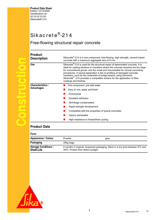
Product Data Sheet Edition 12/12/2005 Identification no: 02 03 02 03 05 Sikacrete®-214Sikacrete®-214Free-flowing structural repair concreteProduct DescriptionUseConstructionSikacrete®-214 is a one component, free-flowing, high strength, cement based concrete with a maximum aggregate size of 9 mm. Sikacrete -214 is used for the structural repair of deteriorated concrete. It is ideal for casting sections or members where the volumes required are too large for conventional grouts, and too small and inaccessible for normal concreting procedures. A typical application is the re-profiling of damaged concrete members, such as the underside of bridge beams, using formwork. Sikacrete® -214 provides a compatible surface for the application of Sika coatings and finishes. One component: just add water Easy to mix, apply and finish Economical Excellent adhesion Shrinkage compensated Rapid strength development Compatible with the properties of typical concretes Vapour permeable High resistance to freeze/thaw cycling®Characteristics / AdvantagesProduct DataForm Appearance / Colour Packaging Storage Conditions / Powder 25kg bags 6 months in original, unopened packaging. Store in a dry area between 5ºC and 40ºC. Protect from direct sunlight. greyShelf-Life1Sikacrete®-2141/4.Technical DataChemical base Density Layer Thickness Cement, Crystalline free Silica, aggregate and additives 2,3 - 2,4 kg/litre Min. 25mm - max. 200mm Property Compressive Strength Age days 1 7 28 Flexural Strength 1 7 28 Tensile Strength 28 N/mm2 34,0 55,0 75,0 3,8 5,7 7,5 5,5Mechanical PropertiesSystem InformationSystem StructurePrimers: Sika Monotop® 610 or SikaTop ArmaTec® 110 EpoCem® Repair Mortar: Sikacrete® -214 (25 – 200 mm layer thickness)Application DetailsConsumption / Dosage Mixing Procedures Volume Yield: 11,0 litres per 25kg bag Mixing can only be achieved using either a slow speed drill (set at 400 - 600 rpm) fitted with a clean, rust free, mixing paddle, or standard mortar or concrete mixing equipment. DO NOT ATTEMPT TO MIX BY HAND. Add 3,0 -3,12 litres of water to a suitable mixing vessel and then add Sikacrete® 214 slowly whilst mixing. Mix for at least 5 minutes until the larger aggregate has thoroughly dispersed and a uniform, free-flowing consistency is obtained. Substrate Quality The concrete substrate must be sound and of sufficient compressive strength (min. 20 N/mm² (MPa) with a minimum pull off strength of 1.5 N/mm² (MPa). The surface must be dry and free of all contaminants such as oils, grease, coatings, surface treatments, etc. The substrate must be prepared mechanically to remove cement laitance and achieve a profile open textured surface. Weak concrete should be removed and surface defects such as honeycombed areas; blowholes and voids must be fully exposed. Repairs to substrate, filling of blowholes/voids and surface levelling should be ® ® carried out using the appropriate product from the Sikafloor , Sikadur and ® Sikagard range of materials. Substrate Preparation All surfaces must be clean, sound and properly cured. Remove all loose material mechanically, with a wire brush, or by water or sand blasting. Embedded reinforcing steel should be free from scale, rust, oil and grease, and treated with ® ® a suitable protective coating such as SikaTop Armatec 110 EpoCem . The ® application of a suitable bonding agent, such as Sikadur -32 ZA or SikaTop Armatec® 110 EpoCem®, is recommended to improve adhesion on large areas or where particularly dense concrete substrates are involved. Ensure that the formwork is grout tight and that sufficient hydrostatic head is available to allow the mixed Sikacrete® -214 to flow into every extremity. If required, formwork can be sealed with Sikacryl® -S.Forming2Sikacrete®-2142/4Application Conditions / LimitationsSubstrate Temperature Ambient Temperature Pot Life Min 5°C – Max 30°C Min 5°C – Max 35°C Approximately 20 minutes.Application InstructionsMixing (Ratio/Dosage) 3,0 -3,12 litres per 25kg bag. Pour clean water in the correct proportion into a clean mixing vessel. Add the ® Sikacrete -214 slowly while mixing continuously. To avoid entraining too much air use a slow speed mixer (max. 500 rpm) for minimum of 3 minutes. By gradually adding the powder in portions, the desired application consistency can be obtained.Application Method / ToolsDampen the surface thoroughly with clean water prior to the application of Sikacrete® -214. Place the mixed Sikacrete® -214 directly after mixing ensuring that any displaced air is allowed to escape. Maintain sufficient hydrostatic head to keep the product flowing. Protect from rain until initial set has been achieved.Curing DetailsCuring Where ambient conditions may lead to rapid surface drying, the use of light water fogging for 48 hours or suitable water based curing compound is recommended. (Do not commence fogging until initial set has been reached; typically 1 - 2 hours depending upon ambient conditions). Please note that as a result of specific local regulations the performances of this product may vary from country to country. Please consult the local Product Data Sheet for the exact description of the application fields.Local RestrictionsHealth and Safety InformationProtective Measures Ecology Transportation Class Important Notes Residues of material must be removed according to local regulations. Fully cured material can be disposed of as household waste under agreement with the responsible local authorities. Detailed health and safety information as well as detailed precautionary measures e.g. physical, toxicological and ecological data can be obtained from the Material Safety Data Sheet. Toxicity Cement containing material may cause skin irritation. Wear gloves and goggles or apply barrier cream to hands while working with the mortar.3Sikacrete®-2143/4Legal NotesThe information, and, in particular, the recommendations relating to the application and end-use of Sika products, are given in good faith based on Sika's current knowledge and experience of the products when properly stored, handled and applied under normal conditions in accordance with Sika’s recommendations. In practice, the differences in materials, substrates and actual site conditions are such that no warranty in respect of merchantability or of fitness for a particular purpose, nor any liability arising out of any legal relationship whatsoever, can be inferred either from this information, or from any written recommendations, or from any other advice offered. The user of the product must test the product’s suitability for the intended application and purpose. Sika reserves the right to change the properties of its products. The proprietary rights of third parties must be observed. All orders are accepted subject to our current terms of sale and delivery. Users must always refer to the most recent issue of the local Product Data Sheet for the product concerned, copies of which will be supplied on request or accessed on the Internet under www.sika.co.za.ConstructionSika South Africa (Pty) Ltd 9 Hocking Place, Westmead, 3608 South AfricaE-mail: headoffice@ Phone +27 31 792 6500 Telefax +27 31 700 1760 www.sika.co.za4Sikacrete®-2144/4。
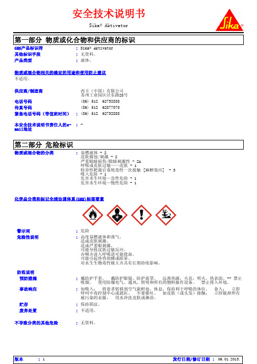
Sika Aktivator Chinese (2)
最重要的急性和延迟症状/效应
潜在的急性健康影响
眼睛接触
: 造成严重眼刺激。
吸入
: 可抑制中枢神经系统 (CNS)。 可能引起昏昏欲睡或眩晕。 接触分解产物下会导致 健康危险。 暴露后,严重的影响会延迟才出现。
皮肤接触
: 造成皮肤刺激。 可能导致皮肤过敏反应。
食入
: 可抑制中枢神经系统 (CNS)。 吞咽并进入呼吸道可能致命。 刺激口腔、咽喉和 胃。
安全技术说明书
Sika® Aktivator
第一部分 物质或化合物和供应商的标识
GHS产品标识符 其他标识手段 产品类型
: Sika® Aktivator : 无资料。 : 液体。
物质或混合物相关的确定的用途和使用防止建议 不适用。
供应商/制造商
电话号码 传真号码 紧急电话号码(带值班时间)
西卡(中国)有限公司 苏州工业园区泾东路28号
: 33123-1
组分名称
%
CAS号码
石油加氢轻石脑油 庚烷 三(十二烷基苯磺酸基-O)(2-丙氧基)合钛 N-[3-(三甲氧基硅基)丙基]-1,2-乙二胺
>= 50 - < 75 >= 25 - < 35 >= 1 - < 3 >= 1 - < 2.5
64742-49-0 142-82-5 61417-55-8 1760-24-3
: 若风险评估结果表明是必要的,在接触化学产品时,请始终配带符合标准的抗化学腐 蚀,不渗透的手套。
: 个人防护用品的选择应以执行工作种类和所冒风险为根据,并且须得到专业人员的核 准。
版本
:1
发行日期/修订日期 : 06.01.2013.
Sika® Aktivator
泰勒螺柱焊接系统 SIK2-H电容放电式 全自动螺柱焊枪 操作说明书
泰勒螺柱焊接系统有限公司SIK2-H电容放电式全自动螺柱焊枪操作说明书GUIDE VERSION 2L目录页码内容3 总则5 简介6 总体布局7 焊接步骤8 安全11 焊枪分解图及零部件列表 22 设备调节24 焊接速度25 跟换螺柱直径27 更换夹头28 夹头类型30 螺柱进料软管31 更换推杆32 推杆类型32 顶端传感器33 焊接质量34 故障诊断38 EC合格证制造厂家英国泰勒螺柱焊接系统有限公司地址:COMMERCIAL ROADDEWSBURYWEST YORKSHIREWF13 2BDENGLAND电话: +44 (0)1924 452123传真: +44 (0)1924 430059邮箱: ***************************技术支持电话: +44 (0)1924 487703销售电话: +44 (0)1924 487701说明书用途本说明书适用于 :☞焊接系统设备操作用.☞本焊接系统终端客户安装、操作人员用。
本说明书提供以下技术指导 :☞安装及联接☞系统操作☞技术参数☞零部件☞附件更详尽信息如需更详尽资料请直接联系我们(详见第1页)或致电当地技术支持(可致电我司查询分销商及代理商联系方式)本说明书包含一些重要信息,是操作者安全使用本焊接系统的必备品。
系统操作人员必须要完全掌握本说明书的使用方法。
为安全起见,本说明书应放置于操作人员随时可取之处。
系统销售或转让时必须随机配备本说明书,并请立即告知我司购机者地址、姓名以便我司能及时联系确保设备安全。
系统安装前请仔细阅读本说明书。
请严格遵守安全操作指导。
简介设备说明电容放电式螺柱焊接设备结构轻盈、便于携带,特别适合于较小直径的螺柱焊接,可将碳钢及不锈钢螺柱在较薄的金属板、抛光或预涂材料的工件上进行焊接,绝大多数情况下几乎不留焊接痕迹。
该设备由一台控制电源,一把全自动焊枪,以及一些必备的焊接电缆组成。
工艺电容放电式螺柱焊接是一种利用电容放电产生的能量进行焊接的一种焊接工艺。
Sika Grout 214产品说明
Sika Grout® 214水泥基无收缩自流平灌浆材料简介Sika Grout®214为无收缩、自流平、高性能的预拌型水泥基灌浆材料。
可操作时间长,适合在不同环境温度下使用。
使用Sika Grout 214 可在如下场合作为灌浆料使用:z设备基础z预制装配式柱的施工z锚杆在混凝土中的固定z桥梁承台支座z洞穴,裂缝, 凹洼处等z任何需要填充但施工受限制的地方优点Sika Grout 214是易用(只需加水),且具有下列优点的材料:z符合GB/T50448-2008(ll类),JC/T986-2005,YB/T9261-98(ll级)z搅拌,施工简单z优异的流动性能z收缩补偿z强度增长快z最终强度高z抗冲击,耐振动z无毒,无腐蚀性z不含铁质和氯离子技术数据外观灰色粉状粉料堆积密度~1.5kg/ l湿时比重 2.13-2.2kg/l储存期自生产之日起,在阴凉,干燥环境下原封保存,9个月包装 25kg袋装特性以下数据基于3.75L水25kg粉料的配比:流动度满足《水泥基灌浆材料应用技术规范》GB/T 50448-2008的要求。
初始值:≥340mm,30分钟保留值:≥310mm。
抗压强度满足《水泥基灌浆材料》JC/T 986-2005的要求。
龄期1天3天7天 28天抗压强度(Mpa)≥25≥40≥50≥80表面处理混凝土表面须干净,坚实,无油脂,油污,无水泥浮浆以及无附着不牢的小颗粒。
金属(铁和钢材)表面必须无氧化皮,铁锈以及油脂、油污。
所有吸水性基面必须用干净水使之充分浸润饱和,但在Sikagrout 214施工前应做到基表无明水和小水坑。
混合每一包(25kg粉料)建议加水量为3.6-3.9L先把70-80%预先称重好的干净水加入到一干净容器中,然后在不断搅拌的同时慢慢加入整包的Sika grout 214。
然后再加入剩余的水并继续低速(最大800rpm)搅拌2-4分钟,直到混合均匀。
西卡214金属灌浆料说明
wTel: +86 20 82266066Fax: +86 20 82266022Page: 1 / 21.1Chemical Character: modified epoxy resin on bisphenol A.1.2Form: liquid.1.3Color: colorless1.4Odor: slight2PHYSICAL AND SAFETY DATA (Not technical specifications. Unless specified tested at 20℃. All temps quoted in ℃)2.1Changes in Physical state:2.2Density (20℃) Kg/L: 1.13 g/ml Bulk density (kg/m3 ): kg / m32.3Vapor pressure:2.4Viscosity(23℃): 550±60 mPa.s,2.5Water solubility: insoluble2.6PH Value: 62.7Flash point:2.8Ignition Temp.:2.9Explosion limits: N/A2.10Thermal decomp.: :>170℃2.11Hazardous decomposition products:2.12Hazardous reaction:2.13Further information:3TRANSPORTIMDG: UN No.: ICAO/IATA: Tremcard No.:GGVE/GGVS: RID/ADR: ADNR:Other information:4.REGULATIONS5PROTECTIVE MEASURES, STORAGE AND HANDLING5.1Technical protective measures:DO NOT TRANSFER INTO UNLABELED CONTAINERS.5.2Personal: Respiratory protection: Not applicableEye protection: Tightly fitting protecting goggles.Hand protection: Gloves, e.g. rubber.Other:5.3Industrial hygiene: EXPERTS ALWAYS WEAR THE RIGHT PROTECTIVE CLOTHING.Observe good house keeping and general hygiene guidelines.5.4Protection against fire and explosion: N / A5.5Disposal: Product: must be disposed of in a special waste disposal unit in accordance with the corresponding regulationPackaging: completely emptied packagings can be given for recycling. Packaging that cannot be cleaned shouldbe disposed of as product waste.6MEASURES IN CASE OF ACCIDENTS AND FIRES6.1After spillage: All chemical spillages must be dealt with as soon as possible to prevent contamination. Damage or stainingof the area affected (especially with liquid products). Attention is drawn to the Control of Pollution Act 1974, the provisionThe information in this safety data sheet respects the actual status of knowledge at the date of publication. They do not imply any warranty. For warranty obligations the specific product descriptions and General Status Conditions are of relativance only.of which is enforced by local authorities. Sweep up spillages. Place in polyethene bags for disposal to an authorized waste site. Wash the area with strong industrial detergent and hot water.6.2 Extinguishing media suitable: compatible with all usual extinguishing media.Not be used: N/A6.3 First aidIngestion : Do not induce vomiting. Summon a doctor immediately.Eye contact : Rinse immediately with opened eyelids under running water for 15 minutes and summon a doctorimmediately.Skin contact : Remove contaminated clothing. Wash off immediately with soap and water. Consult a doctor if skinirritation persists.Inhalation : Remove to fresh air. Give oxygen if required. In the event of symptoms take medical treatment.6.4 Further information : Sika Limited products are generally safe to use provided certain precautions normally taken whenhandling chemicals are observed. Unless specified products should not come into contact with drinking water, foodstuffs or food equipment and measures should be taken to prevent skin contact, since people with particularly sensitive skin may be affected. The use of barrier creams, goggles and industrial gloves are recommended. The skin should be cleansed at the end of each working period using a suitable industrial cleanser or warm water and soap, the use of solvents to clean the skin is not recommended. Adequate ventilation of the working area is recommended. Take careful note of all safety information on data sheets and labels.7 INFORMATION ON TOXICITYContact with eyes, skin and mucous membranes may cause slight irritation. Sensitization and allergic reaction may occur.8 INFORMATION ON ECOLOGICAL EFFECTSAddition informationDo not allow to enter waste water drain, waterways or soil.9 FURTHER INFORMATIONAll statements are based on our experience to date. Form based on DIN 52900.The information contained in this Safety Data Sheet corresponds to our level of knowledge at the time of publication. Allwarranties are excluded. Our most current General Sales Conditions shall apply. Please consult the Technical Data Sheet prior to any use and processing.SAFETY DATA SHEET Sikadur 42HE, Part A01/2007Sika Ltd., China No.96,JunDa Road, Eastern Section, GET Guangzhou, China, post code: 510530 Tel: +86 20 82266066 Fax: +86 20 82266022 Pages: 2/2。
维吉斯达空气能说明书

维吉斯达空气能说明书空气能热泵手动开关设定:当水温达到设定供水温度要求时(出厂设置为40度),按“供水”键即可供水。
菜单功能选择:“功能”键,可进行时钟、定时开、关主机、定时开、关供水泵、确定回水(供水)温度、光度要求、除霜参数要求、电加热温度要求七项菜单功能选择。
要进行功能选择时,必须在开机状态下将“功能”键长按5秒才能进入功能选择,确定选取功能完成后,不再操作控制板时,10秒钟后自动退出功能选择。
1)时钟功能设定:A。
长按“功能”健,进入功能选择后,再按一下“功能”键,再按“确认键”进入时间设定功能,此时显示屏时钟显示闪动,可对小时参数进行调整,按参数“▲▼”键,小时数字可上下调整。
B。
完成小时设置后,按“确认”键,进入分钟数设置,按参数“▲、▼”键,分钟数可上下调整。
再按“确认”键,时钟设定完成。
2)主机定时设定:1、。
进入功能选择后,按二下“功能”键,显示屏“主机”菜单闪动,按“确认”键后进入主机定时功能。
2、时段选择或定时开关查询,主机定时可选择3个时段,进入主机定时功能时,按“时段”键可对定时时段进行选择。
当时段定时完成后,可按“时段”键对定时时段进行查询。
其中一项定时开、关有效时,显示屏定时开、关亮。
3、定时开、关设定,按一下“时段”键,水温显示区显示“01”,再按一下“定时”键,定时开闪动,同时时钟区闪动,按参数“▲、▼”键,可调整定时时间,如再按一下“定时”键,取消定时,此时定时开消失,(设定精度为时间区为1小时,分钟区为1分钟),再按“确认”键,定时开设定完成。
接着再按“时段”键,水温显示“02”,再按一下“定时”键,定时关闪动,同时时钟区闪动,按参数“▲、▼”键,可调整定时时间。
再依次按“时段”键和“定时”键,依次设置第二、第三时段按以上的第一时段操作来设定(注:定时时间以面板时钟时间为准、主机定时开关机设置多时段时:时断区域不能互相跨越、冲突、否则设定无效) 3)定时供水设定:进入功能选择后,按三下“功能”键,显示屏“供水”菜单闪动,按“确认”键后进入定时供水功能。
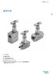
世伟洛克 GU系列 通用针阀 说明书
通用针阀 A-335A通用针阀GU 系列■ 直通型和角型■ 不锈钢和碳钢阀体材料■ 压力达到 6000 psig (413 bar)■ 使用 PTFE 填料时、温度可高达 232°C (450°F); 使用石墨填料时、温度可高达343°C (650°F)A-336 针形阀和计量阀A通用针阀 A-337A压力—温度额定值结构材料➀ 带焊接端接的阀体采用防锈涂层而不是镀锌。
流量数据测试所有世伟洛克 (Swagelok) GU 系列针阀都在工厂内使用 1000 psig (69 bar) 氮气进行过测试。
阀座的最大容许泄漏率为 0.1 std cm 3/分钟。
壳体测试时使用检漏液、达到未检测到泄漏的要求。
清洁和包装所有世伟洛克 GU 系列针阀都是按照世伟洛克标准清洁和包装规范 (SC-10)、MS-06-62 进行清洁和包装的。
角型旋转打开圈数流量系数 (C v )流量系数 (C v )直通型开启圈数与流量系数的关系曲线A-338 针形阀和计量阀A 订购信息与尺寸尺寸仅供参考、可能有变动。
直通型角型角型通用针阀 A-339A订购信息与尺寸尺寸仅供参考、可能有变动。
直通型A-340 针形阀和计量阀A 选购件欲订购带多个选购件的阀门、请按字母顺序添加相应代号。
高温阀杆填料、阀帽密封可提供石墨阀杆填料和阀帽密封材料来获得高达 343°C (650°F)的工作温度。
欲订购采用石墨材料的阀门、请在阀订购号中添加‑G。
示例: SS-4GUF4‑G防擅动手柄防擅动手柄降低了发生人为错误或故意改动的风险。
可以使用单独销售的防擅动钥匙操作这种阀门。
欲订购采用防擅动手柄的阀门、请在阀订购号中添加‑AT。
示例: SS-4GUF4‑AT圆形带锁手柄带锁手柄可以把阀门锁在任何位置。
4GU和 8GU 系列阀门的这种圆形手柄适合0.22 in. (5.7 mm) 以下的钩环直径、16GU系列阀门适合 0.28 in. (7.0 mm)以下的钩环直径。
- 1、下载文档前请自行甄别文档内容的完整性,平台不提供额外的编辑、内容补充、找答案等附加服务。
- 2、"仅部分预览"的文档,不可在线预览部分如存在完整性等问题,可反馈申请退款(可完整预览的文档不适用该条件!)。
- 3、如文档侵犯您的权益,请联系客服反馈,我们会尽快为您处理(人工客服工作时间:9:00-18:30)。
Sika Grout® 214
水泥基无收缩自流平灌浆材料
简介Sika Grout®214为无收缩、自流平、高性能的预拌型水泥基灌浆材料。
可操作时间长,适合在不同环境温度下使用。
使用Sika Grout 214 可在如下场合作为灌浆料使用:
z设备基础
z预制装配式柱的施工
z锚杆在混凝土中的固定
z桥梁承台支座
z洞穴,裂缝, 凹洼处等
z任何需要填充但施工受限制的地方
优点Sika Grout 214是易用(只需加水),且具有下列优点的材料:z符合GB/T50448-2008(ll类),JC/T986-2005,YB/T9261-98
(ll级)
z搅拌,施工简单
z优异的流动性能
z收缩补偿
z强度增长快
z最终强度高
z抗冲击,耐振动
z无毒,无腐蚀性
z不含铁质和氯离子
技术数据
外观灰色粉状
粉料堆积密度~1.5kg/ l
湿时比重 2.13-2.2kg/l
储存期自生产之日起,在阴凉,干燥环境下原封保存,9个月
包装 25kg袋装
特性以下数据基于3.75L水25kg粉料的配比:
流动度满足《水泥基灌浆材料应用技术规范》GB/T 50448-2008的
要求。
初始值:≥340mm,30分钟保留值:≥310mm。
抗压强度满足《水泥基灌浆材料》JC/T 986-2005的要求。
龄期1天3天7天 28天
抗压强度(Mpa)≥25≥40≥50≥80
表面处理混凝土表面须干净,坚实,无油脂,油污,无水泥浮浆以及无附
着不牢的小颗粒。
金属(铁和钢材)表面必须无氧化皮,铁锈以及
油脂、油污。
所有吸水性基面必须用干净水使之充分浸润饱和,但在Sika
grout 214施工前应做到基表无明水和小水坑。
混合每一包(25kg粉料)建议加水量为3.6-3.9L
先把70-80%预先称重好的干净水加入到一干净容器中,然后在
不断搅拌的同时慢慢加入整包的Sika grout 214。
然后再加入剩
余的水并继续低速(最大800rpm)搅拌2-4分钟,直到混合均
匀。
停止搅拌,保持现状1-2分钟,然后再继续低速搅拌1-2分
钟。
施工立即将搅拌好的料进行灌注,确保灌注过程中空气能够通畅排
出。
进行设备基础灌浆时,需确保提供足够的压力以维持灌浆料持续
地流动。
砂浆表面暴露在外的面积越少越好。
大面积和/或大体积灌浆时,需将不含泥的骨料加入到Sika grout
214中以降低固化过程中产生的热量。
加入骨料的重量不能超过
Sika grout 214的重量。
如有疑问,请与我们联系。
施工温度最低50C,最高350C
养护用Antisol E 或其它合适的方法养护暴露在外面的表面
清洁工具使用后应立即用水进行清洗,固化后的砂浆只能用机械方法
来去除。
要点Sika grout 214只能用于灌浆。
最小灌注厚度为10mm.
材料用量(kg)Sika grout 214 1.88kg 25kg 75.5*25kg
水0.283L 3.75L 283L
1m3 砂浆体积1L 13.25L
补充要点
设备基础灌浆
湿润基面到饱和但表面无明水。
维持足够的压力以使灌浆持续地
流动。
用钢丝或链条搅动灌浆料,以确保所有的空隙都被填满,并且内
部的空气能够被自由排出。
地脚螺栓锚固彻底润湿基面,螺栓孔内无积水。
尽可能地将锚孔灌满,注意灌浆料应被连续注入。
螺栓与孔壁的间距应至少大于灌浆料中最大
骨料料径的3倍。
(最小间距10mm)
大体积灌浆根据其体积,可选用较大的石子,如:4~8mm或8~16mm或16~32mm,加入到灌浆料中,石子加入量不超过50%~100%灌
浆材料的重量,卵石比碎石好。
若需要,加以轻微地振动可使其
具有更好的密实度。
数据来源本产品说明书所有技术数据均基于实验室测试结果。
由于实际环境超出了我们的控制,现场测得的数据可能会有所不同。
地方限制请注意:为满足当地法律法规的具体要求,该产品的性能可能因地而异。
请参考当地产品说明书以获得应用方面的准确描述。
健康与安全为了得到有关安全操作,储存和处理化学品的信息和建议,用户应参阅包含物理、生态、毒性和其它安全相关数据的最新材料安
全数据表。
