哈里伯顿旋转导向GP Brief Introduction for Rig Crew_V02
哈里伯顿旋转导向仪器在JY1X6-1HF井的应用
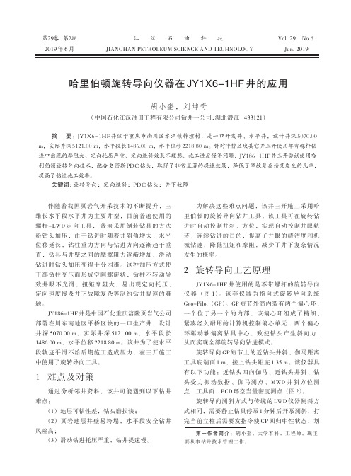
靠,否则管线抖动伤人。
3 现场应用
(1) 钻具组合及钻进参数 旋转导向钻具组合:Φ215.9 mmPDC 钻头+旋 转导向 GP 短节+测斜短节+伽马短节+PWD 短节+脉 冲短节+滤网短节+浮阀 +Φ127 mm 加重钻杆×6 根+Φ165 mm 随钻震击器+Φ127 mm 加重钻杆×6 根+Φ127 mm 钻杆×360 根+Φ127 mm 加重钻杆× 18 根+Φ127 mm 钻杆。 钻进参数:钻压 120~140 kN,钻速 100~110 rpm,排量 30 L/s,泵压 22 MPa。
摘 要 :JY1X6-1HF 井位于重庆市南川区水江镇梓潼村,是一口开发井、水平井,设计井深 5070.00 m,实际井深5121.00 m,水平段长1486.00 m,水平位移2218.80 m。针对平桥区块其它井三开使用单弯螺杆钻 进中出现的摩阻大、定向托压严重、定向造斜效果不理想、施工进度慢等问题,JY186-1HF 井三开尝试使用哈 利伯顿旋转导向技术,配合史密斯 PDC 钻头,取得了非常显著的提速效果,降低了事故复杂情况发生的几率, 提高了钻进施工效率。
1 难点及对策
通过分析邻井资料,该井可能遇到以下钻井 难点:
(1) 地层可钻性差,钻头磨损快; (2) 页 岩 地 层 井 壁 易 垮 塌 , 水 平 段 安 全 钻 井 风险高; (3) 滑动钻进托压严重,钻井提速慢。
为解决这些难点问题,该井三开施工采用哈 里伯顿的旋转导向钻井工具,该工具可在旋转钻 进时自动控制井斜、方位,实现自动控制井眼轨 迹、连续钻进的目的,提高了井眼的清洁度和机 械钻速,降低扭矩和摩阻,减少了井下复杂情况 发生的概率。
斯仑贝谢所有测井曲线英文名称

斯仑贝谢所有测井曲线英文名称OCEAN DRILLING PROGRAMACRONYMS USED FOR WIRELINE SCHLUMBERGER TOOLS ACT Aluminum Clay ToolAMS Auxiliary Measurement SondeAPS Accelerator Porosity SondeARI Azimuthal Resistivity ImagerASI Array Sonic ImagerBGKT Vertical Seismic Profile ToolBHC Borehole Compensated Sonic ToolBHTV Borehole TeleviewerCBL Casing Bond LogCNT Compensated Neutron ToolDIT Dual Induction ToolDLL Dual LaterologDSI Dipole Sonic ImagerFMS Formation MicroScannerGHMT Geologic High Resolution Magnetic Tool GPIT General Purpose Inclinometer ToolGR Natural Gamma RayGST Induced Gamma Ray Spectrometry Tool HLDS Hostile Environment Lithodensity Sonde HLDT Hostile Environment Lithodensity Tool HNGS Hostile Environment Gamma Ray SondeLDT Lithodensity ToolLSS Long Spacing Sonic ToolMCD Mechanical Caliper DeviceNGT Natural Gamma Ray Spectrometry Tool NMRT Nuclear Resonance Magnetic ToolQSST Inline Checkshot ToolSDT Digital Sonic ToolSGT Scintillation Gamma Ray ToolSUMT Susceptibility Magnetic ToolUBI Ultrasonic Borehole ImagerVSI Vertical Seismic ImagerWST Well Seismic ToolWST-3 3-Components Well Seismic ToolOCEAN DRILLING PROGRAMACRONYMS USED FOR LWD SCHLUMBERGER TOOLSADN Azimuthal Density-NeutronCDN Compensated Density-NeutronCDR Compensated Dual ResistivityISONIC Ideal Sonic-While-DrillingNMR Nuclear Magnetic ResonanceRAB Resistivity-at-the-BitOCEAN DRILLING PROGRAMACRONYMS USED FOR NON-SCHLUMBERGER SPECIALTY TOOLS MCS Multichannel Sonic ToolMGT Multisensor Gamma ToolSST Shear Sonic ToolTAP Temperature-Acceleration-Pressure ToolTLT Temperature Logging ToolOCEAN DRILLING PROGRAMACRONYMS AND UNITS USED FOR WIRELINE SCHLUMBERGER LOGS AFEC APS Far Detector Counts (cps)ANEC APS Near Detector Counts (cps)AX Acceleration X Axis (ft/s2)AY Acceleration Y Axis (ft/s2)AZ Acceleration Z Axis (ft/s2)AZIM Constant Azimuth for Deviation Correction (deg)APLC APS Near/Array Limestone Porosity Corrected (%)C1 FMS Caliper 1 (in)C2 FMS Caliper 2 (in)CALI Caliper (in)CFEC Corrected Far Epithermal Counts (cps)CFTC Corrected Far Thermal Counts (cps)CGR Computed (Th+K) Gamma Ray (API units)CHR2 Peak Coherence, Receiver Array, Upper DipoleCHRP Compressional Peak Coherence, Receiver Array, P&SCHRS Shear Peak Coherence, Receiver Array, P&SCHTP Compressional Peak Coherence, Transmitter Array, P&SCHTS Shear Peak Coherence, Transmitter Array, P&SCNEC Corrected Near Epithermal Counts (cps)CNTC Corrected Near Thermal Counts (cps)CS Cable Speed (m/hr)CVEL Compressional Velocity (km/s)DATN Discriminated Attenuation (db/m)DBI Discriminated Bond IndexDEVI Hole Deviation (degrees)DF Drilling Force (lbf)DIFF Difference Between MEAN and MEDIAN in Delta-Time Proc. (microsec/ft) DRH HLDS Bulk Density Correction (g/cm3)DRHO Bulk Density Correction (g/cm3)DT Short Spacing Delta-Time (10'-8' spacing; microsec/ft)DT1 Delta-Time Shear, Lower Dipole (microsec/ft)DT2 Delta-Time Shear, Upper Dipole (microsec/ft)DT4P Delta- Time Compressional, P&S (microsec/ft)DT4S Delta- Time Shear, P&S (microsec/ft))DT1R Delta- Time Shear, Receiver Array, Lower Dipole (microsec/ft)DT2R Delta- Time Shear, Receiver Array, Upper Dipole (microsec/ft) DT1T Delta-Time Shear, Transmitter Array, Lower Dipole (microsec/ft) DT2T Delta-Time Shear, Transmitter Array, Upper Dipole (microsec/ft) DTCO Delta- Time Compressional (microsec/ft)DTL Long Spacing Delta-Time (12'-10' spacing; microsec/ft)DTLF Long Spacing Delta-Time (12'-10' spacing; microsec/ft)DTLN Short Spacing Delta-Time (10'-8' spacing; microsec/ftDTRP Delta-Time Compressional, Receiver Array, P&S (microsec/ft) DTRS Delta-Time Shear, Receiver Array, P&S (microsec/ft)DTSM Delta-Time Shear (microsec/ft)DTST Delta-Time Stoneley (microsec/ft)DTTP Delta-Time Compressional, Transmitter Array, P&S (microsec/ft) DTTS Delta-Time Shear, Transmitter Array, P&S (microsec/ft)ECGR Environmentally Corrected Gamma Ray (API units)EHGR Environmentally Corrected High Resolution Gamma Ray (API units) ENPH Epithermal Neutron Porosity (%)ENRA Epithermal Neutron RatioETIM Elapsed Time (sec)FINC Magnetic Field Inclination (degrees)FNOR Magnetic Field Total Moment (oersted)FX Magnetic Field on X Axis (oersted)FY Magnetic Field on Y Axis (oersted)FZ Magnetic Field on Z Axis (oersted)GR Natural Gamma Ray (API units)HALC High Res. Near/Array Limestone Porosity Corrected (%)HAZI Hole Azimuth (degrees)HBDC High Res. Bulk Density Correction (g/cm3)HBHK HNGS Borehole Potassium (%)HCFT High Resolution Corrected Far Thermal Counts (cps)HCGR HNGS Computed Gamma Ray (API units)HCNT High Resolution Corrected Near Thermal Counts (cps)HDEB High Res. Enhanced Bulk Density (g/cm3)HDRH High Resolution Density Correction (g/cm3)HFEC High Res. Far Detector Counts (cps)HFK HNGS Formation Potassium (%)HFLC High Res. Near/Far Limestone Porosity Corrected (%)HEGR Environmentally Corrected High Resolution Natural Gamma Ray (API units) HGR High Resolution Natural Gamma Ray (API units)HLCA High Res. Caliper (inHLEF High Res. Long-spaced Photoelectric Effect (barns/e-)HNEC High Res. Near Detector Counts (cps)HNPO High Resolution Enhanced Thermal Nutron Porosity (%)HNRH High Resolution Bulk Density (g/cm3)HPEF High Resolution Photoelectric Effect (barns/e-)HRHO High Resolution Bulk Density (g/cm3)HROM High Res. Corrected Bulk Density (g/cm3)HSGR HNGS Standard (total) Gamma Ray (API units)HSIG High Res. Formation Capture Cross Section (capture units)HSTO High Res. Computed Standoff (in)HTHO HNGS Thorium (ppm)HTNP High Resolution Thermal Neutron Porosity (%)HURA HNGS Uranium (ppm)IDPH Phasor Deep Induction (ohmm)IIR Iron Indicator Ratio [CFE/(CCA+CSI)]ILD Deep Resistivity (ohmm)ILM Medium Resistivity (ohmm)IMPH Phasor Medium Induction (ohmm)ITT Integrated Transit Time (s)LCAL HLDS Caliper (in)LIR Lithology Indicator Ratio [CSI/(CCA+CSI)]LLD Laterolog Deep (ohmm)LLS Laterolog Shallow (ohmm)LTT1 Transit Time (10'; microsec)LTT2 Transit Time (8'; microsec)LTT3 Transit Time (12'; microsec)LTT4 Transit Time (10'; microsec)MAGB Earth's Magnetic Field (nTes)MAGC Earth Conductivity (ppm)MAGS Magnetic Susceptibility (ppm)MEDIAN Median Delta-T Recomputed (microsec/ft) MEAN Mean Delta-T Recomputed (microsec/ft) NATN Near Pseudo-Attenuation (db/m)NMST Magnetometer Temperature (degC)NMSV Magnetometer Signal Level (V)NPHI Neutron Porosity (%)NRHB LDS Bulk Density (g/cm3)P1AZ Pad 1 Azimuth (degrees)PEF Photoelectric Effect (barns/e-)PEFL LDS Long-spaced Photoelectric Effect (barns/e-)PIR Porosity Indicator Ratio [CHY/(CCA+CSI)]POTA Potassium (%)RB Pad 1 Relative Bearing (degrees)RHL LDS Long-spaced Bulk Density (g/cm3)RHOB Bulk Density (g/cm3)RHOM HLDS Corrected Bulk Density (g/cm3)RMGS Low Resolution Susceptibility (ppm)SFLU Spherically Focused Log (ohmm)SGR Total Gamma Ray (API units)SIGF APS Formation Capture Cross Section (capture units) SP Spontaneous Potential (mV)STOF APS Computed Standoff (in)SURT Receiver Coil Temperature (degC)SVEL Shear Velocity (km/s)SXRT NMRS differential Temperature (degC)TENS Tension (lb)THOR Thorium (ppm)TNRA Thermal Neutron RatioTT1 Transit Time (10' spacing; microsec)TT2 Transit Time (8' spacing; microsec)TT3 Transit Time (12' spacing; microsec)TT4 Transit Time (10' spacing; microsec)URAN Uranium (ppm)V4P Compressional Velocity, from DT4P (P&S; km/s)V4S Shear Velocity, from DT4S (P&S; km/s)VELP Compressional Velocity (processed from waveforms; km/s)VELS Shear Velocity (processed from waveforms; km/s)VP1 Compressional Velocity, from DT, DTLN, or MEAN (km/s)VP2 Compressional Velocity, from DTL, DTLF, or MEDIAN (km/s)VCO Compressional Velocity, from DTCO (km/s)VS Shear Velocity, from DTSM (km/s)VST Stonely Velocity, from DTST km/s)VS1 Shear Velocity, from DT1 (Lower Dipole; km/s)VS2 Shear Velocity, from DT2 (Upper Dipole; km/s)VRP Compressional Velocity, from DTRP (Receiver Array, P&S; km/s)VRS Shear Velocity, from DTRS (Receiver Array, P&S; km/s)VS1R Shear Velocity, from DT1R (Receiver Array, Lower Dipole; km/s) VS2R Shear Velocity, from DT2R (Receiver Array, Upper Dipole; km/s) VS1T Shear Velocity, from DT1T (Transmitter Array, Lower Dipole; km/s) VS2T Shear Velocity, from DT2T (Transmitter Array, Upper Dipole; km/s) VTP Compressional Velocity, from DTTP (Transmitter Array, P&S; km/s)VTS Shear Velocity, from DTTS (Transmitter Array, P&S; km/s)#POINTS Number of Transmitter-Receiver Pairs Used in Sonic Processing W1NG NGT Window 1 counts (cps)W2NG NGT Window 2 counts (cps)W3NG NGT Window 3 counts (cps)W4NG NGT Window 4 counts (cps)W5NG NGT Window 5 counts (cps)OCEAN DRILLING PROGRAMACRONYMS AND UNITS USED FOR LWD SCHLUMBERGER LOGSAT1F Attenuation Resistivity (1 ft resolution; ohmm)AT2F Attenuation Resistivity (2 ft resolution; ohmm)AT3F Attenuation Resistivity (3 ft resolution; ohmm)AT4F Attenuation Resistivity (4 ft resolution; ohmm)AT5F Attenuation Resistivity (5 ft resolution; ohmm)ATR Attenuation Resistivity (deep; ohmm)BFV Bound Fluid Volume (%)B1TM RAB Shallow Resistivity Time after Bit (s)B2TM RAB Medium Resistivity Time after Bit (s)B3TM RAB Deep Resistivity Time after Bit (s)BDAV Deep Resistivity Average (ohmm)BMAV Medium Resistivity Average (ohmm)BSAV Shallow Resistivity Average (ohmm)CGR Computed (Th+K) Gamma Ray (API units)DCAL Differential Caliper (in)DROR Correction for CDN rotational density (g/cm3).DRRT Correction for ADN rotational density (g/cm3).DTAB AND or CDN Density Time after Bit (hr)FFV Free Fluid Volume (%)GR Gamma Ray (API Units)GR7 Sum Gamma Ray Windows GRW7+GRW8+GRW9-Equivalent to Wireline NGT window 5 (cps) GRW3 Gamma Ray Window 3 counts (cps)-Equivalent to Wireline NGT window 1GRW4 Gamma Ray Window 4 counts (cps)-Equivalent to Wireline NGT window 2GRW5 Gamma Ray Window 5 counts (cps)-Equivalent to Wireline NGT window 3 GRW6 Gamma Ray Window 6 counts (cps)-Equivalent to Wireline NGT window 4 GRW7 Gamma Ray Window 7 counts (cps)GRW8 Gamma Ray Window 8 counts (cps)GRW9 Gamma Ray Window 9 counts (cps)GTIM CDR Gamma Ray Time after Bit (s)GRTK RAB Gamma Ray Time after Bit (s)HEF1 Far He Bank 1 counts (cps)HEF2 Far He Bank 2 counts (cps)HEF3 Far He Bank 3 counts (cps)HEF4 Far He Bank 4 counts (cps)HEN1 Near He Bank 1 counts (cps)HEN2 Near He Bank 2 counts (cps)HEN3 Near He Bank 3 counts (cps)HEN4 Near He Bank 4 counts (cps)MRP Magnetic Resonance PorosityNTAB ADN or CDN Neutron Time after Bit (hr)PEF Photoelectric Effect (barns/e-)POTA Potassium (%) ROPE Rate of Penetration (ft/hr)PS1F Phase Shift Resistivity (1 ft resolution; ohmm)PS2F Phase Shift Resistivity (2 ft resolution; ohmm)PS3F Phase Shift Resistivity (3 ft resolution; ohmm)PS4F Phase Shift Resistivity (4 ft resolution; ohmm)PS5F Phase Shift Resistivity (5 ft resolution; ohmm)PSR Phase Shift Resistivity (shallow; ohmm)RBIT Bit Resistivity (ohmm)RBTM RAB Resistivity Time After Bit (s)RING Ring Resistivity (ohmm)ROMT Max. Density Total (g/cm3) from rotational processing ROP Rate of Penetration (m/hr)ROP1 Rate of Penetration, average over last 1 ft (m/hr). ROP5 Rate of Penetration, average over last 5 ft (m/hr) ROPE Rate of Penetration, averaged over last 5 ft (ft/hr) RPM RAB Tool Rotation Speed (rpm)RTIM CDR or RAB Resistivity Time after Bit (hr)SGR Total Gamma Ray (API units)T2 T2 Distribution (%)T2LM T2 Logarithmic Mean (ms)THOR Thorium (ppm)TNPH Thermal Neutron Porosity (%)TNRA Thermal RatioURAN Uranium (ppm)OCEAN DRILLING PROGRAMADDITIONAL ACRONYMS AND UNITS(PROCESSED LOGS FROM GEOCHEMICAL TOOL STRING)AL2O3 Computed Al2O3 (dry weight %)AL2O3MIN Computed Al2O3 Standard Deviation (dry weight %) AL2O3MAX Computed Al2O3 Standard Deviation (dry weight %) CAO Computed CaO (dry weight %)CAOMIN Computed CaO Standard Deviation (dry weight %) CAOMAX Computed CaO Standard Deviation (dry weight %) CACO3 Computed CaCO3 (dry weight %)CACO3MIN Computed CaCO3 Standard Deviation (dry weight %) CACO3MAX Computed CaCO3 Standard Deviation (dry weight %) CCA Calcium Yield (decimal fraction)CCHL Chlorine Yield (decimal fraction)CFE Iron Yield (decimal fraction)CGD Gadolinium Yield (decimal fraction)CHY Hydrogen Yield (decimal fraction)CK Potassium Yield (decimal fraction)CSI Silicon Yield (decimal fraction)CSIG Capture Cross Section (capture units)CSUL Sulfur Yield (decimal fraction)CTB Background Yield (decimal fraction)CTI Titanium Yield (decimal fraction)FACT Quality Control CurveFEO Computed FeO (dry weight %)FEOMIN Computed FeO Standard Deviation (dry weight %) FEOMAX Computed FeO Standard Deviation (dry weight %) FEO* Computed FeO* (dry weight %)FEO*MIN Computed FeO* Standard Deviation (dry weight %) FEO*MAX Computed FeO* Standard Deviation (dry weight %) FE2O3 Computed Fe2O3 (dry weight %)FE2O3MIN Computed Fe2O3 Standard Deviation (dry weight %)FE2O3MAX Computed Fe2O3 Standard Deviation (dry weight %) GD Computed Gadolinium (dry weight %)GDMIN Computed Gadolinium Standard Deviation (dry weight %) GDMAX Computed Gadolinium Standard Deviation (dry weight %) K2O Computed K2O (dry weight %)K2OMIN Computed K2O Standard Deviation (dry weight %)K2OMAX Computed K2O Standard Deviation (dry weight %)MGO Computed MgO (dry weight %)MGOMIN Computed MgO Standard Deviation (dry weight %) MGOMAX Computed MgO Standard Deviation (dry weight %)S Computed Sulfur (dry weight %)SMIN Computed Sulfur Standard Deviation (dry weight %) SMAX Computed Sulfur Standard Deviation (dry weight %)SIO2 Computed SiO2 (dry weight %)SIO2MIN Computed SiO2 Standard Deviation (dry weight %)SIO2MAX Computed SiO2 Standard Deviation (dry weight %) THORMIN Computed Thorium Standard Deviation (ppm) THORMAX Computed Thorium Standard Deviation (ppm)TIO2 Computed TiO2 (dry weight %)TIO2MIN Computed TiO2 Standard Deviation (dry weight %) TIO2MAX Computed TiO2 Standard Deviation (dry weight %) URANMIN Computed Uranium Standard Deviation (ppm) URANMAX Computed Uranium Standard Deviation (ppm) VARCA Variable CaCO3/CaO calcium carbonate/oxide factor。
国外旋转导向技术的发展及国内现状

国外旋转导向技术的发展及国内现状王植锐;王俊良【摘要】旋转导向技术在国内外得到广泛应用,以斯伦贝谢、贝克-GE、哈里伯顿、威德福为代表的旋转导向系统已经在国外成为了一项常规的定向井、水平井钻井工具.文章以斯伦贝谢旋转导向系统为例,介绍了斯伦贝谢公司的旋转导向系统、典型的应用实例以及最新现状及他们的研发机制,同时简略介绍了国内旋转导向系统的应用现状.文章认为,国外旋转导向系统已经研制出了具有不同造斜能力、满足不同地质需求的旋转导向系统序列,系统的可靠性高、使用时间长、性能稳定、适用性好.国内的旋转导向系统已经在技术上有突破,在一些井上进行了现场试验,取得了初步的成效,但还需要进行持续不断的科技攻关,以期尽快大规模推广应用.【期刊名称】《钻采工艺》【年(卷),期】2018(041)002【总页数】5页(P37-41)【关键词】旋转导向系统;斯伦贝谢;推靠式;指向式;混合式;造斜能力;钻井系统【作者】王植锐;王俊良【作者单位】重庆科技学院;斯伦贝谢公司沙特阿拉伯达兰基地【正文语种】中文国外从20世纪80年代末期开始进行旋转导向钻井系统的研发,20世纪90年代进入商业化使用,并逐渐改进、升级、完善。
目前,以斯伦贝谢、贝克GE、哈里伯顿、威德福为代表的石油技术服务公司分别拥有自己先进的旋转导向系统序列,大规模应用在油田技术服务中,已经成为了一种主要的定向井、水平井钻井工具。
国内一些研究机构和技术服务公司也在同期开始了自主研发,取得了一些技术上的突破,但与国外服务公司水平相比,还存在着较大的差距。
通过调研,尚未发现有文章全面系统介绍国外旋转导向系统。
斯伦贝谢公司的旋转导向系统占据了大部分的服务市场,具有一定的代表性,因此本文主要以斯伦贝谢公司的旋转导向系统为例介绍国外旋转导向技术的发展现状、研发机制,力争能够有所借鉴,有利于国内旋转导向系统的不断改进、升级、完善,以期尽快大规模地投入商业化应用。
一、斯伦贝谢旋转导向系统介绍1.推靠式旋转导向系统—PowerDrive Orbit斯伦贝谢的推靠式旋转导向系统由最开初的PowerDrive Xtra,升级到PowerDrive X5、PowerDrive X6,目前升级到PowerDrive Orbit。
旋转导向系统和地质导向钻井简介
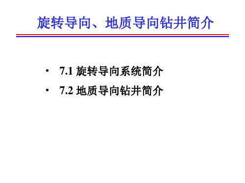
动态推靠式 Power Drive SRD
静态推靠式 Auto Trak RCLS
静态指向式 Geo-pilot
7.1 旋转导向系统简介
三、旋转导向系统的原理
斯伦贝谢公司的PowerDrive系统
7.1 旋转导向系统简介
三、旋转导向系统的原理
哈里伯顿斯派里森公司的Geo-Pilo系统
30' 40' 50' 60' 70' 80' 90' 2000' 年代
滑动导向
7.1 旋转导向系统简介
二、旋转导向钻井的主要优点
• 提高了机械钻速; • 增强了井眼清洁效果; • 增强了井眼轨迹控制精度和
灵活性; • 减少了起下钻次数; • 井眼规则、光滑; • 克服极限位移限制。
7.1 旋转导向系统简介
旋转导向、地质导向钻井简介
• 7.1 旋转导向系统简介 • 7.2 地质导向钻井简介
7.1 旋转导向系统简介
一、导向钻井的发展经过
旋转导向钻井技术是20世纪90年代初期发展起来的 一项钻井新技术,代表了钻井技术发展的最高水平。
LWD
斜 向 器
井 下 马
MWD
弯 外 壳 马
旋 革命性 转 进步
导
达 WLMWD 达 向
7.2 地质导向钻井简介
一、地质导向钻井的仪器系统组成
井下仪器 + 地面系统 + 上位机系地面接口箱
泵冲传感器 计算机
电阻率、伽玛接口箱
打印机
井下仪器串
电阻率短接
脉冲发生器 电子控制短节
电源系统短节 MWD电子测量短节 伽玛测量短节
7.2 地质导向钻井简介
BAKER HUGHS 旋转导向简介

70
Inclination (deg)
60
50
- AutoT rak RCLS - Conventional
40
30
20
10 0.00
1000.00
2000.00
3000.00
4000.00
5000.00
6000.00
Normalized M D (ft)
Auto Trak G3 旋转导向小结
结构紧凑。旋转导向系统总长(包含供电、脉冲发生器,随钻测量、测井系统 和旋转导向系统)不超过16米; 模块化设计。位置可根据实际需要,进行条换; 钻柱振动、冲击、环空压力(ECD),并能实时传输该数据; 具备方位伽玛成像功能,可广泛应用于储层地质导向; 具有旋转导向和近钻头井斜测量功能,在钻具连续旋转的状况下实现井眼轨迹 精确控制; 具有地面与井下仪器指令、命令双向通讯功能,实现地面指令对井下工具姿态 控制; 自动电脑控制下发指令系统;钻进过程中下发指令,不额外占用作业时间; 旋转导向系统具备多种控制模式:导向模式、稳斜模式等;井下闭合环路自动 控制系统; 工具维修简单,在作业现场即可进行旋转导向短节的拆装作业,从而保证现场 作业的顺利进行; 现场配钻具需要2-3小时,快捷、方便。
Thank you
谢谢!
三、 BCPM简介
全系统自动发电 功率:250瓦特;提供33伏直流电 指令发送功能
高速泥浆脉冲数据传输
四、 ONTRAK简介
OnTrak集成传感器模块包括: 定向控制和测量 多相位电磁波传播电阻率 方位伽玛(伽玛成像 ) 环空和钻具内动/ 静压力 监控振动和粘滑振动 存储及数据高速下载Leabharlann 一)定向测量GAMMA LOG
左图井眼进入砂岩薄层 低边首先探测到该地层 (较高边提前5米) 伽玛成像更加真实、显 像化反应地层变化
旋转导向钻井技术及Power-V
旋转导向钻井技术及Power-V导向系统介绍摘要:旋转导向钻井技术主要指井眼轨迹自动控制的闭环自动钻井技术,是20世纪90年代初期发展起来的一项钻井新技术,代表着当今国际钻井技术的最新发展方向,对超深井、超薄油层水平井、大位移井、分支水平井等轨迹控制具有独特效果。
本文分析了旋转导向钻井系统的技术特点,介绍了国内外旋转导向钻井系统的发展、应用情况。
并详细介绍了斯伦贝谢公司旋转导向系统Power-V的组成和工作原理。
1.概述所谓旋转导向钻井,是指钻柱在旋转钻进过程中实现过去只有传统泥浆马达才能实现的准确增斜、稳斜、降斜或者纠方位功能。
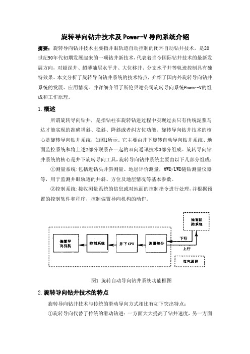
旋转导向钻井技术的核心是旋转导向钻井系统,如图1所示。
它主要由井下旋转自动导向钻井系统、地面监控系统和将上述2部分联系在一起的双向通讯技术3部分组成。
旋转导向钻井系统的核心是井下旋转导向工具,旋转导向钻井系统主要由以下几部分组成:①测量系统:包括近钻头井斜测量、地层评价测量,MWD/LWD随钻测量仪器等,用于监测井眼轨迹的井斜、方位及地层情况等基本参数。
②控制系统:接收测量系统的信息或对地面的控制指令进行处理,并根据预置的控制软件和程序,控制偏置导向机构的动作。
图1 旋转自动导向钻井系统功能框图2.旋转导向钻井技术的特点旋转导向钻井技术与传统的滑动导向方式相比有如下突出特点:①旋转导向代替了传统的滑动钻进:一方面大大提高了钻井速度,另一方面解决了滑动导向方式带来的诸如井身质量差、井眼净化效果差及极限位移限制等缺点,从而大大提高了钻井安全性,解决了大位移井的导向问题;②具有不必起下钻自动调整钻具导向性能的能力,大大提高了钻井效率和井眼轨迹控制的灵活性,可满足高难特殊工艺井的导向钻井需要;③具有井下闭环自动导向的能力,结合地质导向技术使用,使井眼轨迹控制精度大大提高。
旋转导向钻井技术的上述特点,使其可以大大提高油气开发能力和开发效率,降低钻井成本和开发成本,满足了油气勘探开发形势的需要。
旋转导向钻井技术简介

WE MUST DO BETTER
㈠、AutoTrak旋Trak是旋转 系统组成: 导向钻井系统的代表产品,它 是基于推靠钻头的偏置原理来 导向的,其可变径稳定器的伸 缩块装在不旋转套筒上, AutoTrak旋转闭环钻井系统由 地面与井下的双向通讯系统( 地面监控计算机、解码系统及 钻井液脉冲信号发生装置)、 导向系统(AutoTrak工具)和 LWD(随钻测井)组成(图l)。
2、工作原理:AutoTrak RClS 工作原理:AutoTrak 系统的井下偏置导向工具由不 旋转外套和旋转心轴两大部分 通过上下轴承连接形成一可相 对转动的结构。 对转动的结构。旋转心轴上接 钻柱,下接钻头, 钻柱,下接钻头,起传递钻压 扭矩和输送钻井液的作用。 、扭矩和输送钻井液的作用。 不旋转外套上设置有井下CPU 不旋转外套上设置有井下CPU 控制部分和支撑翼肋( 、控制部分和支撑翼肋(右图 )。
图2
AutoTrak RCLS结构示意图
WE MUST DO BETTER
导向工具的执行机构有一不旋转导向套,中轴 从导向套中间穿过与钻头连接,带动钻头随钻 柱一起旋转,导向套与中轴通过轴承连接。当 周向均布的三个支撑冀肋分别以不同液压力支 撑于井壁时,将使不旋转外套不随钻柱旋转, 同时,井壁的反作用力将对井下偏置导向工具 产生一个偏置合力。通过控制三个支撑翼肋的 支出液压力的大小,可控制偏置力的大小和方 向,以控制导向钻井。液压力的大小由井下CPU 控制井下控制系统来调整。井下CPU在下井前, 预置了井眼轨迹数据。井下工作时,可将MWD测 量的井眼轨迹信息或LWD测量的地层信息与设计 数据进行对比,自动控制液压力,也可根据接 收到的地面指令调整设计参数,控制液压力, 以实现导向钻进。导向套内还有各种传感器, 可测量井斜角、方位角及工具的工作状态。(右 图是:井下偏置导向工具的导向原理示意图 )
哈立德港工程英语
Harry Potter (Port) Engineering English VocabularyECSteel tubular pile----钢管桩Infill sheet pile wall----钢板桩Clutch----锁口Fender----护舷Bollard----系船柱Crane rail----轨道Crane beam----轨道梁Panzer belt----拖缆槽/towing notchTie rod----拉杆Hinge joint----连接Turn buckle----紧张器;松紧螺旋扣Steel tubular pipe----钢管桩Guide frame---导架Anchor sheet pile wall----锚碇板桩墙Waling channel----槽钢—Channel steel/bar Electroprobe/Tester----电笔Roofin nail----铆钉Multi-layer boards---多层板Plywood----三合板G.I Corrugated Sheet----镀锌瓦楞板G.I Ion wire----镀锌铁丝Abrasive paper----砂纸Electronic scale/blance----电子秤Interlock block----连锁块Bored cast in-situ pile----钻孔灌注桩Basin----港池;水槽Berth----泊位Quay wall----码头;岸墙;码头岸墙/壁Filter layer----倒滤层;过滤层;渗透/滤层Coarse aggregate----粗骨料;粗集料Fine aggregate----细骨料Initial set---(混凝土)初凝;初变形/定Mass concrete----毛混凝土;无钢筋砼;Lean mix concrete----贫混凝土;少灰砼Reinforced concrete----钢筋混凝土Plug concrete/Concrete Plug----砼封堵;砼塞Bush hammer----凿毛处理;凿石锤Bed----底胎Shear key----剪力键/榫;抗剪键Shear connector----(变形缝的)传力杆;剪力接合器Square solid bar----方钢U-shaped pre-cast open box----U形预制块In-situ cope unit----现浇帽梁/胸墙In-situ capping block----现浇胸墙Drainage hole----排水孔Holding-down bolt--(竖向的)锚固螺栓;锚杆/地脚螺栓Waling bolt----横梁螺栓Fixing nut----紧固螺母;固定螺钉Nut----螺母Thread----螺纹/Screw threadChannel spacer----槽钢垫块Bearing plate----垫片Washer----垫圈/GasketHinge joint----铰接Turn buckle----紧张器High yield deformed bar—--高强变形钢筋;高屈服值螺纹钢筋Lap length----搭接长度Anchorage length----锚固长度Links bar----箍筋/Stirrup/Reinforcement stirrup/Hooping Helical links bar----螺旋箍筋Round steel bar---圆钢Reinforce steel bar(deformed bar)----变形钢筋/螺纹钢I (H) profile steel----工字钢Profile steel----型钢Face bar----面材;面板加强材Core rock----堤心石Rubble mound core----垫层石Stone in toe bund----护脚石Rubble mound----抛石堤;堆石斜坡堤;毛石堆/基Cover----保护层Spacer----垫块;垫片/环Tying wire----绑扎钢丝Regular intervals----标准间距Vertical pile----直桩Raking pile----斜桩Steel casing----钢护筒Caisson----沉箱Open caisson----沉井Tremie----混凝土导管Hopper----(混凝土导管的)漏斗Internal diameter----内径Outer diameter----外径Funnel pit----烟囱井(用于后轨道梁)MHC plug pit----(电缆井)Inspection pit----检修槽(沟);检修/查坑Inspection manhole----人工检修孔;检修井/人孔Catch pit----集水沟Tanking membrane----防水膜Bituminous board----沥青板Bituminous fillet----沥青片Non-shrink epoxy grout----不收缩环氧灌浆Blinding concrete----垫层混凝土Waterproof----防水Jacking pad----顶升;千斤顶立架;起重器支垫SPS: Storm pin ground socket----防风拉锁Buffer end----缓冲Buffer End Stop:车档EJ: Expansion joint----变形缝;伸缩缝CJ: Construction joint----施工缝Corrosion protection----防腐Chamfer----倒角Sealant----密封剂Maintenance----保养Navigation beacon----航标灯Rough formwork----粗模板Fine finish formwork----精加工模板Catholically protect----阴极保护Impressed current----外加电流(保护法)Sacrificial anode----牺牲阳极(保护法) Galvanization----镀锌Non-destructive integrity test----非破坏完整性试验Proof load test----标准荷载试验HV cable----高压电缆LV cable----低压电缆Socket----插座、插槽Slot----插槽;开槽;箱位Trench----管沟;线坑;沟(渠)Personal hygiene---- 个人卫生Potable water----饮用水/Drinking water/sweet water Sewage pipe----污水管Sewer----下水道Asbestos cement(AC) pipe----石棉水泥管Polyethylene pipe----聚乙烯管PVC-U pipe----聚氯乙烯U形管Glass reinforced plastics(GRP) pipe----玻璃钢塑料管(pipe)fitting----(管道的)安装件、连接件;配件UV resistant----防紫外线Gate valve----闸式阀门;闸阀Valve----阀门;Marker tape----标识带;带标记Warning tape----警示带;警告带Reclamation----吹填Toe protection----护脚NOC---不反对开工证书(No Objection Commencement) Heat shrunk----热收缩Sleeve----套管Welder----焊工Welding rod----焊条Welding holder----电焊钳Welding Hand shield----电焊面罩Butt weld----对接焊缝;对缝/头焊接;平式焊接Fillet weld----角焊缝;角焊;填角焊接Longitudinal seam weld----纵向焊缝Spiral weld----螺旋焊缝Circumferential weld----圆周焊缝;环形焊接;环焊缝Tack weld----临时点焊,预焊;定位焊点Groove weld----坡口焊;凹槽焊;开槽焊接Fusion----熔化,熔接;溶解Oxygen gage----氧气表Radiograph----X光照片Ultrasonic examination----超声波检测Slinging hole----吊索眼Sling----吊索Webbing sling ----扁平吊带Steel wire rope----钢丝绳Screw pin ‘D’ Shackle----马蹄形卡环Angle abrasive disc----角磨片Mark sheet----标记纸Slate pencil/chalk----滑石笔Downhand welding----俯焊;平焊缝Splash zone----浪溅带/区Epoxy----环氧Putty----灰泥;油灰Glass fiber----玻璃纤维MW(mean water)----平均潮位/中波(Medium wave)MHHW----平均较高高潮位MLHW----平均较低高潮位MSL----平均海平面MHLW----平均较高低潮位MLLW----平均较低低潮位ACD(admiralty chart datum)----海图零点HDS (hydrographic datum)----水位基准点/面;海道测量基线LWL----低水位DFT (dry paint film thickness) ----喷刷膜干厚度Micron----微米Grit blast----喷砂Bathymetric survey----海洋/深测量(水深测量)End bearing resistance----(桩的)端承力End bearing pile----端承桩Skin friction resistance----表面摩擦阻力Lateral resistance----侧向/横向(阻)力;Serviceability limit state(SLS)----正常使用极限状态Methodology and workmanship----(施工)方法与工艺“as built” documents----竣工文件As built drawings----竣工图Total station----全站仪Theodolite----经纬仪Leveling staff----水准仪/标尺water level/level Spirit level----水平尺Vibro-hammer----振动锤Piling rig----钻机;打桩机Drilling/boring machine----钻机Drilling bucket----筒式钻头;钻斗Short auger----螺旋钻头auger bit/auger drill head Desander/desilter----(泥浆)沉淀池Sedimentation tank/basin----沉淀池Elephant trunk----溜管;砼输运管Clamp----(吊索的)夹具;夹桩器Jaw----液压打桩锤夹桩器的活动齿板Lighting mast----高竿灯;电灯杆;照明塔Template----定位板;模板Barge----方驳/ Scow----平底方驳Tug-boat----拖轮;拖船Core rock----堤心石Clay----粘土Sand stone----砂岩,板砂Vibrate hammer(hydraulic hammer)----液压振动锤Diesel hammer----柴油锤Cantilever----悬臂(梁)Moment of inertia----惯性矩Section modulus----截面模数/量Cofferdam----围堰Retain wall----挡土墙/Retaining wallInsulating tape----绝缘胶带Leakage protector----漏电保护器Earthing----接地Capping piece----帽木;压顶;压檐木Capping brick----檐砖;压顶砖Capping bed----盖层/ Capping formationCapping bead----盖面焊道Capping operation----封井作业Cope unit----帽梁Capping beam----盖梁;压檐梁HT: Handing and transportation—装卸与运输Rock drilling machine/rock drill /drill jumbo—凿岩机Jack hammer----凿岩锤Wiper blade----雨刮器Clutch pedal play----离合器踏板间隙COD:Cash on delivery----货到付款CIA: Cash in Advance----预付款Mooring ring----系船环;浮筒系船环Stainless steel----不锈钢Haunch----加腋;拱石段;梁腋Sealant----密封剂;填隙材料Chamfer----倒角Steelwork----钢铁架/工程Sand mortar bedding----砂浆垫层Cable ducts----电缆管道/导管工艺设计----Process engineeringEPC: Engineering-Procurement-Construction ----设计购买施工Crane seating----克令吊Digital clamp multimeters----数字型钳形电流表Digital Multimeters----万用表Shingle----扁砾石Water supply hygiene----给水卫生Ancillary----辅助设备Polyethylene pipe----聚乙烯管Asbestos cement pipe----石棉水泥管Vitrified clay pipe----玻化黏土管/缸瓦管Glass Reinforced Plastics(GRP) pipe----玻璃纤维增强塑料管Ductile Iron pipes---球墨铸铁管;延性铁管Water mains----饮用水电源Gate valve----闸式/门阀Diaphragm valve----隔膜阀;膜板阀Check valve----止回阀Butterfly valve---蝶形阀Flanged valve----法兰阀Penstocks----水门;水道;水渠Plug valve----旋塞阀Air release valve----放气阀Mechanical coupling----机械轴节;机械性藕联Step irons----铁爬梯Gully gratings and frames----雨水篦Water stops----止水条/塞;阻水带Filter fabric----滤布Stool----托架Marker tape----标记带/ Marking sheetOil separators----分油器Trench excavation----开槽Foundation trench foundation----基槽开挖Bedding for pipes----管道垫层Thrust blocks----斜撑底座;止推座Warning tapes----警示胶带Questionnaire----问卷;调查表Waterborne diseases----水传播病Electrofusion----电熔Elastromeric----弹性材料的Sealing ring---密封环/圈;垫圈SDR: Standard dimension ratio----标准尺寸比率Infiltration rate----渗入速率;渗透率Spigot and socket joint----钟栓式接头;套袖管头Spigot----接头;塞子;内接头Tees----丁字钢;T形钢管Gels---凝胶剂Finishing coating----修饰涂料Internal lining----内壁衬砌Steel flanges---- 钢法兰Wedge-shaped----楔形的;V形的Plantation rubber----种植橡胶Sewage effluent----污水排水口;排放污水Sludge----污泥;淤泥Parallel slide gate valve----平行滑动闸阀Spindle----主轴;锭子Headstock----主轴箱;头架Bushing----套管;衬套Sliding friction----滑动摩擦Sodium sulfate----硫酸钠Magnesium sulfate----硫酸镁SPS: Storm pin ground socket----抗/防风拉索Hooping/ Stirrup/Links bar----箍筋Electromechanical actuator----电子机械传动器Scour valve----冲沙道Sluice valve----闸阀;水闸;泄水阀;滑动式泄水阀Barrier coating----防护/蚀涂层Microbiological deterioration----微生物降解作用Manhole step irons---人孔踏步铁Step irons----铁爬梯Tensile strength----抗拉强度Alkali-aggregate reaction----碱骨料反应Grouted-aggregate concrete----灌浆砼Preplaced-aggregate concrete----灌浆砼Pumpcrete/ Pump concrete----泵送砼Dressed/work stone----料石Quarry stone/Free stone---毛石Impact resistance----抗冲击性Grab----抓斗;抓岩机Clamshell----抓斗;抓岩机;抓式挖土机Laminated panel----多层板;压层板Grit blasted---喷砂Sand mortar bedding----砂浆垫层Slot----箱位;拖槽;开槽Polyester resin grout----聚酯树脂灌浆/水泥浆Dowel bar----销钉;暗销杆Falsework/ Scaffolding----脚手架;模板;拱架Tanking membrane----防水层薄膜Blue and white porcelain----青花瓷Service diversion----公用设施的改造Traffic diversion----交通改道ASTM: American Society for testing and materials ----美国材料与试验学会Timbering----板支架;木支架;支架Septic tank----化粪池;污液消毒舱Tripping devices----防倾设备;绊人设备Rescue launch----救生艇Stretchers----担架Life jackets----救生衣Safety harnesses----安全带Statutory----法定的;发令的Watercourses----水流(河床);水道Wheel dump truck----翻斗汽车;自动倾卸卡车Causeway----堤道;堤Sea-lane(s)----航路Working gangers----领班;工头Working gauge----工作量/测规Slumping----坍塌;砼流动性试验Castings----铸件;铸造物;铸铁Calibration----定标;刻度;校准Maximum lift/head----最大扬程Office computation----内业计算Outrigger/jack----支腿Technical proposal----技术标Commercial proposal----商务标Quality-based selection----品质优先择标法Intranet----企业网;企业内部网;内联网Downstream apron----下流护袒Placing armour rock----护面抛石CSOBS: Contractor Standard Organization Breakdown Structure ----标准组织分解结构CSWBS:Contractor Standard Work Breakdown Structure----标准工作分解结构Package deal----一揽子工程CM: Construction Management----建设管理Cargo block----克令吊滑车Windlass/Winch/Hoist----卷扬机Reclamation area----填海区Reclamation works----填海工程Draughting----牵引;制图室;绘图室Pillars----栋梁;支柱Box cutting----开挖槽Siltation----淤积;聚积;淤泥淤积Hopper----(砼导管的)漏斗Bathymetric survey----海水测深量Batching----配料;混合Flexural strength----挠曲强度;抗挠强度Ready-mixed concrete----预拌砼Thermal cracking----热裂化;热裂解Inclement weather----恶劣天气Granolithic concrete----人造砼;假石砼Retarder----缓凝剂Bush-hammered finish----凿石锤装修Blast furnace slag----高炉渣Acid soluble----酸溶性Tying wire----系结钢丝Austenitic Stainless----奥氏体不锈钢Superplasticizer----强塑剂;超塑化附加物Screw down/tighten----拧紧;Screw off----拧松Steel rod----钢条;钢拉杆Ferrosilicon----硅铁合金Hessian----浸沥青的麻绳;粗/黄麻布Laminate----层压板/材料;碾压Tear resistance----抗扯强度/性;撕裂强度Puncture resistance----抗穿刺性Characteristic strength----特征强度;抗压强度;Transmission housing----变速箱壳Centrifugal breathers----离心式通风器Motor bearing----电动机轴承Breather----通气阀/孔Relief valve----安全阀;泄压阀The case drain line----壳体泄油管Air breather----通气孔The hose bundle----软管束Weigh-batching----按重量配料Accreditation----资格认可;认可;审定SRPC:semi-rigid pavement concrete—半刚性面层砼CFR: cost and freight----成本加费用CIF: Cost insurance and freight----到岸价long piled wharf----高桩码头sheet pile wharf----板桩码头counterforted wharf/ buttressed wharf----扶壁式码头gravity wharf----重力式码头Tremie pipe----导管;下料管;水下浇注管Bottom-dump skip----底卸式箕斗Screeding----砂浆底层/刮平/抹平Screed----砂浆底层;样板Blinding concrete----盖面砼;基础垫层砼;砼护层Masonry----干砌筑/圬工Brickwork----砌砖/工/块/造物Mortar joint----灰缝;砂浆接缝Facework----抹面工作Fillet----嵌边/条Even line----光滑西安Butt-joint----对接/缝Butt-jointed seam----对接焊缝Seasoned timber----风干木材;干木材Concreting----浇注砼;砼浇注;凝结Release agent----脱模剂;剥/隔离剂Remedial work----修补施工Quenching----萃取;熄灭;阻塞Spacer----垫片/环;隔圈;间隔圈Spacer bar----隔离杆;间隔条Pliers----钳子Shielded-arc welding----保护(式)电弧焊Electric arc welding----电弧焊Nominal dimension----名义尺寸;标称尺寸Concrete cover----砼保护层Spacer----钢筋定位卡;轴套;定位格Detriment----损害;毁损;伤害Joint face----结合面;连接面Laitance----水泥翻沫;浆沫;浮浆Debonding----松/舒解(工艺);界面脱离Sealant----密封剂;填缝材料Groove----凹槽;压线;槽Pulverised fuel ash----粉煤灰;煤灰Polythene sheeting----聚乙烯料护板Screed board----修平板Bush-hammered finish----凿石锤装修Bush hammered concrete----石锤修琢砼Carborundum----金刚砂;碳化砂No-fines concrete----无细料砼;无细骨料砼Self-leveling----自动安平;自动流平Floor slab----水泥板;地板;地台Finishing coat----面层/漆;终饰层Protective coatings----防护涂料;保护涂层;保护膜Porosity----空隙率;气孔Aromatic hydrocarbon----芳香烃Mastic asphalt----沥青砂胶;石油沥青砂胶Mastic----乳香;胶粘料Masonry nail----砖石钉;水泥钉Repellent----防护剂;防水布;防水的Proprietory----专利的;专有的;n.所有权Spoil disposal----废渣处理Pile by percussion drill method----冲孔成桩法Casing/ sleeve----套管Guide frame----导架Stock pile----Vt.储备/存Shear box test----剪切盒试验Granular material----颗粒材料;粒状材料Linear shrinkage----线性收缩;线缩量Roadbase----道路基层;路基Sub-base----底基层;垫板Subgrade----路基;Vt.修筑路基Patterned footpath----花石子路Gravel----碎石;砾石;砂石;Vt.铺碎石;Macadam----碎石(路面);碎石层(道路)Bitumen impregnated joint filler board----沥青木丝板Gully grating----进水渠盖abration resisting pump---- 耐磨泵absorption pump---- 吸收泵acid pump----耐酸泵activated sludge pump ----活性污泥泵adjustable diaphragm pump ---- 可调隔膜泵adjustable discharge gear pump ---- 齿轮比例泵adsorption vacuum pump ----吸附真空泵agricultural spray pump ----喷灌泵agricultural spray pump for chemicals ----农用喷药泵air lift pump----气泡泵曼木特泵;气举泵air operated pump ----压缩空气驱动泵air-powered piston pump ----风动活塞泵air-pressure actuated slurry pump ----气动泥浆泵airtight screw pump ----密闭式螺杆泵all bronze pump---- 全青铜泵all iron pump ----铸铁泵alloy pump---- 合金泵alloy steel pump---- 合金钢泵angle-type axial flow pump---- 半贯流式轴流泵;弯管轴流泵;angle-type axial piston pump----斜轴式轴向活塞泵;animal self-operated drinking water pump----饲槽自动泵家畜自动饮水泵annular casing pump---- 环壳泵anti-roll pump----减摇泵Archimedean screw pump ---- 螺旋泵armoured pump ----铠装泵articulated vane pump ---- 铰链滑片泵ash pump ----灰渣泵attached pump ---- 附属泵automatic trough pump ---- 饲槽自动泵;家畜自动引水泵automobile pump ---- 汽车用泵auxiliary pump ----辅泵;辅助泵auxiliary stripping pump---- 辅扫仓泵;辅清仓泵aviation pump ----航空用泵axial double entry liquid ring pump----轴向双吸液环泵axial flow---- 轴流泵axial flow pump for water jet propulsion---- 喷水推进轴流泵axial flow pump with adjustable pitch blades----可调式轴流泵axial flow pump with blades adjustable in operation---- 全可调式轴流泵axial flow pump with blades adjustable when stationary----半可调式轴流泵axial flow pump with variable pitch blades ----全可调式轴流泵axial flow pump with reversible blades ---- 可逆叶片轴流泵axial inlet pump---- 轴吸泵axial piston pump ----轴向活塞泵axial plunger pump---- 轴向柱塞泵axial single entry liquid ring pump----轴向单吸液循环泵axial suction pump ----轴向吸入泵axially split pump----中开泵back wash pump----逆洗泵backwater pump----回水泵bagasse pump---- 渣泵balanced rotor vane pump----平衡转子式滑片泵balanced suction pump----双吸泵ball piston pump----球形活塞泵ballast pump ----压载泵barrel emptying pump---- 箱筒抽空泵barrel insert pump----双壳泵barrel oil pump----筒袋式油泵barrel pump ----筒袋式base load pump ---- 基本负荷泵beer pump----啤酒泵beet tails pump----甜菜根泵beet pump----甜菜泵bellows pump----波纹管泵belt driven pump ----皮带传动泵bent axis axial piston pump----斜轴式轴向活塞泵;BFW pump---- 锅炉给水泵bilge pump ---- 仓底泵 CE龙口段----closure-gap截流----closure戗堤----dike/berm艏绞车----bow position winch艉绞车----aft winch龙门吊----Gantry crane/ portal crane/ frame crane塔吊----Tower crane克令吊----crane seating路侧轨道梁拖缆槽----Landside crane beam panzer belt路面破碎机----Road breakerMethodology and workmanship----(施工)方法与工艺Plus----加法(正的)Minus----减法(负的)Multiply----乘法Divide----除以“as built” documents----竣工文件Total station----全站仪Theodolite----经纬仪Leveling staff----水准仪Spirit level----水平尺Vibro-hammer----振动锤Piling rig----钻机地脚螺栓----anchor / foundation bolt地脚梁/基脚梁----footing beam托辊----touch roll / roller端环----end ring / link / collar配重----counterweight后梁----rear spar抹面----plastering / finishing预留孔----preset / pre-setting hole底架----under frame / bed;end frame护角铁----edge iron铰吸式挖泥船----cutter suction dredger吹泥船---barge unloading suction dredger/ river suction dredger起重船----floating / pontoon crane;derrick boat / crane ship打桩船----pile driving pontoon / floating pile driver/ pile driving barge自升式平台----self-elevating platform / jack-up drilling platform拱腹模板----soffit formwork码头---- jetty / dock / wharf / quay wall试搅拌----trial mixing预应力砼桩----prestressed concrete pile收缩强度----compressive strength防渗透性----impervious粘土块----clay lumps坚固度试验---- soundness test掺合料----admixtures添加剂----additives薄片指数----flakiness index 碾碎值----crushing value施工图----working drawing弯筋图----bending schedule配比----batching砼抹面----finishes of concrete施工方法---work method/ construction method statement 锚杆----anchor bolts箱形出口----box-outs单独浇注的部件----cast-on items堆积和倾倒----stockpiling and dumping过滤网----filter fabric料场----borrow areas for filling沉降----settlement / sedimentation决算----final account损害赔偿金----liquidated damages授标意向书----notification of intent of award履约担保----performance bond支付----disbursement偿还----reimbursement土方工程----earthwork沉箱托架----caisson mound驻地监理----resident supervisor干缩裂缝----drying shrinkage cracks水平施工缝----horizontal construction joint现拌砂浆----freshly mixed mortar沙水泥比----sand-cement ratio填缝混合料----joint-sealing compounds嵌缝料----joint filler防水材料----water stops拱腹----soffit拱顶----arch crown / crown / vault拱底(石)----elbow / springer拱肩----spandrel搅拌桶----mixer drum / mixing drum预埋件----embedded fittings普通抹面----ordinary finish细抹面----smooth finish抗压立方强度----compressive cube strength冷成形高屈服点钢筋----cold-worked deformed high-yield steel bars检验证书----test certificate退火软铁丝----soft annealed iron wire砼垫----concrete spacer blocks水力方式回填----fill by hydraulic means干回填----fill in the dry沙石找平----leveling and topping by sand-gravel mixture护面块石----armour rock垂直桩----vertical pile斜桩----batter pile护舷/栏桩----fender pile静荷载试验----static loading test砼工程休整----concrete work chipping桩帽----pile caps上乘砼----deck slab concrete侧模板----side formwork终止端模板----stop-end formwork框架型橡胶护栏/舷----cell-type rubber fender鼓形橡胶护舷---cell rubber fender防腐层----anti-corrosion coating耐磨板/护舷材----rubbing strip角钢----steel angle缓冲片----buffer plate基础毛石---rubble bedding stone现浇砼----in-situ concrete不收缩灰浆----non-shrinkage grout招标图纸----tender drawings总体布局(图)----overall plan测量基线----survey baseline码头面板----deck slab靠泊速度----berthing velocity基础堆石(毛石基础)----foundation mound 砼搅拌厂----batcher plant翻斗车----dumper / dump truck推土机----bulldozer反铲----back-hoe平地机----grader轮胎式压路机----tyre-roller码头施工----jetty construction起重船/浮吊----crane barge平底船----pontoon拖船----tugboat起锚艇----anchor boat交通艇----traffic boat打桩船----piling barge导杆----leader斜桩----batter pile / sloping driven pile绞盘----winch(es)浮筒----buoy草图----outline drawing门式起重机----gantry crane面板----deck slabH型钢桩----steel H- pile刚托座----steel bracket桩顶找平----chipping of pile top沉箱式防波堤----caisson breakwater干船坞----dry dock11。
旋转导向钻井技术介绍
18
January 2010
哈里伯顿HPHT作业经验
高压作业
High pressure defined as over 20,000 psi 高压定义为 20,000 PSI (137MPa) Evaluated number of feet drilled year on year 每年钻进的总英尺数
1750
1925
Vertical Section at 143.01° (350 m/in)
20 January 2010
深井薄油层水平井 – HD1-24 (5200-5500m)
问题的提出
• • • • • • • • • • • • • • • 深层水平井:垂深5012-5019 m 薄油层:厚度1.2-1.5 m 垂深跨度大:双阶梯水平井 水平段剖面窗口窄: +/-0.5m 高研磨地层:石炭系薄砂层 充分前期调研,优化施工方案 改良型的GP7600 旋转导向系统 切实可行的地质导向技术 FullDrift 长保径钻头 近钻头角 珈玛成像 实际水平段长325米 油层钻遇率90%以上 实钻剖面满足符合设计要求 最大狗腿度7º/30m 平均机械钻速2-6m/h
9
January 2010
Geo-Pilot 原理示意图
芯轴偏离中心轴
中性位置
造斜力最大
造斜力中等
10
January 2010
Geo-Pilot 原理示意图
指向式旋转导向工具,造斜率受地层因素很小 “24小时连续钻进” – 发指令不需停止钻进 具有巡航模式 精细的工具面控制、受力大小的选择 近钻头角方位伽玛和井斜传感器,距离钻头最近,可以实现 精确控制井眼轨迹,进行高水平的地质导向作业 animation
哈里伯顿公司推出iCruise X智能旋转导向系统

哈里伯顿公司推出iCruise X智能旋转导向系统
佚名
【期刊名称】《测井技术》
【年(卷),期】2022(46)1
【摘要】哈里伯顿公司2021年11月发布了iCruise X TM智能旋转导向系统,该系统配备了先进的转向头,能够在多变的流体条件和高固体含量流体中更持久地工作。
哈里伯顿公司采用最新的冶金和设计技术设计了该系统的转向部分,相比以往的导向系统,该系统可以在高温环境下为钻头转向提供更多的动力,在更高的"狗腿"处,可以更好地抵抗扭转振荡和周期性弯曲,延长了钻铤的使用寿命。
【总页数】1页(P126-126)
【正文语种】中文
【中图分类】TP3
【相关文献】
1.旋转熔化方法在智能水平导向钻进系统接户管连接中的应用
2.斯伦贝谢公司NeoSteer近钻头旋转导向系统
3.中国石油川庆钻探工程公司研制出旋转导向钻井系统
4.斯伦贝谢推出最新超高温PowerDrive ICE旋转导向系统
5.哈里伯顿公司推出iStar智能钻井和测井平台
因版权原因,仅展示原文概要,查看原文内容请购买。
旋转导向技术的发展及其在沙特阿美市场上的应用

旋转导向技术的发展及其在沙特阿美市场上的应用旋转导向钻井技术是现代导向钻井技术的发展方向,本文叙述了旋转导向技术的产生背景,发展历程和技术原理及系统组成。
近年来国内钻井技术团队与沙特阿美开展全方位的合作,中国旋转导向技术得到了沙特阿美公司的高度认可,成为中国钻井技术在中东地区抢占高端技术研发制高点。
标签:旋转导向技术;钻井技术;沙特阿美近年来,为满足实际油气田勘探开发的需要,需要在钻井井眼轨迹控制上不断创新和优化,尤其是在水平井、大位移井、水平分支井、薄油层水平井等方面,所以钻井工具所面临的地层条件日益复杂,为达到提高产能的目的,就需要切实在井眼轨迹控制职工加强旋转导向钻井技术的应用,其自上世纪问世以来,得到了不断的发展,国家也为之加大了投入力度,使得旋转导向钻井技术水平得到了有效的提升,尤其是在關键技术方面取得了一定的帮助。
1 旋转导向钻井技术发展背景新产生的一系列定向钻井新技术提高了定向钻井的效率。
应用比例逐年增加的普通定向井是目前的一种常规技术。
因为水平井和分段压裂技术的进步使页岩气革命风潮继续在全球范围内产生影响,水平井和定向井钻井的工作量也因为非常规资源开发和老油田挖潜的继续推动而增加。
为了满足不同油藏在开发过程中的需求,国外在多分支井钻井技术上实现了系列化和标准化。
并且降低了勘探开发成本及提高采收率。
多分支井根据国际上不同的程度及结构被分为6个等级。
目前其中6级分支井技术以其压力完整性、液力封隔性和可选择性再进入的特点等广泛应用于美国煤层气的开采。
钻井的井眼轨迹随着近年来向深部、复杂地层勘探的发展,以及非常规油气的开发比如低渗油藏、页岩气、煤层气等被提出了很多新的要求,尤其是大位移钻井、水平井、薄油层钻水平井、水平分支井技术等。
越来越复杂的井眼轨迹要求被提出来了希望获得更大的产能,暴露更多的储层,为了提高钻井效率、降低昂贵的钻井成本和减少钻井井下作业的各种风险,旋转导向技术在钻井行业应运而生。
旋转导向技术课件
ppt课件
32
偏置单元的实物图
偏置单元样机主要由电机、齿轮同步器传动机构、 两套双丝杠对顶滑块-斜面传动机构等组成。
ppt课件
33
ppt课件
5
偏置原理
ppt课件
6
2.Power Drive 旋转导向钻井系统
产品特点:
1、系统是全旋转式的。源自2、该系统由稳定平台单元、工作液控制分配单元及偏置
执行机构3部分组成。
ppt课件
7
偏置单元
Pad out
ppt课件
Pad in
8
导向原理
ppt课件
9
3.Geo-Pilot旋转导向钻井系统
ppt课件
29
基于旋转导向钻进方式的可控弯接头系统
由西安石油大学机械工程学院中原油田第三采油厂在CNPC 钻井工程重点实验室的支持下,对可控弯接头导向机构基 本原理进行了探索性研究,研制出原理性样机,取得了初步 的成果。
ppt课件
30
可控弯接头导向结构示意图
可控弯接头导向原理图
ppt课件
31
指向式旋转导向钻井工具
ppt课件
20
ppt课件
21
重要的组成部分:近钻头稳定器(枢轴稳定器),拥有4个螺旋形 刀锋翼肋且相互“环布”连接,并为旋转中心轴提供固定支点; 导向作业时,枢轴稳定器给钻头提供一个固定的支点以便指向 钻头顺利完成导向,并且支点离钻头的距离越近钻头获得的指 向力就越大。
ppt课件
22
国内旋转导向工具研究状况
旋转导向技术2
ppt课件
1
哈里伯顿MWD内部资料1—IntrotodrillingandBHA
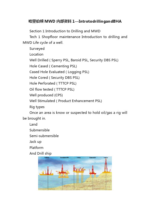
哈里伯顿MWD内部资料1—IntrotodrillingandBHASection 1 Introduction to Drilling and MWDTech 1 Shopfloor maintenance Introduction to drilling and MWD Life cycle of a well.SurveyedLocationWell Drilled ( Sperry PSL, Baroid PSL, Security DBS PSL)Hole Cased ( Cementing PSL)Cased Hole Evaluated ( Logging PSL)Hole Cored ( Security DBS PSL)Hole Perforated ( TTTCP PSL)Oil flow tested ( TTTCP PSL)Well produced (CPS)Well Stimulated ( Product Enhancement PSL)Rig typesOnce an area is know or suspected to hold oil/gas a rig will be brought in.LandSubmersibleSemi-submersibleJack upPlatformAnd Drill shipupLand Rig Jacksub Semi Submersibleship Platform DrillDrilling the well.the well is created by drilling a hole into the earth with an oil rig which rotates a drill bit.To drill the well,The drill bit, aided by rotary torque and the compressive weight of drill collars above it, breaks up the earth.Drilling fluid (aka "mud") is pumped down the inside of the drill pipe and exits at the drill bit and aids to break up the rock, keeping pressure on top of the bit, as well as cleaning, cooling and lubricating the bit.The generated rock "cuttings" are swept up by the drilling fluid as it circulates back to surface outside the drill pipe. Then go over "shakers" which shakes out the cuttings over screens allowing the good fluid to return back into the pits. Watching for abnormalities in the returning cuttings and volume of returning fluid are imperative to catch "kicks" (when the pressure below the bit is more so than above causing gas and mud to come back up uncontrollably) early.The pipe or drill string to which the bit is attached is gradually lengthened as the well gets deeper by screwing in several 30-foot (10 m) joints of pipe at surface. Usually joints are combined into 3 joints equalling 1 stand. Some smaller rigs only use 2 joints and newer rigs can handle stands of 4 joints.This process is all facilitated by a drilling rig which contains all necessary equipment to circulate the drilling fluid, hoist and turn the pipe, control downhole pressures, remove cuttings from the drilling fluid, and generate onsite power for these operations.Components on the Rig.Travelling Block – supports drill pipeMast – supports block and drill pipeDog House – contains driller controlsTop Drive – turns drill pipe from travelling blockRotary Table – turns drill pipe via Kelly on deckKelly – special shaped pipe used with rotary tableDraw works – cable spool for travelling blockStandpipe – drilling fluid pipe attaches to flexible hoseTongs – used to torque drill pipe joints (old Style)Iron Roughneck– portable torque machine for rig drill string components ?Slips – used to suspend drill pipe without damage BOP – blow out preventer – control and releases formation fluid pressure ?Drilling fluid equipment – mud pumps, pits, and shakersTop driveKelly Pipe driveon RoughneckSlipsIrBOPMud SystemSperry provides directional drilling services to drill the well. On customer requirements the BHA, Bottom hole assembly components will be loaded to the rig to drill the well.The BHA can contain Directional drilling, rotary steer able,MWD and LWD tools depending on customer requirement. Sperry can also provide surface data logging (mud engineers). Components within the BHAIf they want to rotary drill with directional control then GeoPiltot for Sperry is used, the competitors all have their own rotary steer able tool on the market also.GeoPilot rotary steer able tool.Mud MotorExtensively used to steer the well are mud motors, whilst drilling with mud motor the term is sliding as the drill string does not rotate, only the bit It is a cheaper and more robust option than GeoPilot but more limited in certain complex drilling applications.A positive displacement motor is designed to provide rotational energy to the bit. It does this by translating the hydraulic energy contained in the mud as it flows through the drill string, into torsion which causes the bit to rotate. The bit will then rotate at a velocity which is dependant upon the flow-rate of the fluid through the motor.A motor consists of a rotor and a stator. The stator will always have one more lobe than therotor, i.e.:The cavity between the rotor and stator is the fluid path. The rotor and stator are arranged on a helix along the length of the power section. This path is always rotating around the central axis as the hydraulic pressure on the rotor causes it to rotate. An adjustable bend on themotor provides the steering ability.ud motor.MBHA Components.AGSAdjustable Gauge stabiliser. These can help to build/Steer angle, not always in the BHA design.BHA ComponentsJars. These can be triggered to try and free a drill string when stuck in hole.StabilisersStabilisers are designed to keep the BHA at a standoff from the borehole wall and also to keep the BHA from bending more than necessary.X-oversUsed to step up or down or connect from pin/box connectionsNMDC (non mag drill collar)Provides spacing between the directional sensor and the steel drill pipe.UBHO subs StabilizersX-oversDrill collars (NMDC - Pony) ?Universal bottom hole orientationReamersRoller Reamers are used in drilling operations to optimize hole circumferenceFloat subsActs like a one way valve for the drilling fluid.MWD/LWD in the BHA.Uses and Benefits:Accurate drill string / bit positionDrill string Steering, trajectory control for geosteeringGeological measurements, formation evaluationDrilling process efficiency, hazard avoidanceServices offered are D/GWD, directional gamma only. (MWD) To full formation evaluation with LWD sensors. The basic and most fundamental service we provide, the building block to which all other services come after is directional control and surveys. Directional control and surveys are the most important service provided.Types of tools and sensors:Directional – provides survey informationBus Masters – Controls toolstring, stores dataFormation Evaluation – Natural gamma, r esistivity, spectral formation density, neutron porosity, acoustic properties and porosityDrilling Efficiency – Pressure, vibration, hole size, rotary steer ableTo transmit data to the surface a telemetry system is used and is covered in detail in the telemetry section.Tool sizes are provided in 3 3/8”, 3 ?”, 4 ?”, 6 ?”, 6 ?”, 7 ?”, 7 ?”, 8”, 9 ?”Collar/hole size.The basic service/environment specifications are:Standard – rated to 150 deg C temp, 10k lb/min flow,19000 psi pressureSolar – High Temp system – 180 deg CHP – High Pressure – 25000 psiHF – High Flow – 20k lb/min flowA surface system is required offshore, using surface sensors to track stand pipe pressure and track tool string depth for logs and surveys.The surface PC has the following functions offshore.To initialize tool, download operational parameters, read stored data, receive and display real-time data, process data, generate logs.Types:Current - Insite (windows based)Previous - (now obsolete) –ISC (DOS), MSC(UNIX), PCDWD(DOS)At the rig site the engineers will prepare the tool to drill the well using the following steps.Make up tool, connect and download, run the tool and decode real-time data, after pulling out of hole connect and read the tool, process recorded data, generate logs.The download is used to setup the tool then acquire data and performed by a cable link to tool busmaster. It is performed while tool is in rotary table before it is run and on deck also used as a diagnostic test in the shop.Our tools use a two line system, power/signal and ground line (which is actually the collar). The system Uses Manchester 1553 protocol for communication signal which is superimposed on the DC power level. All down hole communications are controlled by the busmaster.Other Halliburton Product lines that make up Halliburton ESG (energy services group)Sperry Drilling Services ( that’s us!)Security DBS – bits, core barrelsBaroid – drilling mud servicesLogging – wireline loggingCementing – wellbore cementingTTTCP / CPS – wellbore test & production servicesProduct Enhancement – well stimulation servicesWith all these product lines Halliburton can offer services all the way through the well life cycle.。
旋转导向系统研讨会

Drill faster while steering and reduce wiper trips
string are reduced
Smoother Hole
Tortuosity of well bore is reduced by better steering
– PDM vs RSS
Benefits of RSS
• Less risk of being differential stuck
– Motor BHA stays non-rotated while sliding – RSS BHA rotates all the time
• Some RSS systems has non-rotating sleeves • Some RSS systems has all external parts rotates
– Slow rate of penetration (ROP) while sliding – Orienting mud motor for steering is time consuming – Unable to transfer weight to bit due to high friction – Pipe buckling while sliding – Increase differential sticking risk while sliding – Bit aggressiveness dependent – Introduce micro dogleg
Benefits of RSS
• Overcome pipe buckling issue with sliding mode
哈利伯顿

电缆遥测系统 4 遥测伽玛(D4TG -A)仪器编号:3.74500量纲与额定值电气技术规格机械强度测量点/记录点68.9”伽玛遥测仪(GTET-I )仪器编号:10129021量纲与额定值测量校准3.63”电气技术规格测量点/记录点补偿谱自然伽玛射线仪(CSNG-I TM)仪器编号:101319859量纲与额定值双源距中子测井仪器(DSNT-I TM),insite仪器编号:101291227量纲与额定值校准频谱密度测井仪(SDLT-I TM),insite仪器编号:101291225量纲与额定值校准机械强度测量点双侧向测井仪(DLLT-1)仪器编号:101322326量纲与额定值机械强度微球形聚焦测井仪(MSFL)阵列电阻率补偿仪(ACRt TM)仪器编号:10138722校准时间—温度范围组合井眼补偿仪(BCAS-I),I nsite井眼参数硬件特性机械强度测量点/记录点wavesonic TM-交叉偶极子声波检测器(WSTT-l)井眼参数硬件特性测量机械强度增强显微成像仪(XRMI-B)井眼参数硬件特性机械强度环形水下声波扫描测井仪(CAST-V TM)仪器编号:707,55600(图像模式)量纲与额定值测量测量点环形水下声波扫描测井仪(CAST-V TM)仪器编号:707,55600(套管井模式)量纲与额定值测量校准测量点井孔特性仪(BHPT TM)仪器编号:100136395量纲与额定值井眼参数硬件特性校准膨胀封隔式组合测井仪(ICT)仪器编号:101355467量纲与额定值膨胀系数定向测井仪(IDT-l TM)仪器编号:101355419量纲与额定值测量校准测量点(从仪器底部开始测量)DITS多导体旋转接头测井仪(MCSA-D)仪器编号:707.71628量纲与额定值机械强度井下张力装置(DTD),DITS Version仪器编号:707.31411量纲与额定值DITS 套管接箍定位仪(DCCL-A)仪器编号:3.33969量纲与额定值硬件特性测量井下张力装置(DTD),DITS Version仪器编号:707.31411量纲与额定值DITS 套管接箍定位仪(DCCL-A)仪器编号:3.33969量纲与额定值硬件特性测量。
东海水平分支井悬空侧钻技术
东海水平分支井悬空侧钻技术赵志付;孙乾坤;段宾【摘要】随着油藏开发要求的不断提高,单靠增加水平段长度难以有效地提高油藏动用程度和单井产量,多分支水平井具有增加油藏泄油面积、提高单井产量、节约钻井费用等优点,是高效开发油气藏的理想井型.但是水平分支井侧钻存在失败以及虽然侧钻成功但作业时间过长的情况,海洋钻井作业高成本的矛盾十分突出.此文总结了东海使用旋转导向工具侧钻水平分支井的措施,结合东海水平分支井侧钻实践,总结了成功进行水平分支井作业的关键在于按照合理的施工程序操作,并在预定侧钻位置提前造大狗腿斜坡,有利于侧钻时更容易形成新井眼,提高悬空侧钻成功率.【期刊名称】《海洋石油》【年(卷),期】2018(038)003【总页数】5页(P56-60)【关键词】悬空侧钻;划槽;造台阶;控时钻进;局部狗腿【作者】赵志付;孙乾坤;段宾【作者单位】中海油能源发展股份有限公司上海工程技术分公司,上海200335;中海油能源发展股份有限公司上海工程技术分公司,上海200335;中海油能源发展股份有限公司上海工程技术分公司,上海200335【正文语种】中文【中图分类】TE52水平分支井是在一个水平主井眼内钻出两个或者多个水平分支井眼的水平井,是水平井与侧钻技术的集成和发展[1,2],该技术在提高低渗透、特低渗透气田开采率方面发挥了重要的作用。
我国东部海域油气田迄今为止勘探开发揭示的油气资源潜力主要赋存于深层—超深层的常规低渗—近致密气的领域[3],具有埋藏深(垂深3 500 m以下)、地质成因复杂的特点[4]。
近年在东海主要利用旋转导向工具实施水平分支井钻进,其中H油田是近两年开发的新油田,为了提高低渗储量动用程度,部署实施多口水平分支井,水平分支井难点之一较普通水平井来说在于悬空侧钻。
因此,本文总结了悬空侧钻作业注意事项,并从H油田不同井悬空侧钻成功与失败的案例中,分析提高悬空侧钻成功率的一些关键点,着重分析在预定侧钻位置提前造大狗腿斜坡的影响。
旋磨操作介绍

旋磨操作介绍旋磨操作介绍?公司简介波士顿科学公司BostonScientific公司总部设在美国马萨诸塞州波士顿地区的内提克市全球共有约24,000名员工业务遍及全球各个国家作为全球医疗技术行业创新领导者,波士顿科学每年研发投入资金达8.86亿美金在世界范围内拥有超过15,000项授权专利介绍内容设备连接操作技巧“鸡尾酒”配方&常见问题指引导管&磨头选择策略旋磨的手法消融技巧消融时的反馈交换过程设备连接Priortouse,pleaseseethecomplete‘DirectionsForUse’formorei nformationonIndications,Contraindications,Warnings,Precaution s,AdverseEventsandOperator’sInstructions.系统连接连接供气管和氮气瓶,每台手术保证氮气瓶内压力至少为500PSI/3447.5kPa;经压力表输出到主机的压力保持在90-110PSI/620.55kPa-758.45kPa连接DyanaglideTM脚踏开关软管–绿管和蓝管接在主机背板上,粉色管接在主机前面板上主机接通电源打开开关连接推进器光纤接头连接推进器空气管将推进器盐水输入管和生理盐水袋连接并加压Priortouse,pleaseseethecomplete‘DirectionsForUse’formorei nformationonIndications,Contraindications,Warnings,Precaution s,AdverseEventsandOperator’sInstructions.旋磨导管和推进器连接旋磨导管和推进器连接好以后再移除磨头保护套Priortouse,pleaseseethecomplete‘DirectionsForUse’formorei nformationonIndications,Contraindications,Warnings,Precaution s,AdverseEventsandOperator’sInstructions.测试脚踏开关对系统的控制调整磨头的转速理想的转速160,000-180,000转/分150,000-170,000转/分磨头尺寸1.25-2.0mm2.15-2.5mm注意:避免磨头接触毛巾,纱布,手套等系统测试(体外)D.R.A.W.–体外测试Drip–盐水有无从推进器和磨头出滴出Rotate–磨头旋转且转速稳定Advancer–推进器把手可以自由移动Wire–推进器尾部导丝可见,磨头旋转时导丝无法移动必须要有盐水注入的条件下才可操作旋磨推进器,用于冷却和润滑推进器。
- 1、下载文档前请自行甄别文档内容的完整性,平台不提供额外的编辑、内容补充、找答案等附加服务。
- 2、"仅部分预览"的文档,不可在线预览部分如存在完整性等问题,可反馈申请退款(可完整预览的文档不适用该条件!)。
- 3、如文档侵犯您的权益,请联系客服反馈,我们会尽快为您处理(人工客服工作时间:9:00-18:30)。
心环总成组成了精细、紧凑经久耐用的计算机控制的偏心单元,两
个偏心环驱动驱动轴偏离钻具中心,致使钻头产生偏斜力,从而实 现全部旋转的导向钻进模式。
Geo-Pilot® 旋转导向钻井系统是由Sperry和 JOGMEC公司(日本石油天然气和金属国家股份有 限公司)共同开发的。
Geo-Pilot® 的基本构成
ShortGauge Bit
ExtendedGauge Bit
3/4” 3/4”
Spiraling Results 螺旋井眼的危害
Excess Sliding Friction 摩擦系数大 Poor sliding ROP, weight transfer Casing hangs up
Logging tools won’t go to bottom
• • • • • •
Rotary Steerable Systems
•
PUSH THE BIT 推靠式
– Power Drive
•
POINT THE BIT 指向式
– GeoPilot
Geo-Pilot® 的工作原理 - 指向式旋转导向钻井系统
Geo-Pilot® 的外筒装有两个偏心环,一个位于另一个的内部,该偏
不是滑动,所以不会损坏滚轮更不会增加软地层的摩擦阻力
GP9600 Reference Stabiliser 支撑扶正器
12”
14 1/8”
Reference Stabiliser 支撑扶正器
GP9600
12”
14 1/8”
井眼尺寸
GP9600 GP7600 12-1/4” 8-1/2”
工具外径
9-5/8” 7-3/8”
制井眼轨迹,进行高水平的地质导向作业
近钻头井斜和角方位 伽玛@ 3 英尺
近钻头角方位伽玛 – 目前市场距离钻头最近
闪烁器 加速器与温度 传感器 处理器
120°
120°
120°
闪烁器 闪烁器
e 耐压套
巡航模式
近钻头数据回到允许范 围,GP工具自动降低受 力,阻止井斜继续增大
90.0 89.8 89.7 89.6 89.7
Minimizes destructive motion and vibration 井下震动最小
•
FullDrift™ Drilling Systems
不同钻头的效果比较
Comparison of short-gauge and long gauge wood bits Long-gauge bit generates a straighter hole
Cement Quality 固井质量
Gravel Pack Success 砾石充填
Real-Time Communications 实时通讯
Geo-Span
DOWNLINK SYSTEM
®
On-the-fly
to 30,000+ feet(9143m)
Geo-Pilot® Rotary Steerable System Family 全系列
软地层 砂岩 / 页岩 5 - 10 Kpsi
硬夹层 白云岩 / 菱铁矿 25 - 35 Kpsi
除此之外,PDC钻头接触井底、吃入地层不再稳定,同 时由于钻头的水利喷射对软地层的冲刷,也会造成钻头 的失稳。
若能监测到钻具的严重振动,立即提起钻并停止一切动 作,来耗散和释放钻具的能量。
硬夹层
钻井
软地层 砂岩 / 页岩 5 - 10 Kpsi
REMEMBER: No Pumps when break seals, normally in Casing
注意: 润滑密封时不开泵,通常在套管里进行
胶塞-套管附件的钻进
如果GP的密封没有润滑, 请先GP的密封润滑. 注意: 润滑密封时不开泵. 钻具中灌满泥浆, 建立循环, 然后缓慢下放钻具直至探到水泥塞.
方法
钻进硬夹层
• 一旦确认钻头进入硬夹层大约0.5米,首先逐渐缓慢 地增加钻压,然后如果需要的话,微调RPM,优化钻 井参数,减少钻具的振动。 • 通常钻遇硬地层,保持较高的WOB和较低的RPM。 • 重新建立新的排量大小,以便清洗井眼。 例如:对 于较厚的硬夹层钻进可用较低的排量,但要注意硬夹 层上部的软地层的冲蚀和兼顾硬地层用大排量时而造 成的水力反冲作用从而使作用在钻头上的有效钻压大 打折扣。 • 保持此钻井参数继续钻进。
裸眼钻进:
•
保持所推荐的最好的钻井程序
•
•
始终保持通讯畅通,下发指令前先通知司钻
必要时要进行耗时钻进
•
•
保证钻具提离井底时始终旋转
通常不需要进行倒划眼,但软硬交错的地层需要倒 划眼切缓慢通过
起钻
起钻或入井前保证 Geo-Pilot 设置力为零(中性状态) 对于难以通过井段,采用高钻速、低钻压、适当的排量, 进行划眼/倒划眼起钻 若遇到憋泵现象,要立即停泵并从地面释放压力,以保 护Geo-Pilot的工具密封不受到损坏(密封耐压最高2000 PSI)
近钻头井斜表明工具面 和受力不需改变
90.0 90.0 90.0 90.0
89.8
89.9
90.0
90.0
90.0
90.0
近钻头井斜超出允许范围, GP自 动采用高边和最大的力改变钻具状 况
受力回到初始状态继续 钻进
Long Gauge Bit 长保径钻头
•
Centralizes bit so hole is drilled straighter 井眼光滑
Ambiguous Logging Responses 电测差 Unstable bit 钻头寿命短 Higher vibration Cuttings Bed Traps 岩屑床 Hole hard to clean Avalanche Stuck Pipe Poor Mud Displacement More failures Shortened bit life More trips
外筒、芯轴和控制单元
近钻头井斜和近钻头角方位伽玛传感器(距离钻头1米) 地面收发指令系统 长保径钻头 (专用钻头;接头配合常规钻头)
Geo-Pilot 原理示意图
芯轴偏离中心轴
指向式旋转导向工具,造斜率受地层因素很小
中性位置
造斜力最大
造斜力中等
“24小时连续钻进” – 发指令不需停止钻进 具有巡航模式 精细的工具面控制、受力大小的选择 近钻头角方位伽玛和井斜传感器,距离钻头最近,可以实现精确控
Max Overpull Ultimate Overpull Max RPM: Design DLS:
30,000 ft.lbs
120,000 lbs 580,000 lbs 250 6 deg/30m
Break in the Seals 润滑密封
•
Before Circulation commenced above the cement, ensure that the Seals are broken on the GP tool. 作业之前先进行润滑密封 Rotate at 5rpm, 10rpm, 20rpm, 40rpm, 60rpm for every 2 min 每5,10,20,40,60转各自进行2分钟,共计10分钟左右
胶塞-套管附件的钻进
钻穿套管鞋之后, 钻具停止旋转, 在套管鞋处上下多次活动钻具, 确保胶塞 碎屑不粘附在GP上..
ቤተ መጻሕፍቲ ባይዱ
如果胶塞的钻进中非常缓慢,可将钻压提高到8-10吨,同时将转速提高到 80rpm
钻开新地层3-6米(如果需要快速增斜,可以在出少于2米的新地层), 将钻具 提回套管内, 确定GP在套管鞋处自由通过, 无杂物等缠绕在GP的支撑扶正 器上, 或者GP支撑扶正器的下部, 或者钻头等, 其现象类似憋泵. 如有此种情况发生, 请小心进行下一步操作. 采用较好的所在地区的经验清 洗套管鞋附近井段, 确保其光滑过渡. 注意钻具中的扶正器, 在套管鞋处要 小心缓慢通过.
Mud Flow Inlet Connection:1502
2
Reference Stabiliser 支撑扶正器
•
Maintains 200 lbs of force on formation wall and are spring loaded - No
hydraulic pistons to blow apart on sudden step downs in hole diameter. 支撑弹簧可承受地层200lbs(89kg) 的力,无任何水力活塞等随井径的变
硬夹层 白云岩 / 菱铁矿 25 - 35 Kpsi Sand / Shale 5 – 10 Kpsi
硬夹层
钻井
方法
钻出硬夹层 • 当PDC钻出硬夹层时,ROP会缓慢增加,但钻井参数可能会 有明显的变化 • 在穿过硬地层的时候,不要立即改变参数提高钻速,避免使用过 高钻压将残余的硬夹层压碎从而导致硬块在井底滚动。 • 而是保持较小的RPM小钻压钻进大约0.5米,以防钻头包径牙 齿的损坏,直到钻头完全进入软地层。减少排量,以防在硬夹 层下部形成一个硬台阶,难以起钻。 • 一旦钻出硬夹层,缓慢调整钻井参数,如同前面钻进软地层的 一样,注意观察有大外径的钻具全部通过硬夹层。
140°C 20,000 psi 20 g rms 5-500 Hz None 40 bbls (medium) 0 degree
Mechanical specifications 机械性能
•
Max WOB:
45 K lb.f (limitation by the M/LWD)
