108-0740-001;中文规格书,Datasheet资料
皮圈尺寸名录
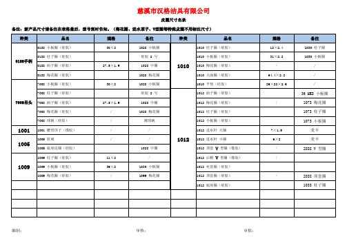
备注:新产品尺寸请备注在表格最后,型号到时告知。
(梅花圈、进水顶子、V型圈等特殊皮圈不用标注尺寸)
备注:新产品尺寸请备注在表格最后,型号到时告知。
(梅花圈、进水顶子、V型圈等特殊皮圈不用标注尺寸)
备注:新产品尺寸请备注在表格最后,型号到时告知。
(梅花圈、进水顶子、V型圈等特殊皮圈不用标注尺寸)
备注:新产品尺寸请备注在表格最后,型号到时告知。
(梅花圈、进水顶子、V型圈等特殊皮圈不用标注尺寸)
备注:新产品尺寸请备注在表格最后,型号到时告知。
(梅花圈、进水顶子、V型圈等特殊皮圈不用标注尺寸)
备注:新产品尺寸请备注在表格最后,型号到时告知。
(梅花圈、进水顶子、V型圈等特殊皮圈不用标注尺寸)
备注:新产品尺寸请备注在表格最后,型号到时告知。
(梅花圈、进水顶子、V型圈等特殊皮圈不用标注尺寸)。
575-8;575-4;6092;6091;476-2;中文规格书,Datasheet资料
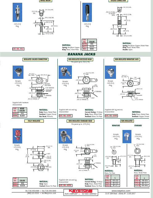
1BANANA JACKSTel (718)956-8900•Fax (718)956-9040(800)221-5510•kec@31-0720th Road –Astoria,NY 11105-2017RoHS COMPLIANT ~ISO 9001CERTIFIED®MATERIAL:Spring:Beryllium Copper Body:Brass,Silver PlateCAT.NO.452MATERIAL:Spring:Beryllium Copper,Nickel Plate Body:Brass,Nickel Plate Handle:Nylon.120(3.0)Plug.120(3.0)Plug.603 [15.3].153 [3.9]DIA..187 [4.8]DIA..110 [2.8].094 [2.39].078 [1.98]DIA..120 [3.1]DIA..290 [7.4].050 [1.27] DIA.TO ACCEPTWIRE..190 [4.9]DIA..104 [2.7] DIA..440 [11.2].480 [12.2].120 [3.1] DIA..290 [7.4]CAT.NO.COLOR 6076RED 6077BLACK 451NONESOLDER CONNECTIONSWAGE MOUNT MATERIAL:Body:Brass,Nickel Plate Terminal:Copper,TinnedAccepts .120(3.0)Plug.550[14.0].062 [1.57].312 [7.9]HEX..250 [6.4].106 [2.7]DIA.THRU10-32 THREADNUTTERMINAL MATERIAL:Body:Brass,Nickel Plate Terminal:Copper,Tinned Hex Head:PhenolicMATERIAL:Current Rating:15Amps Body:Brass,Nickel Plate Terminal:Brass,Tin PlateMATERIAL:Brass,Tin PlateMATERIAL:Body:NylonContact:Brass,Tin PlateCAT.NO.6096MATERIAL:Brass,Nickel PlateCAT.HEAD NO.COLOR 6093RED 6094BLACKCAT.NO.COLOR 6091RED 6092BLACKCAT.NO.6095STANDARDFULLY INSULATED Fits panel up to .375(9.6)CAT.NO.L 575-4.218(5.5)575-6.265(6.7)575-8.350(8.9)CAT.NO.L 476-2.125(3.2)476-3.165(4.2)476-4.187(4.7)Accepts .120(3.0)PlugAccepts .175(4.5)PlugFits panel up to .312(7.9)Accepts .175(4.5)PlugMATERIAL:Current Rating:15Amps Body:Brass,Nickel Plate Terminal:Brass,Tin PlateAccepts .175(4.5)PlugAccepts .175(4.5)PlugNON-INSULATED MINIATURE JACKMINIATUREINSULATED SOLDER CONNECTIONCAT.NO.6090.562[14.3].500[12.7].437[11.1].156[4.0].163[4.2]DIA.THRU.250-28 THREADNUTTERMINAL MOLDED HEX HEADFLAT WASHER SHOULDER WASHER.375 [9.5].406 [10.3].093 [2.36].163 [4.2] DIA.THRU.250-32 THREADTERMINALNUT.312[7.9].500 [12.7].375 [9.5]NUT.125 [3.2]TERMINALNUT.250-32 THREAD.163 [4.2] DIA.THRU.135 [3.5]DIA.L.075[1.91].218[5.6]DIA..106 [2.7]DIA.THRU.203 [5.2]DIA..093 [2.36].312 [7.9]DIA..163 [4.2] DIA.THRUL.182[4.6].937[23.8].433[11.0]DIA..187[4.8].234[6.0].468[11.9].093[2.36]DIA..312-32THREAD NUT Supplied with hardware UnassembledSupplied with nut and lug.UnassembledSupplied with lug and nut.UnassembledSupplied with nut and lug.UnassembledNON-INSULATEDAccepts .175(4.5)PlugNON-INSULATED STANDARD HEADNON-INSULATED RECESSED HEAD分销商库存信息:KEYSTONE-ELECTRONICS575-8575-46092 6091476-2476-4 575-660766077 60946093。
海外规格仕样书第4版(中文)
4.在机铭板上标示出以下内容 ・制造者名 ・制造年月 ・形式以及model编号 ・定格电源电压(电压、位相、周波数、最大负荷电流、etc) 在电源上不可以用「AC200V」表示,而要用「~200V」表示 ・气压(定格压力) ・原产地表示(MADE IN JAPAN等) 注)FA标准机铭板: 4—710—156—01(大—11) 带孔、by三立产业 EN60204 UL1740
8.盖子、马达框架、trans core、电装品筐体、以及接续管等的金属部, 如果和地线或金属接触,会导致和物品本身的导通。
EN60204、UL1740
7/28
要求事项
1.电源切断装置要使用得到认可的漏电断路器、自动断路器、线路保护器 EN60204、UL1740 2.主断路器的定格要遵循以下事项。 EN60204、UL1740 a)电流容量:最大负荷电流的115%以上,或者使用的导线的要求容许电流以下 (14配线以及电路——参照17) b)切断容量:在机器上使用的马达中,最大马达的 rotor rock电流+其他装置的 最大负荷电流以上 3.电力引入线(一次电源)要直接和断路器连接 EN60204、UL1740 4.电源切断装置遵循一下事项。 EN60204、UL1740 (a)安装把手,方便从外部操作 (b)把手的中心高度在0.6~1.9以内 (c)要有OFF锁定机能.(可以上锁的构造) (d)门关上时要有ON/OFF的明确指示 (e)ON/OFF可以用「O」也可以用「I」来表示 (f)接地导线以外所有的相要同时切断 (g)主断路器上如果没有OFF锁定机能,要在负荷侧设定带钥匙的主开关。
贵社 check
本社 check
备注
① 外 观 以 及 构 造 的 规 定
4/28
LF356NNOPB,LF356M,LF356H,LF156H,LF256H,LF356MX, 规格书,Datasheet 资料
capability
Applications
n Precision high speed integrators n Fast D/A and A/D converters n High impedance buffers n Wideband, low noise, low drift amplifiers
LF155/LF156/LF256/LF257/LF355/LF356/LF357 JFET Input Operational Amplifiers
December 2001
LF155/LF156/LF256/LF257/LF355/LF356/LF357
JFET Input Operational Amplifiers
1.5
12 5 12
LF257/ LF357 (AV=5)
1.5
50 20 12
Units µs
V/µs MHz
Simplified Schematic
*3pF in LF357 series.
BI-FET™, BI-FET II™ are trademarks of National Semiconductor Corporation.
300˚C
300˚C
Dual-In-Line Package
Soldering (10 sec.)
260˚C
260˚C
260˚C
Small Outline Package
Vapor Phase (60 sec.)
厦门伯特BT108说明书

第三章 BT108操作说明一 面板说明① 测量值显示窗;在参数设定状态下显示参数符号;② 给定值显示窗;在参数设定状态下显示参数值;③ 给定值/参数设定键;点按一下进入或退出给定值设定状态;持续按该键3秒再放开,仪表进入参数设定状态。
在参数设定 状态下,点按该键选下一个参数;④ 左移位/启动或取消自整定快捷键;在设定状态下,用于移动光标快速选择需要设定的数位;在正常测量状态下,按该键2秒 钟,仪表进入自整定状态(AT 灯亮);在自整定状态下,按该 键2秒钟取消自整定(AT 灯灭);如果仪表已经执行过一次自 整定,该键的快捷功能被禁止,以避免误操作。
确实需要重新 整定时,请参看后文参数Cont 的说明; ⑤ 数值减键;在设定状态下,用于减小数值; ⑥ 数值加键;在设定状态下,用于增加数值; ⑦ 自整定状态指示灯(AT );该灯亮时,表明仪表处于自动整定控 制参数状态中;⑧ 主输出状态指示灯(OUT ); ⑨ 报警1状态指示灯(ALM1); ⑩ 报警2状态指示灯(ALM2);仪表上电时,上显示窗显示仪表基本型号108,下显示窗显示软件序列号bt ××⑧①②③④⑤⑥ ⑨⑦⑩二 操作流程(PLoc=1008时)1.给定值设定(例:将给定值由30.0修改为100.0)注意:SET 键是多功能键,按一下即放开进入给定值设定状态,如果按下时间超过3秒钟,将进入参数设定状态(见下文)。
键也是多功能键,按该键保持2秒钟,仪表进入自动整定控制参数状态,AT 指示灯亮;在自整定状态下,按键 保持2秒钟取消自整定,AT 指示灯灭。
理论上所有的控制系统都需要经过整定才能获得好的控制效果,BT108仪表在 出厂时预置了一组控制参数,如果控制效果可以达到工艺要求,可不必启动自整定,否则需要启动自整定功能。
自整定 可以在设备首次运行时启动,也可以在运行中启动。
在运行中启动时,应使测量值至少小于(反作用调节)或大于(正 作用调节)给定值10℃。
TVR07471中文资料
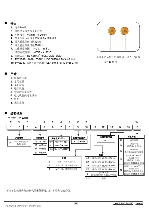
产品类型 TVR 兴勤压敏电阻器 TVR 系列
本体尺寸 07 10 14 20 Φ 7mm Φ10mm Φ14mm Φ20mm
压敏电压 (V1mA ) 180 241 18x10 V=18V 24x10 V=240V
2 1 0
压敏电压公差 K ±10%
内部控制代码 01~ZZ D W K 包装
可选后辍
S
N
备注:包装及内部控制代码未使用时, 第 11 码为可选后辍。
54
2013.03
产品规格与数据若有变更,恕不另行通知
压敏电阻交易www.unit-ic.com
结构与尺寸
S 型 (直脚)
D T
A
Max. 3.0
P W
仰视图
P
d
L
W
(单位:mm) 系列 TVR07-D TVR10-D TVR14-D TVR20-D D 7.5~9.5 12.0~14.0 16.0~18.5 22~24.5 Lmin. 26.5 26.5 26.5 22.5 d 0.6±0.02 0.8±0.02 0.8±0.02 1.0±0.02 P 5±1 7.5±1 7.5±1 10±1 Amax. 12.5 17.5 21.5 28.5
请见电气特性表
Tmax.
W
F 型 (Y型引脚)
D T
Max.3.0
A
MAX 30
0
P
C d
(单位:mm) 系列 TVR07-D TVR10-D TVR14-D TVR20-D D 7.5~9.5 12.0~14.0 16.0~18.5 22~24.5 Cmin. 20 20 20 20 d 0.6±0.02 0.8±0.02 0.8±0.02 1.0±0.02 P 5±1 7.5±1 7.5±1 10±1 Amax. 12.5 18.0 22.0 29.0
人民电器 RDM108系列塑料外壳式断路器 产品说明书

产品概述RDM108系列塑料外壳式断路器适用于交流50Hz/60Hz额定工作电压至660V额定电流0.1A~63A的线路中,作为小容量电动机和线路的过载及短路保护用,并可在正常情况下作为不频繁操作的线路转换或电动机直接启动之用。
断路器可在AC-3负载下作为直接起动和分断电动机的全压启动器,并对电动机进行过载和短路保护之用。
产品符合:GB/T 14048.2、GB14048.4 标准。
,,选型指南结构特征RDM108-20断路器上有辅助触头,RDM108-32断路器外可组装一个辅助触头组。
RDM108-63断路器内可装个辅助触头组RDM108-32和RDM108-63脱扣机构采用了速闭、速断结构,使断路器具有限流特性。
断路器具有双金属片式反时限延时脱扣器和电磁式瞬时脱扣器。
过载脱扣器具有温度补偿装置。
在产品正面有脱扣电流调节指针,可在规定范围内调整脱扣电流。
RDM108-20、RDM108-32和RDM108-63断路器操作方式分别为按钮操作,旋钮操作及手柄操作,为板前接线、板前安装式。
RDM108-20、32型断路器具有安装卡板,可直接嵌装在35mm宽的标准导轨上。
一。
正常工作条件和安装条件□ 海拔:安装地点的海拔高度不超过2000m;□ 周围空气温度:不超过+40℃且其24h内的平均温度值不超过+35℃,周围空气下限为-5℃;□ 污染等级:3级;□ 安装类别:断路器主电路为Ⅲ,辅助电路和控制电路为Ⅱ;□ 断路器应安装在无爆炸危险和无导电尘埃、无足以腐蚀金属和破坏绝缘的地方;□ 在没有雨雪侵袭的地方。
067主要技术参数断路器过流调节范围见表1断路器主要技术数据见表2表1068外形及安装尺寸RDM108-20型断路器外形及安装尺寸RDM108-32型断路器外形及安装尺寸表3断路器过电流脱扣特性见表3表4断路器过载脱扣器所具有的温度补偿性能见表4069用户订货时必须说明如下事项:断路器的型号、名称;断路器的额定电流;断路器的附件名称、规格、组合代号;采用欠电压脱扣器和分励脱扣器时,应注明工作电压(或控制电源电压)的电压值;数量例如:RDM108-63,3极,电动机保护用63A ,50台,无辅助触头。
GBPC108中文资料
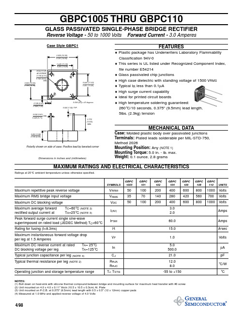
GBPC1005 THRU GBPC110GLASS PASSIVATED SINGLE-PHASE BRIDGE RECTIFIERReverse Voltage -50 to 1000 Volts Forward Current - 3.0 AmperesFEATURES♦ Plastic package has Underwriters Laboratory Flammability Classification 94V-0♦ This series is UL listed under Recognized Component Index,file number E54214♦ Glass passivated chip junctions♦ High case dielectric with standing voltage of 1500 V RMS ♦ T ypical I R less than 0.1µA ♦ High surge current capability ♦ Ideal for printed circuit boards♦ High temperature soldering guaranteed:260°C/10 seconds, 0.375" (9.5mm) lead length, 5lbs.(2.3kg) tensionMECHANICAL DATACase:Molded plastic body over passivated junctions Terminals:Plated leads solderable per MIL-STD-750, Method 2026Mounting Position:Any (NOTE 1)Mounting Torque:5.0 in.- lb.max.Weight:0.1 ounce, 2.8 gramsMAXIMUM RATINGS AND ELECTRICAL CHARACTERISTICSRatings at 25°C ambient temperature unless otherwise specified.GBPC GBPCGBPC GBPC GBPC GBPC GBPC SYMBOLS 1005 101102104106108110UNITSMaximum repetitive peak reverse voltage V RRM 501002004006008001000Volts Maximum RMS bridge input voltage V RMS 3570140280420560700Volts Maximum DC blocking voltage V DC 501002004006008001000Volts Maximum average forward T C =60°C (NOTE 2) 3.0rectified output current atT A =25°C (NOTE 3)I (AV) 2.0Amps Peak forward surge current single sine-wavesuperimposed on rated load (JEDEC Method) T C =60°C I FSM 60.0Amps Rating for fusing (t<8.3ms)I 2t 15.0A 2sec Maximum instantaneous forward voltage drop per leg at 1.5 AmperesV F 1.0Volts Maximum DC reverse current at rated T A = 25°C 5.0DC blocking voltage per legT A =125°CI R 500.0µA Typical junction capacitance per leg (NOTE 4)C J 21.0pF Typical thermal resistance per leg (NOTE 2)R ΘJA 12.0R ΘJC 8.0°C/W Operating junction and storage temperature rangeT J,T STG-55 to +150°CNOTES:(1) Bolt down on heat-sink with silicone thermal compound between bridge and mounting surface for maximum heat transfer with #6 screw (2) Unit mounted on 4.0 x 4.0 x 0.11" thick (10.5 x 10.5 x 0.3cm) Al. Plate(3) Unit mounted on P.C.B. at 0.375" (9.5mm) lead length with 0.5 x 0.5" (12 x 12mm) copper pads (4) Measured at 1.0 MHz and applied reverse voltage of 4.0 VoltsPolarity shown on side of case: Positive lead by beveled cornerCase Style GBPC1Dimensions in inches and (millimeters)4/98。
TL074IDT,TL074IDT,TL074IDT,TL074ACDT,TL074ACDT,TL074ACDT,TL074IYDT,TL074IYDT, 规格书,Datasheet 资料
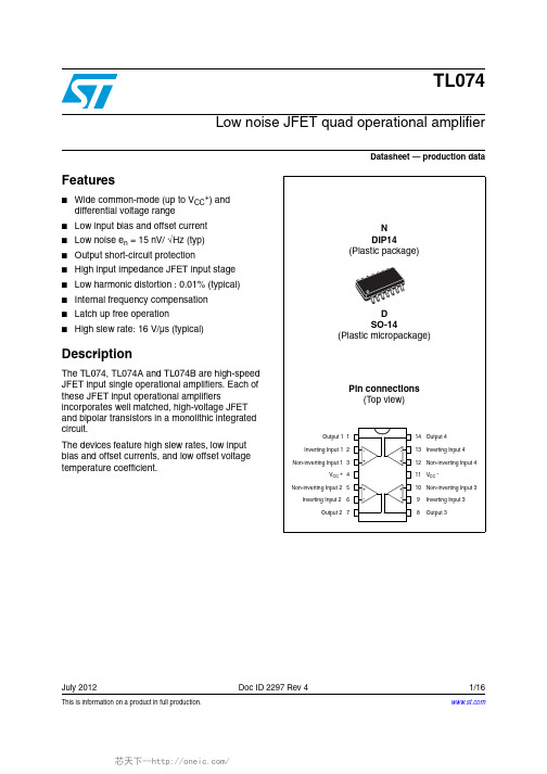
This is information on a product in full production.July 2012Doc ID 2297 Rev 41/16TL074Low noise JFET quad operational amplifierDatasheet — production dataFeatures■Wide common-mode (up to V CC +) and differential voltage range ■Low input bias and offset current ■Low noise e n = 15nV/ √Hz (typ)■Output short-circuit protection■High input impedance JFET input stage ■Low harmonic distortion : 0.01% (typical)■Internal frequency compensation ■Latch up free operation ■High slew rate: 16V/µs (typical)DescriptionThe TL074, TL074A and TL074B are high-speed JFET input single operational amplifiers. Each of these JFET input operational amplifiersincorporates well matched, high-voltage JFET and bipolar transistors in a monolithic integrated circuit.The devices feature high slew rates, low input bias and offset currents, and low offset voltage temperature coefficient.Schematic diagram TL0742/16Doc ID 2297 Rev 41 Schematic diagramTL074Absolute maximum ratings and operating conditionsDoc ID 2297 Rev 43/162Absolute maximum ratings and operating conditionsTable 1.Absolute maximum ratingsSymbol ParameterValueUnitTL074I, AI, BITL074C, AC, BC V CC Supply voltage (1)±18V V i Input voltage (2) ±15V V id Differential input voltage (3)±30V P tot Power dissipation680mW R thjaThermal resistance junction to ambient (4)(5)DIP14SO-1480105°C/W R thjcThermal resistance junction to case (4)(5)DIP14SO-143331°C/WOutput short-circuit duration (6)InfiniteT oper Operating free-air temperature range -40 to +1050 to +70°C T stgStorage temperature range -65 to +150°C ESDHBM: human body model (7)1kV MM: machine model (8)200V CDM: charged device model (9)1.5kV1.All voltage values, except differential voltage, are with respect to the zero reference level (ground) of the supply voltageswhere the zero reference level is the midpoint between V CC + and V CC -.2.The magnitude of the input voltage must never exceed the magnitude of the supply voltage or 15 volts, whichever is less.3.Differential voltages are the non-inverting input terminal with respect to the inverting input terminal.4.Short-circuits can cause excessive heating. Destructive dissipation can result from simultaneous short-circuits on allamplifiers.5.Rth are typical values.6.The output may be shorted to ground or to either supply. Temperature and/or supply voltages must be limited to ensurethat the dissipation rating is not exceeded.7.Human body model: 100pF discharged through a 1.5k Ω resistor between two pins of the device, done for all couples of pincombinations with other pins floating.8.Machine model: a 200pF cap is charged to the specified voltage, then discharged directly between two pins of the devicewith no external series resistor (internal resistor < 5Ω), done for all couples of pin combinations with other pins floating.9.Charged device model: all pins plus package are charged together to the specified voltage and then discharged directly tothe ground.Table 2.Operating conditionsSymbol ParameterTL074I, AI, BITL074C, AC, BCUnit V CC Supply voltage6 to 36VT operOperating free-air temperature range-40 to +1050 to +70°C3 ElectricalcharacteristicsTable 3.V CC = ±15V, T amb = +25°C (unless otherwise specified)Symbol Parameter TL074I,AC,AI, BC,BI TL074CUnit Min.Typ.Max.Min.Typ.Max.V io Input offset voltage (R s= 50Ω)T amb = +25°C TL074TL074ATL074BT min≤T amb≤T max TL074TL074ATL074B3311063137531013mVDV io Input offset voltage drift1010µV/°CI io Input offset currentT amb = +25°CT min≤T amb≤T max51004510010pAnAI ib Input bias current -note (1)T amb = +25°CT min≤T amb≤T max20200203020020pAnAA vd Large signal voltage gain R L= 2kΩ, V o=±10VT amb = +25°CT min≤T amb≤T max50252002515200V/mVSVR Supply voltage rejection ratio (R S= 50Ω)T amb = +25°CT min≤T amb≤T max808086707086dBI CC Supply current, no loadT amb = +25°CT min≤T amb≤T max1.42.52.51.42.52.5mAV icm Input common mode voltage range ±11+15-12±11+15-12VCMR Common mode rejection ratio (R S= 50Ω)T amb = +25°CT min≤T amb≤T max808086707086dBI os Output short-circuit currentT amb = +25°CT min≤T amb≤T max10104060601010406060mA±V opp Output voltage swingT amb = +25°C RL = 2kΩRL = 10kΩT min≤ T amb≤T max RL = 2kΩRL = 10kΩ101210121213.5101210121213.5VSR Slew rateV in = 10V, R L = 2kΩ, C L = 100pF, unity gain813813V/µs4/16Doc ID 2297 Rev 4Doc ID 2297 Rev 45/16t rRise timeV in = 20mV , R L = 2k Ω, C L = 100pF , unity gain0.10.1µsK ovOvershootV in = 20mV , R L = 2k Ω, C L = 100pF , unity gain1010%GBP Gain bandwidth product V in = 10mV , R L = 2k Ω, C L = 100pF , = 100kHz 2323MHz R i Input resistance10121012ΩTHDTotal harmonic distortionf= 1kHz, R L = 2k Ω,C L = 100pF , A v = 20dB, V o = 2V pp )0.010.01%e n Equivalent input noise voltage R S = 100Ω,f = 1kHz 1515∅m Phase margin 4545degreesV o1/V o2Channel separation A v = 100120120dB1.The input bias currents are junction leakage currents which approximately double for every 10°C increase in the junctiontemperature.Table 3.V CC = ±15V, T amb = +25°C (unless otherwise specified) (continued)SymbolParameterTL074I,AC,AI, BC,BITL074CUnitMin.Typ.Max.Min.Typ.Max.nV Hz -----------Figure 2.Maximum peak-to-peak outputFigure 3.Maximum peak-to-peak outputFigure 4.Maximum peak-to-peak output Figure 5.Maximum peak-to-peak outputFigure 6.Maximum peak-to-peak output Figure 7.Maximum peak-to-peak output6/16Doc ID 2297 Rev 4Doc ID 2297 Rev 47/16Figure 8.Input bias current versus free air temperatureFigure 9.Large signal differential voltage amplification versus free airFigure rge signal differential voltageamplification and phase shift Figure 11.Total power dissipation versus freeair temperatureFigure 12.Supply current per amplifier versus Figure mon mode rejection ratioFigure 14.Voltage follower large signal pulseFigure 15.Output voltage versus elapsed timeFigure 16.Equivalent input noise voltage8/16Doc ID 2297 Rev 4TL074Parameter measurement information 4 Parameter measurement informationDoc ID 2297 Rev 49/16Typical applications TL07410/16Doc ID 2297 Rev 45 Typical applicationsTL074Typical applicationsDoc ID 2297 Rev 411/16Figure 22.Output AFigure 23.Output BSECOND ORDER BANDPASS FILTER fo = 100kHz; Q = 30; Gain = 16CASCADED BANDPASS FILTER fo = 100kHz; Q = 69; Gain = 16Package information TL07412/16Doc ID 2297 Rev 46 Package informationIn order to meet environmental requirements, ST offers these devices in different grades ofECOP ACK® packages, depending on their level of environmental compliance. ECOPACK® specifications, grade definitions and product status are available at: . ECOPACK is an ST trademark.6.1 DIP14 package informationTable 4.DIP14 package mechanical dataRef.MillimetersInches Min.Typ.Max.Min.Typ.Max.a10.510.020B 1.391.650.0550.065b 0.50.020b10.250.010D 200.787E 8.50.335e 2.540.100e315.240.600F 7.10.280I 5.10.201L 3.30.130Z1.272.540.0500.100TL074Package informationDoc ID 2297 Rev 413/166.2 SO-14 package informationPackage information TL074Table 5.SO-14 mechanical datammDim.Min.Typ.Max.A 1.35 1.75A1 0.100.25A2 1.10 1.65B 0.330.51C 0.190.25D 8.558.75E 3.80 4.00e 1.27H 5.80 6.20h0.250.50L 0.40 1.27K 08e0.40ddd0.1014/16Doc ID 2297 Rev 4TL074Ordering informationDoc ID 2297 Rev 415/167 Ordering information8 Revision historyTable 6.Order codesOrder code TemperaturerangePackagePackingMarking TL074IN TL074AIN TL074BIN -40°C, +105°C DIP14TubeTL074IN TL074AIN TL074BIN TL074ID/IDT TL074AID/AIDT TL074BID/BIDT SO-14Tube or tape & reel 074I 074AI 074BI TL074IYDT (1)TL074AIYDT (1)TL074BIYDT (1)1.Qualification and characterization according to AEC Q100 and Q003 or equivalent, advanced screeningaccording to AEC Q001 & Q 002 or equivalent are on-going.SO-14Tube or tape & reel074IY 074AIY 074BIY TL074CN TL074ACN TL074BCN 0°C, +70°CDIP14TubeTL074CN TL074ACN TL074BCN TL074CD/CDT TL074ACD/ACDT TL074BCD/BCDTSO-14Tube or tape & reel074C 074AC 074BCTable 7.Document revision historyDate RevisionChanges28-Mar-20011Initial release.30-Jul-20072Added values for R thja , R thjc and ESD in T able 1: Absolute maximumratings .Added Table 2: Operating conditions .Expanded T able 6: Order codes .Format update.07-Jul-20083Removed information concerning military temperature ranges (TL074Mx, TL074AMx, TL074BMx).Added automotive grade order codes in Table 6: Order codes .04-Jul-20124Removed commercial types TL074IYD, TL074AIYD, TL074BIYD.Updated Table 6: Order codes .TL074Please Read Carefully:Information in this document is provided solely in connection with ST products. STMicroelectronics NV and its subsidiaries (“ST”) reserve the right to make changes, corrections, modifications or improvements, to this document, and the products and services described herein at any time, without notice.All ST products are sold pursuant to ST’s terms and conditions of sale.Purchasers are solely responsible for the choice, selection and use of the ST products and services described herein, and ST assumes no liability whatsoever relating to the choice, selection or use of the ST products and services described herein.No license, express or implied, by estoppel or otherwise, to any intellectual property rights is granted under this document. If any part of this document refers to any third party products or services it shall not be deemed a license grant by ST for the use of such third party products or services, or any intellectual property contained therein or considered as a warranty covering the use in any manner whatsoever of such third party products or services or any intellectual property contained therein.UNLESS OTHERWISE SET FORTH IN ST’S TERMS AND CONDITIONS OF SALE ST DISCLAIMS ANY EXPRESS OR IMPLIED WARRANTY WITH RESPECT TO THE USE AND/OR SALE OF ST PRODUCTS INCLUDING WITHOUT LIMITATION IMPLIED WARRANTIES OF MERCHANTABILITY, FITNESS FOR A PARTICULAR PURPOSE (AND THEIR EQUIVALENTS UNDER THE LAWS OF ANY JURISDICTION), OR INFRINGEMENT OF ANY PATENT, COPYRIGHT OR OTHER INTELLECTUAL PROPERTY RIGHT. UNLESS EXPRESSLY APPROVED IN WRITING BY TWO AUTHORIZED ST REPRESENTATIVES, ST PRODUCTS ARE NOT RECOMMENDED, AUTHORIZED OR WARRANTED FOR USE IN MILITARY, AIR CRAFT, SPACE, LIFE SAVING, OR LIFE SUSTAINING APPLICATIONS, NOR IN PRODUCTS OR SYSTEMS WHERE FAILURE OR MALFUNCTION MAY RESULT IN PERSONAL INJURY, DEATH, OR SEVERE PROPERTY OR ENVIRONMENTAL DAMAGE. ST PRODUCTS WHICH ARE NOT SPECIFIED AS "AUTOMOTIVE GRADE" MAY ONLY BE USED IN AUTOMOTIVE APPLICATIONS AT USER’S OWN RISK.Resale of ST products with provisions different from the statements and/or technical features set forth in this document shall immediately void any warranty granted by ST for the ST product or service described herein and shall not create or extend in any manner whatsoever, any liability of ST.ST and the ST logo are trademarks or registered trademarks of ST in various countries.Information in this document supersedes and replaces all information previously supplied.The ST logo is a registered trademark of STMicroelectronics. All other names are the property of their respective owners.© 2012 STMicroelectronics - All rights reservedSTMicroelectronics group of companiesAustralia - Belgium - Brazil - Canada - China - Czech Republic - Finland - France - Germany - Hong Kong - India - Israel - Italy - Japan - Malaysia - Malta - Morocco - Philippines - Singapore - Spain - Sweden - Switzerland - United Kingdom - United States of America16/16Doc ID 2297 Rev 4。
推荐 轻工行业标准英文版 QB

推荐轻工行业标准英文版QB[推荐]轻工行业标准英文版(QB)2011年03月05日??标准号标准名称英文版中文版?? QB/T 1112-1991 电光源玻壳型号的命名方法英文版免费中文版中译零点?? QB 1215-1991 方糖试验方法英文版免费中文版中译零点?? QB/T 1250-1991 自行车零件标记英文版免费中文版中译零点?? QB/T 1325-1991 洗涤剂试验用已知钙硬度水的制备英文版免费中文版中译零点?? QB 1336-2000 蜡笔英文版免费中文版中译零点?? QB 1504-1992 实验室玻璃仪器互换锥形磨砂接头英文版免费中文版中译零点?? QB/T 1897-1993 钟表防水腕表英文版免费中文版中译零点?? QB/T 1898-1993 钟表防震腕表英文版免费中文版中译零点?? QB/T 1899-1993 钟表防磁腕表英文版免费中文版中译零点?? QB/T 1899-2007 钟表防磁腕表英文版免费中文版中译零点?? QB/T 1901.1-2006 表壳体及其附件金合金覆盖层第1部分:一般要求英文版免费中文版中译零点?? QB/T 1901.2-2006 表壳体及其附件金合金覆盖层第2部分:纯度、厚度、耐腐蚀性能和附着力的测试英文版免费中文版中译零点?? QB/T 1901.3-1999 表壳体及其附件金合金覆盖层第3部分:标准样块上覆盖层的抗磨损试验英文版免费中文版中译零点?? QB 1988-2007 计时仪器的辐射发光规定英文版免费中文版中译零点?? QB 2218-1996 灯头、灯座的型号命名方法英文版免费中文版中译零点?? QB/T 2402-1998 腕表壳与表带连接尺寸系列英文版免费中文版中译零点?? QB/T 2416-1998 独轮车英文版免费中文版中译零点?? QB/T 2447-1999 具有摆轮游丝振荡系统的精密腕表英文版免费中文版中译零点?? QB 2453.1-1999 家用的童床和折叠小床第一部分:安全要求英文版免费中文版中译零点?? QB/T 2453.2-1999 家用的童床和折叠小床第二部分:试验方法英文版免费中文版中译零点?? QB/T 2458-1999 医用射线胶片尺寸英文版免费中文版中译零点?? QB/T 2501-2000 重力式自动装料衡器英文版免费中文版中译零点?? QB/T 2512-2001 灯头温升的丈量方法英文版免费中文版中译零点?? QB/T 2532-2001 家用电动剃须刀性能测试方法英文版免费中文版中译零点?? QB/T 2541-2002 钟表功能和非功能宝石英文版免费中文版中译零点?? QB/T 2568-2002 硬聚氯乙烯(PVC?U)塑料管道系统用溶液剂型胶粘剂英文版免费中文版中译零点?? QB/T 2623.6-2003 肥皂试验方法肥皂中氯化物含量的测定滴定法英文版免费中文版中译零点?? QB 2657-2004 浓缩苹果浊汁英文版免费中文版中译零点?? QB/T 2813.1-2006 无机和蓝宝石腕表玻璃第1部分:尺寸和公差英文版免费中文版中译零点?? QB/T 2813.2-2006 无机和蓝宝石腕表玻璃第2部分:用胶粘或密封圈装到表壳上的配合英文版免费中文版中译零点?? QB/T 2819-2006 软质泡沫材料长期疲惫性能的测定英文版免费中文版中译零点?? QB/T 2863-2007 鞋类鞋跟试验方法横向抗冲击性英文版免费中文版中译零点?? QB/T 2864-2007 鞋类鞋跟试验方法抗疲惫性英文版免费中文版中译零点?? QB/T 2882-2007 鞋类帮面、衬里和内垫试验方法摩擦色牢度英文版免费中文版中译零点?? QB/T 2883-2007 鞋类帮面、衬里和内垫试验方法撕裂力英文版免费中文版中译零点?? QB/T 2884-2007 鞋类外底试验方法耐磨性能英文版免费中文版中译零点?? QB/T 2885-2007 鞋类外底试验方法耐折性能英文版免费中文版中译零点?? QB/T 2886-2007 鞋类整鞋试验方法帮底粘合强度英文版免费中文版中译零点?? QB/T 2887-2007 鞋类整鞋试验方法家用洗衣机中的可洗性英文版免费中文版中译零点?? QB/T 2899-2007 计时仪器辐射发光涂层检验条件英文版免费中文版中译零点?? QB/T 2998-2008 地毯质量损失利森四脚踏轮测试方法英文版免费中文版中译零点?? QB/T 2999-2008 地毯耐脏污性能滚筒试验方法及评定英文版免费中文版中译零点?? QB/T 3561-1999 玻璃杯检测方法英文版免费中文版中译零点?? QB/T 3727-1999 保温瓶瓶胆耐热急变测试方法英文版免费中文版中译零点?? QB/T 3729-1999 玻璃容器冠形瓶口尺寸英文版免费中文版中译零点?? QB/T 3732.2-1999 普通陶器砂锅英文版免费中文版中译零点?? QB/T 3749-1999 肥皂中总游离碱含量的测定英文版免费中文版中译零点?? QB/T 3751-1999 肥皂中水分和挥发物含量的测定烘箱法英文版免费中文版中译零点?? QB/T 3752-1999 肥皂中乙醇不溶物含量的测定英文版免费中文版中译零点?? QB/T 3753-1999 肥皂中氯化物含量的测定滴定法英文版免费中文版中译零点?? QB/T 3812.10-1999 皮革视密度的测定英文版免费中文版中译零点?? QB/T 3812.13-1984 皮革二氯甲烷萃取物的测定英文版免费中文版中译零点?? QB/T 3812.13-1999 皮革二氯甲烷萃取物的测定英文版免费中文版中译零点?? QB/T 3812.14-1999 皮革硫酸盐总灰分和硫酸盐水不溶物灰分的测定英文版免费中文版中译零点?? QB/T 3812.19-1999 皮革 pH值的测定英文版免费中文版中译零点?? QB/T 3812.2-1999 皮革物理性能测试用试片的空气调节英文版免费中文版中译零点?? QB/T 3812.3-1999 皮革取样批样的取样数目英文版免费中文版中译零点?? QB/T 3812.4-1999 皮革物理性能测试厚度的测定英文版免费中文版中译零点?? QB/T 3812.7-1999 皮革粒面强度和伸展高度的测定崩裂试验英文版免费中文版中译零点?? QB/T 3812.8-1999 皮革收缩温度的测定英文版免费中文版中译零点?? QB/T 3819-1999 轻工产品金属镀层和化学处理层的厚度测试方法β射线反向散射法英文版免费中文版中译零点?? QB 698-1979 电影新闻灯具型号命名方法英文版免费中文版中译零点?? QB 810-1981 香料同一检验方法酚测定法英文版免费中文版中译零点?? QB 938-1984 阴离子表面活性剂生物降解度试验方法英文版免费中文版中译零点?? QB 939-1984 非离子表面活性剂生物降解度试验方法英文版免费中文版中译零点?? QB 974-1984 精油相对密度的测定英文版免费中文版中译零点?? QB 975-1984 精油旋光度的测定英文版免费中文版中译零点?? QB 976-1984 精油折光指数的测定英文版免费中文版中译零点?? QB 977-1984 精油乙醇中溶混度的评估英文版免费中文版中译零点?? QB 978-1984 精油蒸发后残留物的定量评估英文版免费中文版中译零点?? QB 981-1984 精油含酚量的测定英文版免费中文版中译零点?? QB/T 1188-2001 地毯质量的试验方法英文版免费中文版中译零点?? QB/T 2192-1996 卷缠尽缘纸英文版免费中文版中译零点?? QB 2246-1996 食品添加剂瓜尔胶英文版免费中文版中译零点?? QB/T 2454-1999 家具五金抽屉导轨要求和检验英文版免费中文版中译零点?? QB/T 2464.23-1999 皮革颜色耐汗牢度测定方法英文版免费中文版中译零点?? QB/T 2467-1999 食品产业用不锈钢管英文版免费中文版中译零点?? QB/T 2468-1999 食品产业用不锈钢螺纹接管器英文版免费中文版中译零点?? QB/T 2511-2001 单端金属卤化物灯用LC顶峰超前式镇流器性能要求英文版免费中文版中译零点?? QB/T 2537-2001 皮革色牢度试验往复式摩擦色牢度英文版免费中文版中译零点?? QB/T 3702-1999 实验室打浆瓦利 (Valley)打浆机法英文版免费中文版中译零点?? QB/T 3703-1999 纸浆的实验室纸页的制备常规纸页成型器法英文版免费中文版中译零点?? QB/T 3704-1999 纸浆实验室纸页物理性能的测定法英文版免费中文版中译零点?? QB/T 3899-1999 自动电饭锅英文版免费中文版中译零点?? QB/T 3916-1999 课桌椅英文版免费中文版中译零点??。
74435561100;中文规格书,Datasheet资料

74435561100
DATUM / DATE : 2009-11-02 Gurtspezifikation / Tape specification:
G H
SPEICHERDROSSEL WE-HCI POWER-CHOKE WE-HCI
I Rollenspezifikation / tape and reel specification:
74435561100
DATUM / DATE : 2009-11-02
SPEICHERDROSSEL WE-HCI POWER-CHOKE WE-HCI
H Induktivitätskurve / Inductance curve:
Induktivität vs Strom (typ.) Inductance vs Current (typ.)
08-09-29
Geprüft / checked
Kontrolliert / approved
Datum / date
D-74638 Waldenburg · Max-Eyth-Strasse 1 - 3 · Germany · Telefon (+49) (0) 7942 - 945 - 0 · Telefax (+49) (0) 7942 - 945 - 400 http://www.we-online.de
12,00
10,00
8,00
L (µH)
6,00
4,00
2,00
0,00 0 5 10 15 Current (A) 20 25 30 35
Freigabe erteilt / general release:
..................................................................................
中文CHF100A产品手册201108V2.0.pdf

I S O9001:2000国际双认证CNAB006QNO.014-A目录一、输入输出信号切换方法二、主要技术参数三、操作指南四、时间显示及设定五、二级参数设定六、仪表校对的方法……………………………15七、仪表通讯组成八、打印接口组成九、接线图十、仪表外形与开孔尺寸十一、WP系列多路巡检控制仪型谱表十二、随机文件与附件28…………………………2……………………………………3……………………………………………5(一)仪表面板……………………………………5(二)控制参数(一级参数设定)………………6(三)参数设定方式………………………………7(四)控制输出方式………………………………8(五)通道定点测量方法…………………………10…………………………………10(一)时间的显示………………………………10(二)时间的设定………………………………10……………………………………11(一)常规二级参数查询,修改法………………11(二)快捷查询,修改二级参数法……………13……………………………………16……………………………………16(一)打印功能…………………………………16(二)打印机通讯接线…………………………16(三)手动打印…………………………………17(四)定时打印…………………………………17……………………………………………18……………………………24……………25……………………………………………WP系列仪表集我公司多年仪表设计制造经验,融国际上最新器件与控制算法,更高层次的体现了微处理器仪表的智能化、系列化与高可靠性等特点。
WP系列仪表基于广大用户熟悉了解上润仪表的基础上,向用户开启了仪表内部参数(包括输入类型、运算方式、输出参数、通讯协议等)的设定界面。
以一表多用的特点,让使用者拥有充,分的自主权一改一贯以来依赖生产商的被动局面。
让您能方便的进行二次开发。
WP系列仪表支持多机通讯,具有多种标准串行双向通讯功能可选择多种通讯接口,如RS-232、RS-485等,通讯波特率,C~仪表内部参数自由设定。
744710215;中文规格书,Datasheet资料

5.1 5.0 4.02012-06-272012-05-022009-06-30SStSStRStSStCZWürth Elektronik eiSos GmbH & Co. KGEMC & Inductive SolutionsMax-Eyth-Str. 174638 WaldenburgGermanyTel. +49 (0) 79 42 945 - 0A Dimensions: [mm]F Typical Impedance Characteristics:H4: Classification Wave Soldering Profile:H5: Classification Wave ProfileProfile FeaturePreheat- Temperature Min (T smin )- Temperature Typical (T stypical ) - Temperature Max (T smax ) - Time (t s ) from (T smin to T smax )Δ preheat to max Temperature Peak temperature (T p )Time of actual peak temperature (t p )Ramp-down rate - Min - Typical - MaxTime 25°C to 25°C Pb-Free Assembly 100°C 120°C 130°C 70 seconds 150°C max.250°C - 260°C max. 10 secondsmax. 5 second each wave ~ 2 K/s ~ 3.5 K/s ~ 5 K/s 4 minutesSn-Pb Assembly 100°C 120°C 130°C 70 seconds 150°C max.235°C - 260°C max. 10 secondsmax. 5 second each wave ~ 2 K/s ~ 3.5 K/s ~ 5 K/s 4 minutesrefer to EN 61760-1:2006H Soldering Specifications:I Cautions and Warnings:The following conditions apply to all goods within the product series of WE-SDof Würth Elektronik eiSos GmbH & Co. KG:General:All recommendations according to the general technical specifications of the data-sheet have to be complied with.The disposal and operation of the product within ambient conditions which probably alloy or harm the wire isolation has to be avoided.If the product is potted in customer applications, the potting material might shrink during and after hardening. Accordingly to this the product is exposed to the pressure of the potting material with the effect that the core, wire and termination is possibly damaged by this pressure and so the electrical as well as the mechanical characteristics are endanger to be affected. After the potting material is cured, the core, wire and termination of the product have to be checked if any reduced electrical or mechanical functions or destructions have occurred.The responsibility for the applicability of customer specific products and use in a particular customer design is always within the authority of the customer. All technical specifications for standard products do also apply for customer specific products.Washing varnish agent that is used during the production to clean the application might damage or change the characteristics of the wire in-sulation, the marking or the plating. The washing varnish agent could have a negative effect on the long turn function of the product.Direct mechanical impact to the product shall be prevented as the ferrite material of the core could flake or in the worst case it could break. Product specific:Follow all instructions mentioned in the datasheet, especially:•The solder profile has to be complied with according to the technical wave soldering specification, otherwise no warranty will be sustai-ned.•All products are supposed to be used before the end of the period of 12 months based on the product date-code, if not a 100% solderabi-lity can´t be warranted.•Violation of the technical product specifications such as exceeding the nominal rated current will result in the loss of warranty.1. General Customer ResponsibilitySome goods within the product range of Würth Elektronik eiSos GmbH & Co. KG contain statements regarding general suitability for certain application areas. These statements about suitability are based on our knowledge and experience of typical requirements concerning the are-as, serve as general guidance and cannot be estimated as binding statements about the suitability for a customer application. The responsibi-lity for the applicability and use in a particular customer design is always solely within the authority of the customer. Due to this fact it is up to the customer to evaluate, where appropriate to investigate and decide whether the device with the specific product characteristics described in the product specification is valid and suitable for the respective customer application or not.2. Customer Responsibility related to Specific, in particular Safety-Relevant ApplicationsIt has to be clearly pointed out that the possibility of a malfunction of electronic components or failure before the end of the usual lifetime can-not be completely eliminated in the current state of the art, even if the products are operated within the range of the specifications.In certain customer applications requiring a very high level of safety and especially in customer applications in which the malfunction or failure of an electronic component could endanger human life or health it must be ensured by most advanced technological aid of suitable design of the customer application that no injury or damage is caused to third parties in the event of malfunction or failure of an electronic component.3. Best Care and AttentionAny product-specific notes, warnings and cautions must be strictly observed.4. Customer Support for Product SpecificationsSome products within the product range may contain substances which are subject to restrictions in certain jurisdictions in order to serve spe-cific technical requirements. Necessary information is available on request. In this case the field sales engineer or the internal sales person in charge should be contacted who will be happy to support in this matter.5. Product R&DDue to constant product improvement product specifications may change from time to time. As a standard reporting procedure of the Product Change Notification (PCN) according to the JEDEC-Standard inform about minor and major changes. In case of further queries regarding the PCN, the field sales engineer or the internal sales person in charge should be contacted. The basic responsibility of the customer as per Secti-on 1 and 2 remains unaffected.6. Product Life CycleDue to technical progress and economical evaluation we also reserve the right to discontinue production and delivery of products. As a stan-dard reporting procedure of the Product Termination Notification (PTN) according to the JEDEC-Standard we will inform at an early stage about inevitable product discontinuance. According to this we cannot guarantee that all products within our product range will always be available. Therefore it needs to be verified with the field sales engineer or the internal sales person in charge about the current product availability ex-pectancy before or when the product for application design-in disposal is considered.The approach named above does not apply in the case of individual agreements deviating from the foregoing for customer-specific products.7. Property RightsAll the rights for contractual products produced by Würth Elektronik eiSos GmbH & Co. KG on the basis of ideas, development contracts as well as models or templates that are subject to copyright, patent or commercial protection supplied to the customer will remain with Würth Elektronik eiSos GmbH & Co. KG.8. General Terms and ConditionsUnless otherwise agreed in individual contracts, all orders are subject to the current version of the “General Terms and Conditions of Würth Elektronik eiSos Group”, last version available at .J Important Notes:The following conditions apply to all goods within the product range of Würth Elektronik eiSos GmbH & Co. KG:分销商库存信息: WURTH-ELECTRONICS 744710215。
Y系列YKK系列10KV电机数据表
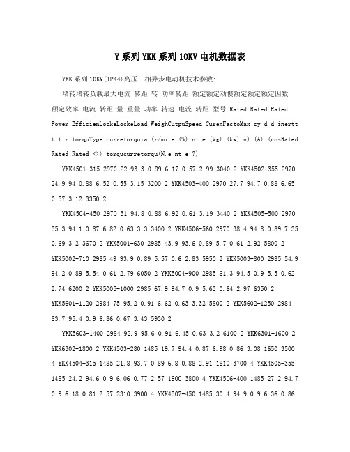
Y系列YKK系列10KV电机数据表YKK系列10KV(IP44)高压三相异步电动机技术参数:堵转堵转负载最大电流转距转功率转距额定额定动惯额定额定额定因数额定效率电流转距量重量功率转速电流转距型号 Rated Rated Rated Power EfficienLockeLockeLoad WeighCutpuSpeed CurenFactoMax cy d d inertt t t r torquType curretorquia (r/mi e (%) nt e (kg) (kw) n) (A) (cosRated Rated Rated Φ) torqucurretorqu(N.e nt e ?)YKK4501-315 2970 22 93.3 0.89 6.17 0.57 2.99 3040 2 YKK4502-355 2970 24.9 94 0.88 6.52 0.55 3.15 3200 2 YKK4503-400 2970 27.7 94.7 0.88 6.65 0.57 3.12 3350 2YKK4504-450 2970 31 94.8 0.88 6.92 0.61 3.19 3440 2 YKK4505-500 2970 35.3 94.1 0.87 6.82 0.63 3.3 3400 2 YKK4506-560 2970 38.4 94.8 0.89 7.35 0.69 3.2 3670 2 YKK5001-630 2985 43.9 93.6 0.89 5.7 0.61 2.92 5800 2 YKK5002-710 2985 49 93.9 0.89 5.57 0.6 2.83 5950 2 YKK5003-800 2985 54.9 94.2 0.89 5.54 0.61 2.79 6050 2 YKK5004-900 2985 61.3 94.5 0.9 5.5 0.62 2.74 6200 2 YKK5005-1000 2985 67.9 94.7 0.9 5.63 0.64 2.97 6350 2YKK5601-1120 2984 75 95.2 0.91 6.62 0.63 3.32 5800 2 YKK5602-1250 2984 83.7 95.4 0.9 6.86 0.67 3.43 5930 2YKK5603-1400 2984 92.9 95.6 0.91 6.45 0.63 3.2 6100 2 YKK6301-1600 2 YKK6302-1800 2 YKK4503-280 1485 19.7 94.4 0.87 6.98 0.86 3.08 1650 3500 4 YKK4504-315 1485 21.8 93.7 0.89 6.8 0.88 2.91 1810 3700 4 YKK4505-355 1485 24.2 94.6 0.9 6.06 0.77 2.57 1900 3800 4 YKK4506-400 1485 27.2 94.7 0.9 6.18 0.81 2.57 2310 3900 4 YKK4507-450 1485 30.4 94.9 0.9 6.36 0.862.59 2540 4000 4 YKK4508-500 1485 33.8 94.8 0.95.73 0.78 2.33 2750 4000 4 YKK4509-560 1485 38.6 94.3 0.88 7.22 1.06 2.87 2870 4000 4 YKK5001-630 1480 43.4 94.9 0.886.81 0.85 2.86 3240 5400 4 YKK5002-710 1480 48.8 95.1 0.88 7 0.91 2.88 3140 5550 4 YKK5003-800 1480 54.5 95.3 0.89 6.65 0.87 2.69 3170 5560 4 YKK5004-900 1480 60.9 95.4 0.9 6.28 0.82 2.52 3210 5670 4 YKK560-4 1000 1492 68.1 95.3 0.89 5.84 0.68 2.3 3840 6750 YKK5601-1120 1492 75.9 95.8 0.89 5.74 0.69 2.23 3880 6740 4 YKK5602-1250 1492 84.6 95.9 0.89 6.04 0.76 2.29 3940 6910 4 YKK5603-1400 1492 94.6 95.9 0.89 6.43 0.85 2.38 4120 7170 4 YKK6301-1600 1492 10.35 95.60.907 6.5 0.6 0.8 5830 7810 4 YKK6302-1800 1492 115.5 95.8 0.915 6.5 0.61.8 6240 8950 4 YKK4502-250 980 18.7 93.8 0.82 5.74 0.762.68 6310 3200 6 YKK4503-280 980 20.7 93.3 0.84 5.76 0.79 2.61 7020 35006 YKK4504-315 980 23.1 93.4 0.84 5.48 0.74 2.48 7300 3600 6 YKK4505-355 980 26 93.7 0.84 5.64 0.78 2.53 7540 3700 6 YKK4506-400 980 29 94 0.85 5.97 0.87 2.59 7710 3900 6 YKK5001-450 985 32.2 94 0.86 5.57 0.81 2.67 8560 5250 6 YKK5002-500 985 35.4 94.2 0.87 5.47 0.81 2.59 9100 5350 6 YKK5003-560 985 39.7 94.4 0.86 5.59 0.84 2.63 10010 5400 6 YKK5004-630 985 44.3 94.5 0.87 5.42 0.82 2.52 12200 5570 6 YKK5005-710 985 44.9 94.6 0.87 5.52 0.86 2.54 12750 5820 6 YKK5601-800 994 56.3 94.8 0.87 6.24 0.9 2.69 25120 6300 6 YKK5602-900 994 62.8 94.9 0.87 6.26 0.92 2.65 34600 6500 6 YKK5603-1000 994 69.1 95 0.88 6.3 0.95 2.61 36250 6800 6 YKK5604-1120 994 77.7 95.1 0.88 6.66 1.04 2.72 37450 7050 6 YKK6301-1250 994 85 95.75 0.88 6.5 0.8 2.17 54600 8860 6 YKK6302-1400 994 95.2 95.86 0.884 6.5 0.8 2.2 61250 9510 6 YKK6303-1600 994 105 95.91 0.887 6.5 0.8 2.2351300 10000 6 YKK4501-11056220 744 17.1 92.3 0.806 5.3 0.91 2.55 3750 8 0YKK4502-11540250 744 18.9 93.1 0.814 6 0.95 2.56 4040 8 0YKK5002-280 745 22 92.8 0.79 5.96 0.93 2.8 31500 5200 8 YKK5003-315 745 25.1 91.8 0.79 5.93 0.94 2.79 31850 5200 8 YKK5004-355 745 27.7 93.2 0.79 5.87 0.93 2.68 32010 5260 8 YKK5005-400 745 30.8 93.3 0.8 5.73 0.92 2.56 32080 54008 YKK5006-450 745 34.2 93.8 0.81 5.6 0.91 2.45 32120 5500 8 YKK5007-500 745 37.9 93.8 0.81 5.64 0.93 2.43 33000 5600 8 YKK5601-560 745 41.1 94.7 0.83 5.42 0.76 2.45 37430 5250 8 YKK5602-630 745 46 94.8 0.84 5.29 0.74 2.37 45860 6420 8 YKK5603-710 745 51.7 94.8 0.84 5.39 0.77 2.38 45910 6460 8 YKK5604-800 745 58.1 94.9 0.84 5.51 0.81 2.38 47560 6720 8 YKK6301-900 744 65.3 95.15 0.841 6 0.7 1.8 74850 8560 8 YKK6302-1000 744 72.5 95.23 0.843 6 0.7 1.8 83450 9230 8 YKK6303-1120 744 81.1 95.4 0.845 6 0.7 1.8 87650 9580 8 YKK5002-250 594 20.7 92.2 0.76 4.98 1.19 2.73 3750 5400 10 YKK5003-280 594 22.6 92.2 0.77 4.55 1.06 2.44 3880 5400 10 YKK5004-315 594 26.2 92.7 0.75 4.49 1.22 2.68 3930 5480 10 YKK5005-355 594 29.3 92.8 0.75 4.91 1.23 2.63 4110 5600 10 YKK5601-400 595 30.9 93.3 0.8 5.48 0.98 2.7 44230 6250 10 YKK5602-450 595 34.1 93.6 0.81 5.26 0.93 2.55 45610 6450 10 YKK5603-500 595 37.9 93.8 0.81 5.33 0.96 2.57 46560 6580 10 YKK5604-560 595 42.7 94.2 0.8 5.87 1.11 2.82 49820 7010 10YKK6301-630 596 48.3 94.1 0.8 6 0.6 1.8 10560 8850 10 YKK6302-710 596 55.1 94.23 0.801 6 0.6 1.8 11350 9240 10 YKK5303-800 596 60.5 94.310.805 6 0.6 1.8 13210 9560 10 YKK5304-900 596 67.2 94.45 0.812 6 0.6 1.8 14230 987010 YKK5601-280 496 24.3 91.9 0.725 5.05 0.99 2.92 7450 6510 12YKK5602-315 496 27.3 92.1 0.723 5.11 1.01 2.97 7650 6710 12 YKK5603-355 496 30.1 92.43 0.738 4.94 0.97 2.77 8430 6730 12 YKK5604-400 496 34.2 92.5 0.729 5.08 1.02 2.87 9010 6920 12 YKK5605-450 496 38 92.8 0.7374.97 0.98 2.77 10650 7170 12 YKK6301-500 496 41.8 92.85 0.734 6 0.7 1.8 11450 8160 12 YKK6302-560 496 45.7 93.35 0.741 6 0.7 1.8 12100 8530 12 YKK6303-630 496 52.4 93.41 0.746 6 0.7 1.8 14750 8950 12 YKK6304-710 496 58.3 93.68 0.748 6 0.7 1.8 15980 9680 12Y系列电机技术参数说明型号额定电流额定转速效率功率因数堵转转矩堵转电流最大转矩η IN nN (cosφ) --------- --------- ---------Type (A) (r/min) (%) 额定转矩额定电流额定转矩Tst/TN Ist/IN Tm/TN同步转速 Synchronous Speed 3000转/分 r/minY90S-2-1.5 3.3 2840 79.7 0.86 2.3 5.5 2.5 Y90L-2-2.2 4.7 2840 81.9 0.87 2.6 6.0 2.5 Y100L-2-3 6.1 2880 83.9 0.88 2.7 6.9 3.2 Y112M-2-4 8.0 2895 85.0 0.89 2.3 6.6 3.2 Y132S1-2-5.5 10.8 2915 85.3 0.91 2.0 6.8 3.0 Y132S2-2-7.5 14.3 2910 86.5 0.92 2.0 6.7 2.9 Y160M1-2-11 21.3 2935 87.4 0.90 2.0 6.6 3.0 Y160M2-2-15 28.3 2935 88.5 0.91 2.0 6.5 2.8 Y160L-2-18.5 34.3 2935 89.4 0.91 2.1 6.7 2.8 Y180M-2-22 41.8 2940 88.7 0.90 2.0 6.3 3.3 Y200L1-2-30 56.5 2955 89.3 0.90 2.0 6.1 3.2 Y200L2-2-37 68.8 2955 90.1 0.90 2.1 6.1 3.1 Y225M-2-45 83.7 2970 90.9 0.90 2.1 6.2 3.22.0 Y250M-2-55 102.8 2970 90.9 0.89 5.93.0 Y280S-2-75 139.2 2975 90.7 0.90 2.2 6.1 3.1 Y280M-2-90 165.8 2975 91.4 0.90 2.3 6.4 3.2 Y315S-2-110 200 2980 93.0 0.90 1.8 7 2.2 Y315M-2-132 237 2980 94.0 0.90 1.8 7 2.2 Y315L1-2-160 286 2980 94.5 0.90 1.8 7 2.2 Y315L2-2-200 356 2980 94.5 0.90 1.8 7 2.2同步转速 Synchronous Speed 1500转/分 r/minY90S-4-1.1 2.7 1400 78.4 0.79 2.7 5.1 2.5 Y90L-4-1.5 3.6 1400 79.5 0.81 2.7 5.1 2.4 Y100L1-4-2.2 4.9 1425 82.1 0.83 2.5 5.7 2.8 Y100L2-4-3 6.6 1430 83.8 0.82 3.1 6.4 3.1Y112M-4-4 8.6 1440 85.5 0.83 3.1 6.8 3.1 Y132S-4-5.5 11.3 1450 86.9 0.85 2.2 6.3 2.7 Y132M-4-7.5 15.0 1450 88.0 0.86 2.4 6.8 2.7 Y160M-4-11 22.1 1460 88.8 0.85 2.2 6.2 2.5 Y160L-4-15 29.9 1460 89.7 0.86 2.3 6.4 2.4 Y180M-4-18.5 36.0 1470 89.9 0.87 2.3 6.8 3.3 Y180L-4-22 42.3 1470 90.5 0.87 2.4 6.8 3.3 Y200L-4-30 56.9 1475 91.3 0.88 2.2 6.5 3.1 Y225S-4-37 69.4 1480 91.8 0.88 2.0 5.2 2.8 Y225M-4-45 83.4 1480 92.1 0.89 2.0 6.0 2.7 Y250M-4-55 101.7 1480 92.4 0.89 2.3 6.4 2.7 Y280S-4-75 137.6 1485 92.7 0.89 2.0 6.1 2.7 Y280M-4-90 163.7 1485 93.3 0.89 2.3 6.6 2.9Y315S-4-110 201 1480 93.5 0.89 1.8 7 2.2 Y315M-4-132 241 1490 93.5 0.89 1.8 7 2.2 Y315L1-4-160 291 1490 94.0 0.89 1.8 7 2.2 Y315L2-4-200 354 1490 95.0 0.89 1.8 7 2.2同步转速 Synchronous Speed 1000转/分 r/minY90S-6-0.75 2.1 920 74.2 0.72 2.4 4.0 2.7 Y90L-6-1.1 3.0 920 74.50.75 2.3 3.7 2.4 Y100L-6-1.5 3.8 940 79.2 0.75 2.6 4.9 2.1 Y112M-6-2.2 5.4 945 81.4 0.75 2.6 5.0 2.6 Y132S-6-3 7.0 960 83.9 0.78 2.4 6.0 2.6Y132M1-6-4 9.1 960 85.0 0.78 2.4 6.1 2.6 Y132M2-6-5.5 12.0 960 86.2 0.80 2.3 5.9 2.3 Y160M-6-7.5 16.4 970 87.8 0.79 2.4 5.8 2.3 Y160L-6-11 23.7 970 88.9 0.79 2.4 5.8 2.3 Y180L-6-15 31.0 975 89.4 0.82 2.6 6.2 2.9Y200L1-6-18.5 37.5 980 89.6 0.84 2.5 6.4 2.7 Y200L2-6-22 44.0 980 90.1 0.84 2.4 6.3 2.7 Y225M-6-30 58.0 985 91.5 0.86 2.1 5.9 2.2 Y250M-6-37 69.3 985 91.7 0.89 2.2 6.2 2.4Y280S-6-45 84.2 985 92.0 0.88 2.1 6.0 3.3 Y280M-6-55 102 985 92.50.89 2.1 5.9 2.3 Y315S-6-75 141 990 93.0 0.87 1.6 6.5 2.0 Y315M-6-90 168 990 93.5 0.87 1.6 6.5 2.0 Y315L1-6-110 204 990 94.0 0.87 1.6 6.5 2.0Y315L2-6-132 245 990 94.0 0.87 1.6 6.5 2.0同步转速 Synchronous Speed 750转/分 r/minY132S-8-2.2 5.6 710 81.2 0.74 2.0 4.4 2.6 Y132M-8-3 7.3 710 82.70.75 2.0 4.5 2.5 Y160M1-8-4 9.5 715 85.3 0.75 2.1 5.0 2.6 Y160M2-8-5.5 12.7 715 86.2 0.76 2.1 5.0 2.6 Y160L-8-7.5 17.0 715 86.9 0.77 2.0 4.9 2.5 Y180L-8-11 24.4 730 88.4 0.78 2.2 5.8 2.8 Y200L-8-15 32.9 730 88.9 0.78 2.2 5.5 2.8 Y225S-8-18.5 39.7 735 90.7 0.78 2.2 5.2 2.5 Y225M-8-22 46.4 735 91.0 0.79 2.2 5.1 2.4 Y250M-8-30 61.6 735 91.6 0.81 2.3 5.5 2.4 Y280S-8-37 76.1 740 92.2 0.80 2.3 5.6 2.4 Y280M-8-45 90.8 740 92.7 0.81 2.2 5.4 2.3 Y315S-8-55 111 740 92.0 0.82 1.6 6.5 2.0 Y315M-8-75 150 740 92.5 0.82 1.6 6.5 2.0 Y315L1-8-90 179 740 93.0 0.82 1.6 6.5 2.0 Y315L2-8-110 219 740 93.0 0.82 1.6 6.5 2.0。
Tygon绞纺管说明书
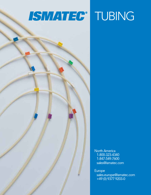
TUBINGNorth America1-800-323-43401-847-549-7600***************** Europe************************ +49 (0) 9377 9203-02NorthAmerica:*****************|1-800-323-4340|1-847-549-7600Europe:************************|+49(0)93779203-014-035, REV. CNEW!NEW!TYGON ® TYGONISMAPRENETYGON SILICONE* Permeability Coefficient = Amount of Gas (cm 3) x tubing wall thickness (cm)x 10-10Surface Area of tubing ID (cm 3) x time (sec) x pressure drop across tubing wall (cm Hg)Peristaltic Pumps & TubingIsmatec peristaltic pumps require peristaltic tubing to operate. Flow rate of a given fluid through a peristaltic tubing pump depends on two variables:1. T he speed of the pump, measured in revolutions per minute (rpm)2. T he volume held with the internal diameter (ID) of the selected tubingVariable Speed Pump Flow RatesFor a variable speed pump, the flow rate of a channel can be changedby varying the pump rpm, or by using tubing with different IDs, or a combination of both.3NorthAmerica:*****************|1-800-323-4340|1-847-549-7600Europe:************************|+49(0)93779203-014-035, REV. CTYGON TYGON TYGONNORPRENE ®Ordering your Pump & TubingFollow these steps to complete your Ismatec ® peristaltic tubing pump order:1. S elect the pump for your application based on the requirements of your fluid delivery task(s): a. Level of accuracyb. Fluid streams (# of channels)c. Flow rate range(s)d. Need for constant flow, discrete dispensing, or bothe. Need for variable speedf.Need for automation/programmability2. N ote whether the selected pump requires 2-stop, 3-stop, or standard tubing.3. R eview the tubing properties tables on pages 2-3 and select the tubing material best suited for your application.4. R eview the page that contains information and options for the tubing material you have selected.5. I dentify the correct part number for the tubing you need, based upon two factors: a) if your pump requires tubing with stops or not, and if so how many; and b) the correct inner diameter and wall thickness for the model pump you are using.6. I f required, order extension tubing that corresponds as closely as possible to the tubing material and ID of your 2-stop or 3-stop tubing.4NorthAmerica:*****************|1-800-323-4340|1-847-549-7600Europe:************************|+49(0)93779203-014-035, REV. C T ygon E-LFL TubingXX DEHP FreeXX Longest service life of anyclear Tygon tubing materialXX Excellent choice wheretransparency and goodchemical resistance is neededTygon S3 E-LFL tubing is availablein a broad range of sizes for usethroughout our pump productline. Its good chemical resistancecoupled with its durability makes it an excellent choice in those applications where longer-life tubing is desired (i.e., where tubes are not disposed of frequently).In many cases, this tubing can withstand system pressures that are in excess of most peristaltic pumps’ abilities, providing built-in safety precautions for your system flow path.Choose tubing without stops for use with most single-channel pumps. (Note: Ensure the wall thickness of the tubing you have selected matches the requirements for the pump you are using.) Choose the 2-stop or 3-stop tubing for use with the versions of our pumps that incorporate cassettes into the pumphead design.SPECIFICATIONS & DETAILST ygon®LMT-55 Tubing XX DEHP FreeXX The Tygon blend of choicefor general laboratoryapplicationsTygon LMT-55 offers an all-around, inexpensive option forgeneral laboratory applications.Featuring transparent walls andlow gas permeability — andwith many different sizes fromwhich to choose — this tubing material option is the option of choice for many less-critical applications. To determine the expected flow rates related to the tubing inner diameters, see the technical specifications for your pump model in your pump’s operating manual.Please Note: The low overall lifetime of this material will require tubing to replaced more frequently. For a longer life version of Tygon LMT-55, consider Tygon S3 E-LFL.SPECIFICATIONS & DETAILS NEW!NEW!5NorthAmerica:*****************|1-800-323-4340|1-847-549-7600Europe:************************|+49(0)93779203-014-035, REV. CIsmaprene Tubing (PharMed ®)X X Excellent chemical resistancefor traditional peristalticpump tubingX X Offers FDA and USP Class VI certificationPharMed Ismaprene tubing has long been the tubing of choice for many demanding applications where other polymer blends have been unsuitable for use.With strong chemical resistance, excellent lifetime, and low gas permeability — coupled with industry-standard certifications — PharMed tubing is offered in options for standard pumps as well as for pumps requiring 2-stop and 3-stop tubing. Special versions are available with welded stops for applications where repeated autoclaving must take place.SPECIFICATIONS & DETAILST ygon ® 3350 SI TubingX X Platinum-cured silicone tubing X X Features ultra-smooth inner-bore X X Biocompatible for lifescience applicationsTygon 3350 SI tubing is a special silicone-based tubing that undergoes a special treatment with platinum to ensure a very smooth internal surface. This surfacefeature helps improve the material’s use with biological applications where solid material may be present. Additionally, the material exhibits a low-level of protein-binding as well as being non-toxic, helping to makethis material the top choice for many life science applications.SPECIFICATIONS & DETAILS6NorthAmerica:*****************|1-800-323-4340|1-847-549-7600Europe:************************|+49(0)93779203-014-035, REV. C T ygon® 2001 Tubing for Aggressive MediaXX High chemical resistance forbroad application useXX Options available forsingle and multi-channelpump systemsXX U ltra-pure tubing forperistaltic pumpsTygon 2001 tubing features all of thebenefits of most Tygon blends —including wall transparency andFDA approval. Added to this is strong chemical resistance for many solutions (excluding hydrocarbons), making Tygon 2001 a material of choice for many demanding applications where other blends may not be suitable.Options are available in both Standard Tubing, up to 0.626” (15.9 mm) and Stopper Tubing up to 0.109” (2.79 mm).SPECIFICATIONS & DETAILSSilicone Peroxide Tubing XX Non-toxic material great forbiological applications XX Soft and translucent for applications requiringvisual checksSPECIFICATIONS & DETAILS7NorthAmerica:*****************|1-800-323-4340|1-847-549-7600Europe:************************|+49(0)93779203-014-035, REV. CT ygon ® MHLL TubingX X Dual-layered tubing material X X Pairs chemical resistance andlong-lifeTygon MHLL is a unique tubing material, comprised of an inner layer of Tygon MH and an outer layer of PharMed ®. This combination helps ensure excellent chemical resistance (except for hydrocarbons andstrong ketones) as well as long service life. Available as Stopper Tubing for use with MS/CA cassettes.Additionally, this material offers both FDA approval as well as USP Class VI approval, making it a material of choice for more demanding life-science applications.SPECIFICATIONS & DETAILST ygon HC F-4040-A TubingX X Specially formulatedfor hydrocarbon-based applications X X Features low gas permeability and good pressure resistanceTygon F-4040-A tubing has been specially-formulated for use in petroleum (and similar) applications where other Tygonblends cannot be used successfully. The material offers some of the lowest gas permeability rates for atmospheric gases of all the Tygon blends, making it ideal for use in those applications where sensitivity to gas permeation is high or where vacuum may be applied. In addition to being suitable for hydrocarbon-based applications, this material can also be used successfully with low-concentration acidic solutions as well as mineral salt solutions.Yellow-tinted, the material offers some degree of translucency, however, it is not as transparent as many other Tygon blends.SPECIFICATIONS & DETAILS8NorthAmerica:*****************|1-800-323-4340|1-847-549-7600Europe:************************|+49(0)93779203-014-035, REV. C Fluran®F-5500-A TubingXX S pecially-formulated elastomerfor use with strong acidic andbasic solutionsXX Very low gas permeabilityFluran tubing has been speciallyformulated for use in applicationswhere strong acidic solutions orstrong basic solutions are being used.The material’s very low gas per-meability also makes this the choice material for applications where fluids can be transferred without being contaminated by atmospheric gases. Additionally, the low gas permeability and relative strength of this material make it a material of choice in vacuum based applications.SPECIFICATIONS & DETAILSNorprene® A-60-G T ubingXX Long-life tubing with strongchemical resistanceXX Excellent option forindustrial applicationsNorprene tubing is an excellentalternative to traditional rubbertubing in industrial applicationswhere good chemical resistanceis paired with a desire for longerservice life.This tubing material offers additional benefits, including low gas permeability and broad temperature range compatibility. Combined, this material’s features help make this tubing the tubing of choice in many applications.SPECIFICATIONS & DETAILS9NorthAmerica:*****************|1-800-323-4340|1-847-549-7600Europe:************************|+49(0)93779203-014-035, REV. CPart No.Part No.Part No.Part No.Part No.Part No.Part No.Extension TubingThe next seven pages contain product numbers for ordering Standard, 2-Stop, 3-Stop, and Extension tubing in each material offered.NEW!10NorthAmerica:*****************|1-800-323-4340|1-847-549-7600Europe:************************|+49(0)93779203-014-035, REV. C2-Stop T ubingPart No.Part No.Part No.Part No.Part No.Part No.NEW!NEW!11NorthAmerica:*****************|1-800-323-4340|1-847-549-7600Europe:************************|+49(0)93779203-014-035, REV. CPart No.Part No.Part No.Part No.Part No.12NorthAmerica:*****************|1-800-323-4340|1-847-549-7600Europe:************************|+49(0)93779203-014-035, REV. C3-Stop TubingNEW!Part No.Part No.Part No.Part No.Part No.Part No.13NorthAmerica:*****************|1-800-323-4340|1-847-549-7600Europe:************************|+49(0)93779203-014-035, REV. CPart No.Part No.Part No.Part No.Part No.14NorthAmerica:*****************|1-800-323-4340|1-847-549-7600Europe:************************|+49(0)93779203-0 14-035, REV. CStandard TubingNEW!ISMAPRENE1.6 mm wall thickness (1/16”) Standard Tubing Part No.Part No.Part No.Part No.Part No.Part No.15NorthAmerica:*****************|1-800-323-4340|1-847-549-7600Europe:************************|+49(0)93779203-014-035, REV. CPart No.Part No.Part No.Part No.Part No. 1.6 mm wall thickness (1/16”) Standard TubingFor ordering and technical support, please contact:North America *****************|1-800-323-4340|1-847-549-7600Europe ************************|+49(0)93779203-0Learn more about theIsmatec ® product line by visiting: 。
立象科技O4系列打印机使用手册说明书
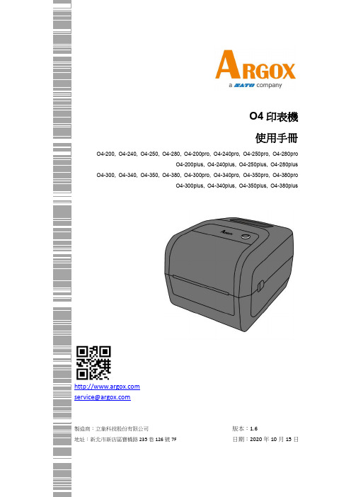
O4印表機使用手冊O4-200, O4-240, O4-250, O4-280, O4-200pro, O4-240pro, O4-250pro, O4-280proO4-200plus, O4-240plus, O4-250plus, O4-280plus O4-300, O4-340, O4-350, O4-380, O4-300pro, O4-340pro, O4-350pro, O4-380proO4-300plus, O4-340plus, O4-350plus, O4-380plus*****************製造商:立象科技股份有限公司地址:新北市新店區寶橋路235巷126號7F 版本:1.6日期:2020年10月15日修訂記錄專屬聲明本手冊包含立象科技股份有限公司擁有之專屬資訊。
這些資訊僅供負責操作及維護手冊中所述之設備的相關人士參考及使用。
未經過立象科技股份有限公司書面同意,不論任何情況下均不得對此類專屬資訊進行使用、再製,或揭露給任何第三方。
產品改良持續改良產品是立象科技股份有限公司奉行的原則之一。
所有的規格及符號得隨時變更,恕不事先通知。
賠償聲明立象科技股份有限公司已採取必要步驟,確保本公司所發行之設計規格及手冊的正確性;但這些出版品仍可能存在錯誤。
立象科技股份有限公司將保留修改任何此類錯誤之權利,並聲明免除任何相關的賠償責任。
不論任何情況下,立象科技股份有限公司或與隨附產品(包含軟硬體) 的製作、生產或運送程序相關之人士,均不對因使用本產品,或因無法使用本產品所導致的任何損害(包括但不限於商機損失、業務中斷、商業資訊損失或,其他金錢損失所造成的任何損害) 負賠償責任,不論立象科技股份有限公司是否已被告知此等情事。
注意:未經相容性主管機關明確許可的情況下,對設備進行的任何變更或修改都可能導致使用者喪失操作本設備之權利。
警告使用者:這是甲類的資訊產品,在居住的環境中使用時,可能會造成射頻干擾,在這種情況下,使用者會被要求採取某些適當的對策。
molex 0740760005 VHDM 背板连接器和电缆组件用户手册说明书
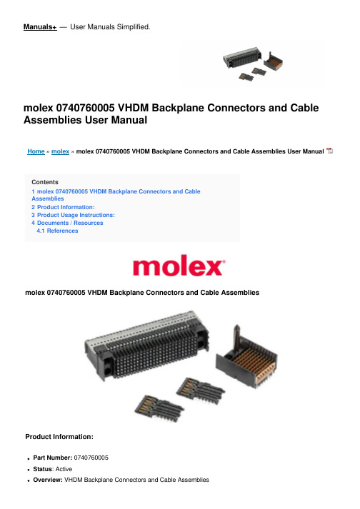
Manuals+— User Manuals Simplified.molex 0740760005 VHDM Backplane Connectors and Cable Assemblies User ManualHome » molex » molex 0740760005 VHDM Backplane Connectors and Cable Assemblies User ManualContents1 molex 0740760005 VHDM Backplane Connectors and CableAssemblies2 Product Information:3 Product Usage Instructions:4 Documents / Resources4.1 Referencesmolex 0740760005 VHDM Backplane Connectors and Cable AssembliesProduct Information:Part Number: 0740760005Status: ActiveOverview: VHDM Backplane Connectors and Cable AssembliesDescription: VHDM-HSD Free-Standing Guide PinDocuments:Drawing (PDF)Product Specification PS-74031-999-001 (PDF)RoHS Certificate of Compliance (PDF)General:Product Family: Backplane ConnectorsSeries: 74076Application: BackplaneApplication Tooling: NoneData Rate: N/AOverview Product Name: VHDM Backplane Connectors and Cable Assemblies VHDM, VHDM-HSDTaxonomy: N/AUPC: 883906461713Physical:Circuits (Loaded): 0Circuits (maximum): 0Durability (mating cycles max): 200Guide to Mating Part: YesKeying to Mating Part: NoneNet Weight: 2.608/gNumber of Columns: N/ANumber of Pairs: N/ANumber of Rows: 0Orientation: N/APC Tail Length: N/APCB Locator: N/APCB Retention: YesPCB Thickness – Recommended: 1.80mm, 4.00mmPackaging Type: BagPitch – Mating Interface: N/APitch – Termination Interface: N/ASurface Mount Compatible (SMC): NoTemperature Range – Operating: N/AElectrical:Current – Maximum per Contact: N/AShielded: NoVoltage – Maximum: N/AMaterial Info:Reference – Drawing Numbers:Product Specification: PS-74031-999-001Sales Drawing: SD-74076-002-001, SD-74076-005-001Compliance:EU ELV: Not RelevantEU RoHS: CompliantChina RoHS: CompliantREACH SVHC: Not Contained per D(2022)9120-DC (17 Jan 2023)Halogen-Free Status:Low-HalogenFor more information, please visit Contact USChina ROHS: Green ImageELV: Not RelevantRoHS Phthalates : Not Relevant,Search Parts in this Series74076 SeriesProduct Usage Instructions:To use the VHDM Backplane Connectors and Cable Assemblies VHDM-HSD Free-Standing Guide Pin, follow these instructions:1. Ensure that the product is compatible with your specific application. Refer to the product specificationdocument (PS-74031-999-001) for detailed information.2. If necessary, use appropriate application tooling for installation. However, note that no specific applicationtooling is required for this product.3. Take into account the physical specifications of the product, such as the number of circuits, durability (matingcycles), guide to mating part, and PCB retention.4. Consider the electrical specifications, including the maximum current per contact, shielded or non-shieldedconfiguration, and maximum voltage.5. Refer to the provided drawing numbers (Product Specification, Sales Drawing) for additional reference andinformation.6. Ensure compliance with relevant regulations such as EU RoHS, China RoHS, and REACH SVHC. Verify thehalogen-free status of the product.If you have any further questions or need more information, please visit the official website of the manufacturer, Molex, at . Alternatively, you can contact their support team directly.This document was generated on 03/24/2023PLEASE CHECK FOR LATEST PART INFORMATIONDownloaded from .Documents / Resourcesmolex 0740760005 VHDM Backplane Connectors and Cable Assemblies [pdf] User Manual0740760005 VHDM Backplane Connectors and Cable Assemblies, 0740760005, VHDMBackplane Connectors and Cable Assemblies, VHDM Backplane Connectors, Backplane Connectors, ConnectorsReferencesCreating Connections for Life | MolexManuals+,。
