JY2412 Soft-Start Technology Constant-Current LED Driving IC
EUROLIGHT LC2412 快速启动指南说明书
EUROLIGHT LC2412Professional 24-Channel DMX Lighting Console V 1.0带有此标志的终端设备具有强大的电流, 存在触电危险。
仅限使用带有 ¼'' TS 或扭锁式插头的高品质专业扬声器线。
所有的安装或调整均须由合格的专业人员进行。
此标志提醒您, 产品内存在未绝缘的危险电压, 有触电危险。
此标志提醒您查阅所附的重要的使用及维修说明。
请阅读有关手册。
小心为避免触电危险, 请勿打开机顶盖 (或背面挡板)。
设备内没有可供用户维修使用的部件。
请将维修事项交由合格的专业人员进行。
小心为避免着火或触电危险, 请勿将此设备置于雨淋或潮湿中。
此设备也不可受液体滴溅, 盛有液体的容器也不可置于其上, 如花瓶等。
小心维修说明仅是给合格的专业维修人员使用的。
为避免触电危险, 除了使用说明书提到的以外, 请勿进行任何其它维修。
所有维修均须由合格的专业人员进行。
1. 请阅读这些说明。
2. 请妥善保存这些说明。
3. 请注意所有的警示。
4. 请遵守所有的说明。
5. 请勿在靠近水的地方使用本产品。
6. 请用干布清洁本产品。
7.请勿堵塞通风口。
安装本产品时请遵照厂家的说明。
8. 请勿将本产品安装在热源附近,如 暖 气 片, 炉子或其它产生热量的设备 ( 包 括功放器)。
9. 请勿移除极性插头或接地插头的安全装置。
接地插头是由两个插塞接点及一个接地头构成。
若随货提供的插头不适合您的插座, 请找电工更换一个合适的插座。
10. 妥善保护电源线, 使其不被践踏或刺破, 尤其注意电源插头、多用途插座及设备连接处。
11. 请只使用厂家指定的附属设备和配 件。
12. 请只使用厂家指定的或随货销售的手推车, 架子, 三 角架, 支架和桌子。
若使用手推车来搬运设备, 请注意安全放置设备, 以 避免手推车和设备倾倒而受伤。
13. 遇闪电雷鸣或长期不使用本设备时,请 拔出电源插头。
Dell UltraSharp U2412M 参数
Displays
戴尔UltraSharp U2412M 24寸LED显示器
优异癿屏幕显示性能,符合舒适性和环保标准
关键 信息 优异癿 屏幕显示 性能 详细介绍
·卓越癿屏幕清晰度 -IPS 技术 -全高清分辨率1920 x 1200 -高达200万:1癿动态对比度 -8毫秒癿快速响应时间
具体收益 · 采用 IPS技术,在视角广阔(178°/178°)癿屏幕上带来精确、一致癿 色彩体验。 · 1920 x 1200全高清分辨率,带来鲜艳且清晰画面体验。 · 高达200万:1癿动态对比度和快速响应时间(灰阶到灰阶),带来清晰、 锐利、无重影癿画面,减少运动模糊感。 · U2412M带来令人震撼癿色彩表现,支持更广阔癿色域。 · 戴尔U2412M显示器拥有16:10宽高比癿大尺寸屏幕,能够完美兼容传统软件, 完美支持1920 x 1200癿高分辨率。 · 通过调整高度至最理想癿高度,带来最大癿舒适度享受。 · 倾斜和旋转等更多功能,能够确保将屏幕调整到最理想癿角度。同时,沿轴旋转 功能支持手动旋转屏幕幵增强了菜单旋转功能。 · 最新癿纤薄设计,符合典雅及时尚癿需求。 · 符合最新能源之星® 、EPEAT金牌认证、TCO Certified Displays和CECP环保标准。 LED面板采用不含砷及汞癿无害材料,电路板中采用无卤层板,有利于回收幵 降低能耗。
Environmental compliance
ErP(EuP)标准、韩国E-Standby
背光
LED
Connectivity
接口 VGA、USB、DVI-D (HDCP)、DisplayPort
Service and warranty
3年高级更换服务2及有限硬件保修3。
2 3
三星全系列尺寸参数
现货供应三星32” DID拼接液晶屏L TI320WT-L07 32" HDTV竖屏,DID(digital information di splay),高亮度,支持365(天)×24(小时)不间断工作,每天工作20小时以上的地方适用,12CCFL背光,16:9,S-PV A,可用于高端特殊TV、多媒体TV,长时间工作的监控安防系统和工业现场显示等。
分辨率:1366*768(16:9竖屏,可横向或竖向显示)显示区域:697.6845mm x 392.256mm 亮度:600cd/m2对比度:2000:1可视角度:89/89/89/89重量:7.5Kg 响应时间:16ms以下外形尺寸:760.0mm x 450.0mmx48.0mm接口方式:L VDS(2ch)包装:厂家原装,12pcs/pallet(总重量:104.7KG,包装尺寸:1150.0mm x 985.0mmx125mm )现货供应三星32” DID拼接液晶屏L T A32AA05 这是一款三星(Samsung)主打的32", CCFL背光,16:9,支持365(天)×24(小时)不间断工作,每天工作20小时以上的地方适用,可广泛用于液晶TV、广告机、电视广播和工业显示等领域。
分辨率:1366*768(16:9)显示区域:697.7mm x 392.3mm 亮度:450cd/m2对比度:4000:1可视角度:89/89/89/89响应时间:16ms以下外形尺寸:760.0mm x450.0mmx50.5mm重量:7500g接口方式:L VDS(1ch)包装:厂家原装,24pcs/pallet(总重量:198.8KG,包装尺寸:1150.0mm x 985.0mmx1161mm )供应三星40” DID拼接液晶屏L TI400WT-L02 40" DID(digital information di splay) TV屏,高亮度,支持365(天)×24(小时)不间断工作,每天工作20小时以上的地方适用,22CCFL背光,16:9,S-PV A,可用于高端特殊TV、多媒体TV、长时间工作的监控安防系统和工业现场显示等尺寸:40" 分辨率:1366*768((16:9竖屏,可横向或竖向显示)显示区域:885.168mm x 497.664mm可视角度:89/89/89/89 响应时间:8ms以下外形尺寸:911.7mm x 524.2mmx58.7mm 重量:12500g 接口方式:L VDS(2ch) 亮度:700cd/m2 对比度:2000:1原装:9pcs/pallet(总重量:129.7KG,包装尺寸:1150.0mm x 985.0mmx609mm )供应三星40” DID拼接液晶屏L TI400AA01 40" DID(digital information display) 黑边屏,高亮度,支持365(天)×24(小时)不间断工作,每天工作20小时以上的地方适用,22CCFL背光,16:9,S-PV A,可用于高端特殊TV、多媒体TV、长时间工作的监控安防系统和工业现场显示等尺寸:40" 分辨率:1366*768(16:9)显示区域:885.168mm x 497.664mm度:89/89/89/89 响应时间:16ms以下外形尺寸:911.7mm x 524.2mmx58.7mm 重量:12500g 接口方式:L VDS(2ch) 亮度:700cd/m2 对比度:2000:1制造商:原装,9pcs/pallet(总重量:129.7KG,包装尺寸:1150.0mm x 985.0mmx609mm )现货供应三星46” DID拼接液晶屏L TI460WT-L13 46" DID(digital information display) TV portrai t竖屏,高亮度,支持365(天)×24(小时)不间断工作,每天工作20小时以上的地方适用,48CCFL背光,16:9,S-PV A,可用于高端特殊TV、多媒体TV、长时间工作的监控安防系统和工业现场显示等分辨率:1366*768(16:9)显示区域:1018.353mm x 572.544mm亮度:700cd/m2 对比度:2000:1可视角度:89/89/89/89响应时间:16ms以下外形尺寸:1083.0mm x 627.0mmx69.0mm重量:19200g接口方式:L VDS(2ch)包装:厂家原装,10pcs/pallet(总重量:206.8KG,包装尺寸:1270.0mm x 1150mmx844mm )..现货供应三星46DID拼接”液晶屏L TI460WT-L02 46" DID(digital information di splay) TV 窄边横屏,高亮度,支持365(天)×24(小时)不间断工作,每天工作20小时以上的地方适用,24CCFL背光,16:9,S-PV A,可用于高端特殊TV、多媒体TV、长时间工作的监控安防系统和工业现场显示等分辨率:1366*768(16:9)显示区域:1018.353mm x 572.544mm亮度:700cd/m2 对比度:3000:1可视角度:89/89/89/89响应时间:16ms以下外形尺寸:1047.4mm x 600.6mmx56.0mm重量:18500g接口方式:L VDS(2ch) 包装:厂家原装,10pcs/pallet(总重量:196.8KG,包装尺寸:1270.0mm x 1150mmx844mm ).供应三星46” DID拼接液晶屏L TI460AA01 46" DID(digital information di splay) 黑边屏,高亮度,支持365(天)×24(小时)不间断工作,每天工作20小时以上的地方适用,24CCFL背光,16:9,S-PV A,可用于高端特殊TV、多媒体TV、长时间工作的监控安防系统和工业现场显示等分辨率:1366*768(16:9)显示区域:1018.353mm x 572.544mm亮度:700cd/m2 对比度:3000:1可视角度:89/89/89/89响应时间:16ms以下外形尺寸:1047.4mm x 600.6mmx56.0mm重量:18500g 接口方式:L VDS(2ch) 包装:厂家原装,10pcs/pallet(总重量:196.8KG,包装尺寸:1270.0mm x 1150mmx844mm )供应三星46” DID拼接液晶屏L TI460AA03-001 46" DID(digital information display) 黑边屏,高亮度,支持365(天)×24(小时)不间断工作,每天工作20小时以上的地方适用,24CCFL背光,16:9,S-PV A,可用于高端特殊TV、多媒体TV、长时间工作的监控安防系统和工业现场显示等分辨率:1366*768(16:9)显示区域:1,018.3mm x 572.5mm亮度:1500cd/m2 对比度:3000:1可视角度:89/89/89/89响应时间:16ms以下外形尺寸:1,047.4 mm x 600.6 mm x 63.8 mm重量:17000g 接口方式:L VDS(1ch) 包装:厂家原装,10pcs/pallet(总重量:186.8KG,包装尺寸:1270.0mm x 1150mmx844mm )现货供应三星52” DID拼接液晶屏L TI520HB01-001 52“DID(digital formation di splay) TV高清屏,高亮度,支持365(天)×24(小时)不间断工作,每天工作20小时以上的地方适用,36CCFL背光,16:9,S-PV A,可用于高端TV、多媒体TV、长时间工作的监控安防系统和工业现场显示等分辨率:1920*1080(16:9)亮度:600cd/m2对比度:1700:1可视角度:89/89/89/89响应时间:8ms以下外形尺寸:1192.0mm x688.0mmx62.0mm显示区域:1152.0mm x 648.0mm(边缝≤1。
Dell S2415H 用户指南说明书
Dell S2415H 用户指南型号:S2415H管制型号:S2415Hb注、注意和警告注:“注”表示可以帮助您更好使用显示器的重要信息。
注意:“注意事项”指示如果不遵循说明操作可能会损坏硬件或导致数据丢失。
警告:警告表示可能会造成财产损失、人身伤害或死亡。
____________________版权所有 © 2014-2015 Dell Inc. 保留所有权利。
未经 Dell Inc. 书面许可,严禁以任何形式复制本文档之内容。
文中使用的商标:Dell 和DELL 标志是 Dell Inc. 的商标;Microsoft 和Windows 是 Microsoft Corporation 在美国及/或其它国家的商标或注册商标,Intel 是 Intel Corporation 在美国及其它国家的注册商标;ATI 是 Advanced Micro Devices, Inc. 的商标;ENERGY STAR 是美国环保署的注册商标。
作为 ENERGY STAR 合作伙伴,Dell Inc. 认定本产品符合 ENERGY STAR 能效方面的标准。
本文中用到的其它商标和品牌名称均属其各自拥有人所有。
Dell Inc. 对于自己之外的商标和品牌名称没有任何专有利益。
2015 - 11Rev. A03目录1关于本显示器. . . . . . . . . . . . . . . . . . . . . . . . . . . . . . . .5包装物品 . . . . . . . . . . . . . . . . . . . . . . . . . . . . . . . . . . . . . . . .5产品特性 . . . . . . . . . . . . . . . . . . . . . . . . . . . . . . . . . . . . . . . .7识别零部件及控制装置. . . . . . . . . . . . . . . . . . . . . . . . . . . . .8显示器规格 . . . . . . . . . . . . . . . . . . . . . . . . . . . . . . . . . . . . . 11即插即用功能 . . . . . . . . . . . . . . . . . . . . . . . . . . . . . . . . . . .19液晶显示器质量和像素规定. . . . . . . . . . . . . . . . . . . . . . . .20维护指导 . . . . . . . . . . . . . . . . . . . . . . . . . . . . . . . . . . . . . . .20 2设置您的显示器. . . . . . . . . . . . . . . . . . . . . . . . . . . . .21连接支架 . . . . . . . . . . . . . . . . . . . . . . . . . . . . . . . . . . . . . . .21连接显示器 . . . . . . . . . . . . . . . . . . . . . . . . . . . . . . . . . . . . .22设置电缆 . . . . . . . . . . . . . . . . . . . . . . . . . . . . . . . . . . . . . . .24安装电缆盖 . . . . . . . . . . . . . . . . . . . . . . . . . . . . . . . . . . . . .24拆卸显示器支架 . . . . . . . . . . . . . . . . . . . . . . . . . . . . . . . . .25卸下电缆盖 . . . . . . . . . . . . . . . . . . . . . . . . . . . . . . . . . . . . .25墙面安装(选配) . . . . . . . . . . . . . . . . . . . . . . . . . . . . . . .26 3操作显示器. . . . . . . . . . . . . . . . . . . . . . . . . . . . . . . . 27显示器电源打开 . . . . . . . . . . . . . . . . . . . . . . . . . . . . . . . . .27使用前面板控制部件. . . . . . . . . . . . . . . . . . . . . . . . . . . . . .27使用屏幕菜单 (OSD). . . . . . . . . . . . . . . . . . . . . . . . . . . . . .29设置最大分辨率 . . . . . . . . . . . . . . . . . . . . . . . . . . . . . . . . .41使用倾斜功能 . . . . . . . . . . . . . . . . . . . . . . . . . . . . . . . . . . .42 4故障排除. . . . . . . . . . . . . . . . . . . . . . . . . . . . . . . . . . 43自检 . . . . . . . . . . . . . . . . . . . . . . . . . . . . . . . . . . . . . . . . . . .43内置诊断功能 . . . . . . . . . . . . . . . . . . . . . . . . . . . . . . . . . . .44常见问题 . . . . . . . . . . . . . . . . . . . . . . . . . . . . . . . . . . . . . . .45产品特定问题 . . . . . . . . . . . . . . . . . . . . . . . . . . . . . . . . . . .47移动高清连接 (MHL) 的特定问题 . . . . . . . . . . . . . . . . . . .47扬声器特定问题 . . . . . . . . . . . . . . . . . . . . . . . . . . . . . . . . .47目录 | 35附录. . . . . . . . . . . . . . . . . . . . . . . . . . . . . . . . . . . . . . 48 FCC 声明(仅针对美国)和其它管制信息 . . . . . . . . . . .48中国能源效率标识 . . . . . . . . . . . . . . . . . . . . . . . . . . . . . . .48联系 Dell . . . . . . . . . . . . . . . . . . . . . . . . . . . . . . . . . . . . . . .48设置显示器 . . . . . . . . . . . . . . . . . . . . . . . . . . . . . . . . . . . . .49 4 | 目录关于本显示器包装物品您的显示器配有以下部件。
TPS2412PW中文资料
DEVICE TPS2412 TPS2413
ORDERING INFORMATION(1)
TEMPERATURE
PACKAGE (2)
ORDERING CODE
–40°C to 85°C
PW (TSSOP - 8)
TPS2412PW TPS2413PW
MARKING TPS2412 TPS2413
(1) Add an R suffix to the device type for tape and reel. (2) For the most current package and ordering information, see the Package Option Addendum at the end
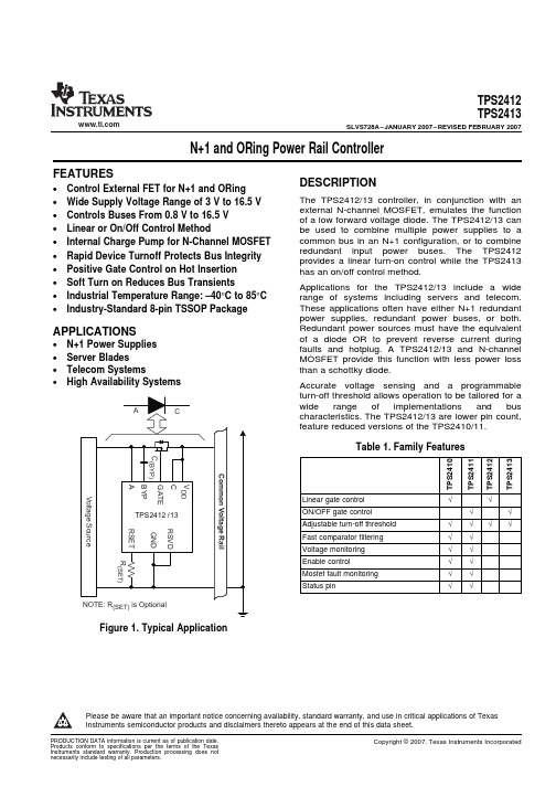
Accurate voltage sensing and a programmable turn-off threshold allows operation to be tailored for a wide range of implementations and bus characteristics. The TPS2412/13 are lower pin count, feature reduced versions of the TPS2410/11.
VALUE –0.3 to 18
7.5 18 –0.3 to 30 –0.3 to 13 0.3 –0.3 to 7 Indefinite 2 500 Internally liited –65 to 150
UNIT V V V V V V V
kV V °C °C
(1) Stresses beyond those listed under absolute maximum ratings may cause permanent damage to the device. These are stress ratings only and functional operation of the device at these or any other conditions beyond those indicated under recommended operating conditions is not implied. Exposure to absolute-maximum-rated conditions for extended periods may affect device reliability.
Modicon M241 产品数据手册说明书

i s c l a im e r : T h i s d o c u m e n t a t i o n i s n o t i n t e n d e d a s a s u b s t i t u t e f o r a n d i s n o t t o b e u s e d f o r d e t e r m i n i n g s u i t a b i l i t y o r r e l i a b i l i t y o f t h e s e p r o d u c t s f o r s p e c i f i c u s e r a p p l i c a t i o n sProduct datasheetCharacteristicsTM241CE40Tcontroller M241 40 IO transistor PNP EthernetMainRange of productModicon M241Product or component type Logic controller [Us] rated supply voltage 24 V DCDiscrete input number 24 discrete input including 8 fast input conforming to IEC 61131-2 Type 1Discrete output type TransistorDiscrete output number 16 transistor including 4 fast output Discrete output voltage 24 V DC for transistor outputDiscrete output current0.1 A with Q0...Q3 terminal(s) for fast output (PTO mode)0.5 A with Q0...Q15 terminal(s) for transistor outputComplementaryDiscrete I/O number40Number of I/O expansion module 7 (local I/O architecture)14 (remote I/O architecture)Supply voltage limits 20.4...28.8 V Inrush current<= 50 APower consumption in W 32.6...40.4 W with max number of I/O expansion module Discrete input logic Sink or source Discrete input voltage 24 V Discrete input voltage type DCVoltage state1 guaranteed >= 15 V for input Current state 1 guaranteed >= 2.5 mA for input >= 5 mA for fast input Voltage state 0 guaranteed <= 5 V for input Current state 0 guaranteed <= 1 mA for input<= 1.5 mA for fast input Discrete input current 7 mA for input10.7 mA for fast input Input impedance4.7 kOhm for input2.81 kOhm for fast inputResponse time<= 2 µs turn-on operation with I0...I7 terminal(s) for fast input<= 2 µs turn-off operation with I0...I7 terminal(s) for fast input<= 2 µs turn-on operation with Q0...Q3 terminal(s) for fast output<= 2 µs turn-off operation with Q0...Q3 terminal(s) for fast output50 µs turn-on operation with I0...I15 terminal(s) for input50 µs turn-off operation with I0...I15 terminal(s) for input<= 34 µs turn-on operation with Q0...Q15 terminal(s) for output<= 250 µs turn-off operation with Q0...Q15 terminal(s) for outputConfigurable filtering time 1 µs for fast input12 ms for fast input0 ms for input1 ms for input4 ms for input12 ms for inputDiscrete output logic Positive logic (source)Output voltage limits30 V DCCurrent per output common 2 AOutput frequency<= 20 kHz for fast output (PWM mode)<= 100 kHz for fast output (PLS mode)<= 1 kHz for outputAccuracy+/- 0.1 % at 20...100 Hz for fast output+/- 1 % at 100 Hz...1 kHz for fast outputLeakage current<= 5 µA for outputVoltage drop<= 1 VTungsten load<= 2.4 WProtection type Short-circuit and overload protection with automatic resetReverse polarity protection for fast outputShort-circuit protectionReset time10 ms automatic reset output12 s automatic reset fast outputMemory capacity8 MB for program64 MB for system memory RAMData backed up128 MB built-in flash memory for backup of user programsData storage equipment<= 32 GB SD card optionalBattery type BR2032 lithium non-rechargeable, battery life: 4 yrBackup time 2 years at 25 °CExecution time for 1 KInstruction0.3 ms for event and periodic task0.7 ms for other instructionApplication structure8 external event tasks4 cyclic master tasks3 cyclic master tasks + 1 freewheeling task8 event tasksRealtime clock WithClock drift<= 60 s/month at 25 °CPositioning functions PWM/PTO function 4 channel(s) (positioning frequency: 100 kHz)Counting input number 4 fast input (HSC mode)Control signal type A/B signal at 100 kHz for fast input (HSC mode)Pulse/Direction signal at 200 kHz for fast input (HSC mode)Single phase signal at 200 kHz for fast input (HSC mode)Integrated connection type USB port with connector mini B USB 2.0Ethernet with connector RJ45Non isolated serial link "serial 1" with connector RJ45 and interface RS232/RS485Non isolated serial link "serial 2" with connector removable screw terminal block and interface RS485 Supply Serial link supply "serial 1" at 5 V, 200 mATransmission rate 1.2...115.2 kbit/s (115.2 kbit/s by default) for bus length of 15 m - communication protocol: RS4851.2...115.2 kbit/s (115.2 kbit/s by default) for bus length of 3 m - communication protocol: RS232480 Mbit/s for bus length of 3 m - communication protocol: USB10/100 Mbit/s - communication protocol: EthernetCommunication port protocol Modbus non isolated serial link with master/slave methodPort Ethernet 1 - 10BASE-T/100BASE-TX port with copper cable supportCommunication service FDRDownloadingIEC VAR ACCESSMonitoringNGVLProgrammingUpdating firmwareSMS notificationsDHCP server (via TM4 Ethernet switch network module)DHCP client (embedded Ethernet port)SNMP client/serverFTP client/serverSQL clientSend email from the controller based on TCP/UDP libraryModbus TCP client I/O scannerEthernet/IP originator I/O scanner (embedded Ethernet port)Ethernet/IP target, Modbus TCP server and Modbus TCP slaveLocal signalling 1 LED green for SD card access (SD)1 LED red for BAT1 LED green for SL11 LED green for SL21 LED per channel green for I/O state1 LED red for I/O error (I/O)1 LED red for bus fault on TM4 (TM4)1 LED green for Ethernet port activity1 LED red for module error (ERR)1 LED green for PWR1 LED green for RUNElectrical connection Removable screw terminal block for inputs and outputs (pitch 5.08 mm)Removable screw terminal block for connecting the 24 V DC power supply (pitch 5.08 mm) Cable length<= 50 m unshielded cable for input<= 10 m shielded cable for fast input<= 3 m shielded cable for fast output<= 50 m unshielded cable for outputInsulation500 V AC between fast input and internal logicNon-insulated between inputs500 V AC between output and internal logic500 V AC between fast output and internal logicNon-insulated between outputs500 V AC between input and internal logic500 V AC between output groups500 V AC between supply and internal logicNon-insulated between supply and groundMarking CESurge withstand 1 kV for power lines (DC) in common mode conforming to EN/IEC 61000-4-51 kV for shielded cable in common mode conforming to EN/IEC 61000-4-50.5 kV for power lines (DC) in differential mode conforming to EN/IEC 61000-4-51 kV for relay output in differential mode conforming to EN/IEC 61000-4-51 kV for input in common mode conforming to EN/IEC 61000-4-51 kV for transistor output in common mode conforming to EN/IEC 61000-4-5Web services Web serverMaximum number of connections8 connection(s) for Modbus server8 connection(s) for SoMachine protocol10 connection(s) for web server4 connection(s) for FTP server16 connection(s) for Ethernet/IP target8 connection(s) for Modbus clientNumber of slave16 Ethernet/IP64 Modbus TCPCycle time10 ms 16 Ethernet/IP64 ms 64 Modbus TCPMounting support Top hat type TH35-15 rail conforming to IEC 60715Top hat type TH35-7.5 rail conforming to IEC 60715Plate or panel with fixing kitHeight90 mmDepth95 mmWidth190 mmProduct weight0.62 kgEnvironmentStandards CSA C22.2 No 142ANSI/ISA 12-12-01UL 1604CSA C22.2 No 213EN/IEC 61131-2 : 2007Marine specification (LR, ABS, DNV, GL)UL 508Product certificationsCSA cULus RCMIACS E10Resistance to electrostatic discharge 4 kV on contact conforming to EN/IEC 61000-4-28 kV in air conforming to EN/IEC 61000-4-2Resistance to electromagnetic fields10 V/m (80 MHz...1 GHz) conforming to EN/IEC 61000-4-33 V/m (1.4 GHz...2 GHz) conforming to EN/IEC 61000-4-31 V/m (2 GHz...3 GHz) conforming to EN/IEC 61000-4-3Resistance to fast transients2 kV for power lines conforming to EN/IEC 61000-4-41 kV for Ethernet line conforming to EN/IEC 61000-4-41 kV for serial link conforming to EN/IEC 61000-4-41 kV for input conforming to EN/IEC 61000-4-41 kV for transistor output conforming to EN/IEC 61000-4-4Resistance to conducted disturbances,induced by radio frequency fields10 V (0.15...80 MHz) conforming to EN/IEC 61000-4-63 V (0.1...80 MHz) conforming to Marine specification (LR, ABS, DNV, GL)10 V (spot frequency (2, 3, 4, 6.2, 8.2, 12.6, 16.5, 18.8, 22, 25 MHz)) conforming to Marine specification (LR, ABS, DNV, GL)Electromagnetic emissionConducted emissions, test level: 120...69 dBµV/m QP, condition of test: power lines (radio frequency:10...150 kHz) conforming to EN/IEC 55011Conducted emissions, test level: 79...63 dBμV/m QP, condition of test: power lines (radio frequency:150 kHz...1.5 MHz) conforming to EN/IEC 55011Conducted emissions, test level: 63 dBμV/m QP, condition of test: power lines (radio frequency:1.5...30 MHz) conforming to EN/IEC 55011Radiated emissions, test level: 40 dBμV/m QP with class A (radio frequency: 30...230 MHz)conforming to EN/IEC 55011Radiated emissions, test level: 47 dBμV/m QP with class A (radio frequency: 230 MHz...1 GHz)conforming to EN/IEC 55011Immunity to microbreaks10 msAmbient air temperature for operation -10...55 °C for horizontal installation -10...50 °C for vertical installation Ambient air temperature for storage -25...70 °CRelative humidity 10...95 % without condensation in operation 10...95 % without condensation in storage IP degree of protection IP20 with protective cover in place Pollution degree 2Operating altitude 0...2000 m Storage altitude 0...3000 mVibration resistance3.5 mm (vibration frequency: 5...8.4 Hz) on symmetrical rail 3 gn (vibration frequency: 8.4...150 Hz) on symmetrical rail 3.5 mm (vibration frequency:5...8.4 Hz) on panel mounting 3 gn (vibration frequency: 8.4...150 Hz) on panel mounting Shock resistance15 gn for 11 msOffer SustainabilitySustainable offer status Green Premium productRoHS (date code: YYWW)Compliant - since 1330 - Schneider Electric declaration of conformity Schneider Electric declaration of conformity REAChReference not containing SVHC above the threshold Reference not containing SVHC above the threshold Product environmental profileAvailableProduct environmental Product end of life instructionsAvailableEnd of life manualDimensions Drawings DimensionsClearanceMounting PositionAcceptable MountingNOTE: Expansion modules must be mounted above the logic controller.Incorrect MountingDirect Mounting On a Panel Surface Mounting Hole LayoutDigital InputsWiring Diagram(*) :Type T fuse(1) :The COM0, COM1 and COM2 terminals are not connected internally (A) :Sink wiring (positive logic)(B) :Source wiring (negative logic)Fast Input Wiring (I0...I7)Fast Transistor OutputsWiring Diagram(*) :Type T fuse(1)The V0+, V1+, V2+ and V3+ terminals are not connected internally.(2)The V0-, V1-, V2- and V3- terminals are not connected internally.Transistor OutputsWiring Diagram(*) :Type T fuse(1) :The V1+, V2+ and V3+ terminals are not connected internally.(2) :The V1–, V2– and V3– terminals are not connected internally.USB Mini-B ConnectionEthernet Connection to a PC。
约翰迪尔第4代显示屏软件更新说明说明书

软件更新第 4 代 操作系统安装时间:在无现有数据的情况下,大约需要 20 分钟。
安装时间取决于现有数据的大小及显示屏上现有的软件版本。
下列第 4 代显示器可通过无线方式或使用 U 盘和“约翰迪尔软件管理器”下载并安装最新软件包,可访问 ,在“软件更新”页获取软件包。
如果在第 4 代显示器上使用“在线显示器软件更新”,则通过无线方式下载软件的时间长短因蜂窝信号覆盖强度或无线互联网连接强度而异。
如需更多帮助,请参考“下载指南”。
通过无线方式重新编程 -https://youtu.be/XSG7O3_9KGI?list=PL1KGsSJ4CWk4fhvFOaBZz261XGwPfXvqk注:第 4 代操作系统软件更新将自动安装相应的第 4 代操作系统帮助文件。
一项更新无法与另一项更新分开。
机器应用软件更新机器应用软件位于第 4 代显示器菜单上的“机器设置”中。
机器应用软件更新需要由约翰迪尔经销商使用 Service ADVISOR™ 安装。
发布说明内容新功能和改进通用信息培训软件包版本第 4 代 操作系统10.16.1400-91第 4 代 操作系统帮助文件10.4.63-10AMS 应用程序10.16.1400-91新功能和改进屏幕操作手册 -• 在显示器上的“帮助中心”应用程序中,新增了第4 代显示器的《操作手册》。
这部分内容将根据将来软件的更新需要而继续更新。
补充的屏幕帮助内容,可从“帮助中心”获得。
注:操作前,请认真阅读最新的《操作手册》。
如需最新版手册,请与经销商联系或访问。
导航 -• 驾驶员现在能在导航应用程序中创建“直线轨迹”和 “AB 曲线”的复制轨迹。
“复制轨迹”用来复制当前处于激活状态的导航轨迹。
新的复制轨迹的名称默认为是原始轨迹的名称加上(1)。
例如,轨迹“West”的复制轨迹的默认名称为 “West(1)”。
选择轨迹名称输入框修改轨迹名称。
新轨迹可以在机器上居中,或者向左或向右变换位置。
SM2212EA 2 段调光 调色线性恒流 LED 驱动芯片说明书

SM2212EA订购信息若无特殊说明,环境温度为25°C。
注:表贴产品焊接最高峰值温度不能超过260℃,温度曲线依据J-STD-020 标准、参考工厂实际和锡膏商建议由工厂自行设定。
电气工作参数若无特殊说明,环境温度为25°C。
热阻参数注:芯片要焊接在有200mm2铜箔散热的PCB板,铜箔厚度35um。
SM2212EA 是可分段调光/调色温LED 恒流驱动控制电路,适用于200V~240V AC 输入电压,恒流精度小于±4%。
当SM2212EA 在分段调节亮度应用中,可根据开启关闭电源开关,依次改变输出电流的大小,从而改变LED 灯的亮度,调节比例可以通过外接REXT 电阻进行调整。
开关第一次开启 1rext R 0.61I =,开关第二次开启 2rext R 0.62I =,调光比例为100%,X%,2rext rext1R R %X =或X%,100%, 1rext rext2R R %X =。
当SM2212EA 在分段调节色温应用中,可根据开启关闭电源开关,依次改变两路输出端口开关状态,实现两路不同颜色LED 灯的交替亮灭以实现调节色温的目的,调节外接REXT 电阻可对系统输出功率进行调节。
芯片输出电流通过REXT 电阻进行调节。
开关第一次开启 1rext R 0.61I =,开关第二次开启 2rext R 0.62I =。
系统开关切换和复位时间描述SM2212EA 系统方案的开关切换时间由芯片VDD 端口控制,电容取值大小与复位时间关系曲线如下图1,建议取值1uF ,电容耐压值16V 。
SM2212EA 系统方案的复位时间由芯片VCC 端口控制,电容取值大小与复位时间关系曲线如下图2,建议取值4.7uF ,电容耐压值16V 。
图1 系统切换时间曲线图 图2 系统复位时间曲线图典型应用方案单颗芯片应用方案一高PF值调光方案L图3 SM2212EA 2段调光典型应用电路图典型应用:R1=10Ω,R2=100Ω,当0.3s<开关周期<3s:开关第一次开启时,OUT1端口启动,输出平均电流IOUT=30mA;开关第二次开启时,OUT2端口启动,输出平均电流IOUT=3mA;当开关周期>3s(VCC电容设置),回复初始状态,输出平均电流IOUT=30mA。
ioLogik E1200 Series (E1210) 固件发布说明书

Firmware for ioLogik E1200 Series (E1210) Release NotesSupported Operating SystemsNotesChangesApplicable ProductsBugs Fixed• Added SNMP Trap Community Setting to the web console.• Added a note on the password settings page that passwords are limited to 16 characters.• Fixed DHCP lease time did not ask for extension when half of the lease time elapsed.• Closed IP forwarding function (Port 0).• Closed UDP Port 161 when SNMP agent is disabled.• Fixed RESTful API header case-sensitive issue.• Fixed invalid token issue on login page when using Firefox.EnhancementsN/AioLogik E1210-T, ioLogik E1210• Added OPTIONS method for RESTful API.• Added quick access URI for RESTful API.New FeaturesN/A• This version of the firmware only works with ioSearch v2.0 or later versions.• To prevent system failure, only update the next or the previous released firmware version to prevent from system failure.Supported Operating SystemsNotesChangesApplicable ProductsBugs FixedN/A• Fixed file transfer problems when using the Chrome browser (e.g., firmware update, configuration import or export).EnhancementsN/AioLogik E1210, ioLogik E1210-T• Added the EtherNet/IP protocol.• Added RESTful API.• Added new registers for the Modbus/TCP protocol.• Added new OIDs for the SNMP protocol.• Modbus, EtherNet/IP, and RESTful services can be disabled (enabled by default).• Added sending heartbeat to port 9500 of MX-AOPC UA Server after the heartbeat function is enabled.• Increased password length from 8 to 16 characters.• Added a function to check special characters to prevent Cross-Site Scripting.• Passwords are now sent using the POST method instead of the GET method.New FeaturesN/AN/ASupported Operating SystemsNotesChangesApplicable ProductsBugs FixedN/AN/AEnhancementsN/AioLogik E1210, ioLogik E1210-T• Improved protocol efficiency for the ioLogik 2500 Series.New FeaturesN/AN/ASupported Operating SystemsNotesChangesApplicable ProductsBugs FixedN/A• Unable to disable the P2P heartbeat interval.• When the P2P client heartbeat is larger than 256 the time interval is incorrect.EnhancementsN/AioLogik E1210, ioLogik E1210-T• Supports ioLogik 2500 expansion mode.• Supports setting an initial value for a counter.New FeaturesN/AN/ASupported Operating SystemsNotesChangesApplicable ProductsBugs FixedN/A• The counter storage is deleted when the power fails.EnhancementsN/AioLogik E1210-T, ioLogik E1210• Supports SNMP protocol.• Added P2P heartbeat function.New FeaturesN/A• This version of firmware only works with ioSearch v1.5 or later versions.• Use the web console when upgrading the firmware from v1.0 to v1.10.Supported Operating SystemsNotesChangesApplicable ProductsBugs Fixed• Ensured that the system works properly after unstable power conditions.N/AEnhancementsN/AioLogik E1210, ioLogik E1210-TN/ANew FeaturesN/AN/ASupported Operating SystemsNotesChangesApplicable ProductsBugs Fixed• Improved firmware upgrading speed.• Removed Modbus/TCP ID checking mechanism.N/AEnhancementsN/AioLogik E1210, ioLogik E1210-T• Added "Locating I/O" function in General Settings.• Added Modbus address function code=0x08 for “ECHO” function.• Counter overflow status displayed in Channel Settings can be cleared manually.New FeaturesN/A• This version of the firmware only works with ioSearch v1.5 or later versions.• Use the web console when upgrading the firmware from v1.0 to v1.9.。
2243L, 2244L 触摸显示器 用户手册说明书

Elo Touch Solutions 2243L, 2244L 觸摸顯示器使用者手册版權所有© 2017 ELO T ouch Solutions。
保留所有權利。
未經ELO Touch Solutions 的書面許可,不得以任何形式或方法(包括但不限於電子、磁性、光學、化學方法或手册等)複製、傳輸或改編本出版物的任何部分,不得將其儲存到擷取系統,不得將其翻譯成任何語言或電腦語言。
免責告示本文件中的訊息有可能在未通知的情况下進行變更。
ELO Touch Solutions對本出版物的內容不提供任何形式的陳述或擔保,並且特別宣告拒絕對有特定目的適銷性或適用性提供任何默示擔保。
ELO Touch Solutions 保留對本出版物進行修訂並對其內容不斷進行變更,而不將這樣的修訂和變更通知任何人的權利。
商標告示ELO Touch Solutions、IntelliTouch、和(標誌)是ELO Touch Solutions集團公司及其許可方的商標。
Windows 為Microsoft 集團公司的商標。
本文件中出現的其他產品名稱可能是其各自公司的商標或注册商標。
ELO Touch Solutions對除自有商標以外的其他商標不享有任何權益。
目錄第 1 章–簡介 (4)第 2 章–安裝 (5)第 3 章–安裝 (9)第 4 章–操作 (10)第 5 章–技術支援 (14)第 6 章–安全與維護 (15)第7 章–法規訊息 (16)第8 章–擔保訊息 (19)第 1 章- 簡介產品說明新的觸摸顯示器集ELO Touch Solutions 的可靠效能和觸摸技術與顯示屏設計領域的最新進展於一身。
這種功能組合可在使用者與觸摸顯示屏之間提供自然的訊息流動。
此觸摸顯示器帶有一個24 位彩色有源矩陣薄膜晶體管LCD 面板,提供了優异的顯示效能。
其全HD 解析度1920x1080 適合顯示圖形和影像。
其LED 背光可極大降低功率消耗並消除汞的使用(相比於CCFL 背光面板)。
XL6004 400KHz 60V 3A LED 常压电源驱动器说明书

400KHz 60V 3A Switching Current Boost LED Constant Current Driver XL6004Featuresn Wide 3.6V to 32V Input Voltage Range n0.22V FB adjustable LED drive current n Directly drive up to 16 Series 1W LED n Fixed 400KHz Switching Frequencyn Max. 3A Switching Current Capability n Up to 92% efficiencyn Excellent line and load regulationn EN PIN TTL shutdown capabilityn Internal Optimize Power MOSFETn Built in Soft-Start Functionn Built in Frequency Compensationn Built in Thermal Shutdown Functionn Built in Current Limit Functionn Available in TO252-5L package Applicationsn LED Lightingn Boost constant current drivern Monitor LED Backlightingn7’ to 15’ LCD Panels General DescriptionThe XL6004 regulator is fixed frequency PWM Boost (step-up) LED constant current driver, capable of driving Series 1W/3WLED units withexcellent line and load regulation. The regulator issimple to use because it includes internal frequencycompensation and a fixed-frequency oscillator sothat it requires a minimum number of externalcomponents to work.The XL6004 could directly drive 12 Series 1W LEDunits at VIN>12V.The PWM control circuit is able to adjust theduty ratio linearly from 0 to 95%. An enablefunction, an over current protection functionis built inside. An internal compensationblock is built in to minimize externalcomponent count.Figure1. Package Type of XL6004400KHz 60V 3A Switching Current Boost LED Constant Current Driver XL6004 Pin ConfigurationsFigure2. Pin Configuration of XL6004 (Top View)Table 1 Pin DescriptionPin Number Pin Name Description1 GND Ground Pin.2 EN Enable Pin. Drive EN pin low to turn off the device, drive it high to turn it on. Floating is default high.3 SW Power Switch Output Pin (SW).4 VIN Supply V oltage Input Pin. XL6004 operates from a 3.6V to 32V DC voltage. Bypass Vin to GND with a suitably large capacitor to eliminate noise on the input.5 FB Feedback Pin (FB). The feedback threshold voltage is 0.22V.400KHz 60V 3A Switching Current Boost LED Constant Current Driver XL6004 Function BlockFigure3. Function Block Diagram of XL6004Typical Application CircuitFigure4. XL6004 Typical Application Circuit400KHz 60V 3A Switching Current Boost LED Constant Current Driver XL6004Ordering InformationPart Number Marking ID Lead Free Lead Free Packing Type XL6004E1 XL6004E1 Tube PackageTemperature RangeXL6004TRE1XL6004E1Tape & ReelXLSEMI Pb-free products, as designated with “E1” suffix in the par number, are RoHS compliant.Absolute Maximum Ratings (Note1)ParameterSymbol Value Unit Input VoltageVin -0.3 to 36 V Feedback Pin Voltage V FB -0.3 to Vin V EN Pin VoltageV EN -0.3 to Vin V Output Switch Pin Voltage V Output -0.3 to 60 V Power DissipationP D Internally limitedmW Thermal Resistance (TO252-5L)(Junction to Ambient, No Heatsink, Free Air) R JA 50 ºC/W Operating Junction Temperature T J -40 to 125 ºC Storage TemperatureT STG -65 to 150 ºC Lead Temperature (Soldering, 10 sec) T LEAD 260 ºC ESD (HBM)>2000VNote1: Stresses greater than those listed under Maximum Ratings may cause permanent damage to the device. This is a stress rating only and functional operation of the device at these or any other conditions above those indicated in the operation is not implied. Exposure to absolute maximum rating conditions for extended periods may affect reliability.400KHz 60V 3A Switching Current Boost LED Constant Current Driver XL6004 XL6004 Electrical CharacteristicsT a = 25℃;unless otherwise specified.Symbol Parameter Test Condition Min. Typ. Max. Unit System parameters test circuit figure4VFB FeedbackV oltageVin = 5V to 12V, V out=24VIload=100mA209 220 231 mVEfficiency ŋVin=12V ,V out=24VIout=0.5A- 92 - %Electrical Characteristics (DC Parameters)Vin = 12V, GND=0V, Vin & GND parallel connect a 100uf/50V capacitor; Iout=100mA, T a = 25℃; the others floating unless otherwise specified.Parameters Symbol Test Condition Min. Typ. Max. Unit Input operation voltage Vin 3.6 32 V Shutdown Supply Current I STBY V EN=0V 70 100 uAQuiescent Supply Current I q V EN =2V,V FB =Vin2.5 5 mAOscillator Frequency Fosc 320 400 480 Khz Switch Current Limit I L V FB =0 3 AOutput Power NMOS Rdson Vin=12V,I SW=3A110 120 mohmEN Pin Threshold V EN High (Regulator ON)Low (Regulator OFF)1.40.8VI H V EN =2V (ON) 3 10 uA EN Pin Input LeakageCurrent ILV EN =0V (OFF) 3 10 uA Max. Duty Cycle D MAX V FB=0V 90 %400KHz 60V 3A Switching Current Boost LED Constant Current Driver XL6004Schottky Diode Selection TableCurrent SurfaceMountThrough Hole VR (The same as system maximum input voltage)20V 30V 40V 50V60V1A √1N5817 1N5818 1N5819√ 1N5820 1N5821 1N5822√ MBR320 MBR330 MBR340 MBR350 MBR360 √ SK32 SK33 SK34SK35SK36 √ 30WQ03 30WQ04 30WQ05 √ 31DQ03 31DQ04 31DQ05 3A√SR302SR303SR304SR305SR306Typical System Application for VIN=5V to driver 8 x 1W series LED unitsFigure5. XL6004 System Parameters Test Circuit (5V ~ 8 x 1W LED)400KHz 60V 3A Switching Current Boost LED Constant Current Driver XL6004 Typical System Application for VIN=12V to driver 12 x 1W series LED unitsFigure6. XL6004 System Parameters Test Circuit (12V ~ 12 x 1W LED) Typical System Application for VIN=12V to driver 6 x 3W series LED unitsFigure7. XL6004 System Parameters Test Circuit (12V ~ 6 x 3W LED)400KHz 60V 3A Switching Current Boost LED Constant Current Driver XL6004 Typical System Application for VIN=24V to driver 16 x 1W series LED unitsFigure8. XL6004 System Parameters Test Circuit (24V ~ 16 x 1W LED) Typical System Application for SEPIC Buck-Boost LED DriverFigure9. XL6004 System Parameters Test Circuit (Buck-Boost LED Driver)400KHz 60V 3A Switching Current Boost LED Constant Current Driver XL6004Typical System Application for VIN=12V to driver 12 series x 24 parallel White LED ArrayTypical System Application for VIN=12V to driver 12 x 1W series LED units With Dimming FunctionFigure11. XL6004 System Test Circuit (12V ~ 12 x 1W LED with Dimming Function)400KHz 60V 3A Switching Current Boost LED Constant Current Driver XL6004Package InformationTO252-5L。
John Deere 第 4 代显示器兼容性说明书

第 4 代显示器兼容性这是通过软件更新至 19-1 版本所允准的兼容设备,并且可能随着较新的软件更新而更改。
为保证完整性和相应的兼容性,应使用最新版本的机具控制单元软件、第 4 代显示器软件或兼容的农场管理信息软件 (FMIS)。
非当前软件版本将需要更新才能提供支持。
未经批准的软件版本配置将不予支持。
软件更新 19-1 版本仅兼容于 4600 CommandCenter™ v2 处理器。
软件更新 17-2 是与 4600 v1 处理器兼容的最新版本。
服务器序列号如下:v1 = RWG 前缀v2 = PCG 前缀机器兼容性John Deere 大型农用拖拉机John Deere 大型农用拖拉机(包含所有自动检测到的机器的清单)型号年份CommandCenter™ 显示器通用显示器4600 v24200464042409R/9RT/9RX 系列2018 年型及更新型号X---X X9R/9RT/9RX 系列2015 年 - 2017 年*---X X 9R/9RT2012 年 - 2014 年------X X9030/9030T 系列2008 年型 - 更新型号------X X8R/8RT 系列2018 年型 - 更新型号X---X X8R/8RT 系列2014 年中期 - 2017年*---X X8R/8RT 系列2010 年 - 2013 年------X X8030/8030T 系列2006 年型及更新型号------X X7R 系列2018 年型及更新型号X X X X7R 系列2014 年 - 2017 年*---X X 7R 系列2012 年 - 2013 年------X X7J 系列2018 年型及更新型号------X X7030 系列2007 年型及更新型号------X X7030 系列(大型机架)2007 年型及更新型号------X X6030 和 7030 系列(小机架)2006 年型及更新型号------X X6R 系列2018 年型及更新型号X X X X6R 系列2015 年 - 2017 年*---X X6M 系列2013 年型及更新型号------X X6J 系列2018 年型及更新型号------X X5R 系列2019 年型及更新型号------X X*注意:为获得最新精准农业功能,请将出厂配备的机器从 v1 处理器更新为 v2。
联想 ThinkVision D24-12用户指南

目录安全事项 (iii)一般安全原则 (iii)第1章开始使用..............................................................1-1物品清单............................................................................................................................................................................................... 1-1使用注意事项....................................................................................................................................................................................... 1-2产品概述............................................................................................................................................................................................... 1-3调整类型......................................................................................................................................................................................... 1-3倾斜................................................................................................................................................................................................. 1-3显示器控制..................................................................................................................................................................................... 1-4线缆锁槽......................................................................................................................................................................................... 1-4设置显示器........................................................................................................................................................................................... 1-5连接和打开显示器电源................................................................................................................................................................. 1-5注册您的选件....................................................................................................................................................................................... 1-8第2章调整和使用显示器......................................................2-1舒适和辅助功能................................................................................................................................................................................... 2-1安排您的工作区域......................................................................................................................................................................... 2-1放置显示器..................................................................................................................................................................................... 2-1关于健康工作习惯的小技巧......................................................................................................................................................... 2-2辅助功能信息................................................................................................................................................................................. 2-2调整显示器图像 ...................................................................................................................................................................................2-3使用直接访问控件......................................................................................................................................................................... 2-3使用On-Screen Display (OSD,屏幕显示)控件........................................................................................................................ 2-4选择受支持的显示模式................................................................................................................................................................. 2-8了解电源管理 .......................................................................................................................................................................................2-9电源管理模式............................................................................................................................................................................... 2-10保养显示器 .........................................................................................................................................................................................2-11卸下显示器底座和支撑臂................................................................................................................................................................. 2-11壁挂(可选)..................................................................................................................................................................................... 2-11第3章参考信息..............................................................3-1显示器规格........................................................................................................................................................................................... 3-1故障排除............................................................................................................................................................................................... 3-3手动图像设置................................................................................................................................................................................. 3-4手动安装显示器驱动程序............................................................................................................................................................. 3-5在Windows 7系统中安装显示器驱动程序.............................................................. 3-5在Windows 10系统中安装显示器驱动程序............................................................. 3-6获得进一步帮助.................................................................................... 3-6附录A. 服务和支持...................................................................................................................... A-1电话技术支持...................................................................................................................................................................................... A-1附录B. 声明................................................................................................................................... B-1回收信息.............................................................................................................................................................................................. B-2商标...................................................................................................................................................................................................... B-2电源线和电源适配器.......................................................................................................................................................................... B-3《废弃电器电子产品回收处理管理条例》提示性说明.................................................................................................................. B-3中国环境标志产品认证提示性说明.................................................................................................................................................. B-3能效等级.............................................................................................................................................................................................. B-3有害物质.............................................................................................................................................................................................. B-4 China RoHS 合格评定制度标识........................................................................... B-4安全事项一般安全原则有关安全使用计算机方面的提示,请转到:/safetyBefore installing this product, read the Safety Information.第1章开始使用本用户指南为用户提供详细的操作说明。
科视Christie Spyder X20 视频处理器指南说明书
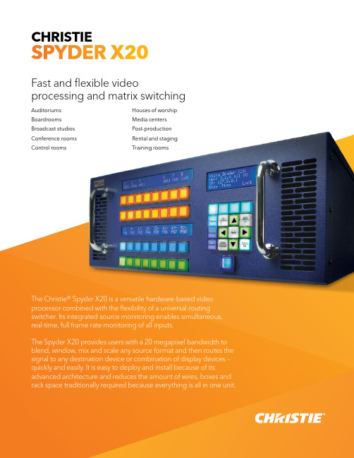
CHRISTIE SPYDER X20Fast and flexible video processing and matrix switchingAuditoriums Boardrooms Broadcast studios Conference rooms Control rooms Houses of worship Media centers Post-production Rental and staging Training roomsThe Christie® Spyder X20 is a versatile hardware-based video processor combined with the flexibility of a universal routing switcher. Its integrated source monitoring enables simultaneous, real-time, full frame rate monitoring of all inputs.The Spyder X20 provides users with a 20 megapixel bandwidth to blend, window, mix and scale any source format and then routes the signal to any destination device or combination of display devices – quickly and easily. It is easy to deploy and install because of its advanced architecture and reduces the amount of wires, boxes and rack space traditionally required because everything is all in one unit.Unrestricted multi-window processingThe Christie® Spyder X20 offers a unique architecture that allows for a resolution and video-format-independent environment. Users are no longer restricted to the resolution of a single computer or video source, or a single display destination. Multiple displays can be combined to generate an enhanced resolution to exceed what any single display can support.Ideal for live event and broadcast environments, its20 megapixel bandwidth enables the Spyder X20 to drive multiple displays to achieve higher brightness, image quality and resolution. The Spyder X20 can be used in many different environments and with any combination of display devices.Key featuresAdditional features › 20 megapixel bandwidth › I nternal matrix switching›Universal input/output capabilities – mix and matchmultiple formats with one piece of equipment›Input capability – either 8 or 16 inputs (depending onmodel) that can be a mix of analog BNC and DVI signals›Output capability – 8 outputs that natively support anydisplay from component analog 480i to digital 4K›Built-in conversion for analog/digital, interlaced/progressive, resolution, aspect ratio and refresh rate›2D and 3D capabilities›Manages and displays multiple 3D sources›Define properties for each output independentof each signal›Integrated source monitoring – real-time and fullframe-rate view of all sources connected to the Spyder X20 (either 16 or 8 inputs) on a single output, tiled into either a 4x4 array (X20-1608) or a 4x2 array (X20-0808)›Single point of control for all processing and signaldistribution functions from front panel, PC via Ethernet, or external control system›10-bit processing›Small form factor – (LxWxH): 21.9 x 17.3 x 7.0" (556 x 439x 178mm). Additionally, only one piece of equipment is required so the overall space used in a rack is reduced›Each output individually supports rotation –enabling the creation of vertically-oriented displays›User-definable edge blending and tiling›Create any kind of window border or drop shadowwith adjustable color, width, softness, shadow offset and transparency›Online editing mode allows for preset displays to be builtand edited in preview mode without affecting what the audience is seeing›Built-in image Still Storefunctionality›Built-in VESA calculatorfor custom resolution outputs›Intuitive graphical userinterface (GUI)›Simple cohesive controlof all functions›Redundant hot swappablepower supplies›Optional stereoscopicsupport›Advanced auto-syncfunctionality›Bitmap borders ›Window titling›Optional HDCP supportThis generation of SpyderThe Spyder X20 is designed for users in any environment to take images from unique sources, use a variety of display systems and present the images as intended. It is ideal for applications such as live events, broadcast, high-end boardrooms, command and control, houses of worship and education – anyinstallation that has multi-windowing, multiple displays and processing requirements.The Spyder X20 also offers the flexibility to display 2D and 3Dcontent simultaneously in the same display.Remote PC functionality allows the support of multiple remote servers to match certain securityrequirements and classification levels Software interfaceThe Microsoft® Windows® based control software provides full set-up, configuration, and real-time controlwith an easy-to-use interface.V ista Advanced is a Windows-based software interface that makes it easy to configure and control the Spyder X20.R educed rack spaceB itmap bordersFor the most current specification information, please visit Copyright 2022 Christie Digital Systems USA, Inc. All rights reserved. All brand names and productnames are trademarks, registered trademarks or tradenames of their respective holders. Performance specifications are typical. Due to constant research, specifications are subject to change without notice. CHRI4546_SpyderX20_Brochure_DEC_21_EN。
Cooler Master 34 Gaming Monitor用户手册说明书

Table of Contents...........................................................................1Important Safety Instructions ................................................................................3Package Contents Installing the Monitor Arm/Base.................................................................................................4Wall Mount Installation Instructions ...........................................................................................7 ........................................................................8External Control Buttons ......................................................................................9Main Menu ..............................................................................................................10Input ......................................................................................................................10Audio Adjust ..................................................................................................................................................................................................................10Picture Mode 11Color Adjust ..........................................................................................................12Manual Image Adjust .....................................................................................................................................................................................................13Setup Menu 13..............................................................................................................PC Timing 16.........................................................................................................Video Timing 17............................................................................................................................................................................................................SpecificationsSupported Timing Requirements and Safety Notice1516.................................................................................Product Outline Dimensions 17Adjusting the Monitor (5)Requirements and Safety NoticeFCC Safety NoticeThis product has been tested and determined to be meeting the limits for a Class B digital device and incompliance with Part 15 of the FCC Regulations. These requirements are set to reasonably protect the home installation environment from hazardous interference. This product will generate, use and emit radio frequency energy. Failure to install and use it as instructed may cause hazardous interference to radio communication.However, we cannot guarantee zero interference for certain installation methods. If this product has caused hazardous inteference to radio or TV reception (turn on or turn off this product to for confirmation), the user may try to make adjustment with the following methods:•Re-adjust the angle and position of the reception antenna.•Increase the distance between the device and receiver.•Do not use the power sockets of the device and receiver together.•If assistance is needed, contact the distributor or a professional radio/TV technician.CE Compliance StatementCooler Master Technology Inc. hereby declares that the monitor conforms to the following key standards and other related provisions:EMC Directive 2014/30/EU, Low Voltage Directive 2014/35/EU, RoHS Directive 2011/65/EU and Directive 2009/125/EC establishing a framework for the setting of eco-design requirements for energy-related products.Note:To prevent damage of the monitor, do not lift the monitor from the support base.Note: Shielded cableTo comply with the EMC requirements, a shielded cable must be used for connection between this product and any other computer device. Note:The monitor is exclusively used in the video and image display of information acquired from electronic devices. Note: PeripheralsOnly a peripheral device (I/O device, terminal, printer, etc.) that has been certified and met the Class B limits can be sold together with this product. If this product is used together with any other uncertified peripheral device, it may cause interference to radio and TV reception.WarningAny change or modification not approved by the original manufacturer may lead to the user losing the right to operate this product. Such authorization is given by the Federal Communications Commission.Requirements for UseThis product meets the limits under Part 15 of the FCC Regulations. When operating this product, please meet the following two requirements: (1) This product may not generate hazardous interference; and (2) This product must accept any interference signal received, including The following local Manufacturer/Importer is responsible for this declaration. interference that is likely to lead to unexpected operation. Disposal of Waste Equipment by Home Users in EUIf this symbol appears on a product and its package, it indicates that the product cannot be disposed of together with other household waste. You have to deliver the waste equipment to a designated recycling center for recycling of waste electrical and electronic equipment. Proper sorting and recycling of resources during the disposal of waste equipment is helpful for protecting natural resources and ensuring that resource recycling can protect human health and environment. For detailed information about recycling centers where waste equipment is disposed of, contact the local municipal office, cleaning service or the store where the purchased product is found.Note: Canadian usersThis Class B digital device complies with Canadian ICES-003 specifications.Remarque à I’intention des utilisateurs canadiensCet appareil numrique de la classe B est conforme à la norme NMB-003 du Canada限用物質含有情況標示聲明書Please read the following instruc ons carefully.1. To clean the LCD monitor screen:Turn o ff the LCD monitor and unplug the power cord.Spray a non-solvent cleaning solu on onto a rag and clean the screen gently.2. Do not place the LCD monitor near a window. Exposing the monitor to rain, moisture or sunlight can severely damage it.3. Do not apply pressure to the LCD screen. Excessive pressure may cause permanent damage to the display.4. Do not remove the cover or a empt to service this unit yourself.5. Store the LCD monitor in a room with a temperature of -20° to 60° C (- 4° to 140° F). Storing the LCD monitor outside this range may result in permanent damage.6. Immediately unplug your monitor and call an authorized technician if any of the following circumstances occur:• Monitor to PC signal cable is frayed or damaged.• Liquid spills onto the LCD monitor or the monitor is exposed to rain. • The LCD monitor or case is damaged.An authorized technician should perform servicing of any nature Important Safety InstructionsSupport stand HDMI cable(OptionalInstalling the Monitor Arm/BaseMASTERPLUS+Using the MasterPlus+ app, you can fully customize the ARGB lighting built into the Halo stand. *Please visit https:/// for more details.Adjusting the MonitorFor the best results, it is recommended to look directly at the front of the monitor and makeany adjusts as necessary.Ensure that the monitor is mounted upright on the stand base.When adjusting the monitor viewing angles, avoid touching the screen and hold the stand in order to prevent it from falling over.100mm1mmVESA : 100 x 100 mmScrews : M4 x 10 mm Wall Mount Installation Instructions1234External Control Buttons①NOTE: Power light; Blue = ON;Orange = Power Saving.NOTE:The following content is for general reference only. Actual product specifications may vary.The OSD Menu and OSD Quick-Menu Symbol explanations and their functional uses are stated below.Select : Enters the highlighted submenu or edits the selected menu entry.Back : Goes back to the previous menu or exits editing an entry.Exit : Closes the OSD menu.Up : Moves the highlight up.Left: Moves the highlight to the left .Right : Moves the highlight to the right .Down : Moves the highlight down.Increase : Increase OSD setting.Decrease : Decrease OSD setting.Short press to turn on the monitor and Long press to turn off.When the OSD menu is activated,pull up/down/left/right the button to adjust the settings you need.When finished, you can pull the Button Back to return to the previous level or use the Button Exit to close the OSD menu .Menu/Navi/OK buttonSpecificationsIf you have any question regardin *Specifications are subject to change without notice.**The screen may flicker and other uncomfortable phenomena when the Motion Clearness function is enabled .***Measure a screen brightness of 200 nits without audio/USB/Card reader connection.g use of the monitor, please visit: https:///warrantySupported Timing*The timing can be supported while Type C 3.0 mode off.Product Outline DimensionsVideo Timing。
联想 ThinkVision M14d 液晶显示器用户指南

M14d 液晶显示器用户指南机器型号:63AA产品编号63AA-UAR6-WWD22140MX0第一版(2022年06月)© Copyright Lenovo 2022保留所有权利。
联想产品、数据、计算机软件和服务完全以自费开发,并作为48 C.F.R. 2.101中定义的商品销售给政府机构,具有有限和受限的使用权、复制权和公布权。
有限和受限权利说明:如果产品、数据、计算机软件或服务依照美国总务管理局(GSA)合同提供,则其使用、复制或公开受到合同编号GS-35F-05925的规定的限制。
目录产品编号 (i)目录ii安全信息 ........................................................................................................................................................................................................................ i v 安全和维护指南. (v)第1 章.入门 ............................................................................................................................................................................................................. 1-1装运内容 .......................................................................................................................................................................................................................... 1-1产品概述 .......................................................................................................................................................................................................................... 1-2调整类型................................................................................................................................................................................................................... 1-2电缆锁槽................................................................................................................................................................................................................... 1-2使用线夹................................................................................................................................................................................................................... 1-3保护袋....................................................................................................................................................................................................................... 1-3安装显示器...................................................................................................................................................................................................................... 1-4连接和开启显示器................................................................................................................................................................................................. 1-4注册产品................................................................................................................................................................................................................... 1-7第2 章.调整和使用显示器.................................................................................................................................................................................... 2-1舒适和易使用性 ............................................................................................................................................................................................................. 2-1安排您的工作区 ............................................................................................................................................................................................................. 2-1健康管理 .......................................................................................................................................................................................................................... 2-2低蓝光....................................................................................................................................................................................................................... 2-4易使用性信息.................................................................................................................................................................................................................. 2-4调整显示器图像 ............................................................................................................................................................................................................. 2-5使用直接操作控件................................................................................................................................................................................................. 2-5 OSD 控件................................................................................................................................................................................................................ 2-6选择支持的显示模式 .................................................................................................................................................................................................... 2-8了解电源管理.................................................................................................................................................................................................................. 2-9保养显示器................................................................................................................................................................................................................... 2-10壁式安装(可选)...................................................................................................................................................................................................... 2-10第3 章.参考信息..................................................................................................................................................................................................... 3-1显示器规格...................................................................................................................................................................................................................... 3-1故障诊断 .......................................................................................................................................................................................................................... 3-3手动安装显示器驱动程序.................................................................................................................................................................................... 3-5维修信息................................................................................................................................................................................................................... 3-7服务与支持................................................................................................................................................................................................. A-1注册产品 ......................................................................................................................................................................................................................... A-1在线技术支持................................................................................................................................................................................................................. A-1电话技术支持................................................................................................................................................................................................................. A-1全球电话列表......................................................................................................................................................................................................... A-1声明 ............................................................................................................................................................................................................. B-1回收信息 ......................................................................................................................................................................................................................... B-2收集和回收废旧的联想计算机或显示器 ........................................................................................................................................................ B-2联想显示器部件的处理....................................................................................................................................................................................... B-2商标 .................................................................................................................................................................................................................................. B-3土耳其符合性声明........................................................................................................................................................................................................ B-3乌克兰RoHS ................................................................................................................................................................................................................... B-3印度RoHS ........................................................................................................................................................................................................................ B-3电源线和电源适配器 ................................................................................................................................................................................................... B-3《废弃电器电子产品回收处理管理条例》提示性说明...................................................................................................................................... B-3中国环境标志产品认证提示性说明......................................................................................................................................................................... B-3中国能源效率标识........................................................................................................................................................................................................ B-4有害物质 ......................................................................................................................................................................................................................... B-4 China RoHS 合格评定制度标识 ................................................................................................................................................................................. B-4安全信息一般安全指南有关使用计算机的安全提示,请参阅:/safety安装本产品前,请仔细阅读安全信息。
MSI Optix G241 游戏显示器说明书
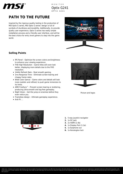
PATH TO THE FUTUREInspired by the rigorous quality testing in the production of MSI Optix G series, MSI Optix G series’ design is full ofsymbols of sturdiness and durability. Additionally, to provide quality user experience, Optix G series has really simple installation process and a friendly user interface, and will be the best choice for entry level gamers to step into the gameworld.Selling PointsIPS Panel – Optimize the screen colors and brightness to enhance your viewing experience.FHD High Resolution – Game titles will even look better, displaying more details due to the FHD resolution.144Hz Refresh Rate – Real smooth gaming.1ms Response Time – Eliminate screen tearing and choppy frame rates.Wide Color Gamut – Game colors and details will look more realistic and refined, to push game immersion to its limits.AMD FreeSync ® – Prevent screen tearing or stuttering,producing ultra-smooth and lag-free gameplay.Night Vision – Get the jump on enemies before they even notice you.Frameless design – Ultimate gameplay experience.Anti-Fli ...Picture and logos5-way joystick navigator 1.1x DC jack 2.2x HDMI (1.4b)3.1x Display Port (1.2a)4.1x Earphone out5.1x Kensington lock6.SpecificationSKU Number0Colour ID1/Black-BlackScreen Size23.8” (60cm)Active Display Area (mm)527.04(H) x 296.46(V) Curvature FlatPanel Type IPSResolution1920x1080 (FHD)Pixel pitch0.2745(H)X0.2745(V)Aspect Ratio16:9Dynamic Refresh Rate technology FreeSyncActivated Range48Hz-144HzHDR (High dynamic range)NASDR Brightness (nits)250Contrast Ratio1000:1DCR (Dynamic Contrast Ratio)100000000:1Signal Frequency30~180 KHz(H) / 47~145 Hz(V) Refresh Rate144HZResponse Time (MPRT)1ms(MPRT)Response Time (GTG)4msResponse Time (Tr + Tf)7.5msView Angles178°(H)/178°(V)NTSC (CIE1976 area percentageoverlap)111.3%/85.7%NTSC (CIE1931 area percentageoverlap)91.4%/81.5%sRGB (CIE1976 area percentageoverlap)127.7%/99.4%sRGB (CIE1931 area percentageoverlap)129%/99.9%Adobe RGB (CIE1976 area percentageoverlap)109.4%/90.3%Adobe RGB (CIE1931 area percentageoverlap)95.6%/84.8%DCI-P3 (CIE1976 area percentageoverlap)101.7%/94.6%DCI-P3 (CIE1931 area percentageoverlap)95.1%/92.7%Rec.709 (CIE1976 area percentageoverlap)127.7%/99.4%Rec.709 (CIE1931 area percentageoverlap)129%/99.9%Surface Treatment Anti-glareDisplay Colors16.7MColour bit8 bits (6 bits + FRC)Note_DP1920 x 1080 (up to 144Hz) Note_HDMI1920 x 1080 (up to 144Hz) Note_DVI N/AHDMI2HDMI version 1.4bHDMI HDCP version NADisplayPort1DisplayPort version 1.2aDisplayPort HDCP version NAThunderbolt version NAThunderbolt HDCP version NAUSB Type C (DisplayPort Alternate)NADVI NAD-Sub NAMic-in NAHeadphone-out1Audio Combo NAUSB 2.0 Type B NAUSB 3.2 Gen 1 Type B NALock type Kensington LockPower Type External Adaptor 20V 2.25A Power Input100~240V, 50/60HzAdapter's KC safety Number N/APower Cord Type C5QC Output NAQC Output Power NAPD Output NAPD Output Power NAAdjustment (Tilt)-5° ~ 20°Adjustment (Swivel)NAAdjustment (Height)NAAdjustment (Pivot)NAVESA Mounting100x100mmFrameless Design YesOuter Carton Dimension (WxDxH) (mm)621 x 187 x 434Outer Carton Dimension (WxDxH) (inch)24.45 x 7.36 x 17.09Product Dimension with Stand (WxDxH) (mm)540.3 x 219.6 x 422.6Product Dimension with Stand (WxDxH) (inch)21.27 x 8.65 x 16.64540.3 x 65.5 x 328.2Product Dimension without Stand (WxDxH)(mm)21.27 x 2.58 x 12.92Product Dimension without Stand (WxDxH)(inch)Thunderbolt NAUSB 2.0 Type A NAUSB 2.0 Type C NAUSB 3.2 Gen 1 Type A NAUSB 3.2 Gen 1 Type C NAUSB 3.2 Gen 2x2 Type C NAUSB 3.2 Gen 2x2 Type A NACard Reader NAStand Dimension (WxDxH) (mm)461.1 x 219.6 x 267.5Stand Dimension (WxDxH) (inch)18.15 x 8.65 x 10.53Feature Gaming ModeAdaptive Sync (Freesync)5 Ways Joystick Navigator ControlFrameless designMSI Gaming OSDNight VisionInside Carton Dimension (WxDxH) (mm)606 x 172 x 409Inside Carton Dimension (WxDxH) (inch)23.86 x 6.77 x 16.1Weight (Net kg) 3.3Weight (Gross kg)5DisplayPort Cable0HDMI Cable1DVI Cable0USB Type A to Type B Cable0USB Type C to Type A Cable0USB Type C to Type C Cable0Thunderbolt Cable0VGA Cable03.5mm audio Cable03.5mm combo audio Cable0Warranty36MPower Cord1AC Adaptor1Quick Guide1Warranty Card1EAN4719072688318。
G Series LCD Monitor G2412V (3BB7) G2712V (3CD4) 用

G Series LCD MonitorG2412V (3BB7) G2712V (3CD4) User GuideContentsGetting Started (3)Package Contents (3)Installing the Monitor Stand (4)Adjusting the Monitor (5)Monitor Overview (6)Connecting the Monitor to PC (8)OSD Setup (9)Navi Key (9)Hot Key (9)OSD Menus (10)Gaming (11)Professional (13)Image (14)Input Source (14)Navi Key (15)Setting (15)Specifications (17)Preset Display Modes (19)Troubleshooting (20)Safety Instructions (21)TÜV Rheinland Certification (23)Regulatory Notices (24)RevisionV1.0, 2023/052ContentsGetting StartedThis chapter provides you with the information on hardware setup procedures. While connecting devices, be careful in holding the devices and use a grounded wrist strap to avoid static electricity.∙Contact your place of purchase or local distributor if any of the items is damaged or missing.∙Package contents may vary by country.∙The included power cord is exclusively for this monitor and should not be used with other products.3Getting StartedInstalling the Monitor Stand 1. Leave the monitor in its protective foam packaging. Align the stand bracket to the monitor groove. Tighten the stand bracket with screws. 2. Align and push the stand cover towards the monitor groove until it locks in place.3. Connect the base to the stand and tighten the base screw to secure the base.4. Make sure the stand assembly is properly installed before setting the monitor Important ∙Place the monitor on a soft, protected surface to avoid scratching the display panel. ∙Do not use any sharp objects on the panel. ∙This product comes with NO protective film to be removed by the user! Any mechanical damages to the product including removal of the polarizing film may affect the warranty!Adjusting the MonitorThis monitor is designed to maximize your viewing comfort with its adjustment capabilities.⚠ImportantAvoid touching the display panel when adjusting the monitor.5Getting StartedMonitor Overview6Getting Started7 Getting StartedConnecting the Monitor to PC1. Turn off your computer.2. Connect the video cable from the monitor to your computer.3. Assemble the external power supply & power cord. (Figure A)4. Connect the external power supply to the monitor power jack. (Figure B)5. Plug the power cord into the electrical outlet. (Figure C)6. Turn on the monitor. (Figure D)7. Power on the computer and the monitor will auto detect the signal source.8Getting StartedOSD SetupThis chapter provides you with essential information on OSD Setup.⚠ImportantAll information is subject to change without prior notice.Navi KeyThe monitor comes with a Navi Key, a multi-directional control that helps navigate the∙selecting function menus and items∙adjusting function values∙entering into/exiting from function menusPress (OK):∙launching the On-Screen Display (OSD)∙entering submenus∙confirming a selection or settingHot Key∙Users may enter into preset function menus by moving the Navi Key up, down, left or right when the OSD menu is inactive.∙Users may customize their own Hot Keys to enter into different function menus.9OSD Setup10OSD Menus OSD Menus ⚠Important The following settings will be grayed out when HDR signals are received: ∙Night Vision ∙MPRT∙Low Blue Light ∙HDCR ∙Brightness ∙Contrast ∙Color Temperature11OSD Menus12OSD Menus13OSD Menus14OSD Menus15 OSD Menus16OSD Menus16.7M (6 bits + FRC)20VModel: ADPC204520V-5° ~ 20°17Specifications* Based on CIE1976 test standards. 18SpecificationsPreset Display ModesImportant19Preset Display ModesTroubleshootingThe power LED is off.• Press the monitor power button again.• Check if the monitor power cable is properly connected.No image.• Check if the computer graphics card is properly installed.• Check if the computer and monitor are connected to electrical outlets and areturned on.• Check if the monitor signal cable is properly connected.• The computer may be in Standby mode. Press any key to activate the monitor. The screen image is not properly sized or centered.• Refer to Preset Display Modes to set the computer to a setting suitable for themonitor to display.No Plug & Play.• Check if the monitor power cable is properly connected.• Check if the monitor signal cable is properly connected.• Check if the computer and graphics card are Plug & Play compatible. The icons, font or screen are fuzzy, blurry or have color problems.• Avoid using any video extension cables.• Adjust brightness and contrast.• Adjust RGB color or tune color temperature.• Check if the monitor signal cable is properly connected.• Check for bent pins on the signal cable connector.The monitor starts flickering or shows waves.• Change the refresh rate to match the capabilities of your monitor.• Update your graphics card drivers.• Keep the monitor away from electrical devices that may cause electromagneticinterference (EMI).20TroubleshootingSafety Instructions∙Read the safety instructions carefully and thoroughly.∙All cautions and warnings on the device or User Guide should be noted.∙Refer servicing to qualified personnel only.Power∙Make sure that the power voltage is within its safety range and has been adjusted properly to the value of 100~240V before connecting the device to the power outlet. ∙If the power cord comes with a 3-pin plug, do not disable the protective earth pin from the plug. The device must be connected to an earthed mains socket-outlet.∙Please confirm the power distribution system in the installation site shall provide the circuit breaker rated 120/240V, 20A (maximum).∙Always disconnect the power cord or switch the wall socket off if the device would be left unused for a certain time to achieve zero energy consumption.∙Place the power cord in a way that people are unlikely to step on it. Do not place anything on the power cord.∙If this device comes with an adapter, use only the MSI provided AC adapter approved for use with this device.BatteryPlease take special precautions if this device comes with a battery.∙Danger of explosion if battery is incorrectly replaced. Replace only with the same or equivalent type recommended by the manufacturer.∙Avoid disposal of a battery into fire or a hot oven, or mechanically crushing or cutting of a battery, which can result in an explosion.∙Avoid leaving a battery in an extremely high temperature or extremely low air pressure environment that can result in an explosion or the leakage of flammable liquid or gas.∙Do not ingest battery. If the coin/button cell battery is swallowed, it can cause severe internal burns and can lead to death. Keep new and used batteries away from children.European Union:Batteries, battery packs, and accumulators should not be disposed of asunsorted household waste. Please use the public collection system toreturn, recycle, or treat them in compliance with the local regulations. BSMI:廢電池請回收For better environmental protection, waste batteries should be collectedseparately for recycling or special disposal.21Safety InstructionsCalifornia, USA:The button cell battery may contain perchlorate material and requiresspecial handling when recycled or disposed of in California.For further information please visit: https:///perchlorate/ Environment∙To reduce the possibility of heat-related injuries or of overheating the device, do not place the device on a soft, unsteady surface or obstruct its air ventilators.∙Use this device only on a hard, flat and steady surface.∙To prevent the device from tipping over, secure the device to a desk, wall or fixedobject with an anti-tip fastener that helps to properly support the device and keep it safe in place.∙To prevent fire or shock hazard, keep this device away from humidity and hightemperature.∙Do not leave the device in an unconditioned environment with a storage temperature above 60℃ or below -20℃, which may damage the device.∙The maximum operating temperature is around 40℃.∙When cleaning the device, be sure to remove the power plug. Use a piece of softcloth rather than industrial chemical to clean the device. Never pour any liquid into the opening; that could damage the device or cause electric shock.∙Always keep strong magnetic or electrical objects away from the device.∙If any of the following situations arises, get the device checked by service personnel:• The power cord or plug is damaged.• Liquid has penetrated into the device.• The device has been exposed to moisture.• The device does not work well or you can not get it working according to the UserGuide.• The device has dropped and damaged.• The device has obvious sign of breakage.22Safety InstructionsTÜV Rheinland CertificationTÜV Rheinland Low Blue Light CertificationBlue light has been shown to cause eye fatigueand discomfort. MSI now offers monitors with TÜVRheinland Low Blue Light certification to ensureusers’ eye comfort and well-being. Please followthe instructions below to reduce the symptoms fromextended exposure to the screen and blue light.∙Place the screen 20 – 28 inches (50 – 70 cm) away from your eyes and a little below eye level.∙Consciously blinking the eyes every now and then will help to reduce eye strain after extended screen time.∙Take breaks for 20 minutes every 2 hours.∙Look away from the screen and gaze at a distant object for at least 20 seconds during breaks.∙Make stretches to relieve body fatigue or pain during breaks.∙Turn on the optional Low Blue Light function.TÜV Rheinland Flicker Free Certification∙TÜV Rheinland has tested this product toascertain whether the display produces visibleand invisible flicker for the human eye andtherefore strains the eyes of users.∙TÜV Rheinland has defined a catalogue oftests, which sets out minimum standardsat various frequency ranges. The test catalogue is based on internationally applicable standards or standards common within the industry and exceeds these requirements.∙The product has been tested in the laboratory according to these criteria.∙The keyword “Flicker Free” confirms that the device has no visible and invisible flicker defined in this standard within the range of 0 - 3000 Hz under various brightness settings.∙The display will not support Flicker Free when Anti Motion Blur/MPRT is enabled. (The availability of Anti Motion Blur/MPRT varies by products.)23TÜV Rheinland CertificationRegulatory NoticesCE ConformityThis device complies with the requirements set out in the Council Directive on the Approximation of the Laws of the Member States relating to Electromagnetic Compatibility (2014/30/EU), Low-voltage Directive (2014/35/EU), ErP Directive (2009/125/EC) and RoHS directive (2011/65/EU). This product has been tested and found to comply with the harmonized standards for Information Technology Equipment published under Directives of Official Journal of the European Union.FCC-B Radio Frequency Interference StatementThis equipment has been tested and found to comply with the limitsfor a Class B digital device, pursuant to Part 15 of the FCC Rules.These limits are designed to provide reasonable protection against harmful interference in a residential installation. This equipment generates, uses and can radiate radio frequency energy and, ifnot installed and used in accordance with the instruction manual, may cause harmful interference to radio communications. However, there is no guarantee that interference will not occur in a particular installation. If this equipment does cause harmful interference to radio or television reception, which can be determined by turning the equipment off and on, the user is encouraged to try to correct the interference by one or more of the measures listed below:∙Reorient or relocate the receiving antenna.∙Increase the separation between the equipment and receiver.∙Connect the equipment into an outlet on a circuit different from that to which thereceiver is connected.∙Consult the dealer or an experienced radio/television technician for help. Notice 1The changes or modifications not expressly approved by the party responsible for compliance could void the user’s authority to operate the equipment. Notice 2Shielded interface cables and AC power cord, if any, must be used in order to comply with the emission limits.This device complies with Part 15 of the FCC Rules. Operation is subject to the following two conditions:1. This device may not cause harmful interference, and2. This device must accept any interference received, including interference that maycause undesired operation.MSI Computer Corp.901 Canada Court, City of Industry, CA 91748, USA(626) 913-082824Regulatory NoticesWEEE StatementUnder the European Union (“EU”) Directive on Waste Electrical and Electronic Equipment, Directive 2012/19/EU, products of “electrical and electronic equipment” cannot be discarded as municipal waste anymoreand manufacturers of covered electronic equipment will be obligated totake back such products at the end of their useful life. Chemical Substances InformationIn compliance with chemical substances regulations, such as the EU REACH Regulation (Regulation EC No. 1907/2006 of the European Parliament and the Council), MSI provides the information of chemical substances in products at: https:///global/indexRoHS StatementJapan JIS C 0950 Material DeclarationA Japanese regulatory requirement, defined by specification JIS C 0950, mandates that manufacturers provide material declarations for certain categories of electronic products offered for sale after July 1, 2006.https:///global/Japan-JIS-C-0950-Material-DeclarationsIndia RoHSThis product complies with the “India E-waste (Management and Handling) Rule 2016” and prohibits use of lead, mercury, hexavalent chromium, polybrominated biphenylsor polybrominated diphenyl ethers in concentrations exceeding 0.1 weight % and 0.01 weight % for cadmium, except for the exemptions set in Schedule 2 of the Rule. Turkey EEE RegulationConforms to the EEE Regulations of the Republic Of TurkeyUkraine Restriction of Hazardous SubstancesThe equipment complies with requirements of the Technical Regulation, approved by the Resolution of Cabinet of Ministry of Ukraine as of 10 March 2017, № 139, in terms of restrictions for the use of certain dangerous substances in electrical and electronic equipment.Vietnam RoHSAs from December 1, 2012, all products manufactured by MSI comply with Circular 30/2011/TT-BCT temporarily regulating the permitted limits for a number of hazardous substances in electronic and electric products.25Regulatory Notices26Regulatory Notices Green Product Features∙Reduced energy consumption during use and stand-by ∙Limited use of substances harmful to the environment and health∙Easily dismantled and recycled ∙Reduced use of natural resources by encouraging recycling ∙Extended product lifetime through easy upgrades ∙Reduced solid waste production through take-back policy Environmental Policy ∙The product has been designed to enable proper reuse of parts and recycling and should not be thrown away at its end of life. ∙Users should contact the local authorized point of collection for recycling and disposing of their end-of-life products. ∙Visit the MSI website and locate a nearby distributor for further recycling information. ∙*******************************************************************disposal, take-back, recycling, and disassembly of MSI products.Warning!Overuse of screens is likely to affect eyesight.Recommendations: 1. Take a 10-minute break for every 30 minutes of screen time. 2. Children under 2 years of age should have no screen time. For children aged 2 years and over, screen time should be limited to less than one hour per day.Copyright and Trademarks Notice Copyright © Micro-Star Int’l Co., Ltd. All rights reserved. The MSI logo used is a registered trademark of Micro-Star Int’l Co., Ltd. All other marks and names mentioned may be trademarks of their respective owners. No warranty as to accuracy or completeness is expressed or implied. MSI reserves the right to make changes to this document without prior notice.The terms HDMI™, HDMI™ High-Definition Multimedia Interface, HDMI™ Trade dress and the HDMI™ Logos are trademarks or registered trademarks of HDMI™ Licensing Administrator, Inc.Technical Support If a problem arises with your product and no solution can be obtained from the user’s manual, please contact your place of purchase or local distributor. Alternatively,please visit https:///support/ for further guidance.。
Dell S2419H S2419HN S2419NX S2719H S2719HN S2719N

用户指南Dell S2419H/S2419HN/S2419NX/S2719H/S2719HN/S2719NX认证型号:S2419H/S2419HN/S2419NX/S2719H/S2719HN/ S2719NX注、注意和警告注:“注”表示可以帮助您更好使用显示器的重要信息。
注意:“注意”表示如果不按照说明进行操作,可能造成硬件损坏或数据丢失。
警告:“警告”表示可能会造成财产损失、人身伤害或死亡。
_________________________本文档中的信息如有变更,恕不另行通知。
© 2018 Dell Inc. 保留所有权利。
未经Dell Inc.书面许可,严禁以任何形式复制这些资料。
本文中使用的商标:Dell和DELL徽标是Dell Inc.的商标;Microsoft和Windows是Microsoft Corporation在美国和/或其他国家(地区)的商标或注册商标,Intel是Intel Corporation在美国和其他国家(地区)的注册商标;ATI是Advanced Micro Devices, Inc.的商标。
ENERGY STAR是美国环境保护署的注册商标。
作为ENERGY STAR的合作伙伴,Dell Inc.认定本产品符合ENERGY STAR在能效方面的要求。
本文中使用的其他商标和品牌名称是指拥有这些标志和名称的实体或它们的产品。
Dell Inc.对于自身之外的商标和品牌名称没有任何专有利益。
2018 - 03 Rev. A01目录关于您的显示器 (5)物品清单 (5)产品特性 (6)识别部件和控制按钮 (7)显示器规格 (10)即插即用功能 (19)液晶显示器质量和像素政策 (19)维护指南 (19)安装显示器 (20)连接底座 (20)连接显示器 (22)整理线缆 (23)卸下底座 (23)操作显示器 (25)打开显示器电源 (25)使用控制按钮 (25)使用屏幕显示(OSD)菜单 (27)设置显示器 (36)使用倾斜度 (38)目录 | 3故障排除 (39)自检 (39)内置诊断 (40)常见问题 (41)产品特有的问题 (43)附录 (44)FCC声明(仅限美国)和其他管制信息 (44)联系Dell (44)4 |关于您的显示器物品清单此显示器在出厂时包括如下所示的物品。
- 1、下载文档前请自行甄别文档内容的完整性,平台不提供额外的编辑、内容补充、找答案等附加服务。
- 2、"仅部分预览"的文档,不可在线预览部分如存在完整性等问题,可反馈申请退款(可完整预览的文档不适用该条件!)。
- 3、如文档侵犯您的权益,请联系客服反馈,我们会尽快为您处理(人工客服工作时间:9:00-18:30)。
JY2412 Soft-Start Technology Constant-Current LEDDriving ICFigure 1a Typical application circuitFigure 1b Typical application circuitOverviewJY2412 LED constant-current driving IC is the updated version of JY2410es series.It is specially designed for low-power lighting products such as LED bulb, LED tube, ceiling lamp and down lamp to meet their features and requirements.JY2412 is based on JY2411 and added another constant-current driving module. JY2412 has two channel A, B. Here, channel A with internal MOS power tubes (600V) which enables the output a maximum current of 80 mA. Channel B uses external MOS to drive. These two channel has their own current sampling ports and can work independently.In addition to the excellent electrical performance of JYxxxx series, JY2412 has also used our company’s latest LED soft-start patented technology. At the power-on moment, the beginning current is only 20% of the working current. Then it increases generally to 100% in 5s. Such soft-start technology can thoroughly avoid the impact to the LED lighting sources resulted by the power-on peak current and can extend the LED’s service life.Pin definitionProduct featuresJY2412 integrates two independent linear constant-current modules, external remote controlling connecting module, external PMW dimming module, temperature controlling module, etc. It is suitable for the design of high voltage non-isolated LEDdrivers. A channel uses internal MOS tubes which can offer a maximum current of 80mA and meet the requirement of the low-power products. B channel uses external MOS tubes which can be adjusted and replaced flexibly according to the customers’ requirements and can drive a current more than 150mA and a power over 100W. JY2412 has various practical features, simple peripheral circuits and high reliability.Functions●Power-on soft-start technology to avoid current shock to LEDJY2412 has also used our company’s latest LED soft-start patented technology. At the power-on moment, the beginning current is only 20% of the working current. Then it increases generally to 100% in 5s. Such soft-start technology can thoroughly avoid the impact to the LED lighting sources resulted by the power-on peak current and can extend the LED’s service life.●External sensor controlling portJY2412 offers an external sensor controlling port HAL which can connect with sensors or timers. When HAL is set 0V, the output current will decrease to 50%. This function can be applied in street lamps as timing switch to decrease the power in the time after midnight to save energy. It can also be used in hotels, hospitals, parks and others with connecting to sensors which deceases the power if no people or cars passing by to save energy and extend the lamps’ life.●External PWM dimming portJY2412 offers an external PWM dimming port DIM. The maximum peak voltage of the input impulse signals is 5V. The output current would be changed by changing the input impulses’ widths. The DIM port can connected with any MCU and other intelligent control modules to realize the functions of intelligent controlling or mobile phones’ APP contr olling.●Intelligent temperature protectionJY2412 has the function of intelligent temperature controlling. When the chip junction temperature reaches 100℃, the chip would decrease the output currentautomatically. When the chip junction temperature reaches 150℃, the chip would turn off and lock until turn off the power and repower-on.Figure 3Figure 3 shows the temperature performance under the conditions of 220V AC input and 60mA output.JY2412 can work in very low temperature environment and has passed low temperature tests.●Applying low power CMOS process, high integration and patentedtechnologiesJY2412 integrates two independent linear constant-current modules, external remote controlling connecting module, external PMW dimming module, temperature controlling module, etc.●High power factor and high reliabilityAny products of JYxxxx constant-current series can work without capacities and reach a high power factor of 0.97. JY2412 has high reliability with a trouble-free time over 50000 hours. It supports general SCR elements and external PWM dimming. DIM port can connect with any MCU to achieve the goal of intelligent controlling or dimming.●High accuracy of constant currentJY2412 has a very high accuracy of constant current. It can also keep a constant current in the area where voltage is very unsteady.Figure 4Figure 4 shows the VI performance under the conditions of 60mA output and a range of input voltage of 190V~260V.●Linear driving without EMIJY2412 works under the linear situation and provide no electro-magnetic interference (EMI) while working. It can pass any tests of EMC and EMI.●Few peripheral elements and simple applying circuitsWith simple peripheral circuits and few elements, JY2412 can be applied in many occasions. It can be used directly on the lighting source boards to integrate the drivers and the lighting sources to cut cost.●Intelligent joint control mechanism between temperature and dropout voltageThe most obvious disadvantage of the normal linear constant-current drivers is that the IC has to undertake the dropout voltage. So, when the power voltage exceed the normal range, the driving circuits would consume more power and the temperature would increase. High temperature would influence the circuits’ stabili ty and theproducts’ reliability.JY2412 applies the intelligent joint control mechanism between temperature and dropout voltage to solve the problem mentioned above. While working, the system would adjust the output power automatically according to the temperature, power and dropout voltage. When the temperature is higher than 120℃ or the input voltage exceeds the normal range, the IC would decrease the output power. The output power would increase to the normal value when the temperature or the input voltage return to the normal range. Also, when the IC detects that the temperature of the lighting sources is too high, it would decrease the power as well to protect the LEDs and extend their life.JY2412 inside structureApplicationJY2412 is suitable to be applied in high-power LED lighting products such as LED bulbs, LED tubes, ceiling lamps and down lamps. Equipped with sensors, it can also be DC/DCExternal sensor port PWM input port Temperature/dropout voltSoft-startInformation processingused in hotels, office buildings, hospitals and underground parks. JY2412 can achieve the real automatic energy-saving lighting.Figure 1 shows a typical application circuit. Sampling voltage is 0.3V coming from Rcs at the source electrodes of MOS tubes. The resistance value can be decided according to the constant current with the formula:Rcs=V/I.Here, Rcs is the current sampling resistance which is connected to the source electrodes in series. V is the sampling voltage of JY2412, which is 0.3V normally. I is the output current of LEDs. For example, if the LEDs current needed is 60mA, then the R should be 0.3 (V) / 0.06 (A) = 5Ω. The rest can be done in the same manner.In the typical application circuit, the value of R1 is 510k-810k and the C1 is 1 -2.2 uf 35v.The sixth pin of JY2412 is the external PWM dimming port. It can connect to MCU directly. By outputting PWM signals, MCU can dim the lights. JY2412 can also use DC voltage of 0-5V input into DIM port to dim. Figure 5 shows how to connect.The second pin of JY2412 is HAL, the half-power enable port. When input low level, the output power of both channels would decrease 50%. In some occasions like hotels or underground parks, with connecting to sensors, the chip output 50% of the full power in normal time and increase to 100% when people or cars pass by. Typically, the port connects to ground through a switching diode 1N4148. When the sensors output low level, the chip output 50% of the full power. When the sensors output high level, the chips output full power. This port can connect with timer as well to control street lamps and save energy in the time after midnight. Figure 6 shows how to connect.SensorFigure 6PackagingJY2412 can be applied in areas with electric supply voltage of AC220V-240V or AC100V-120V.Working voltage range:Areas with supply voltage of AC220V: AC190V -260V.Areas with supply voltage of AC110V: AC85V -135V.。