AVST-X3标清移动审讯光盘直刻终端说明书
三核监视器的用户手册说明书

T riCore Monitor Release 09.2023TRACE32 Online HelpTRACE32 DirectoryTRACE32 IndexTRACE32 Documents ...................................................................................................................... ICD In-Circuit Debugger ................................................................................................................ Processor Architecture Manuals .............................................................................................. TriCore ...................................................................................................................................... TriCore Monitor .. (1)Introduction (4)Brief Overview of Documents for New Users4 Quick Start of the TriCore Serial Monitor (5)Troubleshooting (6)FAQ (6)Basics (7)Monitor Features7General SYStem Settings and Restrictions (8)SYStem.CPU CPU type8 SYStem.CpuAccess Run-time memory access (intrusive)8 SYStem.Down Disables monitor9 SYStem.MemAccess Real-time memory access (non-intrusive)9 SYStem.Mode Establish the communication with the CPU10 SYStem.Option.IMASKASM Disable interrupts while single stepping11 SYStem.Option.IMASKHLL Disable interrupts while HLL single stepping11TrOnchip (12)TrOnchip.CONVert Adjust range breakpoint in on-chip resource12 TrOnchip.VarCONVert Adjust complex breakpoint in on-chip resource12 TrOnchip.RESet Set on-chip trigger to default state13 TrOnchip.TEnable Set filter for the trace13 TrOnchip.TOFF Switch the sampling to the trace to OFF13 TrOnchip.TON Switch the sampling to the trace to “ON”13Memory Classes (14)Version 10-Oct-2023IntroductionThis document describes the processor specific settings and features of the T riCore ROM Monitor. Y ou can find the description of the OCDS-L1 Debugger for the T riCore family at “TriCore Debugger and Trace”(debugger_tricore.pdf).Please keep in mind that only the Processor Architecture Manual (the document you are reading at the moment) is CPU specific, while all other parts of the online help are generic for all CPUs supported by Lauterbach. So if there are questions related to the CPU, the Processor Architecture Manual should be your first choice.Brief Overview of Documents for New UsersArchitecture-independent information:•“Training Basic Debugging” (training_debugger.pdf): Get familiar with the basic features of a TRACE32 debugger.•“T32Start” (app_t32start.pdf): T32Start assists you in starting TRACE32 PowerView instances for different configurations of the debugger. T32Start is only available for Windows.•“General Commands” (general_ref_<x>.pdf): Alphabetic list of debug commands.Architecture-specific information:•“Processor Architecture Manuals”: These manuals describe commands that are specific for the processor architecture supported by your Debug Cable. T o access the manual for your processorarchitecture, proceed as follows:-Choose Help menu > Processor Architecture Manual.•“OS Awareness Manuals” (rtos_<os>.pdf): TRACE32 PowerView can be extended for operating system-aware debugging. The appropriate OS Awareness manual informs you how to enable theOS-aware debugging.Quick Start of the TriCore Serial MonitorStarting up the ROM Monitor is done as follows:6.Select the device B: for the ROM Monitor.7.Transition to the down mode before pressing the reset button.This instruction is necessary when the system is restarted.8.Set the CPU type in the ROM Monitor program:9.Define the communication parameters.10.Activate the ROM monitorA typical start sequence is shown below:The start-up can be automated using the programming language PRACTICE.B:SYStem.Mode DownSYStem.CPU TC1796SYStem.PORT COM2 BAUD=38400SYStem.Up; for this example the TriBoard TC1796 Evaluation board is used B:SYStem.Mode Down WinCLREARSYStem.CPU tc1796 SYStem.PPORT COM2 BAUD=38400; select the Debugger device ; switch the system down ; clear all windows; set the CPU type for the user interfaceSYStem.Mode UpTroubleshooting No information available. FAQNo information availableBasicsMonitor FeaturesThe monitor requires no stack.General SYStem Settings and RestrictionsSYStem.CPU CPU type Format:SYStem.CPU <cpu><cpu>:TC1792 | TC1796 | TC1796EDSelects the processor type. The ROM debugger requires also a modification in the debug monitor fordifferent processor types.SYStem.CpuAccess Run-time memory access (intrusive) Format:SYStem.CpuAccess Enable | Denied | NonstopDefault: Denied.Enable Allows intrusive run-time memory access.In order to perform a memory read or write while the CPU is executingthe program, the debugger stops the program execution shortly. Eachshort stop takes 1…100ms depending on the speed of the debuginterface and on the number of the read/write accesses required.A white S against a red background in the state line of the TRACE32 mainwindow indicates this intrusive behavior of the debugger.Denied Locks intrusive run-time memory access.Nonstop Locks all features of the debugger that affect the run-time behavior.Nonstop reduces the functionality of the debugger to:•Run-time access to memory and variables•Trace displayThe debugger inhibits the following:•To stop the program execution•All features of the debugger that are intrusive (e.g. action Spot forbreakpoints, performance analysis via StopAndGo mode, condi-tional breakpoints, etc.)SYStem.Down Disables monitor Format:SYStem.DownSYStem.MemAccess Real-time memory access (non-intrusive) Format:SYStem.MemAccess Enable | StopAndGo | Denied | NEXUS |<cpu_specific>SYStem.ACCESS (deprecated)Real-time memory access during program execution to target is enabled.EnableCPU (deprecated)Denied (default)Real-time memory access during program execution to target is disabled.StopAndGo Temporarily halts the core(s) to perform the memory access. Each stoptakes some time depending on the speed of the JT AG port, the number ofthe assigned cores, and the operations that should be performed.For more information, see below.NEXUS Memory access is done via the NEXUS interface.SYStem.Mode Establish the communication with the CPU Format:SYStem.Mode <mode><mode>:DownNoDebugGoUpDefault: Down. Selects the target operating mode.Down The CPU is in reset. Debug mode is not active. Default state and state after fatalerrors.NoDebug The CPU is running. Debug mode is not active. Debug port is tristate. In thismode the target should behave as if the debugger is not connected.Go The CPU is running. Debug mode is active. After this command the CPU can bestopped with the break command or if any break condition occurs.Up The CPU is not in reset but halted. Debug mode is active. In this mode the CPUcan be started and stopped. This is the most typical way to activate debugging.If the mode “Go” is selected, this mode will be entered, but the control button in the SYStem window jumps to the mode “UP”.SYStem.Option.IMASKASM Disable interrupts while single stepping Format:SYStem.Option.IMASKASM [ON | OFF]Default: OFF.If enabled, the interrupt mask bits of the CPU will be set during assembler single-step operations. The interrupt routine is not executed during single-step operations. After single step the interrupt mask bits are restored to the value before the step.SYStem.Option.IMASKHLL Disable interrupts while HLL single stepping Format:SYStem.Option.IMASKHLL [ON | OFF]Default: OFF.If enabled, the interrupt mask bits of the CPU will be set during HLL single-step operations. The interrupt routine is not executed during single-step operations. After single step the interrupt mask bits are restored to the value before the step.TrOnchipTrOnchip.CONVertAdjust range breakpoint in on-chip resource The on-chip breakpoints can only cover specific ranges. If a range cannot be programmed into thebreakpoint, it will automatically be converted into a single address breakpoint when this option is active. This is the default. Otherwise an error message is generated.TrOnchip.VarCONVertAdjust complex breakpoint in on-chip resource The on-chip breakpoints can only cover specific ranges. If you want to set a marker or breakpoint to a complex variable, the on-chip break resources of the CPU may be not powerful enough to cover the whole structure. If the option TrOnchip.VarCONVert is set to ON , the breakpoint will automatically be converted into a single address breakpoint. This is the default setting. Otherwise an error message is generated. Format:TrOnchip.CONVert [ON | OFF ] (deprecated)Use Break.CONFIG.InexactAddress insteadTrOnchip.CONVert ONBreak.Set 0x1000--0x17ff /WriteBreak.Set 0x1001--0x17ff /Write…TrOnchip.CONVert OFFBreak.Set 0x1000--0x17ff /WriteBreak.Set 0x1001--0x17ff /Write ; sets breakpoint at range ; 1000--17ff sets single breakpoint ; at address 1001; sets breakpoint at range ; 1000--17ff ; gives an error messageFormat:TrOnchip.VarCONVert [ON | OFF ] (deprecated)Use Break.CONFIG.VarConvert insteadTrOnchip.RESet Set on-chip trigger to default state Format:TrOnchip.RESetSets the T rOnchip settings and trigger module to the default settings.TrOnchip.TEnable Set filter for the trace Format:TrOnchip.TEnable <par> (deprecated)Refer to the Break.Set command to set trace filters.TrOnchip.TOFF Switch the sampling to the trace to OFF Format:TrOnchip.TOFF (deprecated)Refer to the Break.Set command to set trace filters.TrOnchip.TON Switch the sampling to the trace to “ON”Format:TrOnchip.TON EXT | Break (deprecated)Refer to the Break.Set command to set trace filters.Memory ClassesMemory Class DescriptionD DataP ProgramC Memory access by CPUE Emulation memory accessA Absolute (physical) memory access。
X射线荧光检测仪操作规程
X射线荧光检测仪操作规程
一、开机:
依次开启仪器电源(包括照明和高压开关),打印机、计算机、TFM软件。
二、测量前的准备:
1、预热仪器:为了保证测量结果的准确性和稳定性,仪器必
须在不间断的情况下预热30分钟。
2、基准测量:
因为仪器是以AG 为基准进行测量的所以仪器预热结束后必须精确定位元素AG的位置,不能偏移,一般情况下,一周做一次“测量基准”即可。
三、进行测量:
1、根据待测样品的检测项目,选择相应的检测程式。
2、将样品放置在工作台上,调整其位置并聚焦清晰。
使其清
楚的显示在视频窗口十字线中央。
3、按显示屏左下角的按扭“测量”,或仪器控制台上的
“START”键开始测量,倒计时间结束后完成一次测量。
四、报告:
打印机打印出样品照片和测量数据。
五、关机:
依次关闭TFM软件、计算机和打印机软件及仪器。
浙江明泰标准件有限公司。
X射线机使用说明书
上方检测目录一、产品主要参数一览表 (2)二、产品概述 (5)三、工作原理简述 (5)四、使用说明 (6)五、注意事项 (11)六、维修指南 (12)七、曝光参考曲线表 (13)一、产品主要技术参数一览表SF系列XXG、XXQ系列二、产品概述我公司生产的SF系列X射线探伤机和XXQ、XXG系列X射线探伤机,采用变频和恒频脉冲式控制技术,具有结构新颖、携带方便、功能齐全等特点,系统采用微机控制和调节,模块化结构,保证了整机的稳定性与可靠性,并且维修特别方便,具有齐全的保护功能,适用范围宽;各种参数设定、工作状态、保护动作都有语言用汉语提示,方便了用户的使用,防止各种违章操作,设备设有训机功能,提高了整机的使用寿命。
本机的X射线发生器采用气体绝缘强迫风冷阳极接地式,具有体积小、重量轻等优点。
该产品适用于高空作业、薄钢材、小型、中型、大型容器类焊接工程、造船业、锅炉管道焊缝、石化工程、飞机制造、维修业、汽车工业、国防工业等部门的无损检测。
整机特点可归纳如下:●采用微机控制,模块化结构,自动化程度高,抗干扰能力强,工作可靠;●参数设置、工作过程、故障指示采用LED数码管和LED指示灯,同时配以汉语语音提示;●自带训机键,可方便对设备老练;●XXG、XXQ曝光时间与休息时间严格按1:1进行;SF系列X射线探伤机为连续工作型。
●根据不同的输出电压,采用不同的启动频率,提高工作效率。
●防尘防水彩色薄膜面板,语言提示键盘,可以迅速准确地选择曝光参数;●具有灵敏的过压、欠压、过流、欠流、超温等保护功能;●独特的安全锁设计,使操作人员免受意外的射线伤害;●配有安全射线指示灯插座,可接射线指示灯●配有探伤室用门机连锁接线端子,可随时连接铅门开关,确保人员安全。
●具有宽的千伏选择范围,解决了其它系列探伤机透照厚度范围窄的难题;●延时曝光功能,可设置小于10分钟的延时曝光时间,以便操作人员远离现场;●自动测试电网电压特性,故可配接各种发电机可靠工作,●采用探伤机专用快速接插件、及特种高强度连接电缆。
数字光纤直放站用户手册
GSM900/DCS1800 数字光纤直放站
用户手册
深圳市西瑞克斯通信设备有限公司 Shen Zhen Cylix Technology Communication Equipment
Co.,Ltd.
密级:公开
GSM900/DCS1800 数字光纤直放站用户手册
目录
第一章 系统概述 ...................................................................................................................... 3 1.1 概述 ............................................................................................................................... 3 1.2 基本原理 ....................................................................................................................... 4 1.3 组网方式 ....................................................................................................................... 5 1.4 产品特点 ....................................................................................................................... 7 1.5 技术指标 ....................................................................................................................... 8 1.5.1 主要技术指标 .................................................................................................. 8 1.5.2 机械特性 .......................................................................................................... 9 1.5.3 接口 .................................................................................................................. 9
移动警务终端用户手册新版

移动警务终端用户手册1 / 39前言忠心感谢您使用本公司产品,我们将竭诚为您提供最优质的服务。
本手册内容仅供参考,本手册内容将根据产品功能的增强而更新,如有更新恕不另行通知,更新内容将会在本手册的更新版本中加入。
本手册可能包含技术上不准确的地方或产品功能及操作不相符的地方或印刷错误,真诚希望您把意见及时反馈给我们,在以后的版本中,我们会加以充实和改进。
2 / 39目录1. 产品概述 (1)2. 安全须知 (1)2.1一般安全 (1)2.2电池安全 (1)2.3充电器安全 (2)3. 设备说明 (3)4. 操作指引 (4)4.1开机 (4)4.2电池 (4)4.3充电 (5)4.4使用数据线 (6)4.5数据同步操作 (6)5. 操作说明 (12)5.1查人 (14)5.1.1 二代证查询 (14)5.1.2 手动录入查询 (16)5.2查车 (19)5.3万能查询 (20)5.4记录查询 (21)5.5拍照 (22)5.6照片浏览 (23)5.7卡授权 (23)5.8指纹授权 (25)5.9系统信息 (27)5.10系统维护 (28)5.11时间设置 (29)5.12切换用户 (30)5.13关机操作 (31)附录A 常见问题解答 (32)附录B 装箱单 (34)1. 产品概述移动警务终端让民警利用此智能设备作为民警的标准装备,完成路面盘查,人员、物品、运动轨迹的动态采集,革命性地让民警从“被”使用电脑的困境中解放出来,轻装上阵,解放警力。
该设备有二代证安全模块,13.56射频全能型读头,13.56射频卡写入模块,警用指纹采集模块,指纹比对模块,300万像素摄像头,USB接口,数字及功能键盘,3.2寸彩屏,工业三防外观设计。
能够自动读取二代证信息和指纹信息以及SIM卡,读取和写入13.56M的IC卡芯片信息,脱机比对在逃及敏感人群,拍摄车牌号,并脱机比对涉案车辆,还能采集指纹和比对指纹,采集人员照片,联机公安网同步数据,进行密集信息查询,同现有的公安社区管理系统和警综系统无缝结合。
X射线安全检查设备用户手册.

1.2
本产品具有以下六大特色,为用户提供更具方便快捷的服务:
★环保铅帘:铅帘的外表经过特定的处理,耐磨且环保,延长使用寿命
★紧停分层控制:按下紧停按钮,仅断电传动和射线源部分,更安全。
★射线更安全:射线发射自动控制,避免误发射
★一键关机控制:关机时只需旋转一下钥匙,设备自动安全关机,简洁方便
(1)专用驱动程序
(2)用户控制界面
控制系统硬件实现数据采集自动化
定时读取数据采集系统
为图像处理提供接口
分析处理显示图像的输出
提供友好的用户界面
由软件将传输过来的信号进行复杂的数据处理,将处理后的图像显示在屏幕上,供操作人员进行辨别。软件提供边缘增强、反色显示、伪彩色、局部穿透增强等图像处理功能,便于对违禁物品进行识别,同时具有图像回拉、放大等图像处理功能及图像存储功能(50000幅以上)。
软件部分包括:
(1)系统控制部分
(2)图像处理部分
系统组成框图如下:
图3.1系统组成框图
3.1
系统中包括的部件和子部件如下:
(1)X射线源
(2)X射线源控制和驱动装置
(3)X射线探测器阵列盒
(4)电子控制单元
(5)工控机
(6)显示器
(7)中间继电器
(8)钥匙开关
(9)散热风扇
(10)传送带
(11)光障
6、我公司生产的X射线安检系统完全符合X射线国家标准GB15208-2005.1中的安全要求。
设备的设计,在任何情况下均能保护操作及维修人员的安全。该系统具有极低的X射线剂量,同时又能保证对被检查物体有足够的穿透力,感光材料、食品、药物及磁带均不受影响,甚至多次照射也无妨。该设备配有大面积铅屏蔽以防止X射线泄漏。一套铅门帘几乎将射线对外辐射降低为零。设备在X射线的出射处和探测器箱上,装有安全联锁开关,控制电路随时监测这些联锁开关的工作情况。任一联锁开关断开,设备将自动切断X射线控制器的交流供电,从而关断X射线。该设备的X射线源在电源切断后不能发射X射线。
威盛WM8650中文说明书V0.3(7寸)

资料来源:爱购机目录................................................................................................... 错误!未定义书签。
1 外观描述 (2)2 电源键的用法 (3)3 触摸屏 (4)4转接盒 (4)5 SD卡的使用 (5)6开始使用 (5)给设备充电 (5)启动设备 (5)Wi-Fi 网络设置 (5)7桌面 (5)8锁屏界面 (6)9预装程序 (7)10桌面菜单功能 (8)11 程序管理 (10)安装程序 (10)直接从网络上下载程序 (10)卸载程序 (10)12 天气 (10)13 时钟 (11)闹钟 (11)14在线软件安装 (12)菜单功能 (12)15浏览器 (13)16 日历 (13)新建活动 (13)17 相机 (13)拍摄图片 (13)录制视频 (14)18 计算器 (14)19 电子邮件 (14)添加邮件账户 (14)收件箱 (15)编辑邮件账户 (15)删除邮件账户 (16)20 文件浏览器 (16)在电脑和设备之间拷贝文件 (17)删除文件 (17)21 我的音乐 (17)播放音乐 (17)对音乐盒播放列表进行操作 (18)22 我的视频 (18)播放视频 (18)对视频和播放列表进行操作 (19)23 我的相册 (19)涂鸦 (20)24 通讯录 (20)添加新的联系人 (20)添加联系人到收藏 (20)编辑联系人 (20)删除联系人 (20)25 图片截取 (21)26 程序管理器 (21)停止程序 (21)卸载程序 (21)27 YouTube (21)28 土豆视频 (22)29 Wi-Fi设置 (22)30 3G Settings (22)31 连接ADSL上网 (23)32 有线网络 (23)33 设置 (23)常见问题 (25)电池管理 (26)电池充电 (26)重要安全提示 (26)附录.建议可选配件及型号 (27)1 外观描述前视图:右视图:左视图:顶视图:2 电源键的用法开机: 长按电源键2秒。
光机操作手册中文

X射线安检设备操作手册广州市克金安防科技有限企业目录一、前言二、系统概述三、设备安装四、系统操作五、保养维护一、前言克金X射线安全检查设备是目前全球科技领先旳X射线成像系统。
该设备综合了高下能阵列探测器、数字化图像处理技术和计算机即时图像显示技术等诸多长处, 为顾客提供高效可靠和具有服务功能旳高质量图像。
为了使广大顾客对本设备有全面旳理解, 同步也更以便旳使用该设备, 特编写了此顾客手册。
本手册全面地简介了克金X射线安全检查设备旳工作原理以及怎样调整维护、维护和保养。
在使用X射线安全检查设备前, 请仔细阅读本手册。
对于顾客不遵守安全规范而损坏了设备, 我司不承担任何责任。
本设备应由接受过正规培训旳人员操作。
为防止射线旳危害, 操作人员必须一直严格遵守射线防护规则。
广州市克金安防科技有限企业拥有本手册旳版权。
未经我司或其授权代理旳书面许可, 不得以任何形式旳手段复制本手册。
由于时间精力有限, 该手册难免有疏漏和局限性之处, 敬请广大顾客、专家予以批评指正。
二、系统概述1.工作原理设备是借助于输送带将被检查行李送入X射线检查通道而完毕检查旳。
行李进入X射线检查通道, 将阻挡包裹检测传感器, 检测信号被送往系统控制部分, 产生X射线触发信号, 触发X射线射线源发射X射线束。
一束通过准直器旳扇形X射线束穿过输送带上旳被检物品, X射线被被检物品吸取, 最终轰击安装在通道内旳双能量半导体探测器。
探测器把X射线转变为信号, 这些很弱旳信号被放大, 并送到信号处理机箱做深入处理。
2.技术指标一般指标通道尺寸: 500*300 650*500 800*650 1000*800 1000*1000传送带速度: 0.2m/s传送带最大负荷: 200kg辨别力: 直径0.10mm金属线穿透力: >30mm胶卷安全性: 对ISO1600胶卷安全泄漏剂量: <1.5µGy/hX射线发生器管电流: 0.4mA~1.2mA管电压: 100~160KV射线束发散角: 60°冷却方式: 密封式油冷工作周期: 100%图像系统X射线传感器: L形光电二极管阵列探测器显示屏: 高辨别率22英寸液晶显示屏多能高穿透: 显示高能多穿透彩色/黑白图像: 彩色/黑白图像切换部分剔除: 有机物、无机物、混合物剔除图像锐化: 边缘锐化效果图像放大: 图像放大效果图像增亮: 图像亮度逐层加亮图像细化: 图像细节度增长图像检索: 图像回放搜索报警: 对不可穿透或可疑物报警图像回拉: 显示已过图像安装数据工作温度/湿度: 0℃~45℃/20%~95%(不冷凝)储存温度/湿度: -20℃~60℃/20%~95%(不冷凝)工作电压: 220V AC(±10%)功率损耗: 1.0KW(最大)噪声级: <65dB其他功能时间日期显示操作员识别急停工作状态显示外接打印机端口外接U盘接口X射线状态识别3.重要用途X射线安全检查设备广泛合用于机场、火车站、汽车站、政府机关大楼、大使馆、会议中心、会展中心、酒店、商场、大型活动、邮局、学校、物流行业、工业检测等场所。
移动式电子警察系统手册(jvc)

移动式电子警察系统使用手册技术指标移动式电子警察系统操作使用手册1、系统正确连接。
2、将系统电源箱的电源开关置于闭合位置,给系统供电。
3、启动笔记本电脑系统,再将笔记本电脑集成箱左上角的开关置于闭合状态(系统正常工作状态下不要拔插信号电缆,否则雷达工作不正常)。
4、双击界面上的“移动式电子警察系统”图标,弹出系统设置框如下:5、“系统设置”对话框分为四个项目栏(1)雷达设置:(一)车行方向:车辆行驶与雷达探测方向相同的设置为“同向”;车辆行驶与雷达探测方向相反的为“异向”。
(二)探测车道:探测设备左侧行驶的车辆时,选择“左侧”;探测设备右侧行驶的车辆时,选择“右侧”;在过街天桥等高处检测时选择“下方”。
(三)工作模式:1、静态测速:电子警察系统安装在静止不动的车辆内,抓拍被监控车道行驶的超速车辆。
2、动态测速:安装了电子警察系统的车辆,可以在行驶过程中抓拍被监控车道行驶的超速车辆。
动态测速工作模式要求自身车辆行驶的速度不低于30km/h(四)雷达探测距离:通常选择“近距离”(2)其它设置:(一)请选择数据存储的盘符:从下拉列表中选择存储违法相关资料的盘符。
选择之后,右侧同时会提示该盘符下的硬盘空间。
(二)被检测车辆行驶方向:从下拉列表中选择车辆行驶的方向(三)摄像机与车行方向小于30°的夹角:在这个栏位中输入摄像机与车行方向的实际角度,实际操作时夹角小于30°为宜。
(四)录像(黑车/超速):勾选项,如果选择该项,系统工作过程中,发现黑车和超速车辆,对该车录像2秒(五)声音提示:勾选项,如果选择该项,系统工作过程中,发现黑车和超速车辆输出声音报警(3)处罚设置:(一)接受处罚地点:填写执法单位的地址(二)联系电话:填写执法单位的联系电话(4)限速设置:(一)监测路段:执法时的路段名称,输入后可以保存,以后再要使用该地点时可以从下拉列表中直接选择。
对于经常变换执法地点的单位,可以将经常使用的路段名称和对应的路段代码按照规定格式形成“路段信息”文件,并将该文件存入系统安装目录下。
高清便携审讯光盘直刻终端

AVST-X50高清便携审讯光盘直刻终端
一、系统概述
便携式数字审讯系统核心的软件硬件为自主研发生产,掌握核心技术、远远领先于同级。
系统符合证据学原则的设计思想,严格按照数字化审讯(讯问)标准,结合《人民检察院讯问?职务犯罪嫌疑人实行全程同步录音录像系统建设规范,技术工作流程(试行)》,适用与国内外用户对司法取证的实际需求。
?
便携式数字审讯系统适用场合:检察院、公安局、看守所及工商行政管理局等执法部门,为司法机关的数字化建设提出了坚实的基础平台。
二、应用范围
AVST-X50主要适用于公安、检察、纪委、海关、安全等部门移动审讯办案需求,可在非固定式审讯室中快速安装布置,完全能够满足同步录音录像标准要求,并可作为固定同步录音录像设备的备份手段。
?
三、功能特点
◆双光盘实时同步直刻
◆视频文件唯一哈希值
◆高清证据采集
◆支持断电光盘保护与数据恢复
◆音频信号动态可视化
◆通用播放器可以播放,方便法庭示证使用
◆设备可灵活调整显示内容的背景、颜色、位置、显示停留时间等
◆支持案件、光驱状态、硬盘、温湿度等信息叠加
◆内置大容量电池,标配88键笔记本键盘
◆可快速出盘,出盘时间不大于1分钟
◆远程提审功能,具备视频会议终端通H.323协议,可以与视频会议终端直接呼叫通讯。
X射线仪器使用方法说明书

X射线仪器使用方法说明书注意事项:1. 在操作之前,请确保您已经充分了解并理解了本使用方法说明书中的内容。
2. 在使用X射线仪器之前,请确保您已经接受相关的培训,并具备使用该仪器的资格和技能。
3. 本仪器只限于科学研究和医学诊断用途,请勿将其用于其他任何非法或不当用途。
4. 操作过程中,请务必严格遵守相关的安全规章制度,确保您的人身安全以及其他人员的安全。
一、产品概述:X射线仪器是一种用于生成和探测X射线的设备,被广泛用于科学研究、医学诊断和工业领域等。
本仪器具备高分辨率、准确性和稳定性等特点,可广泛应用于材料分析、疾病诊断和无损检测等领域。
二、技术参数:1. 辐射类型:X射线2. 能量范围:X射线的能量范围根据不同的模型和配置而有所不同,请参考对应的技术手册或数据表。
3. 输出功率:根据不同型号而有所不同,请参考对应的技术手册或数据表。
4. 分辨率:根据不同的配置和使用环境而有所不同,请参考对应的技术手册或数据表。
5. 检测范围:根据不同的配置和使用环境而有所不同,请参考对应的技术手册或数据表。
三、使用方法:1. 准备工作:a. 将X射线仪器放置在平稳的工作台面上,并连接电源。
b. 根据实际需要,选择合适的X射线辐射源并连接到仪器上。
c. 将样品或被测物放置在仪器的样品台上,并调整位置以确保稳定性和准确性。
2. 仪器操作:a. 打开仪器电源,确保仪器处于正常工作状态。
b. 根据需要,选择合适的参数设置,如能量范围、扫描速度等。
c. 按下启动按钮,开始X射线辐射和扫描过程。
d. 监控仪器运行状态,确保仪器正常工作并进行数据采集。
e. 根据需要,保存数据或进行进一步的分析和处理。
3. 注意事项:a. 在操作过程中,请注意防护措施,佩戴适当的防护设备,如防护眼镜和防护服等。
b. 不要长时间暴露在X射线辐射下,以免对健康造成影响。
c. 在使用过程中,严禁随意拆卸和修改仪器的结构和部件。
d. 使用完毕后,请正确关闭仪器,并进行必要的清洁和维护。
高清审讯操作使用说明
配置篇:1、恢复完系统后需要,修改:IP地址、电脑系统的“计算机用户名”,安装office2003;2、安装TTS语音包;共2步,如下:2.1首先安装TTS文件中的,“TTS_51_eng.msi”,“TTS_VoicePackage.exe”程序。
(分先后顺序安装,先装文件大的那个)2.2 访问Windows7中的“控制面版”——“轻松访问”——“语音识别”——“文本到语音转换”选项,看“语音选择”下,是否多出来一个“Girl XiaoKun”的语音包(此语音包安装 TTS_VoicePackage.exe后才能显示出来)。
点击“预听语音”看能否听到声音。
(要保证电脑本身具有朗读的功能)。
3、安装插件:此服务是审讯系统的插件,如果电脑上没有,可以去http://192.168.1.5:7000/sx 页面上下载、安装就可以了;在安装过程中,提示输入可信站点时,输入:http://192.168.1.5,如果安装过程中提示重启电脑时,点击“取消”,千万不要重启,等插件全部安装完成后,还会提示重启电脑,这个时候点“确定”重启电脑就行了;4、刻录服务配置;平台IP:10.141.124.65服务器ID:……时间间隔:1服务器IP:10.141.124.65点击:设置,--保存—退出该服务,然后重启该服务;审讯室电脑IP、ID号配置项:详见:“漯河源汇区检察院审讯IP分配”表5、将Win32时间启动程序拉到开始菜单的启动项中;6、如果在打开http://192.168.1.5:7000/sx页面时,出现打开就关闭时,应进行设置:打开IE浏览器,在地址栏中不输入任何网址(或者直接拨掉网线,设置完成后再插上网线),点击“工具”菜单,点击“Internet选项”,选择“隐私”选项卡,在界面中间位置的“弹出窗口阻止程序”项中,不要勾选“启用弹出窗口阻止程序”,点击“应用”、“确定”,就可以了7、设置完成后,一定要确保“刻录服务”能开机自启动,要不是没法刻盘的;机房中心管理人员:此处用指挥室电脑登录,用户名有2个,都可实现:大屏幕控制、与办案室人员语音\文字\对讲、远程指挥案件等功能;用户名:技术员密码:1111用户名:指挥室密码:1111其中:“指挥室”用户对以下的案件操作时只有部分权限(也就是说有些功能这个用户实现不了);“技术员”用户对以下操作有全部的操作权限;1.案件管理1.1我的案件点击案件管理,打开我的案件的主界面如下图所示:注意:在列表的右上方可以选择每页显示的记录条数,及翻页功能。
Siemens MobileDiagnost Opta 手持数字X光设备说明书

MobileDiagnost Optamobile digital radiographyOpt for performance and priceMobileDiagnost OptaThe need for compromise is over. MobileDiagnost Opta is small, fast, and flexible, delivering quality diagnostic images on a managed budget. Based on decades ofexpertise and innovation, this powerful compactmobile digital X-ray system is designed for all-around performance and fast return on investment.It moves through crowded spaces in the OR, ER, ICU, and general wards with freedom and ease, bringing digital imaging right to the bedside.Key advantages • Quality digitalX-ray images from an industry leader• Wide ranging diagnostic capabilities and superb ease-of-use• Excellent performance to price balance for cost effectivenessAdvantages of MobileDiagnost OptaA move to digital helps stakeholders across thecaregiving process:• For the patient:Prompt point of care exams [supported byUNIQUE processing and digital detector] witha managed X-ray dose• For the technologist:Seamless procedures thanks to digitalworkflow and the intuitive Eleva interface• For the radiographer/radiologist:Rapid access to consistent digital imagesfacilitates fast diagnoses• For the hospital administrator:Digital image viewing within 13 seconds helpssupport high patient throughput and improvebedside care• For the purchasing department:Moving to digital will allow for lower costs forthe hospital2Fast images, available anywhereWhen reliable uptime and solid performance are mandatory, MobileDiagnost Opta is an excellent choice. Lightweight and maneuverable with a durable tethered digital detector, you can take the MobileDiagnost Opta to virtually every corner of the hospital.An available 32kW generator lets you confidently perform afull range of demanding X-ray examinations including spineand bariatric cases. Special APR control permits an exposure time of just 1ms, capturing quality images with effective dose management. This short exposure time is great for pediatric cases because it enhances image quality by reducing motion artifacts.UNIQUE image processing algorithms are the same as those found in our premium X-ray systems. UNIQUE delivers consistently uniform clinical image quality for all anatomical areas by adjusting the balance between overexposed and underexposed areas.With these features, MobileDiagnost Opta delivers an all-round performance that makes it a solid option for a whole range of needs.Easy to use – easy to moveMobileDiagnost Opta is equipped with a digital Eleva workspot. The intuitive Eleva user interface design is so simple to use,it reduces the need for extensive user training. With onlythree clicks to complete an examination, Eleva’s pre-sets and customized user profiles enhance your work environment and promote strong workflow continuity. The big 19” touchscreen displays images within 13 seconds after acquisition and those images can be quickly transferred to DICOM, PACS, or printer. Eleva’s monitor can be rotated on two axes for greater flexibility. It easily adjusts to operators of different height and can be swung away to avoid obstacles during transport.A bright collimator light and the source-to-image distance (SID) laser light option, support fast, accurate patient positioning. An integrated dose area product (DAP) is available to provide the relevant information you need for monitoring patient X-ray dose in an easy to interpret format. The MobileDiagnost Opta is lighter in weight and more compact than motorized systems. This smaller form factor helps itfit easily into tight and difficult hospital spaces. The Eleva workspot’s onboard battery maintains system uptime during moves from location to location.Go digital affordablyMobileDiagnost Opta offers you an easy way to enter the digital world. The lower price point makes it a great option for smaller clinics, hospitals, that require multiple DR mobile systems, or facilities looking for a single system to cover most application needs.With a proven digital image chain, MobileDiagnost Opta enables fast image viewing for enhanced efficiency, eliminating the time and expense associated with CR systems.In addition, to ease your move into digital radiography, wealso offer a digital-ready analog configuration. The analog configuration can be easily upgraded to digital whenever you are ready. Therefore, MobileDiagnost Opta helps eliminate the gap between Analog, CR and Digital imaging.Extend your reach and increase your volume by providing a broad array of examination services backed by Philips brand recognition.Reliability built-inKey to any purchase decision is confidence in reliability. With Philips, that’s built-in. The MobileDiagnost Opta’s body unit is based on a history of medical equipment design.The rugged, tethered detector is designed to withstand shocks and vibrations and is stable at a wide range of temperatures and humidity. Its large imaging area of 35 x 43 cm (14” x 17”) provides great coverage for your anatomical areas of interest. You’ll enjoy long-lasting performance, year after year.Your system is also supported by Philips global service network to help ensure continuous uptime and productivity.Designed for a long lifetime, MobileDiagnost Opta offers an excellent balance of performance and price, enhanced cost-efficiency, and a fast return on investment.Discover valuein your search for qualityOpta is an important member of our MobileDiagnost family of mobileradiography systems. It blends the power, speed, and experienceof Philips digital performance with the convenience and flexibility ofmobile radiography. And it does so in a cost effective manner.3© 2014 Koninklijke Philips N.V. All rights reserved. Specifications are subject to change without notice. Trademarks are the property of Koninklijke Philips N.V. (Royal Philips) or their respective owners.4522 991 05301 * SEP 2014MobileDiagnost Opta is not available for sale in North AmericaEleva Workspot Digital Hard disk 500 GBImage storage Typically 4,000 imagesMonitor19" LCD color touch screen monitor (1280 x 1024)UNIQUE multi-resolution image processing Yes Battery capacity 4200 mAhImage data Matrix depth14 bit/pixel Tube Digital and Analog TypeRotating anode Nominal focal spot - small focus - large focus 0.8 1.3Anode thermal capacity80kJ (107 kHU)Collimator Digital and AnalogType Manual, with LED light field indicator Rotation+/- 120°Double laser line for 1m SID Yes. Optional Filters1 mm Al + 0.1 mm Cu 1 mm Al + 0.2 mm Cu 2 mm Al 0 mm Al Filter select LED indicationYes Generator Digital Digital 16 kW Digital 32 kW Power 16 kW32kWType High frequency High frequency kV range 40 - 125 kV (1kV steps)40 - 125 kV (1kV steps)mA range50-160 mA50-320 mAmAs range (dependent on kV range)0.1-110 mAs (12.5% steps)0.1-110 mAs (12.5% steps)Exposure times (dependent on mAs selection)0.001-1s 0.001-1sSmall focus / Large focussmall focus small and large focus Analog Analog 16 kW Analog 32 kW Power 16 kW32kWType High frequency High frequency kV range 40 - 125 kV (1kV steps)40 - 125 kV (1kV steps)mA range50-160 mA50-320 mAmAs range (dependent on kV range)0.1-220 mAs (12.5% steps)0.1-220 mAs (12.5% steps)Exposure times (dependent on mAs selection)0.001-2s 0.001-2sSmall focus / Large focussmall focussmall and large focusDetector DigitalType Digital tethered flat detector Scintillator High Stability Scintillator Detector size 35 cm x 43 cm (approx. 14” x 17”)Pixel size150 μm。
數位影音記錄儀 操作使用手冊
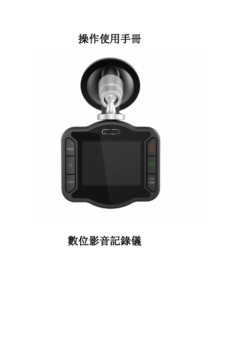
操作使用手冊數位影音記錄儀目錄前言………………………………………………産品特點…………………………………………產品結構…………………………………………操作說明…………………………………………菜單設置…………………………………………指示燈狀態圖……………………………………産品參數…………………………………………前言非常感謝您購買數位影音記錄儀。
本產品是針對現今行車事故取證難專門研發的一款產品;同時也滿足其他場合使用的需求,可運用於會議記錄、監控取證、外景拍攝、取證攝像等,能讓您一機多用,讓您的生活無憂,更加豐富多彩。
本產品融合了行業領先的數碼攝像、語音存儲、網絡攝像頭、自帶顯示屏實時回放、移動偵測錄像等技術於一體。
獨特的流線型設計,深受廣大顧客的青睞,並已獲得外觀專利。
本手冊將詳細說明如何安裝、操作、產品參數和注意事項等。
使用前請詳細閱讀並請妥善保管,我們希望本產品能滿足您的需求並長期服務於您!产品特点>獨特的外觀設計,並獲得外觀專利>低照度,130W高清攝像頭>機器自帶2.5寸顯示屏,可邊錄邊看和隨時實時回放>視頻輸出:1280*960,640*480,320*240三種可選>超寬120度廣角鏡頭>內置950毫安鋰電池,可支持3-4小時持續錄像,移動偵測更可延長待機時間>循環錄影,記錄最新最美的一刻>支援上電自動開始錄影,操作更加方便>使用TF記憶卡儲存錄影檔案,可支援1G-32G>支持多國語言菜單:中文簡體,中文繁體,英文,葡萄牙語,西班牙語,日語,俄語,意大利語,法語和德語>供電錄影功能,可以邊開車邊錄,或者邊充電邊錄像。
>支持有聲和無聲錄像>PC攝像功能,隨時隨地與家人共享生活產品結構操作說明1.插入TF卡,可支援卡容量大小為1G-32G。
2.將記錄儀與標配的車充連接,再與車的點煙口連接。
3.錄像(1)手動錄像:短按ON/OFF鍵,記錄儀會發出嗶聲,藍色指示燈亮,然後會自動開始錄像,藍燈慢閃。
DVD SACD玩家快速使用指南说明书
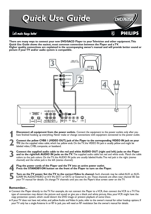
D VD763SAelevision and other equipment.Thismost common connection between the Player and a TV.Higher quality connections are explained in the accompanying owner’s manual and will provide better sound orST ANDBY -ONSMART PICTURE SOUNDOPEN/CLOSE PLAY/PAUSEOKPREV NEXT STOPDVD 763SA DVD VIDEO/SACD PLAYERMENU3-41T o simply play a Disc,follow these steps.Additional playback features are described in the accompanying owner’s manual.1Press STANDBY -ON on the front of the Player to turn on the Player.2T urn on your TV .Set it to the correct Video In channel.Y ou should see the Player ’s blue screen saver on the TV (if no Disc is in the Player).3Press OPEN/CLOSE on the front of the Player to open the disc tray.4Load your Disc in the tray ,with the label facing up.If the Disc (DVD) is two-sided,make sure the side you want to play is facing up.Press OPEN/CLOSE again to close the tray.5Playback may start automatically.If not,press PLAY B .If a Disc menu appears,use the 1234and OK buttons or the Number buttons to select features or start playback from a menu.Follow the instructions in the Disc menu.6T o stop playing the Disc,press STOP 9.Region CodesDVDs must be labeled for ALL regions or for Region 1 in order to play on this Player.Y ou cannot play Discs that are labeled for other regions.If one of these logos appears on your DVD or its case,it should play on this Player.Color SystemsRecordings are made according to a color system.The most common color system in the United States is NTSC.This Player is compatible with NTSC and PAL.Make sure the Discs you play were recorded in NTSC or PAL and your TV is NTSC or PAL compatible.Look for the color system of the DVD on the DVD or on the Disc case.Playable DiscsThis Player will play the following types of Discs:DVD(Digital Video Disc)Super Audio CD (Compact Disc Digital Super Audio)MP3FilesAudio CD (Compact Disc Digital Audio)Video CDSuper Video CDCD-R (CD-Recordable)CD-RW (CD-Rewritable)1234567809POWERREPEAT SHUFFLE SCANREPEAT A-BSTOPDISPLAYRETURNDISC SYSTEMANGLEZOOMAUDIOSUBTITLEPLAYPAUSEFTST-CDIMSOUND MODEMENU MENUÉÉÉÉOKGÇÉÅH256NTSCPALQuick Use Guide (cont’d)RecordableReWritable。
写碟机(STW)操作及维护规程

开始擦伺服 信号的轨道
编号
开始写伺 服信号的 轨道编号
结束写伺 服信 号的轨道编号
对应 Project 的 TrackPitch 值
4.6 写碟完成后,通过示波器查看所写的伺服信号。
按 F1 键,进入 Setup 菜单,在提示对话框内输入 3 按回车键,然后再按 F3 键进入 Read/Write 菜单,通过在提示对话框内输入 1 和 14,并按回车键来对所写碟片的轨道和碟 片进行查看,一般选择的轨道为伺服信号所写区域的中间位置,因为该位置较为靠近动态测 试中的测试位置。当所查看的伺服信号没有问题时, Rotary 回初始位置(按 F1 键,进入 Setup 菜单,在提示对话框内输入 13 按回车键),并取下碟片放到碟罐内。然后按照 4.4 至 4.6 的 步骤开始写新的碟片。若通过示波器所查看的伺服信号有问题,写碟机操作员工应迅速通知 相关的 TE 工程师,直至问题解决才能重新开始写碟。
当前进入的为 Setup 菜单
自动加载 当前进入 的为 Setup 菜单
键入 3 后回 车,进 行自动 加载
自动回初始位置
当前进入的为Read/Wr ite菜单
在Keybo ardInput 框内输入1回车,然 后在该框内输入要 查看伺服信号的轨 道编号回车,即可 对该轨道进行信号
查看
当前查看信号 的磁头编号
1.STW 组成介绍
磁头臂组合(HGA)或者磁头(Slider)的动态性能(Dynamic Performance)测试需要在已经 写上伺服信号的碟片上的某一条确定轨道上进行,而普通的动态测试机自身并不具备往碟片 上写伺服信号的能力,因而需要专门的设备——写碟机(STW)来完成这一功能。
写碟机(STW)由硬件(具体组成如图所示)和软件两部分组成。硬件部分主要包括 Canon 的 Rotary Spinstand(RS-5820U/BT),SPIC2004A 控制箱。软件部分主要由 DOS 操作系统, STW 运行控制程序和 Rotary 走位控制程序组成。而且还包括必要的外设如 LCD 显示器和 PS/2 键盘。
铭记刑刻机用户手册说明书

Troubleshooting the Zing EngraverRevision: Mar. 12, 15Please be sure that the engraver is powered OFF before performing any of theprocedures outlined in this document.Y Axis Too Far Forward on BootIf the Y Axis of the Engraver begins too far forward, or does not go all the way to the back of the engraver during the boot process, it is likely that the Home Position Sensor is blocked by debris. To clear the debris, locate the sensor unit on the Right hand side of the Rail and direct Compressed Air into the Y-Axis position sensor slot.X Axis Makes Grinding Noise on BootIf the X-Axis of the Engraver reaches the left hand side of the Rail and makes a grinding noise, or does not go all the way to the right hand side of the engraver during the boot process, it is likely that the Home Position Sensor is blocked by debris. To clear the debris, locate the sensor unit on the Right hand side of the Rail and direct Compressed Air into the X-Axis position sensor slot.X Axis Skewing and SlantingIf the user is experiencing ‘Slanting’, ‘Skewing’, ‘Waviness’, ‘Stair Stepping’ or ‘Losing Home’ during an engraving operation, it is likely that the belt has lost tension. Remove the Left hand side cover of the engraver and activate the Automatic Belt Tensioner on the right hand end of the Rail.If the belt tension does not completely address the issue, the belt may be worn and will require replacement.Double ImageHorizontalIf the user is experiencing ‘Double Image’ or ‘Ghost Images’ where the images are directly horizontal from each other, it is likely that the belt has lost tension. Remove the Left hand side cover of the engraver and activate the Automatic Belt Tensioner on the right hand end of the Rail.If the belt tension does not completely address the issue, the belt may be worn and will require replacement.VerticalVertical double imaging can come from lens carriage not rolling straight in the track on the rail. Attempt to re-seat the lens carriage rollers back into the roller tracks. If that does not fix the issue, remove the Lens Carriage from the engraver and inspect each of the carriage roller bearings for flat spots. Replace any suspect rollers.DiagonalIf the images positioned are diagonally from each other it is likely a problem with one of the engravers Optics. Start by checking for Scratches or Cracks in any of the optics. If Optic damage can be eliminated, check for Optic Stability. Make sure that all of the optic bezels for the Lens and Carriage Mirror are threaded properly and screwed in tight. Check for any excess vibration in the movement of the Rail, lens carriage or belts and be sure that the Mirrors on the Left side of the engraver are mounted properly and are not loose.Laser Cuts OutThe most likely cause for a laser to cut out is a loose or vibrating interlock. Begin checking the interlocks by opening the top door of the engraver and checking to be sure that both of the silver Interlock Magnets are still in place and are not loose. Next check the interlock sensors under the edge of the door opening of the engraver. Make sure that both sensors are screwed in place and stable. Check Interlock LED on the Right side of the engraver, it should illuminate when the door is closed.The next likely reason for laser fire to cut out during operation is Overheating. Start by ensuring that the left side of the engraver is clear of obstructions. The Zing engraver exhausts hot air from the laser tube out of the bottom of the left side panel. In order to cool properly there must be no obstructions on the left side of the engraver for 12 to 24 inches.After insuring that the engraver can exhaust hot air, check that the Heat Sinks on the Laser Tube are not clogged with debris. Open the left side panel and direct air at the Heat Sinks (‘fins’) on the laser tube until they are clear of debris.If after clearing the side and heat sinks of debris and obstructions the laser is still cutting out, remove the rear panel on the engraver and locate the Fan Control Board. Flip the switch on the fan control board to “Override”. Power on the engraver and allow sitting for 15 minutes. If the laser no longer cuts out, the fan control board may be malfunctioning and should be replaced.Fuzzy EngravingHorizontalThe engraver is comes calibrated from the factory for resolutions of 500 DPI. If the user is using a lower resolution, try the engraving again at 500 DPI. If changing the DPI does not fix the issue engrave a 1” x 1” filled raster square. Measure the width of the square (fuzzy area included). Increase the Laser Matchsetting in the Configuration menu by 1. Resend and measure the square again. If the square has increased in width, laser match must be decreased. If the square has increased in width the laser match must be increased. Repeat until the fuzziness has gone away and the square is exactly at 1”.If you are unable to eliminate fuzziness with the laser match setting, the laser tube may need to be replaced.GeneralGeneral fuzziness comes from vibration. Make sure that all of the optic bezels for the Lens and Carriage Mirror are threaded properly and screwed in tight. Check for any excess vibration in the movement of the Rail, lens carriage or belts and be sure that the Mirrors on the Left side of the engraver are mounted properly and are not loose.。
高清审讯主机用户快速使用手册

高清审讯主机快速使用手册天津天地伟业数码科技有限公司设备外观接插示意图型号1:TC-H804N-HD-P型号2:TC-H804I-HD-BP1. 基本操作指南1.开机提醒:请确认接入的直流电压与高清审讯主机的要求相匹配,并保证主机电源插座中间接地端接地良好。
2.切换用户开机后,系统自动使用“default”用户登录,“default”用户的权限较低,仅可浏览视频。
系统默认账号是“Admin”,初始密码是“1111”。
1.3 预览设置登录后用户希望设置预览模式时可以点击“右键”=>“预览设置”来设置,在预览模式中可以选择各种画面模式,然后点击“自动配置”即可。
1.4 配置IP地址登录后点击鼠标右键弹出【快捷菜单】=>【主菜单】=>【系统设置】=>【网络设置】。
如下图,默认打开网络设置显示网卡1界面,可对IP地址进行配置,网卡1默认IP是“192.168.001.002”。
选择常规设置选项,分别设置IP地址和DNS,IP地址和DNS设置与windows的网络设置类似,如果您不清楚您所在网络的IP地址,请咨询网络管理员。
1.5 安装浏览器客户端并登陆点击浏览器图标后点击【工具】=>【Internet选项】在安全设置中,把下载未签名的ActiveX控件,选定为启用(如下图所示)在可信任的站点中输入相应的IP地址。
在本地PC浏览器中输入已经设置的设备IP地址,会弹出如下提示点击“安装”,等待数秒钟,就会弹出登陆界面默认的用户名为“Admin”,密码是“1111”,端口号“3000”1.6 添加设备在左侧设备树中右键点击,选择“添加设备”,会弹出如下提示输入相应的IP地址,用户名和密码,即可添加。
1.7 加载合成画面在设备树中,双击通道5,即可显示合成画面图像1.8 合成通道参数设置单击选中设备树中的设备=>单击参数配置,即可配置混音,视频参数,字符叠加等配置1.9 安全关机按下前面板的电源按钮,并在弹出的对话框中点击“确定”,等待提示消失后断开电源。
高清数字X射线系统 操作手册 全文-(校对排版)(纯中文)
福建省科学器材进出口公司ES3-8-320型B版EnvisionScan™高清数字X射线系统S/N EPD121116-ES制造年月:2011年7月1.0版手册2011年7月15日Envision CmosXray有限责任公司Anchorage, AK 99518国王大街7800号电话:907-563-1141传真:907-563-1142Email: info@网址:©Envision, 2010依照版权法规定,未经Envision产品设计公司明确书面许可,任何人不得基于任何目的对本手册进行复制、传阅、抄写或存入检索系统,或以任何电子或机械形式或方式将其翻译为任何语言。
EnvisionScan系Envision产品设计公司商标。
本指南相关信息如有变更,恕不另行通知。
注意与EnvisionScan™系统配合使用的设备可产生有害辐射,必须由具备资格的专业人员进行操作,且操作人员必须在操作前阅读本手册“警告”部分。
Envision产品设计公司不对因缺乏培训和EnvisionScan系统操作过程中的不当使用或危险做法导致的设备损坏承担任何责任。
本设备不得故意用于人体接触或用作医学X射线摄影,否则可构成违法行为。
警告管材控制程序运行过程中,任何人员不得靠近管材运动系统,否则可导致人员伤亡事故。
保养作业前务必确保无人靠近运动部件且系统已停止运行并锁闭,同时确保操作人员不会受到管材或运动的小车的撞击或压伤。
警告为确保本产品的正确运行和使用,请务必阅读并完全理解本用户手册。
手册内容包括安装、启动、操作和故障检修程序。
EnvisionScan™系统采用传统X射线管,可能产生辐射危险。
本设备不得故意用于人体接触或用作医学X射线摄影,否则可构成违法行为。
EnvisionScan™系统的操作须遵守国家法规并进行注册。
设备操作前请联系国家卫生部门。
EnvisionScan™系统操作人员必须在操作前接受适当的辐射安全培训。
大华审询主机说明书
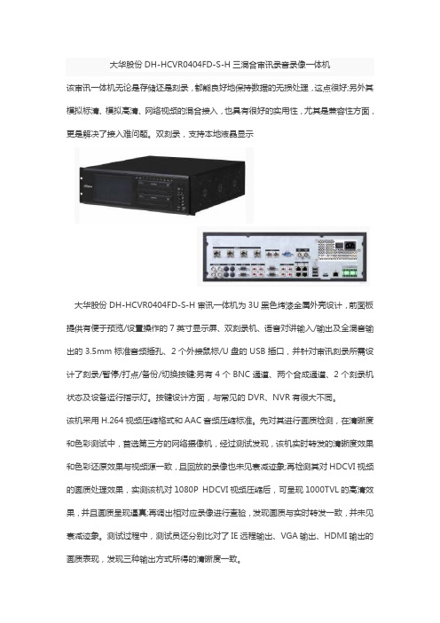
大华股份DH-HCVR0404FD-S-H三混合审讯录音录像一体机该审讯一体机无论是存储还是刻录,都能良好地保持数据的无损处理,这点很好;另外其模拟标清、模拟高清、网络视频的混合接入,也具有很好的实用性,尤其是兼容性方面,更是解决了接入难问题。
双刻录,支持本地液晶显示大华股份DH-HCVR0404FD-S-H审讯一体机为3U黑色烤漆金属外壳设计,前面板提供有便于预览/设置操作的7英寸显示屏、双刻录机、语音对讲输入/输出及全混音输出的3.5mm标准音频插孔、2个外接鼠标/U盘的USB插口,并针对审讯刻录所需设计了刻录/暂停/打点/备份/切换按键;另有4个BNC通道、两个合成通道、2个刻录机状态及设备运行指示灯。
按键设计方面,与常见的DVR、NVR有很大不同。
该机采用H.264视频压缩格式和AAC音频压缩标准。
先对其进行画质检测,在清晰度和色彩测试中,首选第三方的网络摄像机,经过测试发现,该机实时转发的清晰度效果和色彩还原效果与视频源一致,且回放的录像也未见衰减迹象;再检测其对HDCVI视频的画质处理效果,实测该机对1080P HDCVI视频压缩后,可呈现1000TVL的高清效果,并且画质呈现逼真;再调出相对应录像进行查验,发现画质与实时转发一致,并未见衰减迹象。
测试过程中,测试员还分别比对了IE远程输出、VGA输出、HDMI输出的画质表现,发现三种输出方式所得的清晰度一致。
在该机的本地客户端中我们发现,该机的菜单新增两项设计:一是设置菜单中的“审讯”,此处主要是进行审讯应用中的音视频配置,包括音频矩阵、音量调节、合成通道和预案配置;其中合成通道提供有支持1、2、3、4、5、6、8画面和画中画等8种模式可选,可从视频源中任选n路进行画面分割或通道叠加,利于有效地观察审讯中的所有场景。
另一个就是操作菜单中的“审讯”,该处主要进行光盘刻录操作,包括给光盘刻录加密、添加水印等安全措施设置,同时能给刻录视频叠加案件编号、主审官、原被告等OSD 信息,还提供有进行快速查找案件功能。
- 1、下载文档前请自行甄别文档内容的完整性,平台不提供额外的编辑、内容补充、找答案等附加服务。
- 2、"仅部分预览"的文档,不可在线预览部分如存在完整性等问题,可反馈申请退款(可完整预览的文档不适用该条件!)。
- 3、如文档侵犯您的权益,请联系客服反馈,我们会尽快为您处理(人工客服工作时间:9:00-18:30)。
AVST-X3标清移动审讯光盘直刻终端说明书
应用范围
AVST-X3主要适用于公安、检察、纪委、海关、安全等部门移动审讯办案需求,可在非固定式审讯室中快速安装布置,完全能够满足同步录音录像标准要求,并可作为固定同步录音录像设备的备份手段。
功能特点
◆双光盘实时同步直刻
◆视频文件唯一哈希值
◆高清采集(HDMI、VGA输入)
◆支持断电光盘保护与数据恢复
◆音频信号动态可视化
◆通用播放器可以播放,方便示证使用
◆设备可灵活调整显示内容的背景、颜色、位置、显示停留时间等
◆支持案件、光驱状态、硬盘、温湿度等信息叠加
◆可快速出盘,出盘时间不大于1分钟
◆远程提审功能,具备视频会议终端通H.323协议,可以与视频会议终端直接呼叫通讯
技术参数
连接图。
