MOCD223中文资料
M223资料
• North America Tel: 800.366.2266 / Fax: 978.366.2266 • Europe Tel: 44.1908.574.200 / Fax: 44.1908.574.300 • Asia/Pacific Tel: 81.44.844.8296 / Fax: 81.44.844.8298 Visit for additional data sheets and product information.
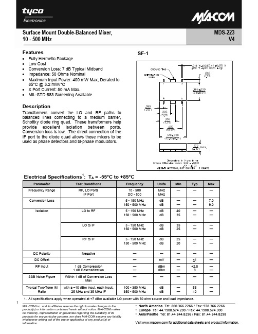
Surface Mount Double-Balanced Mixer, 10 - 500 MHz
Features
Fully Hermetic Package Low Cost Conversion Loss: 7 dB Typical Midband Impedance: 50 Ohms Nominal Maximum Input Power: 400 mW Max, Derated to 85°C @ 3.2 mW/°C • X Port Current: 50 mA Max. • MIL-STD-883 Screening Available • • • • •
.220 .165
4X .099 ± .010 .381
.002 .000
.367
.143
.080
.205mation
Part Number MDS-223 PIN Package SF-1
Pin Configuration
Pin No. 1 2 Function GND IF Pin No. 3 4 Function LO RF
1. All specifications apply when operated at +7 dBm available LO power with 50 ohm source and load impedance.
MOC中文资料
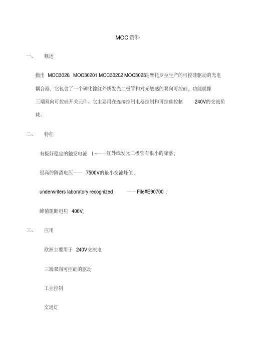
MOC资料一、概述摸出MOC3020 、MOC30201、MOC30202、MOC3023是摩托罗拉生产的可控硅驱动的光电耦合器,它包含了一个砷化镓红外线发光二极管和对光敏感的双向可控硅,功能就像三端双向可控硅开关元件。
它主要用在连接控制电器控制和可控硅控制240V的交流负载。
二、特征有极好稳定的触发电流I FT——红外线发光二极管有很小的降落;很高的隔离电压——7500V的最小交流峰值;underwriters laboratory recognized——File#E90700;峰值阻断电压400V;三、应用欧洲主要用于240V交流电三端双向可控硅的驱动工业控制交通灯自动售货机电动机控制固态继电器在空气温度25摄氏度时的绝对最大额定值:储存温度范围:-40°——150°工作温度范围:-40°——100°二极管输入正向直流电流:50mA二极管输入反向电压:3V二极管输入峰值正向电流:3A(1um的脉冲,每秒300脉冲)二极管输入的功率耗散:100mw(25摄氏度左右)线性递减(25°左右):1.33mw/o C输出驱动:输出断开的终端电压:400V输出接通的均方根电流:(T A=25°)100mA(50HZ—60HZ正弦波) (T A=70°) 50mA抽象峰值浪涌电流: 1.2A(T w=10ms空比DC=10%)总的功率损耗:300mw四、元件特性特性符号最小典型最大单位测试条件正向电压V F 1.2 1.5V I F=10mA结电容C J50pF V F=0 f=1MHZ 反向漏电流I R0.05100uA V R=3.0V峰值阻断电流I DRM10100nA V DRM=400V dv/dt≤12V/us峰值接通电压V TM 2.5 3.0V I TM=100mA peak直流触发电流I FT815mA供给电压=3VR L=150保持电流I H100uA。
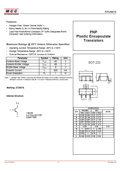
MCCSEMI PZT2907A SOT-223电极热感应器电路芯(PNP)膨胀封装透明电阻说明书
&RXQWHUIHLWLQJ RIVHPLFRQGXFWRUSDUWVLVDJURZLQJ SUREOHP LQWKHLQGXVWU\0LFUR&RPPHUFLDO &RPSRQHQWV 0&& LVWDNLQJ VWURQJPHDVXUHVWRSURWHFWRXUVHOYHVDQGRXUFXVWRPHUVIURPWKHSUROLIHUDWLRQRIFRXQWHUIHLWSDUWV0&&VWURQJO\HQFRXUDJHV FXVWRPHUVWRSXUFKDVH0&&SDUWVHLWKHUGLUHFWO\IURP0&&RUIURP$XWKRUL]HG0&&'LVWULEXWRUVZKRDUHOLVWHGE\FRXQWU\RQ RXUZHESDJHFLWHGEHORZ3URGXFWVFXVWRPHUVEX\HLWKHUIURP0&&GLUHFWO\RUIURP$XWKRUL]HG0&&'LVWULEXWRUVDUHJHQXLQH SDUWV KDYH IXOO WUDFHDELOLW\ PHHW 0&&
Parameter Collector-Base Voltage Collector-Emitter Voltage Emitter-Base Voltage Collector Current Power Dissipation
Symbol
VCBO VCEO VEBO
IC PD
Rating -60 -60 -5 -600 1
-0.4
Collector-Emitter Saturation Voltage VCE(sat)
MAX232中文资料,MAX232CPE,MAX232EPE,MAX232ECPE,规格书,MAXIM代理商,datasheet,PDF
19-4323; Rev 15; 13;5V ޥ٫Ăۂ لRS-232 ഝڑಹ/ेฏಹ
________________________________ ݣะ
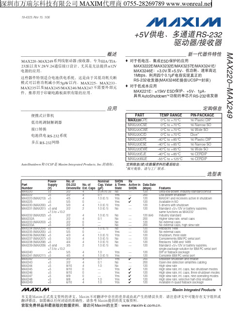
MAX220–MAX249࿅઼ഝڑಹ /ेฏಹLjከཛྷEIA/TIA232EჾࣆV.28/V.24ဳेਊහࣜLjᅐದกྐۨ໗ ޥ±12V ٫ᆚوᄮᅋă
ሦဗಹऔ໎Ӽคࠩ٫֠ޥ٫࿅༇Ljሦกᅑᅢದّڱߔࠞޢ ன৹ჾटࠞޢऋဏ ف5μW ჾăMAX225ĂMAX233Ă MAX235 ჾࣆ MAX245/MAX246/MAX247 ԥၖე༶ԩᆐ औLj༚ऌᅋᅢᄩฺ٫ଁғஎࢵᅘوᄮᅋă
1.0 (0.1) 0.1 — — 1.0 (0.1) — 1.0 (0.1) 1.0 (0.1) 1.0 (0.1) 1.0 (0.1)
1.0 1.0 (0.1) 0.1 0.1 1.0 — — — 1.0 1.0
SHDN & ThreeState No Yes Yes Yes Yes No
No No No No No Yes Yes No No No
_____________________________________________________________________ ၭျӹ
Part Number MAX220 MAX222 MAX223 (MAX213) MAX225 MAX230 (MAX200) MAX231 (MAX201)
MAX232 (MAX202) MAX232A MAX233 (MAX203) MAX233A MAX234 (MAX204) MAX235 (MAX205) MAX236 (MAX206) MAX237 (MAX207) MAX238 (MAX208) MAX239 (MAX209)
SOT223中文资料

SMT-Precision-R-Networks Type: SCNSizes: SOT 143, SOT 223, SO 8, SO 14, SO 16, SO 20LFeatures:• Thinfilm (NiCr) on passivated Si- or Alumina-substrate • Standard types and custom networks• Relative-data (tolerance, TCR and stability) much closer than with single resistorsSizes: ExampleL = Length, B = Width, D = Thickness, C = Width wrap around (in mm) (detailed drawings on request)Standard versions:Resistor bridges, single resistors and current-divider (detailed data on request)Inquiry and ordering data: SizeNumber and connection of resistors Resistance valuesTolerance and TCR (absolute and relative) Power ratingTemperature range Stability requirementsPackaging (bulk, tape/reel, magazine)Size L B D n SOT 143 3.0 2.5 1.1 4 SOT 223 6.5 7.0 1.6 4 SO 8 5.1 6.0 2.0 8 SO 14 8.9 6.0 2.0 14 SO 1610.26.02.016SO 20L 13.0 10.5 2.65 20Willow Technologies Ltd. Shawlands Court, Newchapel Road, Lingfield, Surrey, RH7 6BL, United KingdomTel . + 44 (0) 1342 835234 Fax. + 44 (0) 1342 834306 E-Mail.sales@ Web. SMT-Precision-R-Networks Type: SCNSizes: SOT 143, SOT 223, SO 8, SO 14, SO 16, SO 20LTechnical data – depending on sizeSizeSOT 143SOT 223SO 8So 14SO 16SO 20LPower rating P 70 (P 125 = 0 mW) 125 250 250 250 250 500 Resistance range10R / 1M10R / 5M10R / 5M10R / 10M10R / 10M10R / 10MTechnical data - general:Working voltage U_, U eff 100 V Silizium, 250 V Keramik Tolerance absolute relative± 0.05; ± 0.1; ± 0.25; ± 0.5; ± 1% < 0.0251) ; < 0.05; < 0.1%TCR absolute relative± 51), ± 102), ± 25, ± 50, x 10-6/K < 11), < 22), < 5, < 10-6/KOperating temperature range - 55°C ... + 125°C Storage temperature range- 55°C ... + 155°C Climatic category acc. to IEC 6006825/125/56Solderability IEC 60068 T2-20, Ta Meth. 1 235°C 2s Max. soldering temperature IEC 60068 T2-20, Tb Meth. 1A 260°C 10sLong term stability Tol.< 0.25%Tol.> 0.25%1000 h 10000 h 1000 h 10000 h Storage 125°C/1000h absolute relative < 0.02% < 0.005% < 0.06% < 0.02% < 0.05% < 0.01% < 0.1% < 0.05% Storage 155°C/1000h absolute relative < 0.1% < 0.05%< 0.2% < 0.1% < 0.2% < 0.1%< 0.5% < 0.2% Damp heat absolute (56d/40°C/96%) relative< 0.05% < 0.01%< 0.10% < 0.05%1) Temperature range 0 … + 70°C 2)Temperature range –25 … + 125°CIssue 01/03 Willow Technologies Ltd. Shawlands Court, Newchapel Road, Lingfield, Surrey, RH7 6BL, United Kingdom Tel . + 44 (0) 1342 835234 Fax. + 44 (0) 1342 834306 E-Mail.sales@ Web. 。
PRO Series LCD Monitor PRO MP223 (3PB9) 用户指南说明书

PRO Series LCD Monitor PRO MP223 (3PB9)User GuideContentsGetting Started (3)Package Contents (3)Installing the Monitor Stand (4)Adjusting the Monitor (5)Monitor Overview (6)Connecting the Monitor to PC (8)OSD Setup (9)OSD Keys (9)OSD Menus (11)Professional (11)Image (13)Input Source (14)Navi Key (15)Setting (15)Specifications (17)Preset Display Modes (19)Troubleshooting (20)Safety Instructions (21)TÜV Rheinland Certification (23)Regulatory Notices (24)RevisionV1.0, 2023/032ContentsGetting StartedThis chapter provides you with the information on hardware setup procedures. While connecting devices, be careful in holding the devices and use a grounded wrist strap to avoid static electricity.∙Contact your place of purchase or local distributor if any of the items is damaged or missing.∙Package contents may vary by country.∙The included power cord is exclusively for this monitor and should not be used with other products.3Getting StartedInstalling the Monitor Stand1. Leave the monitor in its protective foam packaging. Align and gently push the stand bracket towards the monitor groove until it locks in place.2. Align and gently push the cable organizer towards the stand until it locks in place.3. Align and gently push the base towards the stand until it locks in place.4. Make sure the stand assembly is properly installed before setting the monitor Array∙Place the monitor on a soft, protected surface to avoid scratching the display panel.∙Do not use any sharp objects on the panel.∙This product comes with NO protective film to be removed by the user! Anymechanical damages to the product including removal of the polarizing film mayAdjusting the MonitorThis monitor is designed to maximize your viewing comfort with its adjustment capabilities.⚠ImportantAvoid touching the display panel when adjusting the monitor.5Getting StartedMonitor Overview6Getting Started7 Getting StartedConnecting the Monitor to PC1. Turn off your computer.2. Connect the video cable from the monitor to your computer.3. Assemble the external power supply & power cord. (Figure A)4. Connect the external power supply to the monitor power jack. (Figure B)5. Plug the power cord into the electrical outlet. (Figure C)6. Turn on the monitor. (Figure D)7. Power on the computer and the monitor will auto detect the signal source.8Getting StartedOSD Setup⚠ImportantThis chapter provides you with essential information on OSD Setup.All information is subject to change without prior notice.OSD KeysThe monitor comes with a set of OSD Keys that help to control the On-Screen Display (OSD) menu.9OSD Setup10OSD Setup11OSD MenusPress the M key to launch the On-Screen Display (OSD) main menu and use the OSD keys to tune the desired function to suit your personal preferences.12OSD Menus13 OSD Menus14OSD Menus15 OSD Menus16OSD Menus12V12V17Specifications18Specifications* Based on CIE1976 test standards.Preset Display ModesImportant19Preset Display ModesTroubleshootingThe power LED is off.• Press the monitor power button again.• Check if the monitor power cable is properly connected.No image.• Check if the computer graphics card is properly installed.• Check if the computer and monitor are connected to electrical outlets and areturned on.• Check if the monitor signal cable is properly connected.• The computer may be in Standby mode. Press any key to activate the monitor. The screen image is not properly sized or centered.• Refer to Preset Display Modes to set the computer to a setting suitable for themonitor to display.No Plug & Play.• Check if the monitor power cable is properly connected.• Check if the monitor signal cable is properly connected.• Check if the computer and graphics card are Plug & Play compatible. The icons, font or screen are fuzzy, blurry or have color problems.• Avoid using any video extension cables.• Adjust brightness and contrast.• Adjust RGB color or tune color temperature.• Check if the monitor signal cable is properly connected.• Check for bent pins on the signal cable connector.The monitor starts flickering or shows waves.• Change the refresh rate to match the capabilities of your monitor.• Update your graphics card drivers.• Keep the monitor away from electrical devices that may cause electromagneticinterference (EMI).20TroubleshootingSafety Instructions∙Read the safety instructions carefully and thoroughly.∙All cautions and warnings on the device or User Guide should be noted.∙Refer servicing to qualified personnel only.Power∙Make sure that the power voltage is within its safety range and has been adjusted properly to the value of 100~240V before connecting the device to the power outlet. ∙If the power cord comes with a 3-pin plug, do not disable the protective earth pin from the plug. The device must be connected to an earthed mains socket-outlet.∙Please confirm the power distribution system in the installation site shall provide the circuit breaker rated 120/240V, 20A (maximum).∙Always disconnect the power cord or switch the wall socket off if the device would be left unused for a certain time to achieve zero energy consumption.∙Place the power cord in a way that people are unlikely to step on it. Do not place anything on the power cord.∙If this device comes with an adapter, use only the MSI provided AC adapter approved for use with this device.BatteryPlease take special precautions if this device comes with a battery.∙Danger of explosion if battery is incorrectly replaced. Replace only with the same or equivalent type recommended by the manufacturer.∙Avoid disposal of a battery into fire or a hot oven, or mechanically crushing or cutting of a battery, which can result in an explosion.∙Avoid leaving a battery in an extremely high temperature or extremely low air pressure environment that can result in an explosion or the leakage of flammable liquid or gas.∙Do not ingest battery. If the coin/button cell battery is swallowed, it can cause severe internal burns and can lead to death. Keep new and used batteries away from children.European Union:Batteries, battery packs, and accumulators should not be disposed of asunsorted household waste. Please use the public collection system toreturn, recycle, or treat them in compliance with the local regulations. BSMI:廢電池請回收For better environmental protection, waste batteries should be collectedseparately for recycling or special disposal.21Safety InstructionsCalifornia, USA:The button cell battery may contain perchlorate material and requiresspecial handling when recycled or disposed of in California.For further information please visit: https:///perchlorate/ Environment∙To reduce the possibility of heat-related injuries or of overheating the device, do not place the device on a soft, unsteady surface or obstruct its air ventilators.∙Use this device only on a hard, flat and steady surface.∙To prevent the device from tipping over, secure the device to a desk, wall or fixedobject with an anti-tip fastener that helps to properly support the device and keep it safe in place.∙To prevent fire or shock hazard, keep this device away from humidity and hightemperature.∙Do not leave the device in an unconditioned environment with a storage temperature above 60℃ or below -20℃, which may damage the device.∙The maximum operating temperature is around 40℃.∙When cleaning the device, be sure to remove the power plug. Use a piece of softcloth rather than industrial chemical to clean the device. Never pour any liquid into the opening; that could damage the device or cause electric shock.∙Always keep strong magnetic or electrical objects away from the device.∙If any of the following situations arises, get the device checked by service personnel:• The power cord or plug is damaged.• Liquid has penetrated into the device.• The device has been exposed to moisture.• The device does not work well or you can not get it working according to the UserGuide.• The device has dropped and damaged.• The device has obvious sign of breakage.22Safety InstructionsTÜV Rheinland CertificationTÜV Rheinland Low Blue Light CertificationBlue light has been shown to cause eye fatigueand discomfort. MSI now offers monitors with TÜVRheinland Low Blue Light certification to ensureusers’ eye comfort and well-being. Please followthe instructions below to reduce the symptoms fromextended exposure to the screen and blue light.∙Place the screen 20 – 28 inches (50 – 70 cm) away from your eyes and a little below eye level.∙Consciously blinking the eyes every now and then will help to reduce eye strain after extended screen time.∙Take breaks for 20 minutes every 2 hours.∙Look away from the screen and gaze at a distant object for at least 20 seconds during breaks.∙Make stretches to relieve body fatigue or pain during breaks.∙Turn on the optional Low Blue Light function.TÜV Rheinland Flicker Free Certification∙TÜV Rheinland has tested this product toascertain whether the display produces visibleand invisible flicker for the human eye andtherefore strains the eyes of users.∙TÜV Rheinland has defined a catalogue oftests, which sets out minimum standardsat various frequency ranges. The test catalogue is based on internationally applicable standards or standards common within the industry and exceeds these requirements.∙The product has been tested in the laboratory according to these criteria.∙The keyword “Flicker Free” confirms that the device has no visible and invisible flicker defined in this standard within the range of 0 - 3000 Hz under various brightness settings.∙The display will not support Flicker Free when Anti Motion Blur/MPRT is enabled. (The availability of Anti Motion Blur/MPRT varies by products.)23TÜV Rheinland CertificationRegulatory NoticesCE ConformityThis device complies with the requirements set out in the Council Directive on the Approximation of the Laws of the Member States relating to Electromagnetic Compatibility (2014/30/EU), Low-voltage Directive (2014/35/EU), ErP Directive (2009/125/EC) and RoHS directive (2011/65/EU). This product has been tested and found to comply with the harmonized standards for Information Technology Equipment published under Directives of Official Journal of the European Union.FCC-B Radio Frequency Interference StatementThis equipment has been tested and found to comply with the limitsfor a Class B digital device, pursuant to Part 15 of the FCC Rules.These limits are designed to provide reasonable protection against harmful interference in a residential installation. This equipment generates, uses and can radiate radio frequency energy and, ifnot installed and used in accordance with the instruction manual, may cause harmful interference to radio communications. However, there is no guarantee that interference will not occur in a particular installation. If this equipment does cause harmful interference to radio or television reception, which can be determined by turning the equipment off and on, the user is encouraged to try to correct the interference by one or more of the measures listed below:∙Reorient or relocate the receiving antenna.∙Increase the separation between the equipment and receiver.∙Connect the equipment into an outlet on a circuit different from that to which thereceiver is connected.∙Consult the dealer or an experienced radio/television technician for help. Notice 1The changes or modifications not expressly approved by the party responsible for compliance could void the user’s authority to operate the equipment. Notice 2Shielded interface cables and AC power cord, if any, must be used in order to comply with the emission limits.This device complies with Part 15 of the FCC Rules. Operation is subject to the following two conditions:1. This device may not cause harmful interference, and2. This device must accept any interference received, including interference that maycause undesired operation.MSI Computer Corp.901 Canada Court, City of Industry, CA 91748, USA(626) 913-082824Regulatory NoticesWEEE StatementUnder the European Union (“EU”) Directive on Waste Electrical and Electronic Equipment, Directive 2012/19/EU, products of “electrical and electronic equipment” cannot be discarded as municipal waste anymoreand manufacturers of covered electronic equipment will be obligated totake back such products at the end of their useful life. Chemical Substances InformationIn compliance with chemical substances regulations, such as the EU REACH Regulation (Regulation EC No. 1907/2006 of the European Parliament and the Council), MSI provides the information of chemical substances in products at: https:///global/indexRoHS StatementJapan JIS C 0950 Material DeclarationA Japanese regulatory requirement, defined by specification JIS C 0950, mandates that manufacturers provide material declarations for certain categories of electronic products offered for sale after July 1, 2006.https:///global/Japan-JIS-C-0950-Material-DeclarationsIndia RoHSThis product complies with the “India E-waste (Management and Handling) Rule 2016” and prohibits use of lead, mercury, hexavalent chromium, polybrominated biphenylsor polybrominated diphenyl ethers in concentrations exceeding 0.1 weight % and 0.01 weight % for cadmium, except for the exemptions set in Schedule 2 of the Rule. Turkey EEE RegulationConforms to the EEE Regulations of the Republic Of TurkeyUkraine Restriction of Hazardous SubstancesThe equipment complies with requirements of the Technical Regulation, approved by the Resolution of Cabinet of Ministry of Ukraine as of 10 March 2017, № 139, in terms of restrictions for the use of certain dangerous substances in electrical and electronic equipment.Vietnam RoHSAs from December 1, 2012, all products manufactured by MSI comply with Circular 30/2011/TT-BCT temporarily regulating the permitted limits for a number of hazardous substances in electronic and electric products.25Regulatory Notices26Regulatory Notices Green Product Features∙Reduced energy consumption during use and stand-by ∙Limited use of substances harmful to the environment and health∙Easily dismantled and recycled ∙Reduced use of natural resources by encouraging recycling ∙Extended product lifetime through easy upgrades ∙Reduced solid waste production through take-back policy Environmental Policy ∙The product has been designed to enable proper reuse of parts and recycling and should not be thrown away at its end of life. ∙Users should contact the local authorized point of collection for recycling and disposing of their end-of-life products. ∙Visit the MSI website and locate a nearby distributor for further recycling information. ∙*******************************************************************disposal, take-back, recycling, and disassembly of MSI products.Warning!Overuse of screens is likely to affect eyesight.Recommendations: 1. Take a 10-minute break for every 30 minutes of screen time. 2. Children under 2 years of age should have no screen time. For children aged 2 years and over, screen time should be limited to less than one hour per day.Copyright and Trademarks Notice Copyright © Micro-Star Int’l Co., Ltd. All rights reserved. The MSI logo used is a registered trademark of Micro-Star Int’l Co., Ltd. All other marks and names mentioned may be trademarks of their respective owners. No warranty as to accuracy or completeness is expressed or implied. MSI reserves the right to make changes to this document without prior notice.Technical Support If a problem arises with your product and no solution can be obtained from the user’s manual, please contact your place of purchase or local distributor. Alternatively,please visit https:///support/ for further guidance.。
MOC中文资料
M O C资料一、概述
摸出MOC3020、MOC30201、MOC30202、MOC3023是摩托罗拉生产的可控硅驱动的光电耦合器,它包含了一个砷化镓红外线发光二极管和对光敏感的双向可控硅,功能就像三端双向可控硅开关元件。
它主要用在连接控制电器控制和可控硅控制240V的交流负载。
二、特征
●有极好稳定的触发电流I FT——红外线发光二极管有很小的降落;
●很高的隔离电压——7500V的最小交流峰值;
●underwriterslaboratoryrecognized——File#E90700;
●峰值阻断电压400V;
三、应用
●欧洲主要用于240V交流电
●三端双向可控硅的驱动
●工业控制
●交通灯
●自动售货机
●电动机控制
●固态继电器
在空气温度25摄氏度时的绝对最大额定值:
储存温度范围:-40°——150°
工作温度范围:-40°——100°
二极管输入正向直流电流:50mA
二极管输入反向电压:3V
二极管输入峰值正向电流:3A(1um的脉冲,每秒300脉冲)二极管输入的功率耗散:100mw(25摄氏度左右)
线性递减(25°左右):1.33mw/o C
输出驱动:
输出断开的终端电压:400V
输出接通的均方根电流:(T A=25°)100mA
(50HZ—60HZ正弦波)(T A=70°)50mA
抽象峰值浪涌电流:1.2A(T w=10ms空比DC=10%)
总的功率损耗:300mw
四、元件特性。
AXP223中文
版本历史
版本 1.0 1.1
日期 2013.08.30 2013.11.28
描述 第一版 修改部分参数,补充寄存器说明
版权声明
版权所有,违法必究。
非经本公司书面同意,任何单位或个人不得擅自摘抄、复制本文档内容的部分或全部,并不得以任何形式进行传播。任何单位或个人不得 删除、修改或移除本文档版权及所有的权利声明。
功能框图 ............................................................................................................................................................................................................ 12
9.5.
E-Gauge ™ 电量计系统 ............................................................................................................................................................. 27
10.2. 寄存器描述 ......................................................................................................................................................................................32
MOCD223R2M,MOCD223R2M,MOCD223R2M,MOCD223M,MOCD223VM,MOCD223R2VM, 规格书,Datasheet 资料

Value
60 1.0 6.0 90 0.8
30 70 7.0 150 150 1.76
2500
250 2.94 -40 to +100 -40 to +150 260
Unit
mA A V mW mW/°C
V V V mA mW mW/°C
VCE = 5V
Typical Performance Curves
VF – FORWARD VOLTAGE (V)
I C – OUTPUT COLLECTOR CURRENT (NORMALIZED)
Fig. 1 LED Forward Voltage vs. Forward Current
1.8
Fig. 2 Output Curent vs. Input Current
芯天下--/
MOCD223M — Dual Channel Phototransistor Small Outline Surface Mount Optocouplers
Absolute Maximum Ratings (TA = 25°C Unless otherwise specified)
IF = 5.0mA, VCC = 10V, RL = 100Ω (Fig 6.) IF = 5.0mA, VCC = 10V, RL = 100Ω (Fig 6.) IF = 5.0mA, VCC = 10V, RL = 100Ω (Fig 6.) IF = 5.0mA, VCC = 10V, RL = 100Ω (Fig 6.) f = 60Hz, t = 1 min. VI-O = 500V VI-O = 0V, f = 1 MHz
D223RW中文资料
Key FeaturesMiniature SIP Package 2:1 Input Voltage Range 2W Output Power Regulated Outputs Remote ON/OFFLow CostElectrical Specifi cationsSpecifi cations typical @ +251C with nominal input voltage & rated output current, unless otherwise noted. Specifi cations subject to change without notice.MicroPowerDirectMiniature SIP , 2W Wide Input Range DC/DC ConvertersD200RW SeriesMicroPower Direct TEL: (781) 344-8226 FAX: (781) 344-8481 E-Mail: sales@WEB: www/InputParameter ConditionsMin.Typ.Max.Units Input Start Voltage5 VDC Input 3.5 4.0 4.5VDC12 VDC Input 4.57.09.024 VDC Input 8.012.024.048 VDC Input 16.024.036.0Input FilterInternal CapacitorReverse Polarity Input Current 1.0A Short Circuit Input Power1,500mW OutputParameterConditionsMin.Typ.Max.Units Output Voltage Accuracy ±1.0±2.0%Line Regulation Vin = Min to Max ±0.3±0.5%Load RegulationIout = 25% to 100%±0.5±0.75%Ripple & Noise (20 MHz) (Note 1)3050mV P - P Ripple & Noise (20 MHz)Over Line, Load & Temp.75mV P - P Ripple & Noise (20 MHz)15mV rms Output Power Protection120%Transient Response Time (Note 2)50% Load Step Change100300µSec Transient Response Deviation ±3.0±5.0%Temperature Coeffi cient ±0.01±0.02%/°COutput Short CircuitContinuousGeneralParameterConditionsMin.Typ.Max.Units Isolation Voltage60 Seconds1,000VDC Isolation Test Voltage Flash Tested For 1 Sec1,100VDC Isolation Resistance 1,000 VDC 1,000M ΩIsolation Capacitance 100 kHz, 1V65120pF Switching Frequency100300650kHz EnvironmentalParameterConditionsMin.Typ.Max.Units Operating Temperature Range Ambient -40+25+85°C Operating Temperature Range Case -25+25+90°C Storage Temperature Range -55+105°C Cooling Free Air ConvectionHumidityRH, Non-condensing95%PhysicalCase Size 0.86 x 0.37 x 0.44 Inches (21.8 x 9.3 x 11.1 mm)Case Material Non-Conductive Black PlasticWeight0.17 Oz (4.8g)Reliability Specifi cationsParameter ConditionsMin.Typ.Max.Units MTBFMIL HDBK 217F, 25°C, Gnd Benign1.0MHours Absolute Maximum RatingsParameterConditionsMin.Typ.Max.Units Input Voltage Surge (1 Sec) 5 VDC Input -0.715.0VDC 12 VDC Input -0.725.024 VDC Input -0.750.048 VDC Input-0.7100.0Lead Temperature1.5 mm From Case For 10 Sec260°C Internal Power DissipationAll Models3,500mWCaution: Exceeding Absolute Maximum Ratings may damage the module. These are not continuous operating ratings.。
MAC223A6中文资料
3.0 2.0 1.0 0.5 0.3 0.2 0.1 –60 VD = 12 V RL = 100 Ω
–40
–20
0
20
40
60
80
100
120
140
–40
–20
0
20
40
60
80
100
120
140
TJ, JUNCTION TEMPERATURE (°C)
TJ, JUNCTION TEMPERATURE (°C)
1. Ratings apply for open gate conditions. Devices shall not be tested with a constant current source for blocking voltage such that the voltage applied exceeds the rated blocking voltage.
1. VDRM for all types can be applied on a continuous basis. Blocking voltages shall not be tested with a constant current source such that the voltage ratings of the devices are exceeded.
MAC223 Series MAC223A Series
TRIACs 25 AMPERES RMS 200 thru 800 VOLTS
MT2 G
MT1
CASE 221A-04 (TO-220AB) STYLE 4
MAXIMUM RATINGS (TJ = 25° unless otherwise noted.)
TTP223触控IC中文资料

16 VDD 15 TOG 14 LPMB 13 VSS 12 OPDO 11 Q 10 NC
9 NC
TTP223-A Date code
Lot No.
NC 8
NC 7
6
MOTB 5
I
SLRFTB 4
RST 3
AHLB 2
NC 1
封装外框尺寸
说明:“D”尺寸不包括模具凸出或栅毛刺,模具 凸出和栅毛刺每边不超过 0.006 inch。
3. PCB板覆盖的材料不能有金属或者导电材料.而表面喷涂(paints on the surfaces)也同 样不能有。
4. 电容Cs可以用来调节灵敏度。Cs值越小,灵敏度越好。灵敏度调节必须依据PCB上的 实际应用情况。Cs的值域为0~50pF。
08’/04/21
Page 7 of 11
Ver :1.1
出, Q管脚为CMOS输出 各输出模式都可通过选择管脚(AHLB管脚)选择高电平或者低电平有效 由选择管脚(MOTB管脚)提供100sec最长输出时间选择
有外部上电复位管脚(RST管脚) 上电之后需要约0.5sec的稳定时间,此时间段内不要对键进行触摸,
此时所有功能都被禁止
始终进行自校准
选择3.2msec采样长度时灵敏度较好,但是功耗电流会增大。建议使用1.6msec采样长度。
SLRFTB
功能选择
1
采样长度 = 1.6msec
0
采样长度 = 3.2msec
08’/04/21
Page 5 of 11
Ver :1.1
Preliminary
TTP223
6. 选择管脚 基于对省电及封装的综合考虑,所有功能选择管脚都设计为锁存类型,上电初始状态为 0 或 1。如果这些管脚接到 VDD 或者 VSS,其状态变为 1 或 0,此过程中没有电流漏電,不与省 电方针冲突。
MAX232中文资料(官方版)

17-223 SMD LED 产品说明书

17-223/R6G6C-D30/3CFeatures․Package in 8mm tape on 7 diameter reel.․Compatible with automatic placement equipment.․Compatible with infrared and vapor phase reflow solder process.․Mono-color type.․Pb-free.․The product itself will remain within RoHS compliant version.Description․The 17-223 SMD LED is much smaller than lead frame type components, thus enable smaller board size, higher packing density, reduced storage space and finally smaller equipment to be obtained.․Besides, lightweight makes them ideal for miniature applications. etc.Applications․Backlighting in dashboard and switch.․Telecommunication: indicator and backlighting in telephone and fax.․Flat backlight for LCD, switch and symbol.․General use.Device Selection GuideCode ChipMaterialsEmitted Color Resin ColorR6AlGaInP Brilliant RedG6AlGaInP Brilliant Yellow GreenWater Clear Absolute Maximum Ratings(Ta=25)Parameter Symbol Code Rating Unit Reverse Voltage V R5VR625Forward Current I FG625mAR660eak Forward Current (Duty 1/10 @1KHz)I FPG660mAR660Power Dissipation PdG660mWR62000Electrostatic Discharge ESD HBMG62000V Operating Temperature T opr-40 ~ +85 Storage Temperature Tstg-40 ~ +90Soldering Temperature Tsol Reflow Soldering : 260 for 10 sec. Hand Soldering : 350 for 3 sec.Electro-Optical Characteristics(Ta=25)Parameter Symbol Code Min.Typ.Max.Unit ConditionR6 5.8-----14.5Luminous Intensity IvG6 2.3----- 5.8mcdViewing Angle2θ1/2-----130-----degR6-----632-----Peak Wavelength pG6-----575-----nmR6617.5-----633.5Dominant Wavelength dG6567.5-----575.5nm R6-----20-----Spectrum Radiation BandwidthG6-----20-----nm R6 1.55------ 2.15Forward Voltage V FG6 1.55------ 2.15VI F=2mAR6----------10Reverse Current I RG6----------10μA V R=5VNote:1.Tolerance of Luminous Intensity: ±11%2. Tolerance of Dominant Wavelength: ±1nm3. Tolerance of Forward Voltage: ±0.1VR6Bin Range of Luminous IntensityBin Code Min.Max.Unit ConditionJA 5.809.00mcd I F =2mA KA9.0014.5G6Bin Range of Luminous IntensityBin Code Min.Max.Unit ConditionGA 2.30 3.60mcd I F =2mA HA 3.60 5.80R6Bin Range of Dominant WavelengthBin Code Min.Max.Unit ConditionE4617.5621.5E5621.5625.5nm I F =2mA E6625.5629.5E7629.5633.5G6Bin Range of Dominant WavelengthBin Code Min.Max.Unit Condition C15567.5569.5C16569.5571.5nm I F =2mA C17571.5573.5C18573.5575.5R6Bin Range Of Forward VoltageBin Code Min.Max.Unit Condition00 1.55 1.75V I F =2mA0 1.75 1.951 1.95 2.15G6Bin Range Of Forward VoltageBin Code Min.Max.Unit Condition 00 1.55 1.75V I F =2mA0 1.75 1.951 1.95 2.15Note:1.Tolerance of Luminous Intensity: ±11%2. Tolerance of Dominant Wavelength: ±1nm3. Tolerance of Forward Voltage: ±0.1VTypical Electro-Optical Characteristics Curves R6Typical Electro-Optical Characteristics Curves G6Package DimensionNote: Tolerances unless mentioned ±0.1mm. Unit = mmLabel Explanation‧CPN: Customer’s Product Number Array‧P/N: Product Number‧QTY: Packing Quantity‧CAT: Luminous Intensity Rank‧HUE: Chromaticity Coordinates & Dom. Wavelength Rank‧REF: Forward Voltage Rank‧LOT No: Lot NumberReel DimensionsNote: The tolerances unless mentioned is 0.1mm ,Unit = mmCarrier Tape Dimensions: Loaded quantity 3000 PCS per reelPrecautions For Use1. Over-current-proofCustomer must apply resistors for protection, otherwise slight voltage shift will cause bigcurrent change ( Burn out will happen ).2. Storage2.1Do not open moisture proof bag before the products are ready to use.2.2 Before opening the package: The LEDs should be kept at 30 or less and 90%RH or less.2.3 After opening the package:The LED's floor life is 1 year under 30 or less and 60% RH or less.If unused LEDs remain, it should be stored in moisture proof packages.2.4 If the moisture absorbent material (silica gel) has faded away or the LEDs have exceeded theBaking treatment : 603.3 When soldering, do not put stress on the LEDs during heating.3.4 After soldering, do not warp the circuit board.4.Soldering IronEach terminal is to go to the tip of soldering iron temperature less than 350 for 3 seconds within once in less than the soldering iron capacity 25W. Leave two seconds and more intervals, and do soldering of each terminal. Be careful because the damage of the product is often started at the time of the hand solder.5.RepairingRepair should not be done after the LEDs have been soldered. When repairing is unavoidable, a double-head soldering iron should be used (as below figure). It should be confirmed beforehand whether the characteristics of the LEDs will or willnot be damaged by repairing.Application RestrictionsHigh reliability applications such as military/aerospace, automotive safety/security systems,and medical equipment may require different product. If you have any concerns, please contact Everlight before using this product in your application. This specification guarantees the quality and performance of the product as an individual component. Do not use this product beyond the specification described in this document.。
罗斯蒙特2230图形现场显示器

4
2014 年 11 月
罗斯蒙特 2230
更新速率
每两秒钟显示一次新数值。
技术规格
切换时间
显示每个数值或每组数值的时间:2-30 秒。
响应时间
松开按钮到显示新图像的间隔 <0.5 秒。
可选语言
英语、法语、德语、西班牙语、意大利语、中文和葡萄牙语。
缆线入口(连接件 / 密封接头)
实体应用中为 9.0 至 30 VDC
Tankbus 电流消耗
30 mA
链路
最多 32 条
显示器类型
背光 LCD 黑白显示器,128x64 像素
最短时隙 / 最长响应延迟 / 最短消息间延迟
8 /5 /8
启动时间
5秒
5
罗斯蒙特 2230
模块数和执行时间
1 个资源模块、3 个传感器模块(主要、寄存器、显示) 4 个多模拟输出 (MAO) 模块:15 毫秒。 如需了解更多信息,请参阅 FOUNDATION™ 现场总线模块手册 (文档编号 00809-0106-4783)
重量
1.2 kg (2.6 lbs)
环境规格
环境温度
-20 至 70 °C(-4 至 158 °F)
储存温度
–30 至 85 °C(–22 至 185 °F)
湿度
0–100% 相对湿度,无冷凝。
入口防护等级
IP 66 和 67 (Nema 4)
计量铅封
有
6
2014 年 11 月
高级诊断
软件、内存 / 数据库、电子部件、内部通讯、组态、型号代 码、内部温度、MAO 故障状态 显示器设计为安装在板件上,面朝储罐壁或类似物体。使用 四颗 M4 螺钉将显示器固定在板件上。 请务必保留开启保护盖 的空间。保护盖可预防 LCD 显示器因日光照射而导致性能 下降。
洛雷克安防摄像头 LAB223 系列产品说明书

•High definition 1080p image sensor 1•IR night vision range up to130ft (40m) in ambient lighting and 90ft (28m) in total darkness 2•Close up recognition in the dark with SmartIR•DNR (Digital Noise Reduction) for clear accurate images•ClearNight imaging for improved low light performance and improved recording efficiency•Split glass design minimizes IR reflection•83° field of view (horizontal)•Vandal resistant design with cable pass-through bracket•Versatile ceiling or wall mounting options•Residential and business friendly compact design•Weatherproof for outdoor & indoor installation (IP66 Rated) 3FEATURES:VIEW YOUR WORLD IN 1080p HDKeep an eye on your home or business day or night with HighDefinition 1080p quality video and long range night vision.HIGH DEFINITION 1080pBULLET SECURITY CAMERAIndoor/outdoor 1080p Night Vision130/90FT40/28M83° Field of viewSpecificationsImage Sensor 1/2.9” 2.1 Megapixel CMOS Video Format NTSC (LAB223) / PAL (LAB223P) Effective Pixels1920 × 1080Resolution 1080p Scan System P rogressive Sync System Internal Iris AES AES Shutter Speed 1/30 ~ 1/50,000 Sec.Min. Illumination0.2 Lux without IR LED / 0 Lux with IR LED 2Video Output A-M P X Lens / Lens Type3.6mm F2.0 / FixedField of View (Horizontal) 83°Termination BNC Type IR LED Type 18 pieces /850nm Night Vision Range 130ft (40m) / 90ft (28m) 2Power Requirement 12V DC ±10%Power Consumption Max. 310mA (with IR)Operating Temp. Range -22° ~ 140°F / -30° ~ 60°C Operating Humidity Range< 90% RHEnvironmental Rating I P 663Dimensions (W × D × H) 2.7” × 6.2” × 2.7” 50 × 158 × 50mm Weight0.45lbs / 0.2kg1. 1080p HD cameras are compatible with select Lorex HD DVR recorders. For a full list of compatible recorders, visit /compatibility2. Stated IR illumination range is based on ideal conditions in typical outdoor night time ambient lighting and in total darkness. Actual range and image clarity depends on installation location, viewing area, and light reflection / absorption level of object. In low light, the camera will switch to black and white.3. Not intended for submersion in water. Installation in a sheltered location recommended.Product InformationModel LAB223BConfiguration 1080p HD Security Camera Package Brown Box Package Weight: 1.7lb / 0.77kg Package Dimensions:(W x D x H)9.05 × 4.84 × 5.7”230 × 123 × 145mm Package Cube:0.14cft / 0.003cbm UPC:6-95529-01221-6Contents:1 × 1080p HD Bullet Camera, 1 x 60ft/18m BNC/DC extension cable, 1 x Mounting Kit, 1 x US Power Adapter, Quick Setup GuideDisclaimersHD DVRModel LAB223PConfiguration 1080p HD Security Camera Package Retail Giftbox Package Weight: 1.7lb / 0.77kg Package Dimensions:(W x D x H)9.05 × 4.84 × 5.7”230 × 123 × 145mm Package Cube:0.14cft / 0.003cbm UPC:6-95529-01081-6Contents:1 × 1080p HD Bullet Camera, 1 x 60ft/18m BNC/DC extension cable, 1 x Mounting Kit, 1 x UK/EU/US Power Adapter, Quick Setup Guide。
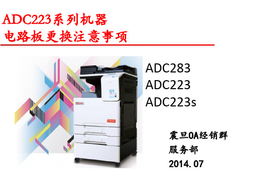
ADC223跟换电路板注意事项
电路板数据备份/恢复结构 (1/6)
本机有2个电路板,在进行故障排除需要注意. 以下是备份/恢复电路板数据的示例.
MFPB
备份总计数器
恢复总计数器
备份设置数据
PRCB
EEPROM 恢复设置数据 维修呼叫:4802并手动 恢复
电路板数据备份/恢复结构 (2/6) 打印控制板(PRCB)
更换步骤
引擎数据备份步骤
• 进入维修模式—进入安全维修模式(停止-0-返回) • 具体操作步骤如下:
停止—0—返回
重启
电路板更换注意事项(1/4)
打印控制板(PRCB)
• 请勿同时将打印控制板(PRCB)和MFP电路板(MFP)更换为全新的打印控制板和MFP电路板.否则 可能会导致备份数据丢失和图像问题. • 通过选择[Service Mode](维修模式) > [Security Service Mode](安全维修模式) > [Engine Data Backup](引擎数据备份) > Save Mode or Reflect Mode(备份或恢复模式) 可以备份或恢复数据. • 更换PRCB后将会显示Service Call: 4802(维修呼叫:4802),此时您需要执行恢复功能. ( 更换PRCB 时,C-4802 属正常操作.) 恢复设置数据
正确更换MFPB步骤: 1、将旧的MFPB上的 EEPROM拔下; 2、将新的MFPB板装到 机器上; 3、将拔下的EEPROM安装 到新的MFPB中; 4、固件升级。
IC芯片(EEPROM)
MFPB
如要用其它机器上拆下的旧板测试,必须将旧MFP电路 板和旧EEPROM板同时一起安装到故障机器上,避免存 储数据丢失
MOC关键设备清单参考

变更管理,全称Manage of change,简称为MOC,又翻译成变化管理,是EHS管理中的基本管理方法和流程之一。
是用于预防伤害发生和保持运营完整性的的过程管理方法。
其技术标准如下:1. 涉及定义Ø变更:可能影响QHSE&S的任何变化(广义定义,来源于EHS管理已经系统化融入运营体系的公司。
其中Q表示质量,第二个S表示安保)。
包括但不仅限于:服务的提供,建筑材料的选择和应用,原料的选择和供应,工艺条件,工艺控制(软硬件),运行程序,人员配备&组织架构,管道、设备的选择和应用以及管道、设备部件的选择和应用。
Ø同类替代:用同样的部分或等效的认可部分代替现存的状况。
同类替换的例子:用一个相同设计规格(相同类型,规格,大小,材料)的热交换器代替另一个热交换器(全部或局部);用一个相同大小,材料,和法兰型号,但不同品牌的阀门代替另一个阀门;根据目前设计参数的范围修改程序的操作变量(例如:当稳定器最大设置温度为华氏200度,那么再提高装置底部的温度从华氏160度到华氏180度);改变检查灭火器的时间从周二到周五。
Ø安全运营限:已知的可接受的运营风险。
这意味着一些方式下QHSE&S的影响由这些限制决定。
确实的安全限应当广泛但并不明显。
安全运营限决定工艺的控制设置、警报和联锁。
2. 变更管理程序的基本要求工厂EHS体系应当包含一个“变更管理程序”。
程序内容最少包含以下:Ø变更的发起:变更的请求可以发起于不同来源。
例如:研发、销售、市场、工厂管理层、技术等。
程序应当表明变更发起的方式。
Ø责任和授权:变更请求应当考虑到原因、设计、回顾和发布或拒绝。
变更管理中责任和授权应当识别并存档。
Ø资源:涉及MOC过程的人员应当具备足够的知识(水平和能力)。
需要的知识和能力应当被确认。
变更应当被一系列具备有关变更影响审核必要能力的人员审核和批准。
2233-气腹机说明书教程

为保护病人,操作人员以及其他接触该设备的人员,工作人员在每一次使用该设备之前,或根据操作手册要求将其 呈报维修之前,都必须对该设备再进行一次消毒处理。
有关技术参数变更的提示! 由于我们的产品在不断地更新,此操作说明手册里所列参数与实际的技术参数和注释会有些许出入。 警告 – 只适用於美国 联邦法律规定,此设备必须由有关的医务人员销售和使用。
5
5.1 5.2 5.2.1 5.2.2 5.2.3 5.2.4 5.2.5 5.2.6 5.3 5.3.1
应用 ............................................................................. 16
功能原理 ............................................................................. 16 操作及操作模式 ....................................................................... 16 供气 .............................................................................. 16 气体消耗 ............................................................................. 16 压力监控 ............................................................................. 16 气流监控 ............................................................................. 17 “一级充气”模式 ..................................................................... 17 “强流”模式 ......................................................................... 17 “警报”按钮 ......................................................................... 18 声音报警脉冲图 ....................................................................... 18
- 1、下载文档前请自行甄别文档内容的完整性,平台不提供额外的编辑、内容补充、找答案等附加服务。
- 2、"仅部分预览"的文档,不可在线预览部分如存在完整性等问题,可反馈申请退款(可完整预览的文档不适用该条件!)。
- 3、如文档侵犯您的权益,请联系客服反馈,我们会尽快为您处理(人工客服工作时间:9:00-18:30)。
mA
pF
Collector–Emitter Saturation Voltage (IC = 500 µA, IF = 1.0 mA) Turn–On Time (IF = 5.0 mA, VCC = 10 V, RL = 100 Ω) Turn–Off Time (IF = 5.0 mA, VCC = 10 V, RL = 100 Ω) Rise Time (IF = 5.0 mA, VCC = 10 V, RL = 100 Ω) Fall Time (IF = 5.0 mA, VCC = 10 V, RL = 100 Ω) Input–Output Isolation Voltage (f = 60 Hz, t = 1.0 sec.)(1,2) Isolation Resistance (VI–O = 500 V)(2) Isolation Capacitance (VI–O = 0, f = 1.0 MHz)(2) 1. 2. 3. 4. 5.
MOCD223
1.4 TA = – 55°C 1.2 1 25°C 100°C 1 10 100 IF, LED FORWARD CURRENT (mA) 1000
1
0.1 0.1
1 10 IF, LED INPUT CURRENT (mA)
100
Figure 1. LED Forward Voltage versus Forward Current
Figure 2. Output Current versus Input Current
14 I C, OUTPUT COLLECTOR CURRENT (mA) 12 10 8 6 4 2 0 0 1 2 3 4 5 6 7 8 9 10 IF = 1 mA MOCD223
I C, OUTPUT COLLECTOR CURRENT (NORMALIZED)
Preferred devices are Motorola recommended choices for future use and best overall value.
REV 2
©MotorolaInc. 1995 Motorola, Optoelectronics Device Data
SCHEMATIC
8 7 6 5
NOTE: Thickness through insulation between input and output is ≥ 0.5 mm.
1. 2. 3. 4. 5. 6. 7. 8.
LED 1 ANODE LED 1 CATHODE LED 2 ANODE LED 2 CATHODE EMITTER 2 COLLECTOR 2 EMITTER 1 COLLECTOR 1
10 NORMALIZED TO: TA = 25°C
1
0.1 –60 –40 –20 0 20 40 60 80 100 120 TA, AMBIENT TEMPERATURE (°C)
1
元器件交易网
MOCD223
MAXIMUM RATINGS — continued (TA = 25°C unless otherwise noted)
Rating TOTAL DEVICE Input–Output Isolation Voltage(1,2) (60 Hz, 1.0 sec. duration) Total Device Power Dissipation @ TA = 25°C Derate above 25°C Ambient Operating Temperature Range(3) Storage Temperature Range(3) Lead Soldering Temperature (1/16″ from case, 10 sec. duration) VISO PD TA Tstg — 3000 250 2.94 –55 to +100 –55 to +150 260 Vac(rms) mW mW/°C °C °C °C Symbol Value Unit
Rating INPUT LED Forward Current — Continuous Forward Current — Peak (PW = 100 µs, 120 pps) Reverse Voltage LED Power Dissipation @ TA = 25°C Derate above 25°C OUTPUT DARLINGTON Collector–Emitter Voltage Collector–Base Voltage Emitter–Collector Voltage Collector Current — Continuous Detector Power Dissipation @ TA = 25°C Derate above 25°C VCEO VCBO VECO IC PD 30 70 7.0 150 150 1.76 V V V mA mW mW/°C IF IF(pk) VR PD 60 1.0 6.0 90 0.8 mA A V mW mW/°C 3 4 Symbol Value Unit 1 2
ELECTRICAL CHARACTERISTICS (TA = 25°C unless otherwise noted)(4)
Characteristic INPUT LED Forward Voltage (IF = 1.0 mA) Reverse Leakage Current (VR = 6.0 V) Capacitance OUTPUT DARLINGTON Collector–Emitter Dark Current (VCE = 5.0 V, TA = 25°C) (VCE = 5.0 V, TA = 100°C) Collector–Emitter Breakdown Voltage (IC = 100 µA) Emitter–Collector Breakdown Voltage (IE = 100 µA) Collector–Emitter Capacitance (f = 1.0 MHz, VCE = 0) COUPLED Output Collector Current (IF = 1.0 mA, VCE = 5.0 V) MOCD223 IC (CTR)(5) VCE(sat) ton toff tr tf VISO RISO CISO 5.0 (500) — — — — — 3000 1011 — 10 (1000) — 3.5 95 1.0 2.0 — — 0.2 — 1.0 — — — — — — — mA (%) V µs µs µs µs Vac(rms) Ω pF ICEO1 ICEO2 V(BR)CEO V(BR)ECO CCE — — 30 7.0 — 1.0 1.0 90 7.8 5.5 50 — — — — nA µA V V pF VF IR C — — — 1.05 0.1 18 1.3 100 — V Symbol Min Typ(4) Max Unit
元器件交易网
MOTOROLA
SEMICONDUCTOR TECHNICAL DATA
Order this document by MOCD223/D
Dual Channel Small Outline Optoisolators
Darlington Output
The MOCD223 device consists of two gallium arsenide infrared emitting diodes optically coupled to two monolithic silicon phototransistor darlington detectors, in a surface mountable, small outline, plastic package. It is ideally suited for high density applications that require low input current and eliminates the need for through–the–board mounting. • Dual Channel Coupler • Convenient Plastic SOIC–8 Surface Mountable Package Style • High Output Current (IC) (500% min) @ 1 mA Input Current • Minimum V(BR)CEO of 30 Volts Guaranteed • Standard SOIC–8 Footprint, with 0.050″ Lead Spacing • Shipped in Tape and Reel, which conforms to EIA Standard RS481A • Compatible with Dual Wave, Vapor Phase and IR Reflow Soldering • High Input–Output Isolation of 3000 Vac (rms) Guaranteed • Meets U.L. Regulatory Requirements, File #E54915 Ordering Information: • To obtain MOCD223 in tape and reel, add R2 suffix to device number as follows: R2 = 2500 units on 13″ reel • To obtain MOCD223 in quantities of 50 (shipped in sleeves) — no suffix Marking Information: • MOCD223 = D223
MOCD223
[CTR = 500% Min] Motorola Preferred Device
