S32K144-EVB SCH
NXP S32K144 32位ARM MCU汽车电子应用方案

NXP S32K144 32位ARM MCU汽车电子应用方案时间:2018-09-13 11:10:32 作者:NXP 来源:中电网NXP公司的S32K144是应用汽车工业的32位ARM ®Cortex®-M0+/M4F MCU高度可升级的KEA 系列产品,工作电压2.7V-5.5V,提供广泛的存储器,外设和封装选择,满足AEC-Q100规范,支持112MHz 频率(HSRUN模式),性能1.25 Dhrystone MIPS per MHz,集成了数字信号处理器(DSP),可配置嵌套中断向量控制器(NVIC)和单精度浮点单元(FPU).本文介绍了S32K144主要特性,系列架构图和评估板S32K144EVB主要特性和电路图.The S32K1xx Product Series further extends the highly sca lable portfolio of ARM ®Cortex ®-M0+/M4F MCUs in theautomotive industry. It builds on the legacy of the KEA series,whilst introducing higher memory options alongside a richerperipheral set extending capability into a variety of automotiveapplications. With a 2.7 –5.5 V supply and focus on automotive environment robustness, the S32K series devicesare well suited to a wide range of applications in electricalharsh environments, and are optimized for cost-sensitive applications offering lowpin-count options. The S32K seriesoffers a broad range of memory, peripherals, and packageoptions. They share common peripherals and pin countsallowing developers to migrate easily within an MCU familyor among the MCU families to take advantage of morememory or feature integration. This scalability allows developers to standardize on the S32K series for their endproduct platforms, maximizing hardware and software reuse,and reducing time-to-market.S32K is a scalable family of AEC-Q100 qua lifi ed 32-bit Arm® Cortex®-M4F and Cortex-M0+ based MCUs targeted for general purpose automotive and high-reliability industrial applications.Scalability – hardware and software compatible families with multiple performance, memory and feature options Integration–ISO CAN FD, CSEc hardware security, ASIL-B ISO26262 functional safety,ultra-low power performance Software Free automotive-grade Software Development Kit (SDK) and S32 Design Studio IDE AUTOSAR and MCAL Support, third-party ecosystem .S32K144主要特性:• Operating characteristics– Voltage range: 2.7 V to 5.5 V– Ambient temperature range: -40℃to 105℃forHSRUN mode, -40℃to 125℃for RUN mode • Arm™ Cortex-M4F/M0+ core, 32-bit CPU– Supports up to 112 MHz frequency (HSRUN mode)with 1.25 Dhrystone MIPS per MHz– Arm Core based on the Armv7 Architecture andThumb?-2 ISA– Integrated Digital Signal Processor (DSP)– Configurable Nested Vectored Interrupt Controller(NVIC)– Single Precision Floating Point Unit (FPU)• Clock interfaces– 4 - 40 MHz fast external oscillator (SOSC)– 48 MHz Fast Internal RC oscillator (FIRC)– 8 MHz Slow Internal RC oscillator (SIRC)– 128 kHz Low Power Oscillator (LPO)– Up to 112 MHz (HSRUN) System Phased LockLoop (SPLL)– Up to 50 MHz DC external square wave input clock– Real Time Counter (RTC)• Power management– Low-power Arm Cortex-M4F/M0+ core withexcellent energy efficiency– Power Management Controller (PMC) with multiplepower modes: HSRUN, RUN, STOP, VLPR, andVLPS. Note: CSEc (Security) or E EPRO M writes/erase will trigger error flags in HSRUN mode (112MHz) because this use case is not allowed toexecute simultaneously. The device will need toswitch to RUN mode (80 Mhz) to execute CSEc(Security) or EEPROM writes/erase.– Clock gating and low power operation supported onspecific peripherals.• Memory and memory interfaces– Up to 2 MB program flash memory with ECC– 64 KB FlexNVM for data flash memory with ECCand EEPROM emulation.Note: CSEc (Security) orEEPROM writes/erase will trigger error flags inHSRUN mode (112 MHz) because this use case isnot allowed to execute simultaneously. The devicewill need to switch to RUN mode (80 MHz) toexecute CSEc (Security) or EEPROM writes/erase. – Up to 256 KB SRAM with ECC– Up to 4 KB of FlexRAM for use as SRAM orEEPROM emulation– Up to 4 KB Code cache to minimize performanceimpact of memory access latencies–QuadSPI with HyperBus™ support• Mixed-signal analog– Up to two 12-bit Analog-to-Digital Converter(ADC) with up to 32 channel analog inputs permodule – One Analog Comparator (CMP) with internal 8-bitDigital to Analog Converter (DAC)• Debug functionality– Serial Wire JTAG Debug Port (SWJ-DP) combines– Debug Watchpoint and Trace (DWT)– Instrumentation Trace Macrocell (ITM)– Test Port Interface Unit (TPIU)– Flash Patch and Breakpoint (FPB) Unit• Human-machine interface (HMI)– Up to 156 GPIO pins with interrupt functionality– Non-Maskable Interrupt (NMI)• Communications interfaces– Up to three Low Power Universal Asynchronous Receiver/Transmitter (LPUART/LIN) modules with DMA supportand low power availability– Up to three Low Power Serial Peripheral Interface (LPSPI) modules with DMA support and low power availability– Up to two Low Power Inter-Integrated Circuit (LPI2C) modules with DMA supportand low power availability– Up to three FlexCAN modules (with optional CAN-FD support)– FlexIO module for emulation of communication protocols and peripherals (UART, I2C, SPI, I2S, LIN, PWM, etc).– Up to one 10/100Mbps Ethernet with IEEE1588 support and two Synchronous Audio Interface (SAI) modules.• Safety and Security– Cryptographic Services Engine (CSEc) implements a comprehensive set of cryptographic functions as described in theSHE (Secure Hardware Extension) Functional Specification. Note: CSEc (Security) or EEPROM writes/erase willtrigger error flags in HSRUN mode (112 MHz) because this use case is not allowed to execute simultaneously. Thedevice will need to switch to RUN mode (80 MHz) to execute CSEc (Security) or EEPROM writes/erase.– 128-bit Unique Identification (ID) number– Error-Correcting Code (ECC) on flash and SRAM memories– System Memory Protection Unit (System MPU)– Cyclic Redundancy Check (CRC) module– Internal watchdog (WDOG)– External Watchdog monitor (EWM) module• Timing and control– Up to eight independent 16-bit FlexTimers (FTM) modules, offering up to 64 standard channels (IC/OC/PWM)– One 16-bit Low Power Timer (LPTMR) with flexible wake up control– Two Programmable Delay Blocks (PDB) with flexible trigger system– One 32-bit Low Power Interrupt Timer (LPIT) with 4 channels– 32-bit Real Time Counter (RTC)• Package– 32-pin QFN, 48-pin LQFP, 64-pin LQFP, 100-pin LQFP, 100-pin MAPBGA, 144-pin LQFP,176-pin LQFP package options• 16 channel DMA with up to 63 request sources using DMAMUX图1.S32K14x系列架构图评估板S32K144EVBThe S32K144EVB is low-cost evaluation platform and development system for quick application prototyping and demonstration for the S32K144 MCU.评估板S32K144EVB主要特性:Small form factorArduin o™ UNO footprint-compatible with expansion “shield” supportOnboard connectivity for CAN, LIN, UART/SCIIntegrating an SBC (UJA1169) and LIN phy (TJA1027)Easy access to the MCU I/O header pins for prototypingPotentiometer, RGB LED, 2x push buttons and 2 touchpadsIntegrated open-standard serial and debug adapter (OpenSDA) with support for several industry-standard debug interfacesFlexible power supply options (micro USB or external 12 V supply)S32K144EVB Evaluation Board图2.评估板S32K144EVB外形图图3.评估板S32K144EVB电路图(1)图4.评估板S32K144EVB电路图(2) 图5.评估板S32K144EVB电路图(3)图6.评估板S32K144EVB电路图(4) 图7.评估板S32K144EVB电路图(5)AO‐Electronics 傲壹电子官网: 中文网:ALPS ADI IR JRC/NJR KEC OTAX Seoul Semiconductor TI Walsin Technology。
华三路由器软件升级指南
木牛 安全库 s32k14x 产品手册说明书

知从木牛SAFETYLIBRARY 恩智浦S32K14X产品手册知从®木牛基础软件平台功能安全库1功能概述S32K14x Safety Library用于帮助客户实现基于S32K14x平台的功能安全要求。
Safety Library具有高扩展性,可以根据不同的客户项目要求进行配置和再开发,最终满足客户的功能安全需求。
S32K14x Safety Library用于实现S32K14x平台的软件安全机制,包括MCU内部模块的测试和硬件安全机制的驱动。
2应用领域S32K14x Safety Library可应用于有功能安全等级需求的控制器。
例如:车身控制器电池管理系统(BMS)网关控制器车载娱乐模块胎压监控系统门控单元车灯控制单元电子驻车制动系统通过将Safety Library集成到基于S32K14x平台的控制器中,可达到ISO26262 ASIL-B的等级要求。
3配置环境4开发背景目前,汽车上的电子电气架构越来越复杂,对汽车电子的安全性要求也越来越高,为了满足汽车的安全性需求,汽车功能安全越来越受到重视。
提到功能安全,大家首先想到的是功能安全的标准ISO26262。
其中,ISO 26262-5(2011) Clause 8中介绍了2个度量:Single-point fault metric(单点故障度量)和Latent-fault metric(潜伏故障度量)。
根据不同的ASIL等级要求,单点故障度量和潜伏故障度量需要达到相应的等级。
对于微控制器(MCU,以下简称MCU),在电子电气系统中,作为SEooC(safety element outof context)进行设计开发。
MCU为了满足以上提到的2个度量要求,需要实现相应的安全机制。
而安全机制可以分配到硬件和软件模块中。
MCU的Safety Library安全库就是实现分配到软件上的安全机制。
5功能描述5.1产品特点可作为复杂驱动集成到AUTOSAR中满足控制器ASIL-B需求可集成到非AUTOSAR软件架构中高扩展性:每个模块实现可配置性,满足不同的客户需求 Safety Library内部程序流监控5.2软件架构5.3配置工具为了满足客户的不同项目需求,提高Safety Library的扩展性,S32K14X Safety Library 实现了各个模块可配置性,并且实现了Safety Library的配置工具。
S32K3X4EVB-Q172 通用汽车应用开发板说明书

Belt-Driven Starter Generator (BSG), Turbo Charger, Fan/Pump ControllerHero SpecsS32K3 FAMILY FEATURESFS26 Safety System Basis Chip[+5 V, +3.3V and +1.5V]MCU Current Monitoring forVDD_HV_A and VDD_HV_B64Mb QSPI Serial NOR FlashMII/RMII Ethernet Interface— SABRE Connector10/100TBase Ethernet— RJ45 ConnectorTJA1043 CAN InterfacesTJA1021 LIN InterfacesMicrocontroller (MCU)32-bit Arm Cortex-M7-based S32K344 (/products/processors-and-microcontrollers/arm-microcontrollers/s32k-automotive-mcus/s32k3-microcoK26 (/products/processors-and-microcontrollers/arm-microcontrollers/general-purpose-mcus/k-series-cortex-m4/k2x-usb/kinetis-k26-180-mhz-Safety System Basis Chip (SBC)FS26 (/products/power-management/pmics-and-sbcs/safety-sbcs/safety-system-basis-chip-sbc-with-low-power-fit-for-asil-d:FS26): Safety syst Transceivers TJA1021 (/products/interfaces/automotive-lin-solutions/lin-2-1-sae-j2602-transceiver:TJA1021): LIN 2.1/SAE J2602 transceiverTJA1043 (/products/interfaces/can-transceivers/can-with-flexible-data-rate/high-speed-can-transceiver-with-standby-and-sleep-mode:TJA1043Hardware Features 64 Mb QSPI NOR flash100 Mbit Ethernet physical LayerPower supply switchMCU voltage/current measurementUser RGB LED2x user push-buttonsADC rotary potentiometer2x touch pad electrodeSoftware Features Free of charge S32 Design Studio IDE (/design/software/development-software/s32-design-studio-ide:S32-DESIGN-STUDIO-IDE) (Eclipse, GFree of charge (/design/automotive-software-and-tools/real-time-drivers-rtd:AUTOMOTIVE-RTD)Real Time Drivers for AUTOSAR and non-AUConfiguration tools for both AUTOSAR and non-AUTOSAR usersFree of charge security firmware: SHE+ compliant NXP supplied, designed for ISO 21434S32 Safety Software Framework (/design/automotive-software-and-tools/s32-safety-software-framework-saf:SAF) (SAF): Six fault detection anFree of charge Safety Peripheral Drivers (SPD)Structural Core Self Test (/docs/en/product-brief/S32K3xx-SCST-PB.pdf) (SCST)Free of charge inter-platform communication framework (/design/automotive-software-and-tools/inter-platform-communication-framework-ipcf:Free of charge Model-Based Design Toolbox (/design/automotive-software-and-tools/model-based-design-toolbox-mbdt:MBDT) for MATLAB :Programing Debug interfaces On-board S32K3 debug interface20-Pin Cortex debug + ETM connectorCompatibility Arduino UNO pint-out compatible with expansion “shield” supportInterfaces On-board HS-CAN2x on-board LINEthernet 100 Mbit Physical Layer with RJ-45 connector for fast prototypingSWD/JTAG debug interface for S32K3 debugger®®BuyS32K3X4EVB-Q172 (/part/S32K3X4EVB-Q172) S32K3X4EVB-Q172 Evaluation and Development Board for General Purpose(/design/automotive-(/design/software/development-(/design/software/development-Design ResourcesGet Started1. Review this Getting Started guide to get familiar with the hardware specifications.Getting StartedGetting Started with the S32K3X4EVB-Q172 Evaluation Board (/document/guide/getting-started-with-the-s32k3x4evb-q172-evaluation-board:GS-S32K3X4EVB-Q172)HTML Oct 6, 2021 GS-S32K3X4EVB-Q1722. Review this user manual to get familiar with the board.User ManualS32K3X4EVB-Q172 Evaluation Board – HW User Manual (/webapp/Download?colCode=S32K3X4EVB-Q172_HW-UM)PDF Rev A Oct 20, 2021 S32K3X4EVB-Q172_HW-UM EnglishDOCUMENTS ( 8 )DESIGN RESOURCES ( 4 )SOFTWARE ( 7 )Reference Manual ( 1 )User Guide ( 1 )Brochure ( 1 )Errata ( 1 )Product Brief ( 4 )Design Tools & Files ( 4 )Embedded Software ( 3 )Development Software ( 4 )DocumentsReference Manual ( 1 )S32K3X4EVB-Q172 Evaluation Board – HW User Manual (/webapp/Download?colCode=S32K3X4EVB-Q172_HW-UM)Hardware User Manual for the S32K3X4EVB-Q172 Evaluation Board.PDF Rev A Oct 20, 2021 S32K3X4EVB-Q172_HW-UM EnglishUser Guide ( 1 )Getting Started with the S32K3X4EVB-Q172 Evaluation Board (/document/guide/getting-started-with-the-s32k3x4evb-q172-evaluation-board:GS-S32K3X4EVB-Q172)This page will help guide you through the process of learning about your S32K3X4EVB-Q172 evaluation boardHTML Oct 6, 2021 GS-S32K3X4EVB-Q172 EnglishBrochure ( 1 )S32K3 Arm Cortex-M7-based Automotive MCUs – Brochure (/docs/en/brochure/S32KBRA4.pdf)The S32K3 family includes scalable 32-bit Arm Cortex-M7 based MCUs in single, dual and Lockstep core configurations supporting up to ASIL D level safety.Features include a hardware security subsystem with NXP firmware, support for firmware over-the-air (FOTA) updates, and ISO 26262 compliant Real-Time Drivers (RTD) software package for AUTOSARTM and non-AUTOSAR.PDF Rev 0 Oct 19, 2021 S32KBRA4 EnglishErrata ( 1 )Mask Set Errata for Mask 0P55A/1P55A - Errata (/webapp/Download?colCode=S32K3X4-0P55A-1P55A-ERRATA)This report applies to mask 0P55A/1P55A for these products S32K344, S32K324 and S32K314PDF Rev 14 Oct 14, 2021 S32K3X4-0P55A-1P55A-ERRATA EnglishProduct Brief ( 4 )S32 Safety Software Framework (SAF) for S32K3xx Microcontrollers - Product Brief (/docs/en/product-brief/S32K3xx-SAF-PB.pdf)The S32 Safety Software Framework (SAF) is a software product containing software components for establishing the safety foundation for customer’s safety applications compliant with ISO 26262 functional safety.PDF Rev 1 Sep 30, 2021 858.4 KB S32K3xx-SAF-PB EnglishStructural Core Self-Test Library (SCST) for S32K3xx Microcontrollers - Product Brief (/docs/en/product-brief/S32K3xx-SCST-PB.pdf)The SCST (Structural Core Self-Test) Library is the software product used for the runtime detection of permanent HW faults in the MCU core.PDF Rev 1 Oct 14, 2021 S32K3xx-SCST-PB EnglishReal-Time Drivers (RTD) for S32K3xx Microcontrollers – Product Brief (/docs/en/product-brief/RTD-S32K3-PB.pdf)S32-based platform products offer Real-Time Drivers (RTD) software supporting both AUTOSAR and non-AUTOSAR (similar to traditional SDKs) applications.PDF Rev 1.5 Nov 11, 2021 397.5 KB RTD-S32K3-PB EnglishInter-Platform Communication Framework (IPCF) - Product Brief (/docs/en/product-brief/IPCFPB.pdf)Inter-Platform Communication Framework (IPCF) is a subsystem which enables applications, running on multiple homogenous or heterogenous processing cores, located on the same chip or different chips, running on different operating systems (AUTOSAR, FreeRTOS etc.), to communicate over various transport interfaces (Shared Memory, etc.).PDF Rev 1 Oct 13, 2021 441.4 KB IPCFPB EnglishDesign ResourcesDesign Tools & Files ( 4 )Printed Circuit Boards and Schematics ( 3 )S32K3X4EVB-Q172 Evaluation Board – REV A Design Files (/webapp/Download?colCode=S32K3X4EVBQ172_CAD_FILES_REVA)Design Files REV A for the S32K3X4EVB-Q172 Evaluation Board.ZIP Rev A Oct 20, 2021 S32K3X4EVBQ172_CAD_FILES_REVAS32K3X4EVB-Q172 Evaluation Board – REV A Schematics (/webapp/Download?colCode=S32K3X4EVB-Q172_SCH)Schematics REV A for the S32K3X4EVB-Q257 Evaluation Board.PDF Rev A Oct 20, 2021 S32K3X4EVB-Q172_SCHDOWNLOAD (/WEBAPP/DOWNLOAD?COLCODE=S32K3X4EVBQ172_CAD_FILES_REVA)DOWNLOAD (/WEBAPP/DOWNLOAD?COLCODE=S32K3X4EVB-Q172_SCH)S32K3 MCUs for General Purpose – REV A Hardware Design Package (/webapp/Download?colCode=S32K3_HW-DesignPackage)Hardware considerations for the S32K3xx MCUs, covering power considerations, bulk/bypass and decoupling required capacitors, reset, crystal, Ethernet and QSPI configurations, and PCB layout recommendations.ZIP Rev A Sep 29, 2021 8.6 MB S32K3_HW-DesignPackageCalculators ( 1 )S32K Power Estimation Tool (PET) (/design/automotive-software-and-tools/s32k-power-estimation-tool-pet:S32K-PET)S32K PET provides a user interface to generate a power profile for an application use case quickly; it also helps calculate a first estimate of the average power consumption for developing automotive battery-operated applicationsDOWNLOAD OPTIONS (/DESIGN/AUTOMOTIVE-SOFTWARE-AND-TOOLS/S32K-POWER-ESTIMATION-TOOL-PET:S32K-PET?TAB=DESIGN_TOOLS_TAB)SoftwareEmbedded Software ( 3 )Embedded Software ( 3 )S32 Safety Software Framework (SAF) (/design/automotive-software-and-tools/s32-safety-software-framework-saf:SAF)The S32 Safety Software Framework (SAF) is a software product containing software components for establishing the safety foundation for customer’s safety applications compliant with ISO 26262 functional safety.DOWNLOAD OPTIONS (/DESIGN/AUTOMOTIVE-SOFTWARE-AND-TOOLS/S32-SAFETY-SOFTWARE-FRAMEWORK-SAF:SAF?TAB=DESIGN_TOOLS_TAB)Automotive Math and Motor Control Library (AMMCLib) (/design/automotive-software-and-tools/automotive-math-and-motor-control-library-ammclib:AMMCLIB)The Automotive Math and Motor Control Library (AMMCLib) set is a collection of production-ready, easy-to-use, software libraries for rapid development of motor control and other real-time embedded systems.DOWNLOAD OPTIONS (/DESIGN/AUTOMOTIVE-SOFTWARE-AND-TOOLS/AUTOMOTIVE-MATH-AND-MOTOR-CONTROL-LIBRARY-AMMCLIB:AMMCLIB?TAB=DESIGN_TOOLS_TAB)Model-Based Design Toolbox (MBDT) (/design/automotive-software-and-tools/model-based-design-toolbox-mbdt:MBDT)The NXP Model-Based Design Toolbox (MBDT) is a comprehensive collection of tools that plug into the MATLAB and Simulink model-based designenvironment to support fast prototyping, verification, and validationDOWNLOAD OPTIONS (/DESIGN/AUTOMOTIVE-SOFTWARE-AND-TOOLS/MODEL-BASED-DESIGN-TOOLBOX-MBDT:MBDT?TAB=DESIGN_TOOLS_TAB)Development Software ( 4 )IDE and Build Tools ( 2 )S32 Design Studio for S32 Platform (/design/software/development-software/s32-design-studio-ide/s32-design-studio-for-s32-platform:S32DS-S32PLATFORM)The S32 Design Studio is a tool suite for developing your applications for NXP Automotive and Ultra-Reliable MicrocontrollersDOWNLOAD OPTIONS (/DESIGN/SOFTWARE/DEVELOPMENT-SOFTWARE/S32-DESIGN-STUDIO-IDE/S32-DESIGN-STUDIO-FOR-S32-PLATFORM:S32DS-S32PLATFORM?TAB=DESIGN_TOOLS_TAB)S32K3 Standard Software (/webapp/swlicensing/sso/downloadSoftware.sp?catid=SW32K3-STDSW-D)S32K3 Standard Software includes Real Time Drivers for AUTOSAR® and non-AUTOSAR operating systems, Standard HSE Security firmware, SafetyPeripheral Drivers, an Inter-Platform Communication Framework (IPCF) for communications between the Cortex-M7 cores. Additionally user also get access to Real Time Driver of FS26 SBC, S32 Design Studio IDE and EB tresos Studio.EXTERNAL Rev 0 Sep 30, 2021 null KB SW32K3-STDSW-DDOWNLOAD (/WEBAPP/SWLICENSING/SSO/DOWNLOADSOFTWARE.SP?CATID=SW32K3-STDSW-D)Test, Debug and Analyzer Software ( 1 )FreeMASTER Run-Time Debugging Tool (/design/software/development-software/freemaster-run-time-debugging-tool:FREEMASTER)Graphical PC host tool to control and debug embedded applications in run-time.DOWNLOAD OPTIONS (/DESIGN/SOFTWARE/DEVELOPMENT-SOFTWARE/FREEMASTER-RUN-TIME-DEBUGGING-TOOL:FREEMASTER?TAB=DESIGN_TOOLS_TAB)Host Device Drivers ( 1 )Inter-Platform Communication Framework (IPCF) (/design/automotive-software-and-tools/inter-platform-communication-framework-ipcf:IPCF)DOWNLOAD (/WEBAPP/DOWNLOAD?COLCODE=S32K3_HW-DESIGNPACKAGE)Get HelpInter-Platform Communication Framework (IPCF) is a subsystem which enables applications, running on multiple homogenous or heterogenous processing cores, located on the same chip or different chips, running on different operating systems (AUTOSAR, FreeRTOS etc.), to communicate over various transport interfaces (Shared Memory, etc.).DOWNLOAD OPTIONS (/DESIGN/AUTOMOTIVE-SOFTWARE-AND-TOOLS/INTER-PLATFORM-COMMUNICATION-FRAMEWORK-IPCF:IPCF?TAB=DESIGN_TOOLS_TAB)RECOMMENDED COMMUNITIESS32K S32 Design Studio MBDT Community Articles FreeMASTERSUGGESTED LINKSFunctional Safety documents AVAILABLE | Require access to the SafeAssure NDA group(//)ABOUT NXP (///COMPANY/OUR-COMPANY/ABOUT-NXP:ABOUT-NXP)CAREERS (///ABOUT/CAREERS-AT-NXP:CAREERS)INVESTORS (///)MEDIA (//)CONTACT (///COMPANY/ABOUT-NXP/CONTACT-US:CONTACTUS)SUBSCRIBE (///SUBSCRIPTION-CENTER)(///NXP)(///company/nxp-semiconductors)(///NXPsemi)Privacy (///about/privacy:PRIVACYPRACTICES)Terms of Use (///about/terms-of-use:TERMSOFUSE)Terms of Sale (///about/our-standard-terms-and-conditions-of-sale-counter-offer:TERMSCONDITIONSSALE)Slavery and Human Trafficking Statement (///company/about-nxp/sustainability/social-responsibility/labor-and-human-rights:LABOR-AND-HUMAN-RIGHTS)Accessibility (///company/our-company/about-nxp/accessibility:ACCESSIBILITY)©2006-2022 NXP Semiconductors. All rights reserved.Search NXP Community SEARCH (HTTPS:///T5/FORUMS/SEARCHPAGE/TAB/MESSAGE?Q=) News Jan 4, 2022 | Read More (https:///news-releases/news-release-details/nxp-advances-iot-connectivity-industrys-first-secure-tri-radio)。
S32K144-EVB_QSG_REV4.0

• Two push-button switches (SW2 and SW3) and two touch electrodes
• Flexible power supply options
• microUSB or • external 12V power supply
• Similar hardware across ARM ®, S12 and Power Architecture® architecture based MCUs
D19
J6-10
D20
J6-08
D21
J6-06
GPIO
J6-04
GPIO
J6-02
PORT PTE3 PTD3 PTD5 PTD12 PTD11 PTD10 PTA17 PTA11
PORT PTE4 PTE5 PTA12 PTA13
PTC16 PTC17 PTD3 PTD1
4 EXTERNAL USE
FUNCTION GPIO GPIO GPIO GPIO GND VDD GPIO GPIO GPIO GPIO
Jumper Settings
Jumper
Configuration
J104
1-2
J107
2-3 (Default) 1-2
2-3 (Default)
5 EXTERNAL USE
J109/J108
Arduino compatible pins
NXP pins
*0ohm resistor is not connected
FUNCTION GPIO GPIO GPIO GPIO GPIO GPIO GPIO GPIO GPIO GPIO
OPV300 OPV310 OPV314系列850nm垂直光吸收激光器(VCSEL)产品说明书
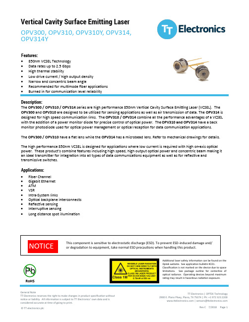
Vertical Cavity Surface Emitting Laser OPV300, OPV310, OPV310Y, OPV314, OPV314YDescription:The OPV300 / OPV310 / OPV314 series are high performance 850nm Vertical Cavity Surface Emitting Laser (VCSEL). The OPV300 and OPV310 are designed to be utilized for sensing applications as well as air transmission of data. The OPV314 is designed for high speed communication links. The OPV310 / OPV314 combine all the performance advantages of a VCSEL with the addition of a power monitor diode for precise control of optical power. The OPV310 and OPV314 have a back monitor photodiode used for optical power management or optical reception for data communication applications.The OPV300 / OPV310 have a flat lens while the OPV314 has a microbead lens. Refer to mechanical drawings for details.The high performance 850nm VCSEL is designed for applications where low current is required with high on -axis optical power. These product ’s combine features including high speed, high output optical power and concentric beam making it an ideal transmitter for integration into all types of data communications equipment as well as for reflective and transmissive switches.Applications:• Fiber Channel • Gigabit Ethernet • ATM • VSR• Intra -System links• Optical backplane interconnects • Reflective sensing • Interruptive sensing•Long distance spot illuminationFeatures:• 850nm VCSEL Technology • Data rates up to 2.5 Gbps • High thermal stability• Low drive current / high output density • Narrow and concentric beam angle• Recommended for multimode fiber applications •Burned in for communication level reliabilityRoHSAdditional laser safety information can be found on the Optek website. See application bulletin #221.Classification is not marked on the device due to space limitations. See package outline for centerline of optical radiance. Operating devices beyond maximum rating may result in hazardous radiation exposure.OPV314YAbsolute Maximum Ratings (T A = 25° C unless otherwise noted)Electrical SpecificationsNotes:(1) Threshold Current is based on the two line intersection method specified in Telcordia GR -468-Core. Line 1 from 4 mA to 6 mA. Line 2 from 0 mA to 0.5 mA.(2) Series Resistance is the slope of the Voltage -Current line from 5 to 8 mA.(3) Slope efficiency is the slope of the best fit LI line from 5 mA to 8 mA using no larger than .25 mAtest interval points.(4) Using data points taken for slope efficiency above, delta L/delta I shall be calculated for eachadjacent pair of points.Additional laser safety information can be found on the Optek website. See application bulletin #221.Classification is not marked on the device due to space limitations. See package outline for centerline of optical radiance. Operating devices beyond maximum rating may result in hazardous radiation exposure.OPV314YElectrical SpecificationsElectrical Characteristics (T A = 25° C unless otherwise noted)(1)Threshold Current is based on the two line intersection method specified in Telcordia GR-468-Core. Line 1 from 4 mA to 6 mA. Line 2from 0 mA to 0.5 mA.(2)Series Resistance is the slope of the Voltage-Current line from 5 to 8 mA.(3)Slope efficiency, is the slope of the best fit LI line from 5 mA to 8 mA using no larger than .25 mA test interval points.(4)Using data points taken for slope efficiency above, delta L/delta I shall be calculated for each adjacent pair of points.(5)ESD Class 1OPV314YNormalized Output Power vs. Forward CurrentN o r m a l i z e d O u t p u t P o w e r (7m A , 25 °C )PerformanceForward Current (mA)OPV314Y1 2 3 VCSEL PDVCSEL PD1 2 VCSEL OPV300 & OPV310PerformanceOPV314Y1) Tolerances are ±0.005 unlessotherwise specified2) Dimensions in inches [mm]OPV3141 2 3 VCSEL PDVCSEL PD。
S32K144+UJA1169(一)连接框架+1169功能说明

S32K144+UJA1169(⼀)连接框架+1169功能说明电路框架如上。
资料如下:UJA1169是⼀款微型⾼速CAN系统基础芯⽚(SBC),包含符合ISO 11898-2:201x(即将合并的ISO 11898-2 / 5/6)的HS-CAN收发器和集成的5 V或3.3 V 250 mA微控制器和/或其他负载的可扩展电源(V1)。
它还具有看门狗和串⾏外围设备接⼝(SPI)。
UJA1169可以在具有总线和本地唤醒功能的低电流待机和睡眠模式下运⾏。
UJA1169有六种变体。
UJA1169TK,UJA1169TK / F,UJA1169TK / X和UJA1169TK / X / F包含5 V稳压器(V1)。
V1是UJA1169TK / 3和UJA1169TK / F / 3中的3.3 V稳压器。
UJA1169TK,UJA1169TK / F,UJA1169TK / F和UJA1169TK / F / 3型号具有第⼆个板载5 V稳压器(V2),该稳压器为内部CAN收发器供电,也可⽤于提供其他板载硬件。
UJA1169TK / X和UJA1169TK / X / F配备了⽤于外接组件的5 V电源(VEXT)。
VEXT对电池,接地和负电压具有短路保护作⽤。
集成的CAN收发器通过V1在内部与微控制器并⾏提供。
UJA1169xx / F变体⽀持符合ISO 11898-6:2013和ISO 11898-2:201x的CAN部分联⽹,并具有包含CAN FD-passive的选择性唤醒功能。
CAN FD被动功能是⼀种允许在睡眠/待机模式下忽略CAN FD总线流量的功能。
CAN FD⽆源部分⽹络⾮常适合同时⽀持CAN FD和经典CAN通信的⽹络。
它允许在CAN FD通信期间不需要通信CAN FD消息的普通CAN控制器保持在部分⽹络睡眠/待机模式,⽽不会产⽣总线错误。
UJA1169实现了当前ISO11898标准(-2:2003,-5:2007,-6:2013)中定义的标准CAN物理层。
恩智浦半导体S32K148 FlexNVM内存使用说明书

应用笔记第 0 版,2017年7月使用S32K148 FlexNVM 内存作者:恩智浦半导体1 介绍本应用笔记介绍了如何使用S32K148器件中 FlexNVM 存储器。
所有S32K1xx 设备都有一个 FlexNVM 分区,但是 FlexNVM 在S32K148器件中具有不同的实现方式。
因此,需要进行具体考虑。
有关 FlexNVM 的更多详细信息,请参阅参考手册。
本应用笔记重点介绍该存储器在 S32K148 中的不同用法,以及每种配置和软件设计需考虑的因素。
该应用笔记会介绍软件设计需要考虑的点、常见处理错误和实际代码示例。
2 概述2.1 词汇表目录1 介绍 (1)2 概述 (1)2.1 词汇表 (1)2.2 FlexNVM描述 (2)3 用例 (3)3.1 未启用 EEPROM 或 CSEc (4)3.2 EEPROM 使能 (5)3.3 使能 EEPROM 和 CSEc (6)4 限制 (6)5 软件建议 (7)6 应用实例 (8)7 参考资料 (9)本节提供了整个文档中使用的术语的简要定义,以帮助读者更好地理解文档。
表1. 词汇表表格在下一页继续......概述表1. 词汇表(续)2.2 FlexNVM描述所有 S32K1xx 系列设备都有一个称为 FlexNVM 的部分。
此部分可用作 Pflash(程序闪存)、Dflash(数据闪存)和模拟EEPROM 备份(E-Flash)。
在大多数系列器件中,此部分的长度为 64KB。
但是,S32K148 设备具有 512KB 长度的FlexNVM加上 1.5MB 的 Pflash,总共 2MB。
我们需要对 FlexNVM 给予特殊考虑。
它可以被读取、编程、擦除、模拟EEPROM 更新或用于 CSEc 加密操作,但一次只能使用其中一个功能。
下面一部分展示了 FlexNVM 的不同用例。
图1. S32K148 内存概览注意512KB FlexNVM 分区与 1.5MB PFlash 不相邻。
S32K144 EVB使用说明

S32K144 EVB使用说明COVER PAGE SUBTITLE PLACEHOLDER目录•S32K144 EVB•使用说明•OPEN SDA介绍•S32DS编译环境•新建S32DS工程•调试工具S32K144 EVBJTAG接口Open SDA 芯片SDA Micro_USB接口重启按键VC125A用户按键SWD接口Micro_USB接口RGB LED灯UART J7J8CANTJA1050 LINTJA1020 MAX662电位器J10MCUPS32K144芯片PS32K144HFT0VLLT 封装LQFP100 规格与Arduino™ 引脚布局兼容可轻松访问MCU I/O芯片上可以连接UART、SCI 和SPI可精确测量电压和模拟的电位计三色LEDUSBDM 调试接口1路LIN接口2路CAN接口电源选项•Micro USB•外部5V电源J71PTA172PTE63PTA164PTE25PTA156PTA117PTA148PTA99PTA1310PTA811PTA1212PTE1513GND 14PTE1615AREF 16PTE11J821PTA2/RX 22PTD323PTA3/TX 24PTD225PTB17/PWM 26PTB1127PTB16/PWM 28PTB1029PTB15/PWM 30PTB931PTB14/PWM 32PT833PTB13/PWM 34PTA135PTB12/PWM36PTA0J961PTD962VIN 63PTC064GND 65PTC166GND 67PTD1068VCC 69PTD12703V371PTD572RST_TGTMCU73PTC274VCC 75PTC376NC J1041PTC1142PTA7/AD 43PTC1044PTA6/AD 45PTC1246PB0/AD 47PTC1348PTB1/AD J7J8J9J10191202362235217561514176625242模块引脚备注RGB三色LED灯R红灯PTB4 G绿灯PTB5 B蓝灯PTE8电位器PTD4(ADC1_SE6 ) KEY PTD15USB_UART USB_UART_TX PTD14(LPUART3_TX) USB_UART_RX PTD13 (LPUART3_RX)OpenSDA_UART OpenSDA_UART_TX PTC7(LPUART1_TX) OpenSDA_UART_RX PTC6(LPUART1_RX)CAN CAN0_TX PTE5(CAN0_TX) CAN0_RX PTE4 (CAN0_RX) CAN1_TX PTC17(CAN2_TX) CAN1_RX PTC16 (CAN2_RX)LIN SBC_LIN_TX PTD7(LPUART2_TX) SBC_LIN_RX PTD6 (LPUART2_RX) LIN_EnPTD11(LPUART2_CTS)JTAG JTAG_TMS PTA4 (JTAG_TMS) JTAG_TCLK PTC4(SWD_CLK) JTAG_TDO PTA10(JTAG_TDO)MCU_3V3CTX0CRX0CTX112V5V LRXLENLTXGNDGND3V3MCU_5VCRX1使用说明1.供电实验板有两种供电方式选择: 使用OPEN SDA或者UART的Micro USB接口供电使用外部供电接口供电•当使用外部供电接口供电时,需要在板子右下角标注有“5V”和“GND”的测试点引出导线连接到电源上。
s32k144和ad7606接口设计与实现
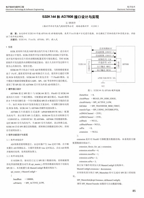
电子技术Electronic Technology电子技术与软件工程Electronic Technology & Software Engineering S32K144和AD7606接□设计与实现文/唐鸿华•(株洲中车时代电气股份有限公司 湖南省株洲市412001 )摘 要:本文针对S32K144外接AD7606的AD 转换电路,采用FlexIO 接口方式进行连接。
本文描述了具体的设计和实现方法,并验 证了设计的正确性。
关键词:S32K144; FlexIO; AD7606; SPI;嵌入式1引言S32K 系列单片机是NXP 推出的汽车电子类单片机,适合高可 靠性设计中使用。
S32K 的软件开发可使用免费的S32DS 开发环境,该开发环境对应芯片的内部模块配置采用可视化模式,同时S32K的软件开发包提供内部模块的底层驱动。
设计人员在开发过程中只需关心具体应用,使用方便。
S32K144单片机由于内部AD 转换精度有限,当转换精度要求 高于1%时,通常采用外接AD 转换芯片方式。
使用串行通信可降低PCB 布线复杂度。
S32K144单片机包含有一个FlexIO 模块,这 个模块可根据需要配置成UART 、SPI 、I2C 等多种串行通信模式。
采用了带SPI 接口的AD7606芯片作为外部AD 转换芯片。
2硬件接口设计AD7606 通 过 SPI 接口与 S32K144 通信。
FlexIO 是 S32K144 系列芯片内的一个通信模块,可配置成SPI 通信模式。
FlexIO 模块的8个外部引脚任意一个均可配置成SPI 的4根通信信号线的任意一个,如在PCB 布局中发现布线交叉复杂时,可调整引脚布局简化PCB 布线。
S32K144与AD7606的硬件连接如图1。
AD7606芯片的通信方式选择(nPAR/SER/BYTE SEL)配置为高电平,表示使用SPI 方式通信。
S32K144发出启动转换信号(CONVSTA 、CONVSTB)到 AD7606, AD7606 开始数据转换,这时BUSY 信号为高电平;当BUSY 信号为低时,表示转换完成。
s32k芯片命名规则
s32k芯片命名规则
S32K芯片的命名规则一般包含以下信息:
1. S32K系列名称:该系列名称表示芯片所属的系列,例如S32K144等。
2. 数字部分:这部分表示芯片的型号和规格,包括芯片的位数、主频、封装等信息。
例如,数字部分为144,表示该芯片为32位MCU,并且主频为48MHz。
3. 后缀部分:该部分通常表示芯片的封装形式和温度范围。
例如,后缀为TQFP,表示该芯片采用TQFP封装;后缀为-40~105℃,表示该芯片的工作温度范围为-40℃~105℃。
综上所述,S32K芯片的命名规则可以帮助用户了解芯片的规格和特点,从而更好地选择和使用该芯片。
恩智浦半导体FlexIO模拟通信和定时外设应用笔记说明书

恩智浦半导体文档编号:AN12174 应用笔记第0版,2018年6月使用 FlexIO 模拟通信和定时外设1. 简介FlexIO 是用在 Kinetis 和 S32K 微控制器系列上的新外设模块。
它具有高度可配置性,能够模拟各种通信协议,例如本文档中提到的UART、I2C、SPI、I2S和LIN,以及其它一些通讯协议,像J1850、I3C、曼彻斯特。
FlexIO 作为微控制器的一个独立外设模块,并不能替代任何通信外设。
FlexIO 的主要特点是可以根据用户的需求来直接构建自己的外设。
本文的示例代码基于 S32K SDK(包含在S32DS_v2018 中的软件开发套件中)和 Bare Metal 的配置代码,以便于更好地了解什么是FlexIO。
通过这些示例,用户可以模拟不同的通信协议和 PWM 信号。
目录1. 简介 (1)2. FlexIO 模块概述 (2)3. 使用FlexIO 模拟UART (4)3.1. 简介 (4)3.2. 配置移位器和定时器 (7)3.3. 函数说明 (10)3.4. 运行例程 (11)4. 使用FlexIO模拟双SPI (12)4.1. 移位器和定时器的配置 (14)4.2. 软件概述 (18)4.3. 操作实现 (20)4.4. 运行例程 (20)5. 使用FlexIO模拟I2C总线主设备 (24)5.1. 简介 (24)5.2. 总体说明 (24)5.3. 移位器和定时器的配置 (25)5.4. 软件概述 (27)5.5. 执行 (30)5.6. 运行例程 (31)6. 使用FlexIO生成PWM (32)6.1. 简介 (32)6.2. 总体概述 (33)6.3. 定时器的配置 (33)6.4. 软件实现概述 (35)6.5. 运行例程 (36)7. 使用FlexIO 模拟I2S 总线Master (36)7.1. 总体概述 (37)7.2. 移位器和定时器的配置 (38)7.3. 软件实现概述 (40)7.4. 运行例程 (40)8. 使用FlexIO模拟 LIN主/从 (41)8.1. 简介 (41)8.2. 使用FlexIO模拟LIN (41)8.3. 配置移位器和定时器 (42)9. 结论 (45)10. 修订历史 (45)FlexIO 模块概述2. FlexIO 模块概述FlexIO 模块具有以下主要硬件资源:∙移位器∙定时器∙引脚可以从 FLEXIO_PARAM 寄存器中获取特定MCU 里面这些资源数量。
MCSPTE1AK144 开发板快速上手指南说明书

MCSPTE1AK144Quick Start GuideS32K144 Development Kit for 3-Phase PMSM and BLDC Motor ControlAUTOMOTIVE MOTOR CONTROL DEVELOPMENT SOLUTIONS2AND BLDC MOTOR CONTROL40 W PM MotorPart Number: 45ZWN24-40Figure 1: S32K144 development kit for 3-phase PMSM and BLDC motor controlDEVKIT-MOTORGD BoardPart Number: DEVKIT-MOTORGDS32K144 Evaluation BoardPart Number: S32K144EVB-Q100GET TO KNOW THE S32K144EVB Figure 2: S32K144 evaluation board OpenSDA USBReset ButtonOpenSDA MCUOpenSDA JTAGSWD ConnectorCAN/LIN Bus External Power Supply (8-18 V)System Basis Chip (SBC)S32K144 MCUTouch ElectrodesRGB LED PotentiometerUser Buttons3Quick Start Guide 4Figure 3: DEVKIT-MOTORGD boardExternal Power Supply(10-18 V)Motor Phase Terminals Shunt Resistor for DC BusCurrent Sensing Jumpers J9/J10/J11 SetEither for PMSM or BLDCMotor Control Application Voltage Regulatorfor Encoder Interface Hall / Encoder InterfaceTerminals for Breaking Resistors3 x Dual FETs3 x Shunt Resistors for 3-Phase Currents Sensing2 x Dual Amplifiers for Bidirectional DC and 3-ph. Stator Current Sensing J8 Voltage Selector for Encoder Interface 5 V/3.3 VGD3000 – FETPre-DriverJ3J15this is the pin configuration for PMSM motor control (see jumper options on page 11).Figure 4: S32K144EVB + DEVKIT-MOTORGD pin assignment6Quick Start GuideFigure 5: S32K144EVB + DEVKIT-MOTORGD pin assignmentmotor control (see jumper options on page 11).7MCSPTE1AK144 FEATURESHardware• S32K144EVB —S32K144 evaluationboard with LIN and CAN connectivitysupport, OpenSDA programming/debugging• DEVKIT -MOTORGD —up to 12 V/5 A3-phase power stage board basedon SMARTMOS GD3000 pre-driverwith condition monitoring and faultdetection• Low-Cost PM Motor —3-phase PMmotor equipped with HALL sensor, 24VDC, 4000 RPM, 40 W, 45ZWN24-40• USB cable• 12 VDC power supplySoftware• Automotive Motor ControlAlgorithms— Field-oriented control (FOC) withfield weakening for sinusoidal motortype (PMSM) — Six-step commutation control for trapezoidal motor type (BLDC)• Evaluation version of the Automotive Math and Motor Control Library Set —Control algorithm built on blocks of precompiled software library • FreeMASTER and MCAT —Application tuning and variables tracking at different levels of the control structure • Design Studio and SDK —Example software created in the S32 Design Studio for Arm ® built on S32 SDK software • SDK - Processor Expert ® —MCU peripherals initialization generated by Processor Expert (PEx)Quick Start GuideDownload installation softwareand documentation at/AutoMCDevKits.2Install S32 Design Studio IDE for Arm®Download and install S32 DesignStudio IDE for Arm available at/S32DS-Arm.3Install FreeMASTERDownload and install FreeMASTERrun-time debugging tool available at /FreeMASTER.4Configure S32K144EVB and DEVKIT-MOTORGD boards Ensure default S32K144EVB and DEVKIT-MOTORGD jumper options (page 11). Place DEVKIT-MOTORGD jumpersJ9, J10, J11 to position 1-2 for PMSM application or 2-3 for BLDC application (page 11).Ensure that motor phase wires are in order: white, blue, green from phase A to phase C. 5Connect thePower SupplyConnect the 12 V power supply to the power supply terminals on DEVKIT-MOTORGD board.Keep the DC supply voltage within the range of 8 to 18 V. The DC power supply voltage affects the maximum motor speed. 6Connect theUSB CableConnect S32K144EVB to the PC using the USB cable. Allow the PC to automatically configure the USB drivers if needed.89STEP-BY-STEP INSTALLATION INSTRUCTIONS CONTINUED7Select Application and MCU ProgramingSelect appropriate PMSM or BLDC motorcontrol application from the installeddirectory NXP\MCSPTE1AK144\sw.Select one of the next two steps (8 or 9)for MCU programming.8Re-program the MCU usingMSD Flash ProgrammerCopy and paste or drag and drop theMotorola S-record *.srec file from theproject folder to the S32K144EVB diskdrive.The software is directly programmedinto the flash memory of the S32K144MCU and executed automatically.9Reprogram the MCU usingS32 Design StudioImport the installed application softwareproject in the S32 Design Studio for Arm ®:• Start S32 DS for Arm application.• Click File–Import.• Select General–Existing Projects into Workspace.• Navigate to the installed application directory: NXP\MC_DevKits\MCSPTE1AK144\sw , choose appropriate project and click OK.• Click Finish.• Click Run – Debug.10FreeMASTER Setup • Start the FreeMASTER application • Open *.pmp FreeMASTER project from the project folder <selected project> FreeMASTER_control by clicking File – Open Project.• Click the green GO! button in the FreeMASTER toolbar or press CTRL+G to enable the communication.• Successful communication is signalized in the status bar at very bottom as“RS232 UART Communication;COMn;speed = 115200”.101Click App Control tab in the MCAT tool menu to display the application control page. When the power supply is connected to theDEVKIT -MOTOGD board, the application is in a READY state indicated by the green LED on S32K144EVB board. RGB LED also indicates:• READY, INIT states lighting green LED• CALIB, ALIGN states flashing green LED• RUN state lighting blue LED • FAULT state lighting red LED2In case of pending faults, click the fault button Clear FAULT on the FreeMASTER MCAT Control Page, or alternatively press and hold SW2 and SW3 buttons on S32K144EVB board simultaneously.3Start the application by pressing the ON/OFF button on theFreeMASTER MCAT control page or by pressing switch SW2/SW3 on S32K144EVB to initiate clockwise/ counter clockwise rotor spinning direction.4Set required speed by changing the Speed Required variable value manually in the variable watch window, by clicking speed gauge , or by pressing the switch SW2/SW3.5To stop the application, click the ON/OFF button on theFreeMASTER MCAT control page or press and hold SW2 and SW3 buttons on S32K144EVB board simultaneously.APPLICATION CONTROL11DEVKIT-MOTORGD JUMPER OPTIONSS32K144EVB JUMPER OPTIONSNXP , the NXP logo and Processor Expert are trademarks of NXP B.V. Arm is a trademark or registered trademark of Arm Limited (or its subsidiaries) in the US and/or elsewhere. The related technology may be protected by any or all of patents, copyrights, designs and trade secrets. All rights reserved. All other product or service names are the property of their respective owners. © 2020 NXP B.V.Document Number: MCSPTE1AK144QSG REV0SUPPORTVisit /support for a list of phone numbers within your region.WARRANTYVisit /warranty for complete warranty information.Get StartedDownload installationsoftware and documentation at /AutoMCDevKits .MCSPTE1AK144。
恩智浦半导体S32K1xx汽车微控制器ADC指南、规格和配置说明书
恩智浦半导体文档编号:AN12217 应用笔记第0版,2018年8月S32K1xx ADC 指南、规格和配置作者:恩智浦半导体1. 简介NXP S32K1xx 汽车微控制器具有 12 位逐次逼近模数转换器(SAR ADC),可用于模拟输入信号的采集和数字化。
本应用笔记提供了有关以下基本主题的信息,便于从ADC模块的使用中获得最大收益:-理解 ADC 常用术语、误差来源和规格。
-提高测量精度的最佳做法。
-S32K1xx 系列的常见触发配置示例。
目录作者:恩智浦半导体 (1)1. 简介 (1)2. ADC 概念、误差源和规格 (2)2.1. ADC 基本概念 (2)2.2. ADC测量中的误差来源 (3)2.3. S32K1xx ADC 规格 (5)3. 提高准确性的最佳措施 (8)4. ADC 触发模式示例 (10)4.1. 软件触发 (11)4.2. PDB 触发器 (11)4.3. 背靠背模式下的 PDB 触发器 (13)4.4. TRGMUX 触发器 (14)5. 参考资料 (16)附录A. 示例代码:ADC 软件触发 (17)附录B. 示例代码:带有 PDB 触发器的 ADC (19)附录 C. 示例代码:带有 PDB 和背靠背触发器的 ADC .. 21S32K1xx ADC 指南、规格和配置,第0版,2018年8月2恩智浦半导体2. ADC 概念、误差源和规格本节解释了用于表征 ADC 的概念和术语以及潜在的误差源,并提供了S32K1xx 系列数据表中的规范参数。
2.1. ADC 基本概念分辨率:ADC 数字输出中代表模拟输入信号的位数。
对于 S32K1xx 系列,分辨率可配置为 8、10 或 12 位。
参考电压:ADC 需要一个参考电压,用于与模拟输入进行逐次近似比较,以产生数字输出。
数字输出是模拟输入相对于该参考电压的比率。
VREF = VREFH – VREFL 其中:VREFH = 高参考电压 VREFL = 低参考电压ADC 输出公式:ADC 的转换公式用于计算特定模拟输入电压对应的数字输出。
恩智浦半导体 S32K1xx EEPROM 功能说明书
AN11983使用 S32K1xx EEPROM 功能第2 版— 2019年5月应用笔记作者:恩智浦半导体1 简介通常有三种方法实现 EEPROM 功能。
其一是使用真正的 EEPROM,例如具有 256 B EEPROM 的 KEA64。
优点是不占用闪存,但缺点是价格昂贵。
第二种方法是使用软件实现 EEPROM 功能,如 KEA8 和 KEA128。
优点是便宜,但缺点是它占用了闪存,包括用于 EEPROM 实现的额外代码和模拟EEPROM 占用的闪存。
第三种方法是使用固件来实现 EEPROM 功能,例如S32K1xx。
优点在于 EEPROM 功能的实现对客户来说是绝对透明的,并且不需要闪存来存储用于 EEPROM 实现的额外代码。
本应用笔记主要介绍 S32K1xx EEPROM (EEE) 功能特性和用法。
S32K1xx EEPROM (EEE) 允许用户将部分片上闪存配置为增强型 EEPROM、额外闪存或两者的组合。
有关本应用笔记中提及的任何参考的详细信息,请参阅 S32K1xx 参考手册和数据手册。
2 S32K1xx EEPROM (EEE) 功能S32K1xx EEPROM (EEE) 具有许多功能,允许更换外部 EEPROMs 以提高其性能。
S32K1xx EEE 功能包括:•自动化–无需客户软件开发。
—重启:EEE 镜像载入 RAM。
—读:直接从 RAM 读取记录。
无 EEE 操作。
—写:直接向 RAM 写入记录。
镜像与 EEE 闪存自动同步。
•利用最佳实践来优化其可靠性和循环耐久性。
—循环负载均衡。
—扇区失效。
•耐掉电。
目录1 简介 (1)2 S32K1xx EEPROM (EEE) 功能 (1)2.1 S32K1xx EEE 工作 (2)2.2 S32K1xx EEE 如何使用内存. . 23 使用 S32K1xx EEE. (4)3.1 S32K1xx EEE 分区 (5)3.2 S32K1xx FlexRAM 配置 (10)3.3 S32K1xx 命令错误处理 (14)3.4 S32K1xx EEE 错误处理 (14)3.5 S32K1xx EEE 启动 (14)3.6 S32K1xx 读取和写入 EEE (15)4 S32K1xx EEE 性能 (16)5 S32K1xx 掉电检测 (16)6 S32K1xx 新的快速写入模式 (17)7 S32K1xx EEPROM 耐久性 (18)8 软件注意事项 (19)8.1 同步操作 (19)8.2 启用 CSEc 和 EEPROM (19)8.3 上电建议 (19)8.4 数据记录检查 (20)8.5 功耗模式转换 (20)9 附录 A EEPROM 示例 (20)10 修订历史 (23)—新的快速写入模式,优先在断电前写入少量数据。
知从科技 知从木牛SBC恩智浦FS6500-FS4500 产品手册
知从木牛SBC恩智浦FS6500-FS4500产品手册知从®木牛基础软件平台功能安全库知从木牛SBC恩智浦FS6500-FS4500产品手册知从®木牛基础软件平台功能安全库1功能概述知从木牛功能安全SBC系列软件旨在打造知从科技自主研发的满足客户功能安全要求的System Basis Chip(SBC)平台化软件产品。
本手册说明了基于恩智浦FS6500-FS4500系列SBC实现的功能安全应用方案、软件架构等内容。
本软件产品可帮助系统工程师和软件工程师能够快速地应用到客户产品中,满足功能安全需求。
本产品实现了的FS6500-FS4500芯片软件驱动功能包含:•多路电源输出管理;•CAN/LIN收发器管理;•LDT定时器管理;•SBC状态机控制、低功耗控制与唤醒管理;•输出电压诊断管理;•MCU与SBC的SPI通信处理;•SBC片内ABIST/LBIST自检管理;•看门狗管理;•MCU错误监控管理;•SBC片外安全关断路径处理。
知从科技已适配开发的FS6500-FS4500系列大部分型号(不限于以下型号):Type Package NoteMC33FS4500CAE 48-pin LQFPexposed pad N/AMC33FS4503CAE 48-pin LQFPexposed pad N/AMC33FS6500CAE 48-pin LQFPexposed pad N/A2应用领域知从木牛功能安全SBC恩智浦FS6500-FS4500驱动软件产品可应用于有各功能安全等级需求的汽车控制器。
例如:电池管理系统(BMS)逆变器(Inverter)DC-DC转换器(DCDC)电动助力转向(EPS)电子驻车系统(EPB)车身控制器(BCM)发动机管理系统(EMS)底盘域线控系统相关应用智能驾驶控制器(ADAS)此SBC恩智浦FS6500-FS4500驱动软件产品手册是为有经验的硬件、软件和功能安全工程师编写的,根据ISO 26262设计,并参考安全相关系统的E-GAS三层架构理论,可以将FS6500-FS4500驱动软件产品集成到客户应用产品的(子)系统中。
S32K144之时钟配置

S32K144之时钟配置⼀般来说,时钟精度、稳定性取决于所采⽤的时钟源,就MCU S32K来说如内部振荡器SIRC,FIRC,128KLPO,外部晶振等,跟所使⽤的外设(FTM, LPIT,LPT,RTC等)和哪⼀路输出时钟(SYS_CLK,BUS_CLK,SPLLDVI1_CLK等)没有直接关系。
由于S32K144提供的时钟源和配置⽅法⽐较多,那么如何有效配置得到⾃⼰想要的时钟呢?下⾯以S32K144为例,从时钟定义图开始,逐步介绍如何寻找S32K144时钟(CORE_CLK, BUS_CLK,)合适的配置⽅法,并根据测试⽅法验证配置是否有效。
0. ⽬标输出⽬标clock clock= 80MHz(以下MHz简称M)bus clock=40MHz, Normal Mode(默认)注意:只有⽀持105℃的部分S32K144型号,core clock才能⽀持到最⾼112M(HSRUN),其他型号不论HSRUN模式,还是RUN模式,最⾼⽀持80M。
测试⼯具PCB: S32K144EVB-Q100IDE: S32DS for ARM 2018.R11.时钟定义配置时钟先从学会看时钟分配图开始,会看图了,配置就成功了⼀半。
因为能实现⽬标的路径可能有多种,这⾥先选中⼀条配置路径,再判断是否可⾏(蓝⾊箭头+框)。
时钟源选择外部晶振8M,即SOSC=8M => SPLL时钟源 SPLL_CLK_SOURCE = SOSC = 8M,2.确认内部时钟要求CORE_CLK/ SYS_CLK 最⾼⽀持112M(HSRUN) , 80M(RUN),⽬标@80M符合要求。
不过,BUS_CLK最⾼⽀持56M(HSRUN), 48M(RUN),⽬标@40M符合要求。
3.确认外部晶振 8M查看S32KEVB-Q100评估板原理图,知外部晶振8M => System PLL输⼊ SPLL_SOURCE=8M4.确认System PLL分频及倍频这⾥选择PREDIV=0, MULT=0b11000 (10进制: 24)VCO_CLK=8M/(0+1) X (24+16) = 320MHzSPLL_CLK=(VCO_CLK)/2 = 160MHz考虑:这⾥MULTI还可以>24 => 倍频因⼦>40,那么能不能配置VCO_CLK >320M,⽽最终CORE_CLK=80M呢?答案是不⾏,因为VCO_CLK最⾼⽀持到320M,可以参考S32K-RM。
NXPS32K144EVB评估板强大而灵活的开发系统

NXPS32K144EVB评估板强大而灵活的开发系统
NXP Semiconductors S32K144EVB 评估板为 NXP S32K144 微控制器(MCU) 提供了强大而灵活的开发系统。
S32K144EVB 包含测试排针、CAN 和 LIN 通信总线、用户按钮、电位器、触摸电极以及预装的 S32K144 MCU。
S32K144EVB 预装有 MSD Flash Programmer OpenSDA 应用程序。
OpenSDA 是一个开放标准的串行和调试适配器。
通过该款GUI 调试实用程序,可轻松方便地将应用程序插入 S32K144 MCU 中。
设计人员还可选择将 S32 Design Studio IDE 与 S32K144EVB 搭配使用。
S32 Design Studio IDE 是用于汽车和超可靠 MCU 的免费集成开发环境,支持对设计进行编辑、编译和调试。
特性
支持 S32K144 100LQFP
小外形尺寸,最大 150mm x 100mm
与 Arduino? UNO 尺寸兼容,支持扩展屏蔽
集成开放标准串行和调试适配器(OpenSDA),可支持多种行业标准调试接口
易于插入 MCU I/O 排针引脚以进行原型设计
片上连接,用于 CAN、LIN 和 UART/SC。
集成式 SBC (UJA1169) 和 LIN phy (TJA1027)
可实现精确的电压和模拟测量的电位器
RGB LED
两个按钮开关(SW2 和 SW3)以及两个触摸电极
灵活的电源选择
MicroUSB
外部 12V 电源。
s32k144例程源码

S32K144例程源码
S32K144是一款高性能的微控制器,广泛应用于各种嵌入式系统。
以下是一个简单的S32K144例程源码,用于演示如何使用该微控制器的PWM功能。
在上面的代码中,我们首先包含了S32K144的头文件,然后定义了主函数。
在主函数中,我们首先初始化了PWM模块,然后在无限循环中设置了PWM周期为1秒,占空比为50%,并启动了PWM波形输出。
接着,我们等待一段时间,
然后停止PWM波形输出。
这个例程可以用来演示如何使用S32K144的PWM功能,并且可以通过修改PWM周期和占空比的值来改变PWM波形的输出。
