3361UA中文资料
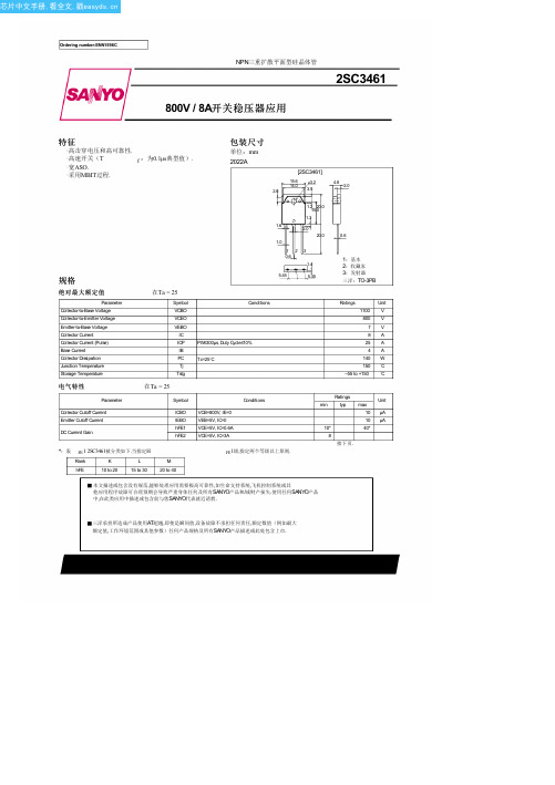
2SC3461中文资料(sanyo)中文数据手册「EasyDatasheet - 矽搜」
Ta=120°C
3
2
25°C
VCE=5V
10
--40°C
DC电7流增益,hFE
5
3 2
23
10 7 5
5 7 0.1 2 3 5 7 1.0 2 3 5 7 10
集电极电流,IC - 一个
ITR05612
VBE(星期六) - IC
IC / IB=5
3 2
基极 - 1发.0射极 Ta=--40°C 饱和电7 压,VBE(星期六) - V 25°C
5
3
2 23
120 °C
5 7 0.1 2 3 5 7 1.0
集电极电流,IC - 一个
2 3 5 7 10 ITR05614
No.1596–2/4
芯片中文手册,看全文,戳
2SC3461
IC -- VBE
9
VCE=5V
8
7
6 5 4
集电极电流,IC - 一个
3 2
2°0C Ta1=
三洋承担所造成产品使用AT超越,即使是瞬间值,设备故障不承担任何责任,额定数值(例如最大 额定值,工作环境范围或其他参数)任何产品规格及所有SANYO产品描述或此处包含上市.
芯片中文手册,看全文,戳
接上页.
Parameter
Gain-Bandwidth Product Output Capacitance Collector-to-Emitter Saturation Voltage Base-to-Emitter Saturation Voltage Collector-to-Base Breakdown Voltage Collector-to-Emitter Breakdown Voltage Emitter-to-Base Breakdown Voltage Collector-to-Emitter Sustain Voltage Turn-ON Time Storage Time Fall Time
2SK3378ENTL-E中文资料(renesas)中文数据手册「EasyDatasheet - 矽搜」

Renesas Electronics product for an application categorized as “Specific” or for which the product is
not intended where you have failed to obtain the prior written consent of Renesas Electronics. The quality grade of each Renesas Electronics product is “Standard” unless otherwise expressly
5. When exporting the products or technology described in this document, you should comply with the applicable export control laws and regulations and follow the procedures required by such laws and regulations. You should not use Renesas Electronics products or the technology described in this document for any purpose relating to military applications or use by the military, including but not limited to the development of weapons of mass destruction. Renesas Electronics products and technology may not be used for or incorporated into any products or systems whose manufacture, use, or sale is prohibited under any applicable domestic or foreign laws or regulations.
美国优倍 安全栅样本及技术手册
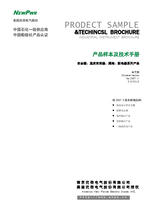
单/双通道电压输入,单/双路输出··········································14
单/双通道开关量输入,开关量输出·········································16
检测端(输入端)安全栅
单/双通道热电偶输入,单/双路输出··········································6
单/双通道热电阻输入,单/双路输出··········································8
单/双通道二、三线制电流输入(配电功能),单/双路输出·································10
安全栅的基本知识···········································首页
安全栅的基本知识·············································1
安全栅通用技术指标············································5
中国国家防爆电气产品质量监督检验中心是中华人民共和国地区监督生产安全防爆产品的权威机构,对本安型安全栅产品有着严格、科学、详细的规定,只有通过该监督站认证的企业及其所开发生产的产品才具备符合标准的安全性能,否则可能会给使用方的设备、人员和生产造成无可估量的损害。
术语解释:
关联设备
一种安装在安全场所,本安电气设备与非本安电气设备之间的相连的电气设备。
输入信号故障输出方式及指示设定·····································34
LM331中文资料_中文手册_芯片中文资料_芯片中文手册
电压-频率变换器LM331LM331是美国NS公司生产的性能价格比较高的集成芯片。
LM331可用作精密的频率电压(F/V)转换器、A/D转换器、线性频率调制解调、长时间积分器以及其他相关的器件。
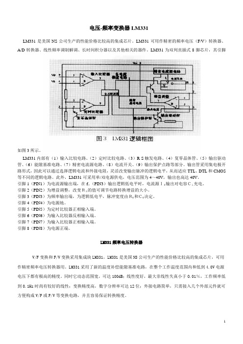
LM331为双列直插式8脚芯片,其引脚如图3所示。
LM331内部有(1)输入比较电路、(2)定时比较电路、(3)R-S触发电路、(4)复零晶体管、(5)输出驱动管、(6)能隙基准电路、(7)精密电流源电路、(8)电流开关、(9)输出保护点路等部分。
输出管采用集电极开路形式,因此可以通过选择逻辑电流和外接电阻,灵活改变输出脉冲的逻辑电平,从而适应TTL、DTL和CMOS 等不同的逻辑电路。
此外,LM331可采用单/双电源供电,电压范围为4~40V,输出也高达40V。
引脚1(PIN1)为电流源输出端,在f0(PIN3)输出逻辑低电平时,电流源IR输出对电容CL充电。
引脚2(PIN2)为增益调整,改变RS的值可调节电路转换增益的大小。
引脚3(PIN3)为频率输出端,为逻辑低电平,脉冲宽度由Rt和Ct决定。
引脚4(PIN4)为电源地。
引脚5(PIN5)为定时比较器正相输入端。
引脚6(PIN6)为输入比较器反相输入端。
引脚7(PIN7)为输入比较器正相输入端。
引脚8(PIN8)为电源正端。
LM331频率电压转换器V/F变换和F/V变换采用集成块LM331,LM331是美国NS公司生产的性能价格比较高的集成芯片,可用作精密频率电压转换器用。
LM331采用了新的温度补偿能隙基准电路,在整个工作温度范围内和低到4.0V电源电压下都有极高的精度。
同时它动态范围宽,可达100dB;线性度好,最大非线性失真小于0.01%,工作频率低到0.1Hz时尚有较好的线性;变换精度高,数字分辨率可达12位;外接电路简单,只需接入几个外部元件就可方便构成V/F或F/V等变换电路,并且容易保证转换精度。
图2是由LM331组成的电压频率变换电路,LM331内部由输入比较器、定时比较器、R-S触发器、输出驱动、复零晶体管、能隙基准电路和电流开关等部分组成。
常用集成电路型号功能对应表
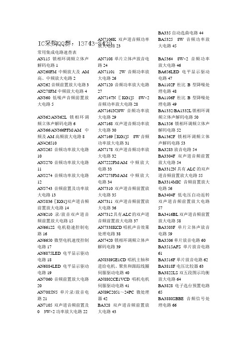
常用集成电路速查表AN115锁相环调频立体声解码电路1AN260FM中频放大及AM 高、中频放大电路2AN262音频前置放大电路3 AN278FM中频放大电路4 AN360低噪声音频前置放大电路5AN362/AN362L锁相环调频立体声解码电路6AN366/AN366PFM/AM中频及AM高频放大电路8 AN426510AN5265音频功率放大电路10AN5270音频功率放大电路11AN5274音频功率放大电路12AN5743音频前置及功率放大电路13AN5836〖KG1]双声道音频前置放大电路14AN6210录/放音双声道音频前置放大电路15AN6612S电机稳速控制电路16AN6650微型电机速度控制电路17AN6875LED电平显示驱动电路18AN6884LED电平显示驱动电路19AN7060音频前置放大电路20AN7085N5单片录/放音电路21AN7105双声道音频前置及03W×2功率放大电路22 AN7106K双声道音频功率放大电路23AN7108单片立体声放音电路24AN711012W音频功率放大电路26AN7120音频功率放大电路27AN7147N〖KG1]58W×2音频功率放大电路28AN7161N20W音频功率放大电路29AN7168双声道音频功率放大电路30AN7169〖KG1]58W音频功率放大电路31AN7178双声道音频功率放大电路32AN7222FM/AM中频放大电路33AN7273FM/AM中频放大电路34AN7310双声道音频前置放大电路35AN7311双声道音频前置放大电路36AN7312具有ALC的双声道音频前置放大电路37AN7338KCD唱机声音效果处理电路38AN7420锁相环调频立体声解码电路39AN8389SE1CD唱机主轴和进给电机、聚焦和跟踪线圈伺服驱动电路40AN8802CE1VCD唱机电机伺服驱动电路41AN89C2051~24PC微处理器42BA328双声道音频前置放大电路43BA335自动选曲电路44BA53258W音频功率放大电路45BA53648W×2音频功率放大电路46BA656LED电平显示驱动电路47BA1102F杜比B型降噪处理电路48BA1106F杜比B型降噪处理电路49BA1332/BA1332L锁相环调频立体声解码电路50BA1356锁相环调频立体声解码电路52BA1362F锁相环调频立体声解码电路53BA3283放音电路54BA3304F双声道音频前置放大电路54BA3312N具有ALC的双声道音频前置放大电路55BA3314MIC音频前置放大电路56BA3404F低电压自动返转双声道音频前置放大电路57BA3416BL双声道音频前置放大电路58BA3503F单片立体声放音电路59BA3506单片放音电路60BA3515AFS单片放音电路61BA3516F单片放音电路62BA3818F电压比较器63BA3822LS双五段图示均衡放大电路64BA3828电子选台预置电路65BA3880SBBE音频信号处理电路66BA4402FM高频放大及变频电路67BA4560/BA4560N双运算放大器67BA5096数字延时混响电路68BA5208AF双声道功率放大电路70BA5402A42W×2音频功率放大电路70BA540645W×2音频功率放大电路71BA6209/BA6209N/BA6209 U/BA6209V电机正/反转驱动电路72BA6227电机稳速电路74BA6296FPCD唱机主轴和进给电机、聚焦和循迹线圈伺服驱动电路75BA6301电机速度伺服控制电路76BA6395FPCD唱机电机伺服驱动电路77BA6796FPCD唱机主轴和进给电机、聚焦和循迹线圈伺服驱动电路79BA7725S音频信号压缩/扩展处理电路80BA7743FSHi-Hi音频磁头信号放大电路81BA7751ALS音频信号处理电路82BA7766SA音频信号处理电路83BA7797F音频信号处理电路85BA15218/BA15218N双运算放大器86BH7770KSHi-Hi音频信号处理电路87 BL3102时钟信号发生器92BL3207电荷耦合延时电路93BU9252FMIC音频信号延时电路94BU9253FS音频信号混响延迟电路95CD3161CS双声道前置放大电路95CD7640CPFM/AM中频放大电路96CD7738单片录/放音电路97CD9608CS双声道音频前置放大电路98CN9832/CS8831语音录/放音电路99CW9300音乐电路102CX20023单片录/放音电路103CX20029AM/FM立体声收音调谐器104CX20107单片录/放音电路105CX20111FM/AM收音机电路106CXA1005P双声道音频功率放大电路107CXA1019/CXA1019M/CXA1019P单片FM/AM收音机电路108CXA1033P单片AM收音机电路113CXA1034/CXA1034P单片立体声放音电路114CXA1081MCD唱机射频放大及伺服电压产生电路116CXA1179AS耳机声音选择控制电路118CXA1191M/CXA1191P单片FM/AM收音机电路120CXA1238M/CXA1238PFM/AM立体声收音机电路122CXA1244SCD唱机电机伺服驱动电路124CXA1262N单片录/放音电路125CXA1278N单片放音电路127CXA1279AS音频信号处理电路128CXA1279BS音频信号处理电路129CXA1622立体声功率放大电路130CXA1642P背景歌声信号消除电路131CXA1644P回声效果发生器132CXA1649M音调处理电路133CXA1735S环绕声信号处理电路134CXA1782BQCD唱机主轴和进给电机、聚焦和寻迹线圈伺服驱动电路136CXA1821MCD唱机射频信号放大电路139CXA8008P单片放音电路140CXD1135QZCD唱机数字信号处理电路141CXD1167QCD唱机数字信号处理电路144CXD1186C-QCD-ROM译码电路147CXD2500AQCD唱机数字信号处理电路150CXD2518QCD唱机EEM解调、RAM控制、纠错CLV伺服驱动电路152CXP1031QCD唱机系统控制电路154D6121G001CD唱机功能键矩阵编码电路155D6121G002CD唱机功能键矩阵编码电路155D6375A数码录音电话数字信号处理电路156D7335PFM高频放大及变频电路159D7640APFM/AM中频放大电路160D7658P具有ALC控制的双声道前置均衡放大电路161 D7666P双路五点LED电平指示电路162D7668AP具有ALC控制的双声道前置放大电路163D7796P五段音调控制电路164DF1700CD唱机数字滤波器165DG41001W音频功率放大电路167DM74LS164M8位移位寄存器168ES3207F视频和音频D/A转换、制式转换、卡拉OK电路169ES56028E数字回声混响电路170ES65033数字混响延时电路171GM71C4263CJ60DROM存储器172GY9403单片数字卡拉OK 电路173H8/3714中央处理器174 HA1137WFM中放、鉴频、AGC及AFC电路175HA1196锁相环调频立体声解码电路176HA137173W音频功率放大电路177HA13777W×2音频功率放大电路178HA139268W×2音频功率放大电路179HA139482W×2音频功率放大电路180HA1406音频前置放大电路181HA11211FM/AM中放及音频功率放大电路182HA11251FM/AM中放、鉴频及音频放大电路183HA12002扬声器保护电路184HA12016立体声解码电路185HA12045/HA12045MP/HA12046/HA12046MP/HA12047/HA12047MP杜比B型降噪处理电路186HA12102双声道音频前置放大电路188HA12413/HA12413AFM/AM中频放大电路189HA13001双声道音频功率放大电路191HA17324高性能四运算放大器192HC138电子控制电路193HT8955A回声效果产生电路194HT-G311音乐电路(电子念佛)195HY403音乐电路195IAP722FM高放、混频电路196IR3N06窄带FM中频放大电路197IR3R20A程序选曲电路198JRC6308BMIC信号放大电路199KA2107直流音量/音调控制电路200KA2206B音频功率放大电路201KA2209低电压双声道音频功率放大电路201KA2213单片磁带录音机电路202KA2261锁相环调频立体声解码电路203KA2263锁相环调频立体声解码电路205KA2284LED电平显示驱动电路206KA2292单片FM/AM立体声收音机电路207KA2402低电压直流电机速度控制电路208KA4558双运算放大器208KA7226具有ALC的双声道均衡放大电路209KA8309BCD唱机伺服信号(SSP)处理电路210KA9201CD唱机射频放大/伺服电压产生电路212KA9201QCD唱机射频放大/伺服电压产生电路213KA22134具有ALC的双前置功率放大电路215KA22136单片放音电路216KA22234双声道五段图示均衡电路217KA22241B具有ALC的双声道均衡放大电路219KA22242具有ALC的双声道前置/均衡放大电路220KA22261双声道前置放大电路221KA22427FM/AM收音机电路222KA22471FM/AM中频放大电路223KD01/KD01C驱动闪光电路224KD07闪烁、音乐电路225KD12D译码、报警电路226KD15音乐电路(十五的月亮)227KD48音乐电路(12首名曲打点报时、光控)227KD151音乐电路(天仙配)228KD152G音乐电路(济公活佛)229KD152H音乐电路(洪湖水,浪打浪)229KD152L音乐电路(兰花草)230KD152M音乐电路(世上只有妈妈好)231KD153音乐电路(叮咚、叮咚)231KD154/KD154B光控音乐电路232KD155音乐电路(雀叫、声控)233KD156音乐电路(鸟叫、余音叮咚)233KD167音乐电路234KD253音乐电路(双音叮咚)234KD253B音乐电路(余音叮咚)235KD254多种合成音乐电路236KD482音乐电路(12首名曲)236KD482FC石英钟定时、音乐打点电路237KD482G音乐电路(7首双音乐曲)237KD482H程控语言(中文)报时电路238KD482Ⅰ音乐电路(16首世界名曲)239KD5603/KD5604音乐电路(欢迎光临/谢谢光临)239 KD5605音乐电路(猫叫)240 KD5608音乐电路(狗叫)241KD5609音乐电路(公鸡叫)241KD56010音乐电路(恭喜发财)242KD56011音乐电路(小鸡叫)242KD56012音乐电路(鸟叫)243KD56013音乐电路(青蛙叫)243KD56014音乐电路(鹅叫)244KD56015音乐电路(蝉叫)244KD56016音乐电路(马叫)245KD56017音乐电路(羊叫)245KD56018音乐电路(蟋蟀叫)246KD56023音乐电路(哈哈笑)246KD9300音乐电路(一首世界名曲)247KD9561B音乐电路(嘀嘟、嘀嘟)247KD9562音乐电路(枪声)248KD9562B音乐电路(光控报警声)249KD9562C音乐电路(单键8音)249KD9563A音乐电路(三声二闪光)250KD9565音乐电路(六声五闪光)251KDA0316LN音频D/A转换电路251KIA6003FM中频放大电路252KIA6040PFM/AM中频放大电路253KIA6043S立体声解码电路254KIA6280H双声道音频功率放大电路255KIA8127F单片FM/AM收音机电路256KM44C1000B语音存储器(ARAM)257KT8554N编/解码电路258LA1130AM中频放大电路259LA1135AM调谐电路260LA1140FM中频放大电路261LA1210AM/FM中放及AM混频电路262LA1231NFM中放、鉴频、AGC及AFC电路263LA1235FM中频放大电路265LA1245AM混频、中放及检波电路266LA1260AM/FM中放及AM混频电路267LA1265AM/FM中放及AM混频电路268LA1816单片收音机电路269LA2000自动选曲电路270LA2785杜比定向逻辑解码电路271LA3160双声道低噪声音频均衡放大电路273LA3161/LA3161A双声道低噪声音频均衡放大电路274LA3210/LA3210B低噪声音频均衡放大电路275LA3220具有ALC的双声道音频均衡放大电路277LA3361锁相环调频立体声解码电路278LA3365锁相环调频立体声解码电路279LA3370锁相环调频立体声解码电路280LA3600五段图示均衡放大电路281LA4100(1.0W)/LA4101(1.5 W)/LA4102(2.1W)音频功率放大电路282LA411227W音频功率放大电路284LA41201W×2音频功率放大电路285LA4125/LA4125T24W×2音频功率放大电路286LA413521W音频功率放大电路287LA416022W音频功率放大电路288LA416205W音频功率放大电路289LA418524W×2音频功率放大电路290LA422035W音频功率放大电路292LA4225音频功率放大电路293LA4261立体声功率放大电路293LA42706W×2音频功率放大电路294LA4275重低音功率放大电路295LA428210W×2音频功率放大电路296LA44406W×2音频功率放大电路297LA4445双声道音频功率放大电路298LA4520立体声耳机功率放大电路299LA4533双声道音频功率放大电路300 LA455021W×2音频功率放大电路301LA4570双声道音频功率放大电路302LA4581MB立体声放音电路303LA4582C音频功率放大电路304LA4585M单片放音电路305LA6324四运算放大器306LA7016电子开关307LAG665D/F单片立体声放音电路309LB1403/LB1403NLED电平显示驱动电路311LB1405LED电平显示驱动电路312LB1409LED电平显示驱动电路313LB3500FM本振频率分频电路314LC5872系统控制微处理器315LC7218锁相环频率合成电路318LC7230数字调谐微处理器318LC7265数字显示(LED)驱动电路321LC7267数字显示(LED)驱动电路323LC75155曲自动选曲电路325LC7538电子音量控制电路326LC7821N双声道8路模拟电子开关电路328LC7872ECD-G译码电路329LC78815M双声道16bitD/A变换电路331LM324/LM324A/LM324N四运算放大器333LR381641CD唱机主轴、字符控制电路335LS0072单片变音电路337LS1240A电话机振铃电路337M5130/M5130P具有ALC的双声道音频前置放大电路338M5201AL音频混合放大电路340M5218AP双运算放大器340M5285FP双声道音频前置放大电路341M38197MA79FCD唱机系统控制与显示驱动电路342M51102/M51102L55W×2音频功率放大电路346M51131L话筒演唱及混响音量控制电路347M51301/M51301P具有ALC的双声道音频前置放大电路348M51515BL/M51515L55W×2音频功率放大电路350M51521AL/M51521L双声道音频前置放大电路351M51543P双声道音频前置放大电路353M51544AL/M51544L双声道音频前置放大电路354M51598FPCD唱机射频预放大电路355M51903LLED显示驱动电路356M52131FPCD唱机伺服电路357M62438FPSRS3D音频处理电路359M65839SP全功能数字卡拉OK电路360M65840变调型卡拉OK电路361M65843AFP数字回声信号处理电路363M65844AP数字回声信号处理电路364M65850P数字混响信号处理电路365MB3110A超低音频信号处理电路366MC4558双运算放大器367 MC14066BPC四组双向模拟开关368MC34012电话机振铃电路369MC34114电话机通话电路369MM5430N数字调谐微处理器371MN1402STN全逻辑电路372MN3101专用时钟驱动电路373MN3102专用时钟驱动电路374MN3108专用时钟驱动电路375MN3207BBD音频延时电路376MN3208BBD音频延时电路376MN662740RECD唱机数字和伺服信号处理、数字滤波及D/A变换电路377MN67730MH数字音频解码电路380 MSP3410DI2C控制多制式音频信号处理电路382MSP4315D-A1I2C控制多制式音频信号处理电路385NE567/SE567音调解码/锁相环电路387NE570降噪处理电路388NE5532AN/NE5532N内部补偿低噪声双运算放大器389NJM2063A/NJM2063AM杜比B型降噪电路390NJM2072MSLSS标准信号检测电路392NJM2177A杜比逻辑定向环绕声解码电路392NJM2234L声道控制开关394NJM4558/NJM4558D/NJM4558DD双运算放大器395NJU4052双4选1模拟开关397NJU9701单片数字延时电路398NJW1103杜比定向逻辑解码电路399PCM1710U音频D/A变换电路401PCM1712L音频D/A变换电路402PCM1716E音频DAC电路404PCM1734UB-E2音频DAC(51)电路405PCM1800数字音频解码电路406PD2395数字音频回响电路407PDG037CD唱机系统控制微处理器409PT2399音频数字延迟混响电路412SAA7283ZP丽音解调解码电路413SAA7345数字信号处理电路415SAA7372数字信号处理和数字伺服电路417SAA9860Hi-Fi多功能音效处理电路419SDV1810音/视频信号处理电路420SECL810音频信号控制电路424SM5840CD唱机数字滤波器425SM5875BM音频D/A变换电路426SN74LS02N2输入端四与非门427STK4191/STK4191Ⅱ50W音频功率放大电路428STK43527W×2音频功率放大电路430STK436210W音频功率放大电路431STK439215W×2音频功率放大电路432T1400接收频率数字显示电路433TA1216AN三声道音频信号处理电路434TA2047NNICAM系统模拟滤波电路436TA2136F/TA2136N声音重演信号(SRS)处理电路437TA7120P/TA7120P-C低噪声音频前置放大电路439TA7130PFM中放及检波电路440TA7137P具有ALC的音频前置放大电路441TA7205/TA7205AP/TA7205P58音频功率放大电路442TA7215P22W×2音频功率放大电路444TA7222AP58W音频功率放大电路445TA7227P55W×2音频功率放大电路446TA7230P24W×2音频功率放大电路447TA7232P22W×2音频功率放大电路448TA7233AP/TA7233P45W ×2音频功率放大电路449 TA7240/TA7240AP/TA7240 P58W×2音频功率放大电路450TA7270/TA7270P58W×2音频功率放大电路452TA7291P加载电机驱动电路453TA7324P噪声抑制电路454 TA7325P双声道音频前置放大电路455TA7335PFM调谐电路456 TA7341P自动选曲电路457 TA7342P锁相环调频立体声解码电路458TA7343/TA7343AP/TA7343 P锁相环调频立体声解码电路459TA7358AP/TA7358PFM前级放大电路460TA7368F11W音频功率放大电路462TA7373F锁相环调频立体声解码电路463TA7376P400mW×2音频功率放大电路464TA7405P双声道音频前置正反向自动翻转电路465 TA7508P四运算放大器466 TA7604AP/TA7604P锁相环调频立体声解码电路467 TA7628AP/TA7628HP/TA7628P音频前置及功率放大电路469TA7630P双声道音量、高音、低音控制电路471TA7640APFM/AM中频放大电路472TA7641/TA7641AP/TA7641BP/TA7641E单片M收音机电路474TA7666PLED电平显示驱动电路476TA7668AP/TA7668BP/TA7668P具有ALC的双声道音频前置放大电路477TA7688F双声道耳机驱动电路479TA7757PFM/AM中频放大电路480TA7766FFM立体声解码电路481TA7770N杜比B型降噪电路483TA7780N轻触机芯驱动电路484TA7784P双声道磁头选择开关、自动翻转及放大电路485TA7792FFM/AM调谐电路486TA7795F单片放音电路487TA7796P多段图示均衡电路488TA8100F单片FM/AM收音机电路489TA8106F立体声耳机激励电路490TA8111AP单片双声道放音电路491TA8115F单片立体声放音电路492TA8119P前置放大和耳机驱动电路494TA8122AFFM/AM收录机电路496TA8126F电子调谐用DC/DC转换电路497TA8127F/TA8127NAM调谐及多路解码电路498TA8132F/TA8132N/TA8132AF/TA8132ANAM/FM中频放大电路501TA8152AFNTV/FM收音机电路504TA8155F单片录/放音电路505TA8158FFM收音机调谐电路506TA8164PFM/AM收音机电路507TA8173AP环绕声信号处理电路508TA8184P环绕声音量控制电路509TA8200AH双声道音频功率放大电路509TA8210AH22W×2双声道音频功率放大电路510TA8211AH双声道音频功率放大电路511TA8213K重低音功率放大电路512TA8218AH音频功率放大电路513TA8256H6W×3音频功率放大电路515TA8628/TA8628N具有电子音量控制的A V/TV开关电路516TA8776N环绕声信号处理电路518TA75393S双电压比较器520TA75458P双运算放大器521TA75558P双运算放大器522TB1204NNICAM解码电路523TB1212N丽音信号处理电路526TB2003-004FN系统控制微处理器528TBA820L/TBA820M/TBA8 20MS2W音频功率放大电路529TBA2800遥控信号接收电路531TC4052B/TC4052BP双4选1模拟开关532TC4053AP三组2路双向模拟开关534TC4066AP/TC4066BP/TC4 066DP四组双向模拟开关536TC74HCT7007AF音频转换电路538TC7SHU04FTL音频转换电路539TC7W32FTE12L51声道音频信号处理电路539TC9121P轻触电子逻辑控制电路540TC9127P锁相环电路542 TC9134P系统控制微处理器543TC9136P数字调谐微处理器545TC9138AP15曲自动选曲电路547TC9146AP数字调谐微处理器549TC9147AP数字调谐微处理器551TC9150P红外遥控解码电路552TC9153P双声道电子音量控制电路553TC9157AP系统控制电路555TC9165P5曲电脑选曲电路557TC9167P9曲电脑选曲电路558TC9289F/TC9289P/TC9289N卡拉OK电路560TC9300F-003数字调谐微处理器561TC9303AN数字调谐微处理器564TC9305-035系统逻辑控制电路565TC9307-010数字调谐微处理器566TC9308AF-029数字调谐微处理器568TC9312N可编程电机控制电路570TC9409BF环绕声信号处理电路571TC9412AFELP话筒音量调整电路573TC9415N数码卡拉OK电路574TC9444F003卡拉OKDSP电路575TD134AF双模前置预分频电路577TD6104PFM预分频电路577TD6301AP荧光显示驱动电路578TDA1013B音频功率放大电路580TDA1083FM/AM收音机电路581TDA1301CD唱机数字伺服电路582TDA1302CD唱机射频放大电路583TDA152020W音频功率放大电路584TDA152112W×2Hi-Fi音频功率放大电路585TDA1521A6W×2Hi-Fi音频功率放大电路586TDA152220W×2音频功率放大电路586TDA1524/TDA1524A立体声音量/音调控制电路587TDA1543数字控制变换电路589TDA1602A单片Hi-Fi录/放音电路590TDA200310W音频功率放大电路591TDA200410W×2音频功率放大电路592TDA200510W×2音频功率放大电路593TDA200612W音频功率放大电路594TDA2007双声道音频功率放大电路595TDA2009/TDA2009A10W×2音频功率放大电路596TDA2320A双声道音频前置放大电路597TDA2611A/TDA2611AQ5W音频功率放大电路598TDA2616/TDA2616Q12W×2具有静音功能的Hi-Fi音频功率放大电路600TDA2820M1W×2音频功率放大电路601TDA2822M14W×2音频功率放大电路602TDA3810混响、立体声和模拟立体声放大电路603TDA7010TFM收音机电路604TDA7021T单片FM收音机电路605TDA7050035W×2音频功率放大电路606TDA7056A超重低音功率放大电路607TDA7057AQ双声道音频功率放大电路608TDA7253音频功率放大电路609TDA7263M双声道音频功率放大电路610TDA7273单片放音电路611 TDA7274电机稳速电路611 TDA7495直流音量控制功率放大电路612TDA7496音频功率放大电路613TDA8420具有I2C总线的Hi-Fi立体声处理电路614TDA8424双声道音频信号处理电路616TDA8425Hi-Fi音频信号处理电路617TDA8732丽音解调电路619 TDA8808CD唱机光电信号处理电路620TDA8809CD唱机径向误差信号处理电路622TDA8822音调控制电路624 TDA9820丽音解码电路624 TDA9859Hi-Fi音频信号处理电路625TDA9860Hi-Fi音频信号处理电路627TEA0665单片杜比C、B型兼容性降噪电路629TEA1014A V/TV切换开关631TEA1330锁相环调频立体声解码电路632TEA202513W×2音频功率放大电路633TEA5581锁相环调频立体声解码电路634TEA5591/TEA5591AFM/A M收音机电路635TEA5711T单片FM/AM收音机电路637 TEA6414TV/A V转换电路638TEA6430音频矩阵切换电路639TPIC326ADB随身听电机控制电路640ULN2204/ULN2204A/ULN2204A-21FM/AM收音机电路641ULN3814A单片AM/FM收音机电路643ULN3839A-1/ULN3839A-2单片AM收音机电路644W27C010-70E2PROM存储器646XR1075BBE音质增强处理电路646XY8901ACD唱机系统控制微处理器647XY8955A数码长延时混响电路649YM3623BCD唱机数字接口电路650μPC1018CFM/AM中频放大电路651μPC1026CFM立体声解码电路653μPC1032H/μPC1032HA双声道音频前置放大电路654μPC1181H358W音频功率放大电路655μPC1185H/μPC1185H2/μPC1185P58W×2音频功率放大电路656μPC1197/μPC1197C锁相环调频立体声解码电路658μPC1212C1W音频功率放大电路660μPC1228H/μPC1228HA双声道音频前置放大电路661μPC1263C/μPC1263C22W×2音频功率放大电路662μPC1313HA双声道音频前置放大电路664μPC1350C045W音频功率放大电路665μPC1470/μPC1470H/μPC1470LM直流电机控制电路666μPC1853音频信号处理及控制电路667μPC1853-01移相矩阵环绕声信号处理电路669μPC1891A矩阵环绕声信号处理电路670μPC1891ACY矩阵环绕声信号处理电路672μPC4558G2/μPC4558G2-E1双运算放大器674μPD1701C-011/μPD1701C-013/μPD1701C-014数字调谐微处理器675μPD1703C-016数字调谐微处理器676μPD1704C-011数字调谐微处理器678μPD1706G-011数字调谐微处理器679μPD1708G571数字调谐微处理器681μPD1719G-014数字调谐微处理器682μPD1723GF-6-94201数字调谐微处理器684μPD7566CS-052CD唱机微处理器685μPD75106-741-3BE系统控制微处理器686μPD75216ACW-183CD唱机微处理器68819A1001W音频功率放大电路69024C01存储器69138CA电机稳速电路6922063A收音/磁带转换电路6922552B微处理器6932606A电机稳速电路695 7358AM/FM波段转换电路6957373AM/FM波段转换电路695。
DMP-3361备自投说明书
DMP-3361备自投装置技术说明书(V2.05)南京磐能电力科技股份有限公司2015年4月目录1概述 (1)1.1适用范围 (1)1.2基本功能 (1)1.3 DMP-3361备自投装置功能一览表 (1)2技术参数 (5)2.1额定参数 (5)2.2装置设备接口 (6)2.3主要技术性能 (6)2.4抗电气干扰能力 (7)2.5绝缘性能 (8)2.6环境条件 (8)3 装置工作原理 (9)3.1备自投原理 (9)3.2备自投过载联切 (30)3.3联跳并网线 (30)3.4分段过流加速保护(带复压闭锁) (30)3.5分段零序加速保护 (32)3.6线路电压异常 (32)3.7母线PT断线告警 (33)3.8 CT断线告警 (33)3.9开关位置监视 (34)4测控功能 (35)4.1遥信功能 (35)5辅助功能 (35)5.1装置自检功能 (35)6装置参数、定值整定及背板端子图 (36)6.1背板端子图 (36)6.2定值清单 (38)7整定说明 (38)7.1备自投开入参数整定 (40)7.2备自投开出参数整定 (41)7.3跳闸矩阵说明 (42)7.4备自投取消合后位置 (43)7.5备自投动作和运行异常出口 (43)7.6电流两相/三相投退功能 (43)8虚端子说明 (44)8.1 SV输入虚端子表 (44)8.2 GOOSE输入虚端子表 (44)8.3 GOOSE输出虚端子表 (46)9使用说明 (47)9.1实时信息功能说明 (47)9.2保护功能说明 (48)9.3远动功能说明 (48)9.4通信功能说明 (48)9.5口令功能说明 (49)9.6装置接地说明 (49)10调试大纲 (49)10.1调试注意事项 (49)10.2装置通电前检查 (49)10.3绝缘检查 (50)10.4上电检查 (50)10.5采样精度检查 (50)10.6开关量输入检查 (50)10.7继电器接点校验 (50)10.8定值校验 (50)10.9跳合闸电流保持试验 (51)11订货须知 (51)12 储存及保修 (51)12.1存储条件 (51)12.2保修 (51)1概述1.1适用范围DMP-3361备用电源自动投入装置,适用于单母线、单母线分段、内桥接线的进线备自投、主变备自投、分段(内桥)备自投,支持电力行业通讯标准DL/T667-1999(IEC60870-5-103)和新一代变电站通讯标准IEC61850。
OPA336UA中文资料
®
OPA4336
OPA336
OPA2336
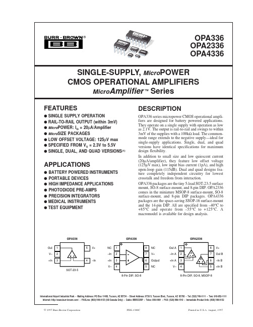
OPA336 OPA2336 OPA4336
SINGLE-SUPPLY, MicroPOWER CMOS OPERATIONAL AMPLIFIERS
MicroAmplifier ™ Series
FEATURES
q SINGLE SUPPLY OPERATION q RAIL-TO-RAIL OUTPUT (within 3mV) q MicroPOWER: IQ = 20µA/Amplifier q MicroSIZE PACKAGES q LOW OFFSET VOLTAGE: 125µV max q SPECIFIED FROM VS = 2.3V to 5.5V q SINGLE, DUAL, AND QUAD VERSIONS(1)
vs Temperature vs Power Supply
TA = –40°C to +85°C Channel Separation, dc
VOS dVOS/dT
PSRR
VS = 2.3V to 5.5V VS = 2.3V to 5.5V
±60
±125
±1.5
25
100
130
0.1
INPUT BIAS CURRENT
OPA336 packages are the tiny 5-lead SOT-23-5 surface mount, SO-8 surface-mount, and 8-pin DIP. OPA2336 comes in the miniature MSOP-8 surface-mount, SO-8 surface-mount, and 8-pin DIP packages. OPA4336 packages are the space-saving SSOP-16 surface-mount and the 14-pin DIP. All are specified from –40°C to +85°C and operate from –55°C to +125°C. A macromodel is available for design analysis.
MC33161DG中文资料

REFERENCE OUTPUT Output Voltage (IO = 0 mA, TA = 25°C)
Load Regulation (IO = 0 mA to 2.0 mA)
Line Regulation (VCC = 4.0 V to 40 V)
Characteristics
Symbol
Min
Typ
Max
Unit
COMPARATOR INPUTS
Threshold Voltage, Vin Increasing (TA = 25°C) (TA = Tmin to Tmax)
Vth
1.245
1.27
1.295
V
1.235
−
1.295
Threshold Voltage Variation (VCC = 2.0 V to 40 V)
+125°C for NCV33161
2
元器件交易网
MC34161, MC33161, NCV33161
ELECTRICAL CHARACTERISTICS (VCC = 5.0 V, for typical values TA = 25°C, for min/max values TA is the operating ambient temperature range that applies [Notes 4 and 5], unless otherwise noted.)
Threshold Hysteresis, Vin Decreasing Threshold Difference |Vth1 − Vth2|
低压电力载波发展方向
低压电力载波通信发展方向深圳市傲立信息技术有限公司吴斌摘要:文中介绍了电力系统低压载波的需求及低压电力配电网的传输特性,通过对比国内外各种电力载波芯片指出低压电力载波发展方向是高性能PLC加上高性能MCU实现载波自动组网及路由。
文中论述了研发基于OFDM技术的PLC的必要性、关键技术及可能困难。
关键词:电力载波自动组网 OFDM1 研究意义目前,电力系统对低压电力载波系统的需求极其旺盛,这种需求来源于电力系统管理的变化。
如今,原先的电力部已经分为3大电网公司,分别是国家电网公司(华北),南方电网公司(华南)、西北电网公司(西北),各个电网公司下面还管辖多个省的电力公司,省电力公司下面管辖着各个市电力局。
从电力部、局到电网公司、电力公司的体制变化,使电力企业的效益最大化成为各电力部门的头等大事。
同时,信息化已经成为这个时代的特点,电力企业生产信息MIS 系统、营业MIS系统,用配电GIS系统、调度自动化系统均是各电力公司每年要重点投入的现代化系统。
电力系统信息化要求电力系统配用电信息基础数据的及时获取,然而,大量的营业MIS所需要的基础数据即电表数据,如今却主要通过人工抄表完成,通过现代化的手段及时进行抄表成为当务之急。
通过电力载波技术进行电力抄表及电力系统电流、电压等生产信息的监测无疑是最便捷的事情,这是因为,电力线路属于电力企业的现有资源。
电力企业需要自动抄表的另一原因是线损管理。
如今,中国电网的电厂与输配电网分开,电力局的最大职能是买电、卖电,即从输电网买电,通过配电网将电卖到千家万户,电力公司的利润主要体现在一买一卖的差价上。
电能在输送、分配过程中存在损失,电力系统称之为线损,线损分中压线损、变损及低压线损,中压线损指的是10KV损失,这个损失发生在二次变电所与10KV/400V用户变压器之间,变损指的是变压器的损耗,低压线损指的是从用户变压器到用户电表之间的损失。
线损计算的前提是各级电表数据的同时准确抄读,然而,目前电力企业主要通过人工进行电表抄收,抄表时间长达半月,通过这样的数据计算的线损误差之大可想而知。
SG6841中文资料

GND
Green Mode Controller
Comp Comp
Slope Compensation 6V 2R R
6 SENSE 2 FB
©System General Corp.
-3-
Version 1.7 (IRO33.0001.B1)
JUL.25,2003
元器件交易网
-1-
Version 1.7 (IRO33.0001.B1)
JUL.25,2003
元器件交易网
High-integrated Green-mode PWM Controller
MARKING DIAGRAMS
8
SG6841T
XXXXXXXYYWWV
DESCRntegrated PWM controllers, SG6841 series, provides several features to enhance the performance of low power flyback converters. To minimize standby power consumption, the proprietary green-mode function provides off-time modulation to linearly decrease the switching frequency under light-load conditions. This green-mode function assists the power supply to easily meet the power conservation requirement. Due to BiCMOS process, the start-up current and operation current is reduced to 30uA and 3mA, respectively, to improve power conversion efficiency. Large start-up resistance can be used for further power saving. Built-in synchronized slope compensation ensures the stability of peak current mode control. A proprietary internal compensation ensures constant output power limit for universal AC input voltage from 90VAC to 264VAC.
MC3371中文资料

7Pin WaveformDescriptionCircuitSymbol 9RAO t200V CCRecovered Audio. This is a composite FM demodulated output having signal and carrier component. The typical level is 1.4 Vpp.RA Out 9100 µAThe filtered recovered audio has thecarrier component removed and is typically 800 mVpp.10Fil InV CC 10Filter In 30 µAFilter Amplifier Input11Fil Out11V CCFilter Out240 µAFilter Amplifier Output. The typical signal level is 400 mVpp.12Sq InSq In1212 µASquelch Input. See discussion in application text.9CC In mod dev RF Pin Symbol Internal EquivalentCircuitDescriptionWaveform5IF InIF In553 k6IF Amplifier Input6DEC1DEC60 µAIF Decoupling. External 0.1 µF capacitors connected to V CC .7IF OutIF Out7120 µAV CC50 µAIF Amplifier Output Signal level is typically 300 mVpp.8Quad InQuad In 850 µAV CC 10Quadrature Detector Input. Signal level is typically 150 mVpp.9RA9200V CCRecovered Audio. This is a composite FM demodulated output having signal and carrier components. Typical level is 800 mVpp.RA OutCIRCUIT DESCRIPTIONThe MC3371 and MC3372 are low power narrowband FM receivers with an operating frequency of up to 60 MHz. Its low voltage design provides low power drain, excellent sensitivity, and good image rejection in narrowband voice and data link applications.This part combines a mixer, an IF (intermediate frequency) limiter with a logarithmic response signal strength indicator, a quadrature detector, an active filter and a squelch trigger circuit. In a typical application, the mixer amplifier converts an RF input signal to a 455 kHz IF signal. Passing through an external bandpass filter, the IF signal is fed into a limiting amplifier and detection circuit where the audio signal is recovered. A conventional quadrature detector is used.The absence of an input signal is indicated by the presence of noise above the desired audio frequencies. This “noise band” is monitored by an active filter and a detector. A squelch switch is used to mute the audio when noise or a tone is present. The input signal level is monitored by a meter drive circuit which detects the amount of IF signal in the limiting amplifier.APPLICATIONS INFORMATION The oscillator is an internally biased Colpitts type with the collector, base, and emitter connections at Pins 4, 1 and 2 respectively. This oscillator can be run under crystal control. For fundamental mode crystals use crystal characterized parallel resonant for 32 pF load. For higher frequencies, use 3rd overtone series mode type crystals. The coil (L2) and resistor RD (R13) are needed to ensure proper and stable operation at the LO frequency (see Figure 13, 45 MHz application circuit).The mixer is doubly balanced to reduce spurious radiation. Conversion gain stated in the AC Electrical Characteristics table is typically 20 dB. This power gain measurement was made under stable conditions using a 50 Ω source at the input and an external load provided by a 455 kHz ceramic filter at the mixer output which is connected to the V CC (Pin 4) and IF input (Pin 5). The filter impedance closely matches the 1.8 kΩ internal load resistance at Pin 3 (mixer output). Since the input impedance at Pin 16 is strongly influenced by a 3.3 kΩ internal biasing resistor and has a low capacitance, the useful gain is actually much higher than shown by the standard power gain measurement. The Smith Chart plot in Figure 17 shows the measured mixer input impedance versus input frequency with the mixer input matched to a 50Ω source impedance at the given frequencies. In order to assure stable operation under matched conditions, it is necessary to provide a shunt resistor to ground. Figures 11, 12 and 13 show the input networks used to derive the mixer input impedance data.Following the mixer, a ceramic bandpass filter is recommended for IF filtering (i.e. 455 kHz types having a bandwidth of ±2.0 kHz to ±15 kHz with an input and output impedance from 1.5 kΩ to 2.0 kΩ). The 6 stage limiting IF amplifier has approximately 92 dB of gain. The MC3371 and MC3372 are different in the limiter and quadrature detector circuits. The MC3371 has a 1.8 kΩ and a 51 kΩ resistor providing internal dc biasing and the output of the limiter is internally connected, both directly and through a 10 pF capacitor to the quadrature detector; whereas, in the MC3372 these components are not provided internally. Thus, in the MC3371, no external components are necessary to match the 455 kHz ceramic filter, while in the MC3372, external 1.8 kΩ and 51 kΩ biasing resistors are needed between Pins 5 and 7, respectively (see Figures 12 and 13).In the MC3371, a parallel LCR quadrature tank circuit is connected externally from Pin 8 to V CC (similar to the MC3361). In the MC3372, a quadrature capacitor is needed externally from Pin 7 to Pin 8 and a parallel LC or a ceramic discriminator with a damping resistor is also needed from Pin 8 to V CC (similar to the MC3357). The above external quadrature circuitry provides 90° phase shift at the IF center frequency and enables recovered audio.The damping resistor determines the peak separation of the detector and is somewhat critical. As the resistor is decreased, the separation and the bandwidth is increased but the recovered audio is decreased. Receiver sensitivity is dependent on the value of this resistor and the bandwidth of the 455 kHz ceramic filter.On the chip the composite recovered audio, consisting of carrier component and modulating signal, is passed through a low pass filter amplifier to reduce the carrier component and then is fed to Pin 9 which has an output impedance of 450 Ω. The signal still requires further filtering to eliminate the carrier component, deemphasis, volume control, and further amplification before driving a loudspeaker. The relative level of the composite recovered audio signal at Pin 9 should be considered for proper interaction with an audio post amplifier and a given load element. The MC13060 is recommended as a low power audio amplifier.The meter output indicates the strength of the IF level and the output current is proportional to the logarithm of the IF input signal amplitude. A maximum source current of 60 µA is available and can be used to drive a meter and to detect a carrier presence. This is referred to as a Received Strength Signal Indicator (RSSI). The output at Pin 13 provides a current source. Thus, a resistor to ground yields a voltage proportional to the input carrier signal level. The value of this resistor is estimated by (V CC(Vdc) – 1.0 V)/60 µA; so for V CC= 4.0 Vdc, the resistor is approximately 50 kΩ and provides a maximum voltage swing of about 3.0 V.A simple inverting op amp has an output at Pin 11 and the inverting input at Pin 10. The noninverting input is connected to 2.5 V. The op amp may be used as a noise triggered squelch or as an active noise filter. The bandpass filter is designed with external impedance elements to discriminate between frequencies. With an external AM detector, the filtered audio signal is checked for a tone signal or for the presence of noise above the normal audio band. This information is applied to Pin 12.。
电力载波芯片BL3361
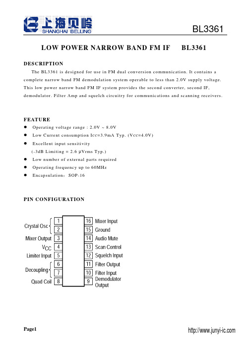
LOW POWER NARROW BAND FM IF BL3361DESCRIPTIONThe BL3361 is designed for use in FM dual conversion communication. It contains a complete narrow band FM demodulation system operable to less than 2.0V supply voltage. This low power narrow band FM IF system provides the second converter, second IF, demodulator. Filter Amp and squelch circuitry for communications and scanning receivers.FEATUREOperating voltage range : 2.0V ~ 8.0VLow Current consumption I C C=3.9mA Typ. (V C C=4.0V)Excellent input sensitivity(-3dB Limiting = 2.6 µVrms Typ.)Low number of external parts requiredOperating frequency up to 60MHzEncapsulation:SOP-16PIN CONFIGURATIONABSOLUTE MAXIMUM RATINGS (Ta=25°C)Characteristic Symbol Value Unit Maximum Supply Voltage Vcc(M AX)10 V Supply Voltage Range Vcc 2.0~8.0 V Detector Input Voltage V I N(DE T) 1.0 Vp-p RF Input Voltage V I N(R F) 1.0 Vrms Mute Function V M UT E-0.5~+5.0 Vpeak Junction Temperature T J150 °C Power Dissipation PD 1.5 W Operating Temperature Topr -30~+70 °C Storage Temperature Tstg -65~150 °CELECTRICAL CHARACTERISTICS(Unless otherwise specified: Ta=25°C, Vcc=4V, fo=10.7MHz, fm=1kHz, ∆f=±3kHz)Characteristics Symbol Test conditions Min Typ Max UnitI C C1Squelch off (V12=2V) 2.9 3.9 4.9mA Squelch CurrentI C C2Squelch on (V12=0V) 4.4 5.4 6.4Audio Output Voltage V OU T Vin=10mVrms 130 160 200 mV r ms Input Limiting Voltage V I N(Li m)-3dB Limiting 2.6 6.0 µVTotal HarmonicTHD V OU T =170mVrms 0.86 % DistortionDetector OutputV NO No Input Signal 1.2 1.5 1.8 V VoltageDrop Voltage AF Gain-3 -0.6 dB Loss ∆Gv Vcc=4V → 2VDetector OutputR OU T450 ΩResistanceFilter Gain Gv Vin=5mVrms, f=10kHz 40 50 dBFilter Output DCV O(D C) 1.0 1.3 1.6 V DC VoltageMute Low Resistance R ON(M u t e)Mute Switch-on 30 50 ΩMute High Resistance R O ff(M u t e)Mute Switch-off 1.0 11 mΩScan Control Low V L(S c a n)Mute off(V12=2V) 0 0.4 V DC Scan Control High V H(S c a n)Mute on(V12=0V) 3.0 3.5 V DC Trigger Hysteresis V TH Squelch on/off 45 100 mV r ms Mixer Conversion Gain G V(M i x)28 dB Mixer Input Resistance R i(M i x) 3.3 kΩMixer Input Capacitance C i(M i x) 2.2 pFBLOCK DIAGRAM AND TEST CIRCUITAPPLICATION CIRCUITTYPICAL PERFORMANCE CHARACTERISTICSOUTLINE DRAWING。
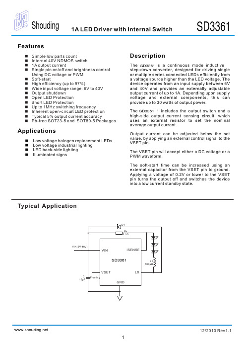
SD3361 输入电压6~40V恒流LED驱动IC,工作模式下的降压转换器
Thermal Information
Parameter Thermal Resistance (Junction to Ambient) Thermal Resistance (Junction to Case) Package SOT23-5 SOT89-5 SOT23-5 SOT89-5 Symbol θjA θjC Maximum 250 160 130 45 °C/W Unit
5
VIN
12/2010 Rev1.1
3
Shouding
1A LED Driver with Internal Switch
SD3361
Absolute Maximum Ratings
These are stress ratings only and functional operation is not implied . Exposure to absolute maximum ratings for prolonged time periods may affect device reliability . All voltages are with respect to ground . Input Voltage Range..........................-0.3V to 40V LX, ISENSE Pin voltage..................... -0.3V to 40V V SET Pin voltage................................ -0.3V to 6V Maximum Junction Temperature..................170 °C Storage Temperature.....................-65 °C to 170 °C Soldering Temperature....................... 300 °C , 5sec
SGA-3363Z;SGA-3363;中文规格书,Datasheet资料

Applications
Gain & Return Loss vs. Frequency
VD= 2.6 V, ID= 35 mA (Typ.)
0 Return Loss (dB) -10
InGaP HBT SiGe BiCMOS Si BiCMOS
15
IRL
10
ORL
-20 -30 -40 0 1 2 3 4 Frequency (GHz) 5 6
/
SGA3363Z
Absolute Maximum Ratings
Parameter
Max Device Current (ID) Max Device Voltage (VD) Max RF Input Power Max Junction Temp (TJ) Operating Temp Range (TL) Max Storage Temp
Rating
70 4 +18 +150 -40 to +85 +150
Unit
mA V dBm °C °C °C
Caution! ESD sensitive device.
Exceeding any one or a combination of the Absolute Maximum Rating conditions may cause permanent damage to the device. Extended application of Absolute Maximum Rating conditions to the device may reduce device reliability. Specified typical performance or functional operation of the device under Absolute Maximum Rating conditions is not implied. The information in this publication is believed to be accurate and reliable. However, no responsibility is assumed by RF Micro Devices, Inc. ("RFMD") for its use, nor for any infringement of patents, or other rights of third parties, resulting from its use. No license is granted by implication or otherwise under any patent or patent rights of RFMD. RFMD reserves the right to change component circuitry, recommended application circuitry and specifications at any time without prior notice. RFMD Green: RoHS compliant per EU Directive 2002/95/EC, halogen free per IEC 61249-2-21, < 1000ppm each of antimony trioxide in polymeric materials and red phosphorus as a flame retardant, and <2% antimony in solder.
ASTM D 3361

D5870Practice for Calculating Property Retention Index of Plastics7E691Practice for Conducting an Interlaboratory Study to Determine the Precision of a Test Method8E1347Test Method for Color and Color Difference Mea-sured by Tristimulus(filter)Colormetry3G23Practice for Operating Light-Exposure Apparatus (Carbon-Arc Type)With and Without Water for Exposure of Nonmetallic Materials9G113Terminology Relating to Natural and Artificial Weathering Tests of Nonmetallic Materials10G141Guide for Addressing Variability in Exposure Testing on Nonmetallic Materials10G147Practice for Conditioning and Handling of Nonme-tallic Materials for Natural and Artificial Weathering Tests10G151Practice for Exposing Nonmetallic Materials in Ac-celerated Test Devices That Use Laboratory Light Sources10G169Guide for Appliction of Basic Statistical Methods to Weathering Tests103.Terminology3.1The definitions given in Terminology G113are appli-cable to this practice.4.Significance and Use4.1The ability of a paint or coating to resist deterioration of its physical and optical properties caused by exposure to light, heat,and water can be very significant for many applications. This practice is intended to induce property changes associated with end-use conditions,including the effects of sunlight, moisture,and heat.The exposure used in this practice is not intended to simulate the deterioration caused by localized weather phenomena such as atmospheric pollution,biological attack,and saltwater exposure.4.2Cautions—Variation in results may be expected when different operating conditions are used.Therefore,no reference to the use of this practice shall be made unless accompanied by a report prepared according to Section10that describes the specific operating conditions used.Refer to Practice G151for detailed information on the caveats applicable to use of results obtained according to this practice.N OTE2—Additional information on sources of variability and on strategies for addressing variability in the design,execution,and data analysis of laboratory accelerated exposure tests is found in Guide G141.4.2.1The spectral power distribution of light from an unfiltered open-flame carbon arc is significantly different from that produced in light and water exposure devices using other carbon-arc configurations or other light sources.The type and rate of degradation and the performance rankings produced by exposures to unfiltered open-flame carbon-arcs can be much different from that produced by exposures to other types of laboratory light sources.Typically,exposures conducted ac-cording to this practice will produce degradation faster than similar exposures conducted according to Practice D822or D5031and may cause different types of degradation.4.2.2Interlaboratory comparisons are valid only when all laboratories use the same type of carbon-arc and exposure conditions.4.3Reproducibility of test results between laboratories has been shown to be good when the stability of materials is evaluated in terms of performance ranking compared to other materials or to a control.11,12Therefore,exposure of a similar material of known performance(a control)at the same time as the test materials is strongly recommended.It is recommended that at least three replicates of each material be exposed to allow for statistical evaluation of results.4.4Test results will depend upon the care that is taken to operate the equipment.Significant factors include regulation of line voltage,freedom from salt or other deposits from water, temperature and humidity control,and conditions of the electrodes.4.5All references to exposures in accordance with this practice must include a complete description of the test cycle used.5.Apparatus5.1Usefiltered open-flame carbon-arc apparatus with auto-matic humidity control that conforms to the requirements defined in Practice G151.5.2Do not place anyfilters between the openflame carbon arc and the test specimens.6.Hazards6.1Warning—In addition to other precautions,never look directly at the carbon arc because UV radiation can damage the eye.Most carbon-arc machines are equipped with door safety switches,but users of old equipment must be certain to turn off the power to the carbon arc before opening the test-chamber door.6.2This light source generates ozone and nitrous oxides. Vent exhaust from the exposure device to the atmosphere. 6.3The burning carbon rods used in these devices become very hot during use.Make sure to allow at least15min for the arcs to cool after the device is turned off before attempting to change the carbon rods.6.4Carbon residue and ash are known respiratory irritants. Wear an appropriate high-efficiency dust respirator,gloves,and safety glasses when handling or changing carbon rods.Make sure to wash any carbon residue from hands or arms prior to eating or drinking.7.Test Specimens7.1Apply the coating toflat(plane)panels with the sub-strate,method of preparation,method of application,coating7Annual Book of ASTM Standards,V ol08.03.8Annual Book of ASTM Standards,V ol14.02.9Discontinued2000;see1999Annual Book of ASTM Standards,V ol14.04. 10Annual Book of ASTM Standards,V ol14.04.11Fischer,R.,“Results of Round Robin Studies of Light-and Water-Exposure Standard Practices,”Accelerated and Outdoor Durability Testing of Organic Materials,ASTM STP1202,ASTM,1993.12Ketola,W.,and Fischer,R.,“Characterization and Use of Reference Materials in Accelerated Durability Tests,”VAMAS Technical Report No.30,NIST,June1997.system,film thickness,and method of drying consistent with the anticipated end use,or as mutually agreed upon between the producer and user.7.2Panel specifications and methods of preparation include but are not limited to Practices D609or D1730,or Specifi-cation D358.Select panel sizes suitable for use with the exposure apparatus.7.3Coat test panels in accordance with Test Methods D823, then measure thefilm thickness in accordance with an appro-priate procedure selected from Test Methods D1005,D1186, or D1400.Nondestructive methods are preferred because panels so measured need not be repaired.7.4Prior to exposing coated panels in the apparatus,condi-tion them at2362°C(7363°F)and5065%relative humidity for one of the following periods in accordance with the type of coating:Baked coatings24hRadiation-cured coatings24hAll other coatings7days min7.4.1Other procedures for preparation of test specimens may be used if agreed upon by all interested parties.7.5Mount specimens in holders so that only the minimum specimen area required for support by the holder is covered. Do not use this covered area of the specimen as part of the test area.7.6Unless otherwise specified,expose at least three repli-cate specimens of each test and control material.7.7Follow the procedures described in Practice G147for identification and conditioning and handling of specimens of test,control,and reference materials prior to,during,and after exposure.7.8Do not mask the face of a specimen for the purpose of showing on one panel the effects of various exposure times. Misleading results may be obtained by this method,since the masked portion of the specimen is still exposed to temperature and humidity cycles that in many cases will affect results. 7.9Retain a supply of unexposedfile specimens of all materials evaluated.7.9.1When destructive tests are run,it is recommended thata sufficient number offile specimens be retained so that the property of interest can be determined on unexposedfile specimens each time exposed materials are evaluated.N OTE3—Since the stability of thefile specimen may also be time-dependent,users are cautioned that over prolonged exposure periods,or where small differences in the order of acceptable limits are anticipated, comparison of exposed specimens with thefile specimen may not be valid. Nondestructive instrumental measurements are recommended whenever possible.7.10Specimens should not ordinarily be removed from the exposure apparatus for more than24h,then returned for additional tests,since this does not produce the same results on all materials as tests run without this type of interruption.When specimens are removed from the exposure apparatus for24h or more,then returned for additional exposure,report the elapsed time as noted under Section10.8.Procedure8.1Unless otherwise specified,use the following exposure cycle:8.1.1Sixty min light only with black panel temperature controlled at6365°C(14569°F)and relative humidity controlled at5065%.N OTE4—The black panel temperature is for equilibrium conditions. There will be a period immediately after the dark cycle where the black panel temperature will be less than the control limits given.8.1.2Sixty min dark with water spray on the back of test specimens.During this dark cycle the chamber air temperature shall be controlled at3263°C(9065°F)and the relative humidity shall be controlled at9565%.8.1.3Adjust the water spray so that the only water on the face of the test specimens is from the dew formation caused by the chilled water sprayed on the back of the specimens.The temperature of the water sprayed on the back of the specimens shall be controlled at7.262°C(4564°F).N OTE5—Each set point and its tolerances given in this section represent an operational control point for equilibrium conditions at a single location in the cabinet,which may not necessarily represent the uniformity of those conditions throughout the cabinet.ASTM Committee G03is working to refine these tolerances and address the uniformity issue.8.2Practice D822lists other exposure cycles that may be used.8.3Place test specimens in the device according to the manufacturer’s recommendations.It is recommended that all unused spaces in the specimen exposure area befilled with blank metal panels.8.4If the irradiance uniformity within the exposure area does not meet the requirements of Practice G151for exposure without repositioning,use one of the procedures described in Practice G151to ensure that specimens receive as uniform a radiant exposure as possible.8.4.1If specimen repositioning is used,and no repositioning schedule is specified,use the following procedure for specimen repositioning:8.4.1.1Once per week,move all holders in the top half of the specimen exposure area to the bottom half and move all holders in the bottom half of the exposure area to the top half. Do not reposition the specimens within the holder.N OTE6—Incident energy at the top and bottom of the specimen rack is often only70%of that at the center.This condition requires that the procedures described in8.4be followed to ensure uniformity of radiant exposure.8.5Water Purity:8.5.1The purity of water used is very important.Without proper treatment to remove cations,anions,organics,and particularly silica,exposed panels will develop spots or stains that may not occur in exterior exposures.8.5.2Follow the requirements for water purity described in Practice G151.8.5.3If specimens are found to have deposits or stains after exposure in the apparatus,the water purity must be checked to determine if it meets the requirements of8.5.2.On some occasions,exposed specimens can be contaminated by deposits from bacteria that can grow in the purified water used for specimen spray.If bacterial contamination is detected,the entire system used for specimen water spray must beflushed with chlorine and thoroughly rinsed prior to resuming expo-sures.8.5.4When the water purity requirements are met and there is disagreement between parties on the extent of problems caused by stain or deposit,run referee tests in at least one other laboratory that can meet the water quality requirements de-scribed in8.5.8.5.5For devices with humidity control,it is recommended that deionized water be used when generating water vapor to control humidity.8.6Some tests for lightfastness are run without any speci-men wetting.When this type of test is required,omit the period where water is sprayed on specimens.8.7Identification of any control specimen used shall accom-pany the report.9.Periods of Exposure and Evaluation of Test Results 9.1In most cases,periodic evaluation of test and control materials is necessary to determine the variation in magnitude and direction of property change as a function of exposure time or radiant exposure.9.2The time or radiant exposure necessary to produce a defined change in a material property can be used to evaluate or rank the stability of materials.This method is preferred over evaluating materials after an arbitrary exposure time or radiant exposure.9.2.1Exposure to an arbitrary time or radiant exposure may be used for the purpose of a specific test if agreed upon between the parties concerned or if required for conformance to a particular specification.When a single exposure period is used,select a time or radiant exposure that will produce the largest performance differences between the test materials or between the test material and the control material.9.2.2The minimum exposure time used shall be that nec-essary to produce a substantial change in the property of interest for the least stable material being evaluated.An exposure time that produces a significant change in one type of material cannot be assumed to be applicable to other types of materials.9.2.3The relation between time to failure in an exposure conducted according to this practice and service life in an outdoor environment requires determination of a valid accel-eration factor.Do not use arbitrary acceleration factors relating time in an exposure conducted according to this practice and time in an outdoor environment because they can give errone-ous information.The acceleration factor is material dependent and is only valid if it is based on data from a sufficient number of separate exterior and laboratory accelerated exposures so that results used to relate times to failure in each exposure can be analyzed using statistical methods.N OTE7—An example of a statistical analysis using multiple laboratory and exterior exposures to calculate an acceleration factor is described by J.A.Simms.13See Practice G151for more information and additional cautions about the use of acceleration factors.9.3After each exposure increment,determine the changes in exposed specimens.Test Methods D523,D610,D659, D660,D662,D714,D772,D2244,D2616,D4214, E1347,or Practice D1729may be used.Consider product use requirements when selecting appropriate methods.9.3.1Other methods for evaluating test specimens may be used if agreed upon between all interested parties.N OTE8—For some materials,changes may continue after the specimen has been removed from the exposure apparatus.Measurements(visual or instrumental)should be made within a standardized time period or as agreed upon between interested parties.The standardized time period needs to consider conditioning prior to testing.9.4It is recommended that the following procedure be followed when results from exposures conducted according to this practice are used in specifications.9.4.1If a standard or specification for general use requiresa defined property level after a specific time or radiant exposure in an exposure test conducted according to this practice,base the specified property level on results from round-robin experiments run to determine the test reproduc-ibility for the exposure and property measurement procedures. Conduct these round robins according to Practice E691or D3980and include a statistically representative sample of all laboratories or organizations that would normally conduct the exposure and property measurement.9.4.2If a standard or specification for use between two or three parties requires a defined property level after a specific time or radiant exposure in an exposure test conducted accord-ing to this practice,base the specified property level on at least two independent experiments run in each laboratory to deter-mine the reproducibility for the exposure and property mea-surement process.The reproducibility of the exposure/property measurement process is then used to determine the maximum or minimum level of property after the exposure that is mutually agreeable to all parties.9.4.3When reproducibility in results from an exposure test conducted according to this practice has not been established through round-robin testing,specify performance requirements for materials in terms of comparison(ranked)to a control material.All specimens shall be exposed simultaneously in the same device.All concerned parties must agree on the specific control material used.9.4.3.1Conduct analysis of variance to determine whether the differences between test materials and any control materials used are statistically significant.Expose replicates of the test specimen and the control specimen so that statistically signifi-cant performance differences can be determined.N OTE9—Fischer illustrates use of rank comparison between test and control materials in specifications.14N OTE10—Guide G169includes examples showing use of analysis of variance to compare materials.10.Report10.1Report the following information:10.1.1Type and model of exposure device.10.1.2Type of light source.10.1.3Average distance from specimens to light source. 10.1.4Type of black panel(uninsulated or insulated)used.13Simms,J.A.,Journal of Coatings Technology,V ol50,1987,pp.45-53.14Fischer,R.,Ketola,W.,“Impact of Research on Development of ASTM Durability Testing Standards,”Durability Testing of Non-Metallic Materials,ASTM STP1294,ASTM,1995.10.1.5If required,irradiance in W/(m 2·nm),or radiantexposure in J/m 2,at the sample location,and the wavelengthregion in which the measurements were made.10.1.5.1Do not report irradiance or radiant exposure unlessdirect measurement of spectral irradiance was made during theexposure.10.1.6Elapsed exposure time.10.1.7Light and dark-water-humidity cycle employed.10.1.8Operating black panel temperature.10.1.9Operating relative humidity.10.1.10Type of spray water,if water spray was used.10.1.10.1Total solids and silica level of water used forspecimen spray (if above limits specified in 8.5).10.1.11Type of spray nozzle.10.1.12Specimen repositioning procedure.10.1.13Results of property tests.Where retention of char-acteristic property is reported,calculate results according toPractice D 5870.N OTE 11—In some cases,exposures are conducted by a contracting agency but property tests are conducted by the contracting party.In these cases,the agency that conducts the exposures cannot report results from property tests.11.Precision and Bias 11.1Precision —The repeatability and reproducibility of results obtained in exposures conducted according to this practice will vary with the materials being tested,the material property being measured,and the specific test conditions and cycles that are used.11.2Bias —Bias can not be determined because no accept-able standard weathering reference materials are available.12.Keywords 12.1carbon arc;degradation;dew cycle;exposure;light exposure;ultraviolet;weatheringThe American Society for Testing and Materials takes no position respecting the validity of any patent rights asserted in connection with any item mentioned in this ers of this standard are expressly advised that determination of the validity of any such patent rights,and the risk of infringement of such rights,are entirely their own responsibility.This standard is subject to revision at any time by the responsible technical committee and must be reviewed every five years and if not revised,either reapproved or withdrawn.Your comments are invited either for revision of this standard or for additional standards and should be addressed to ASTM Headquarters.Your comments will receive careful consideration at a meeting of the responsible technical committee,which you may attend.If you feel that your comments have not received a fair hearing you should make your views known to the ASTM Committee on Standards,at the address shown below.This standard is copyrighted by ASTM,100Barr Harbor Drive,PO Box C700,West Conshohocken,PA 19428-2959,United States.Individual reprints (single or multiple copies)of this standard may be obtained by contacting ASTM at the above address or at 610-832-9585(phone),610-832-9555(fax),or service@ (e-mail);or through the ASTM website().。
DF3361EA电动机保护测控装置技术说明书
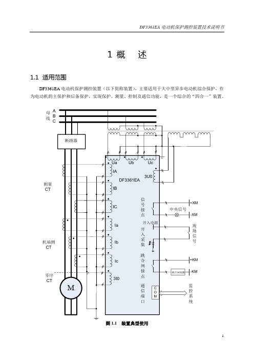
2.1
a)直流工作电压:220V或110V(标称范围±20%,直流中交流分量不大于直流额定值的5%)
b)交流输入电压:100/ V或100V,频率50Hz(标称范围±2.5Hz)
c)交流输入电流:5A或1A,频率50Hz(标称范围±2.5Hz)
2.2
a)交流电流:0.05In~20In(In为额定值,以下相同)
能承受IEC1000-4-2标准Ⅳ级,试验电压接触放电8kV,空气放电15kV。
c)辐射电磁场干扰试验
能承受IEC1000-4-3标准Ⅲ级,干扰场强10V/m的辐射电磁场干扰试验。
d)快速瞬变干扰试验
能承受IEC1000-4-4标准Ⅳ级。
2.7.9
装置的总重量不大于8kg。
3
3.1
3.1.1
装置采用19″/2机箱,全封闭式、防水、防尘、抗振动的结构设计,可嵌入式安装于屏体及开关柜,机箱结构及尺寸见图3.1。
2.6
a)环境温度:-25℃~+55℃,24小时内平均温度不超过+35℃
b)环境湿度:5%~95%
c)贮存温度:-25℃~+70℃,在极限值下不施加激励量,装置不出现不可逆变化,温度恢复后,装置能正常工作
d)相对湿度:最湿月的月平均最大相对湿度为90%,同时该月的月平均最低温度为25℃且表面无凝露
e)大气压力:80kPa~110kPa
图3.4装置端子定义(后视图)
3.3
3.3.1
本插件是保护装置的核心插件,主要完成交流电量的采集、计算,保护逻辑功能的处理,外部开入信号的采集,部分通信功能的处理与发送,出口及信号的第一级处理等。本插件采用多种抗干扰技术,如:大规模EPLD技术,表面贴装技术,多层印制板设计等,保证了装置工作的可靠性及安全性。以下对插件的有关情况进行说明。
- 1、下载文档前请自行甄别文档内容的完整性,平台不提供额外的编辑、内容补充、找答案等附加服务。
- 2、"仅部分预览"的文档,不可在线预览部分如存在完整性等问题,可反馈申请退款(可完整预览的文档不适用该条件!)。
- 3、如文档侵犯您的权益,请联系客服反馈,我们会尽快为您处理(人工客服工作时间:9:00-18:30)。
The A3361x and A3362x Hall-effect switches are extremelytemperature-stable and stress-resistant sensors. Superior performance over temperature is made possible through dynamic offset cancellation,which reduces the residual offset voltage normally caused by device overmolding, temperature dependencies, and thermal stress. The two devices differ only in output polarity; the A3361x output current goes low in the presence of a south pole of sufficient strength; the A3362x output current goes high.Each device includes on a single silicon chip a voltage regulator,Hall-voltage generator, small-signal amplifier, chopper stabilization,Schmitt trigger, and a constant-current open-collector output. An on-board regulator permits operation with supply voltages of 3.5 to 24volts. Noise radiation is limited by control of the output current slew rate.Three package styles provide a magnetically optimized package for most applications. Suffix ‘xLH’ is a miniature low-profile surface-mount package, ‘xLT’ is a miniature SOT-89/TO-243AA transistor package for surface-mount applications; while suffix ‘xUA’ is a three-lead ultra-mini-SIP for through-hole mounting.FEATURESI Internal Current Regulator for 2-Wire Operation I Resistant to Physical Stress I Superior Temperature Stability I Operation From Unregulated Supply I Solid-State Reliability I Small SizeAlways order by complete part number: the prefix 'A' + the basic four-digitpart number + a suffix to indicate operating temperature range (E) +a two-letter suffix to indicate package style, e.g., A3361ELH .2-WIRE, CHOPPER-STABILIZED,HALL-EFFECT SWITCHES3361 AND 3362Data Sheet 27621.503361 AND 33622-WIRE,CHOPPER-STABILIZED,HALL-EFFECT SWITCHES115 Northeast Cutoff, Box 15036Worcester, Massachusetts 01615-0036 (508) 853-50002Copyright © 2000, Allegro MicroSystems, Inc.Pinning is shown viewed from branded side.Dwg. PH-003-6S U P P L YG R O U N DN O (I N T E R N A L )C O N N E C T I O NDwg. PH-003-7A S U P P L YG R O U N DG R O U N DSuffix Code 'UA' Pinning(SIP)Suffix Code 'LT' Pinning (SOT-89/TO-243AA)3361 AND 33622-WIRE,CHOPPER-STABILIZED,HALL-EFFECT SWITCHES3A3361 MAGNETIC CHARACTERISTICS over operating supply voltage and temperature ranges.LimitsCharacteristic Symbol Test Conditions Min.Typ.Max.Units Operate Point B OP B > B OP , I GND = LOW ––125G Release Point B RP B < B RP , I GND = HIGH 40––G HysteresisB hysB OP - B RP5.0–30GA3362 MAGNETIC CHARACTERISTICS over operating supply voltage and temperature ranges.LimitsCharacteristic Symbol Test Conditions Min.Typ.Max.Units Operate Point B OP B > B OP , I GND = HIGH ––125G Release Point B RP B < B RP , I GND = LOW 40––G HysteresisB hysB OP - B RP5.0–30GELECTRICAL CHARACTERISTICS over operating temperature range.LimitsCharacteristic Symbol Test Conditions Min.Typ.Max.Units Supply Voltage V CC Operating3.51224V Output CurrentI GND(L)Output Current Low 5.0– 6.9mA I GND(H)Output Current High12–17mA Chopping Frequency f C –340–kHz Output Settling Time t sd C L = 20 pF ––50µs Output Rise Time t r C L = 20 pF – 3.5–µs Output Fall Time t f C L = 20 pF – 3.5–µs Reverse Battery CurrentI CCV RCC = -16 V ––-15mANOTE:Typical Data is at T A = +25°C and V CC = 12 V and is for design information only.3361 AND 33622-WIRE,CHOPPER-STABILIZED,HALL-EFFECT SWITCHES115 Northeast Cutoff, Box 15036Worcester, Massachusetts 01615-0036 (508) 853-50004O U T P U T C U R R E N TFLUX DENSITYDwg. GH-007-3+IOUTPUT CHARACTERISTICSA3361xA3362x+B0O U T P U T C U R R E N TFLUX DENSITYDwg. GH-007-4RP B OP B I OUT + I CC I CC +I3361 AND 33622-WIRE,CHOPPER-STABILIZED,HALL-EFFECT SWITCHES5SENSOR LOCATIONS(±0.005” [0.13 mm] die placement)Package Designator “LH”Package Designators “UA” and "UA-TL"Although sensor location is accurate to three sigma for a particular design, product improvements may result in small changes to sensor location.0.011"0.28 mm NOMDwg. MH-008-80.030"0.76 mm NOMDwg. MH-011-9APackage Designator “LT”60040020020601001400AMBIENT TEMPERATURE in °CA L L O W AB L E P AC K A G E P O W E RD I S S I P A T I O N i n M I L L I W A T T SDwg. GH-046-440801201807005003001001603361 AND 33622-WIRE,CHOPPER-STABILIZED,HALL-EFFECT SWITCHES115 Northeast Cutoff, Box 15036Worcester, Massachusetts 01615-0036 (508) 853-50006All Allegro sensors are subjected to stringent qualification requirements prior to being released to production.To become qualified, except for the destructive ESD tests, no failures are permitted.CRITERIA FOR DEVICE QUALIFICATIONQualification Test Test Method and Test Conditions Test Length SamplesComments Biased Humidity (HAST)T A = 130°C, RH = 85%50 hrs 77V CC = V OUT = 5 V High-Temperature JESD22-A108,408 hrs77V CC = 24 V,Operating Life (HTOL)T A = 150°C, T J = 165°C V OUT = 20 V Accelerated HTOLJESD22-A108,504 hrs 77V CC = 24 V,T A = 175°C, T J = 190°C V OUT = 20 VAutoclave, Unbiased JESD22-A102, Condition C,96 hrs 77T A = 121°C, 15 psig High-Temperature MIL-STD-883, Method 1008,1000 hrs 77(Bake) Storage Life T A = 170°CTemperature CycleMIL-STD-883, Method 1010,500 cycles 77-65°C to +150°C Latch-Up—Pre/Post 6Reading Electro-Thermally—Pre/Post 6Induced Gate Leakage Reading ESD,CDF-AEC-Q100-002Pre/Post x per Test to failure,Human Body Model Reading test All leads > TBDElectrical DistributionsPer Specification—303361 AND 33622-WIRE,CHOPPER-STABILIZED,HALL-EFFECT SWITCHES7FUNCTIONAL DESCRIPTION+—Dwg. AH-011-2Chopper-Stabilized Technique. The Hall element can be considered as a resistor array similar to a Wheatstone bridge. A large portion of the offset is a result of the mismatching of these resistors. These devices use a proprietary dynamic offsetcancellation technique, with an internal high-frequency clock to reduce the residual offset voltage of the Hall element that is normally caused by device overmolding, temperature dependen-cies, and thermal stress. The chopper-stabilizing technique cancels the mismatching of the resistor circuit by changing the direction of the current flowing through the Hall plate using CMOS switches and Hall voltage measurement taps, whilemaintaing the Hall-voltage signal that is induced by the external magnetic flux. The signal is then captured by a sample-and-hold circuit and further processed using low-offset bipolar circuitry. This technique produces devices that have anextremely stable quiescent Hall output voltage, are immune to thermal stress, and have precise recoverability after temperature cycling. This technique will also slightly degrade the device output repeatability. A relatively high sampling frequency is used in order that faster signals can be processed.More detailed descriptions of the circuit operation can be found in: Technical Paper STP 97-10, Monolithic Magnetic Hall Sensor Using Dynamic Quadrature Offset Cancellation and Technical Paper STP 99-1, Chopper-Stabilized Amplifiers With A Track-and-Hold Signal Demodulator .Operation. As shown in the output characteristic graphs, the output of the A3362 turns on when a magnetic field (south pole)perpendicular to the Hall sensor is increased above the operate point threshold (B OP ). After turn on, the output will source current equal to the device operating current plus a current source (I GND(H)). When the magnetic field is decreased below the release point (B RP ), the output turns off and will source current equal only to the Hall-effect sensor operating current (I GND(L)). The A3361 output is inverted and the device turns off at B OP and on at B RP . The difference in the magnetic operate and release points is the hysteresis (B hys ) of the device. The hysteresis allows clean switching of the output even in the presence of external mechanical vibration or electrical noise.Applications. It is strongly recommended that an external bypass capacitor be connected (in close proximity to the Hall sensor) between the supply and ground of the device to reduce both external noise and noise generated by the chopper-stabilization technique.Extensive applications information on magnets and Hall-effect sensors is also available in the Allegro Electronic Data Book AMS-702 or Application Note 27701 or3361 AND 33622-WIRE,CHOPPER-STABILIZED,HALL-EFFECT SWITCHES115 Northeast Cutoff, Box 15036Worcester, Massachusetts 01615-0036 (508) 853-50008PACKAGE DESIGNATOR 'LH'(fits SC-74A solder-pad layout)NOTES: 1.Tolerances on package height and width represent allowable mold offsets. Dimensions given are measured at the widest point (parting line).2.Exact body and lead configuration at vendor’s option within limits shown.3.Height does not include mold gate flash.4.Where no tolerance is specified, dimension is nominal.Dwg. MA-011-3 mmDwg. MA-010-3B in0° TO MINDwg. MA-011-3 inDimensions in Inches (for reference only)Dimensions in Millimeters (controlling dimensions)Dwg. MA-010-3B mm0° TO MIN3361 AND 33622-WIRE,CHOPPER-STABILIZED,HALL-EFFECT SWITCHES90.440.35PACKAGE DESIGNATOR 'LT'(SOT-89/TO-243AA)Dimensions in Inches (for reference only)Dimensions in Millimeters (controlling dimensions)Dwg. MA-012-3 mmPads 1, 2, 3, and B — Low-Stress VersionPads 1, 2, and 3 only — Lowest Stress, But Not Self AligningNOTE: Exact body and lead configuration at vendor’s option within limits shown.Dwg. MA-012-3 inads 1, 2, 3, and A — Standard SOT-89 Layout ads 1, 2, 3, and B — Low-Stress Versionads 1, 2, and 3 only — Lowest Stress, But Not Self Aligning3361 AND 33622-WIRE,CHOPPER-STABILIZED,HALL-EFFECT SWITCHES115 Northeast Cutoff, Box 15036Worcester, Massachusetts 01615-0036 (508) 853-500010Surface-Mount Lead Form (order A336xEUA-TL)Dimensions in Inches (controlling dimensions)Dimensions in Millimeters(for reference only)PACKAGE DESIGNATOR 'UA'Dwg. MH-014E mm1.27BSC°Dwg. MH-014E in0.050BSC°NOTES: 1.Tolerances on package height and width represent allowable mold offsets. Dimensions given are measured at the widest point (parting line).2.Exact body and lead configuration at vendor’s option within limits shown.3.Height does not include mold gate flash.4.Recommended minimum PWB hole diameter to clear transition area is 0.035” (0.89 mm).5.Where no tolerance is specified, dimension is nominal.3361 AND 33622-WIRE,CHOPPER-STABILIZED,HALL-EFFECT SWITCHES11The products described herein are manufactured under one or more of the following U.S. patents: 5,045,920; 5,264,783; 5,442,283;5,389,889; 5,581,179; 5,517,112; 5,619,137; 5,621,319; 5,650,719;5,686,894; 5,694,038; 5,729,130; 5,917,320; and other patents pending.Allegro MicroSystems, Inc. reserves the right to make, from time to time, such departures from the detail specifications as may berequired to permit improvements in the performance, reliability, or manufacturability of its products. Before placing an order, the user is cautioned to verify that the information being relied upon is current.Allegro products are not authorized for use as critical components in life-support appliances, devices, or systems without express written approval.The information included herein is believed to be accurate and reliable. However, Allegro MicroSystems, Inc. assumes no responsi-bility for its use; nor for any infringements of patents or other rights of third parties that may result from its use.3361 AND 33622-WIRE,CHOPPER-STABILIZED,HALL-EFFECT SWITCHES115 Northeast Cutoff, Box 15036Worcester, Massachusetts 01615-0036 (508) 853-500012HALL-EFFECT SENSORSPartial Part Avail. Oper.Characteristics at T A = +25°C Number Temp.B OP max B RP min B hys typ FeaturesNotesHALL-EFFECT UNIPOLAR & OMNIPOLAR SWITCHES in order of B OP and B hys 3240E/L +50+5.010chopper stabilized 13209E ±60±5.07.7400 µW, chopper stabilized 3210E ±60±5.07.725 µW, chopper stabilized3361E +110+55 5.0*2-wire, chopper stabilized, inverted output 3362E +110+55 5.0*2-wire, chopper stabilized 3161E +160+30202-wire3141E/L +160+10553235S +175+2515*output 12-25-17515*output 225140E +200+5055300 mA power driver output13142E/L +230+75553143E/L +340+165553144E/L +350+50553122E/L +400+1401053123E/L +440+1801053121E/L+450+125105HALL-EFFECT LATCHES & BIPOLAR SWITCHES †in order of B OP and B hys3260E/L +30-3020bipolar switch, chopper stabilized 3280E/L +40-4045chopper stabilized 3134E/L +50-5027bipolar switch 3133K/L/S +75-7552bipolar switch 3281E/L +90-90100chopper stabilized 3132K/L/S +95-9552bipolar switch 3187E/L +150-150100*3177S +150-1502003625S +150-150200900 mA power driver output 1, 33626S +150-150200400 mA power driver output 1, 33195E/L +160-160220active pulldown 13197L +160-16023013175S +170-1702003188E/L +180-180200*3283E/L +180-180300chopper stabilized 3189E/L +230-230100*3275S +250-250100*33185E/L +270-270340*S = -20°C to +85°C, E = -40°C to +85°C, J = -40°C to +115°C, K = -40°C to +125°C, L = -40°C to +150°CNotes 1.Protected.2.Output 1 switches on south pole, output 2 switches on north pole for 2-phase, bifilar-wound, unipolar-driven brushless dc motor control. Outputs may be tied together for omnipolar operation.plementary outputs for 2-phase bifilar-wound, unipolar-driven brushless dc motor control.*Minimum. ‡ Maximum†Latches will not switch on removal of magnetic field; bipolar switches may switch on removal of field but require field reversal for reliable operation over operating temperature range.。
