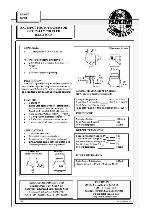
SZ6043中文资料
IS604中文资料
-2.0
-1.0
0
1.0
2.0
Forward voltage VF ( V ) Normalised Output Current vs. Ambient Temperature 2.4 2.2 2.0 1.8 1.6 1.4 1.2 1.0 0.8 0.6 0.4 0.2 0 -30 0 25 50 75 Ambient temperature TA ( °C ) Normalised Output Current vs. Forward Current 5 1 0.5 0.1 0.05 0.01 0.005 Normalised to VCE = 10V , IF = ±10mA , TA = 25°C 100 Normalised to VCE = 10V , IF = ±10mA , RBE = 1MΩ , TA = 25°C IF = ±20mA
7/12/00
DB92264-AAS/A2
Collector Power Dissipation vs. Ambient Temperature 400 Collector power dissipation P C (mW) 100 80 Forward current I F (±mA) 60 40 20 0 -20 -40 -60 -80 -100 -30 0 25 50 75 100 125
Output
V V V V nA %
Coupled
Collector-emitter Saturation VoltageVCE(SAT) Current Transfer Ratio Symmetry Input to Output Isolation Voltage VISO Input-output Isolation Resistance RISO Turn-on Time Turn-off Time Output Rise Time Output Fall Time ton toff tr tf 0.33 5300 7500 5x10¹⁰ 3 3 2 2
三汇示波器说明书(Ver1.0)
DST4000 和 DST1000 系列数字存储示波器用户手册
i
目录
5.1 显示区 ........................................................................................ 20 5.2 信息区域..................................................................................... 23 5.3 波形显示..................................................................................... 23
三汇系列产品
DST4000 和 DST1000 系列 数字存储示波器
Version 1.0
杭州三汇科技有限公司 www.
目录
目录
目 录 ...........................................................................................................i 版权申明 .......................................................................................................................................................................v 第 1 章 安全事项......................................................................................... 1
VFS6045型产品特性说明书

VFS6045SA102VFS6045SA151VFS6045SA451VFS6045VA031VFS6045VA102 VFS6045VA121VFS6045VA201VFS6045VA301E M C C o m p o n e n t sNoise suppression filterFor home appliances (conductive noise countermeasure) VFS seriesVFS6045 typeFEATURESAPPLICATIONPART NUMBER CONSTRUCTIONCHARACTERISTICS SPECIFICATION TABLEMeasurement equipmentEquivalent measurement equipment may be used.VFS6045V A031Series nameL×W×H dimensions V: at 10MHzS: at 1MHzInternal codeImpedance6.0×6.0×4.5 mm(Ω)Type Impedance DC resistance Rated current Part No.(Ω)Typ.(Ω)Min.(Ω)typ.(Ω)max.(A)max.6045VA[at 10MHz]57300.0120.0156 6.0VFS6045VA0311451200.0190.0247 5.1VFS6045VA1212422000.0230.0299 4.95VFS6045VA2014683000.0360.0468 3.6VFS6045VA301127510000.0750.0975 2.5VFS6045VA102 6045SA[at 1MHz]1881500.1750.2275 1.5VFS6045SA1515524500.470.6110.9VFS6045SA45112321000 1.15 1.4950.5VFS6045SA102Measurement item Product No.ManufacturerImpedance4294A Keysight T echnologiesDC resistance34420A Hewlett-PackardE M C C o m p o n e n t sVFS6045 typeZ FREQUENCY CHARACTERISTICSINSERTION LOSS VS. FREQUENCY CHARACTERISTICSE M C C o m p o n e n t s VFS6045 typeSHAPE & DIMENSIONSRECOMMENDED LAND PATTERNRECOMMENDED REFLOW PROFILEPACKAGING STYLETEMPERATURE RANGE, INDIVIDUAL WEIGHT *Operating temperature range includes self-temperature rise.**The storage temperature range is for after the assembly.Dimensions in mmDimensions in mmT ype A B KVFS6045 6.3 6.3 4.7Package quantity1500 pcs/reelOperating temperature range*Storagetemperature range**Individualweight–40 to +105 °C–40 to +105 °C0.6 gE M C C o m p o n e n t sREMINDERS FOR USING THESE PRODUCTSBefore using these products, be sure to request the delivery specifications.SAFETY REMINDERSPlease pay sufficient attention to the warnings for safe designing when using this products.The storage period is less than 12 months. Be sure to follow the storage conditions (temperature: 5 to 30°C, humidity: 10 to 75% RH or less).If the storage period elapses, the soldering of the terminal electrodes may deteriorate.Do not use or store in locations where there are conditions such as gas corrosion (salt, acid, alkali, etc.).Before soldering, be sure to preheat components.The preheating temperature should be set so that the temperature difference between the solder temperature and chip temperature does not exceed 150°C.Soldering corrections after mounting should be within the range of the conditions determined in the specifications.If overheated, a short circuit, performance deterioration, or lifespan shortening may occur.When embedding a printed circuit board where a chip is mounted to a set, be sure that residual stress is not given to the chip due to the overall distortion of the printed circuit board and partial distortion such as at screw tightening portions.Self heating (temperature increase) occurs when the power is turned ON, so the tolerance should be sufficient for the set thermal design.Carefully lay out the coil for the circuit board design of the non-magnetic shield type.A malfunction may occur due to magnetic interference.Use a wrist band to discharge static electricity in your body through the grounding wire.Do not expose the products to magnets or magnetic fields.Do not use for a purpose outside of the contents regulated in the delivery specifications.The products listed on this catalog are intended for use in general electronic equipment (AV equipment, telecommunications equip-ment, home appliances, amusement equipment, computer equipment, personal equipment, office equipment, measurement equip-ment, industrial robots) under a normal operation and use condition.The products are not designed or warranted to meet the requirements of the applications listed below, whose performance and/or qual-ity require a more stringent level of safety or reliability, or whose failure, malfunction or trouble could cause serious damage to society,person or property.If you intend to use the products in the applications listed below or if you have special requirements exceeding the range or conditions set forth in the each catalog, please contact us.(1) Aerospace/aviation equipment(2) T ransportation equipment (cars, electric trains, ships, etc.)(3) Medical equipment(4) Power-generation control equipment (5) Atomic energy-related equipment (6) Seabed equipment(7) T ransportation control equipment(8) Public information-processing equipment (9) Military equipment(10) Electric heating apparatus, burning equipment (11) Disaster prevention/crime prevention equipment(12) Safety equipment(13) Other applications that are not considered general-purposeapplicationsWhen designing your equipment even for general-purpose applications, you are kindly requested to take into consideration securing pro-tection circuit/device or providing backup circuits in your equipment.REMINDERSVFS6045SA102VFS6045SA151VFS6045SA451VFS6045VA031VFS6045VA102 VFS6045VA121VFS6045VA201VFS6045VA301。
世伟洛克 40G,40,60,83系列 和 AFS 球阀 说明书
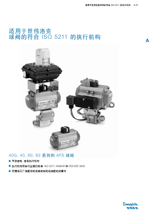
适用于世伟洛克球阀的符合 ISO 5211 的执行机构 A-97A40G, 40, 60, 83 系列和 AFS 球阀■ 气动齿轮、齿条执行机构■ 执行机构符合行业接口标准:ISO 5211, NAMUR 和 VDI/VDE 3845■ 可提供工厂装配好的成品或供现场装配的成套件适用于世伟洛克球阀的符合 ISO 5211 的执行机构A-98 球阀A符合 ISO 5211 的世伟洛克齿条和齿轮气动执行机构适用于一般应用。
提供直通阀和角型阀用弹簧回程和双作用模式的产品。
世伟洛克可提供符合 ISO 5211、NAMUR 和 VDI/VDE 3845 接口标准的带全部执行机构的球阀组件、包括阀门、执行机构、传感器、支架成套件和电磁阀。
本产品目录所列阀门执行机构组件的设计条件是:■ 最高阀门压力■ 环境温度 (10 到 37°C [50 到100°F])■ 设计余量为计算操作扭矩的 20%。
欲获得关于阀门操作扭矩计算的更多信息、请参阅世伟洛克带执行机构的球阀选型指南、符合 ISO 5211 的执行机构安装支架成套件、P A-105。
执行机构工作额定值最大的执行机构压力是 116 psig (8 .0 bar)。
证书对于工厂装配的符合 ISO 5211 的世伟洛克执行机构、可在订单报价时要求提供 ATEX 认证。
现场装配不提供 ATEX 认证。
执行机构结构材料还可以提供更多材料。
请联系您的授权世伟洛克代表。
执行机构安装支架阀门阀门接地弹簧电磁阀安装支架位置指示器接头阀杆螺母锁定片固定螺钉接头面板螺母40G, 40, 83, H83 系列AFS 球阀60 系列 4 螺栓铸造不锈钢墙壁安装支架六角螺栓有头螺钉六角 螺母锁紧垫圈符合 ISO 5211 标准的气动执行机构适用于世伟洛克球阀的符合 ISO 5211 的执行机构 A-99A40G 和 40 系列阀门关于阀门特点、结构材料和技术数据、请参阅世伟洛克产品目录一体式仪表球阀—40G系列和 40 系列, P A-3。
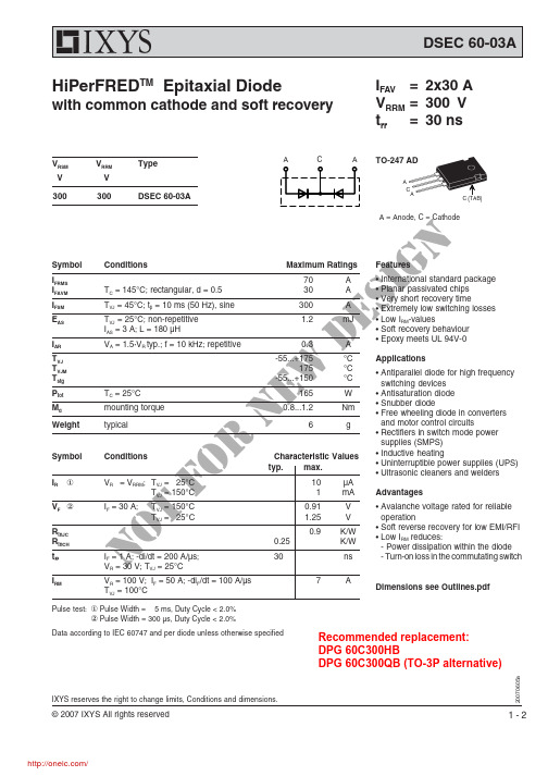
DSEC60-03A;中文规格书,Datasheet资料
Conditions
or VR = VRRM; TVJ = 25°C TVJ = 150°C
f IF = 30 A; TVJ = 150°C
TVJ = 25°C
ot IF = 1 A; -di/dt = 200 A/µs; NVR = 30 V; TVJ = 25°C
10
µA
1 mA Advantages
0.91
V
• Avalanche voltage rated for reliable
1.25
V
operation
0.25
0.9
K/W K/W
• Soft reverse recovery for low EMI/RFI • Low IRM reduces:
- Power dissipation within the diode
.+175
°C
175
°C
-55...+150
°C
w165
W
e0.8...1.2
Nm
n6
g
Applications
• Antiparallel diode for high frequency switching devices
• Antisaturation diode • Snubber diode • Free wheeling diode in converters
DSEC 60-03A
HiPerFREDTM Epitaxial Diode
with common cathode and soft recovery
IFAV = 2x30 A VRRM = 300 V trr = 30 ns
飞扬电子产品选型手册说明书

在开始使用前请仔细阅读下面说明概述飞扬电子主要是销售信号采集,控制卡的公司,主要从事的行业是测控行业。
目前已有的产品包括PCI 总线,PCIe总线,USB总线,串口等等。
保修用户需要遵守储存、运输和使用的要求。
因违反操作规定和要求而造成损坏的,需缴纳器件费和维修费及相应的运输费用,如果板卡有明显烧毁、烧糊情况原则上不予维修。
保修期:一年。
具体的维修细则请参看产品的手册附录。
版权信息保留在不另行通知的情况下,更新手册的权利。
不承担由于使用产品不当,所造成的直接、间接、附带的或相应产生的损失或责任。
本产品及其软件具有专利权、版权及其他知识产权。
未经授权,不得直接或间接复制、制造、加工本产品及其相关部分。
应用范围本产品设计制造由于普通工业应用,不能用于易燃易爆等危险场合,超于预料的用途或对人的生命或财产造成重大影响的场合不在本产品应用和服务的范围内。
软件支持服务终身提供技术支持。
目录在开始使用前请仔细阅读下面说明 (1)一、概述 (3)1.1 产品信息 (3)1.2 使用流程 (4)1.3 选型建议 (4)1.4 产品优势 (6)二、主要产品展示 (7)FY2400 (7)FY2450 (8)FY4400 (9)FY4401 (10)FY4405 (11)FY6400 (12)FY6402 (13)FY6403 (14)FY6405 (15)FY6451 (16)FY5400 (17)FY5402 (18)FY5403 (19)FY5405 (20)FY5451 (21)FY3400 (22)FY3401 (23)FY3402 (24)FY3403 (25)FY3404 (26)FY3405 (27)FY3406 (28)FY3451 (29)三、用户注意事项 (30)四、版本信息 (31)一、概述1.1 产品信息简介本公司的IO (开关量/数字量)控制板卡,是实现自动化控制的基础设备。
产品按照总线可以分为:PCI总线;PCIe 总线;USB 总线;RS232总线控制卡是在工业控制领域,自动化集成设备中应用的一种电子设备。
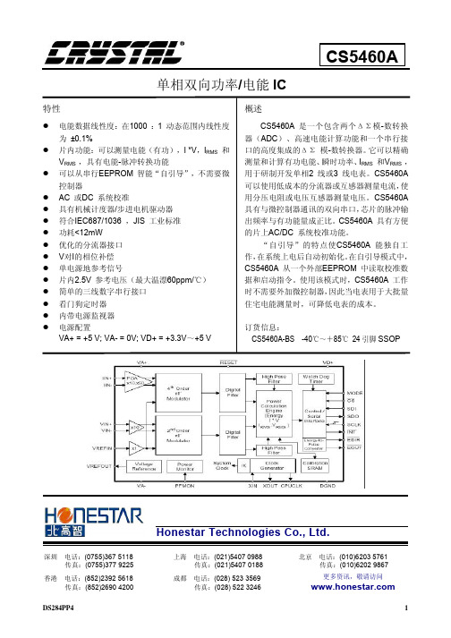
CS5463A中文资料手册pdf
TPS604中文资料

SLVS324 - 2001年7月功能∙反转输入电压∙高达60 mA的输出电流∙只有三个小1 - μF陶瓷电容器的∙输入电压范围从1.6 V至5.5 V,∙省电模式在低输出电流(TPS60400),以提高效率∙器件的静态电流典型的100 μ∙综合活动肖特基二极管应用•LCD偏置∙砷化镓射频功率放大器的偏置∙便携式仪器在传感器电源∙双极放大器的电源∙医疗器械∙电池供电设备DBV封装(顶视图)CFLY +接地启动进入负载输出∙小型5引脚SOT23封装中•评估模块TPS60400EVM-178CFLY-描述TPS6040x是一个不受管制的负输出电压的输入电压范围从1.6 V至5.5 V的设备通常是由一个5 V或3.3 preregulated电源轨五,由于它的宽输入电压范围提供了设备产生的家庭,两个或三个镍镉电池,镍氢电池或碱性电池,以及一个锂离子电池功率他们还可以。
只有三个外部1 - μ F电容需要建立一个完整的电荷泵DC / DC逆变器。
5引脚SOT23封装,组装,完整的转换器,可建50毫米2的电路板面积。
额外的电路板面积和减少元件数量达到取代肖特基二极管通常需要启动到集成电路的负载。
TPS6040x可提供的最大输出电流60毫安的典型转换效率大于90%以上的宽输出电流范围。
20千赫,50千赫,250 kHz固定频率操作设备三个选项可供选择。
一个装置带有一个可变开关频率,以降低工作电流在一个宽负载范围内的应用,使价值低电容设计。
典型应用电路TPS6040 0的输出VOLTAG é V S 输入电压产量-1.6 V至-5V,最大60 mA至五Ø -输出电压- V的-1-2-3-4-5012345VI - 输入电压- V的请注意,一个重要的通知有关可用性,标准保修,并使用在关键应用德州仪器公司的半导体产品和免责条款及其出现在此数据表的结束。
版权所有© 2001年,德州仪器生产数据信息是当前出版日期。
TPS60401

Figure 21t − Time − µsV I = 5 V I O = 30 mATPS60402TPS6040150 mV/DIV50 mV/DIV20 µs/DIV Figure 22TPS60400, TPS60403OUTPUT VOLTAGEt − Time − µsV I = 5 V I O = 30 mATPS60403TPS60400100 mV/DIV50 mV/DIV4 µs/DIVCFLYC I NC O U TU1TPS60400IN GND Figure 37. Recommended PCB Layout for TPS6040x (top layer)device family productsOther inverting dc-dc converters from Texas Instruments are listed in Table 5.Table 5. Product IdentificationPART NUMBERTPS6735Fixed negative 5TPS6755Adjustable 1-W inverting dc-dc converterPACKAGING INFORMATION(1) The marketing status values are defined as follows:ACTIVE: Product device recommended for new designs.Addendum-Page 1LIFEBUY: TI has announced that the device will be discontinued, and a lifetime-buy period is in effect.NRND: Not recommended for new designs. Device is in production to support existing customers, but TI does not recommend using this part in a new design.PREVIEW: Device has been announced but is not in production. Samples may or may not be available.OBSOLETE: TI has discontinued the production of the device.(2) Eco Plan - The planned eco-friendly classification: Pb-Free (RoHS), Pb-Free (RoHS Exempt), or Green (RoHS & no Sb/Br) - please check /productcontent for the latest availability information and additional product content details.TBD: The Pb-Free/Green conversion plan has not been defined.Pb-Free (RoHS): TI's terms "Lead-Free" or "Pb-Free" mean semiconductor products that are compatible with the current RoHS requirements for all 6 substances, including the requirement that lead not exceed 0.1% by weight in homogeneous materials. Where designed to be soldered at high temperatures, TI Pb-Free products are suitable for use in specified lead-free processes.Pb-Free (RoHS Exempt): This component has a RoHS exemption for either 1) lead-based flip-chip solder bumps used between the die and package, or 2) lead-based die adhesive used between the die and leadframe. The component is otherwise considered Pb-Free (RoHS compatible) as defined above.Green (RoHS & no Sb/Br): TI defines "Green" to mean Pb-Free (RoHS compatible), and free of Bromine (Br) and Antimony (Sb) based flame retardants (Br or Sb do not exceed 0.1% by weight in homogeneous material)(3) MSL, Peak Temp. -- The Moisture Sensitivity Level rating according to the JEDEC industry standard classifications, and peak solder temperature.(4) Multiple Top-Side Markings will be inside parentheses. Only one Top-Side Marking contained in parentheses and separated by a "~" will appear on a device. If a line is indented then it is a continuation of the previous line and the two combined represent the entire Top-Side Marking for that device.Important Information and Disclaimer:The information provided on this page represents TI's knowledge and belief as of the date that it is provided. TI bases its knowledge and belief on information provided by third parties, and makes no representation or warranty as to the accuracy of such information. Efforts are underway to better integrate information from third parties. TI has taken and continues to take reasonable steps to provide representative and accurate information but may not have conducted destructive testing or chemical analysis on incoming materials and chemicals. TI and TI suppliers consider certain information to be proprietary, and thus CAS numbers and other limited information may not be available for release.In no event shall TI's liability arising out of such information exceed the total purchase price of the TI part(s) at issue in this document sold by TI to Customer on an annual basis.OTHER QUALIFIED VERSIONS OF TPS60400, TPS60401, TPS60402, TPS60403 :•Automotive: TPS60400-Q1, TPS60401-Q1, TPS60402-Q1, TPS60403-Q1NOTE: Qualified Version Definitions:•Automotive - Q100 devices qualified for high-reliability automotive applications targeting zero defectsAddendum-Page 2TAPE AND REEL INFORMATION*All dimensions are nominal Device Package Type Package DrawingPinsSPQ Reel Diameter (mm)Reel Width W1(mm)A0(mm)B0(mm)K0(mm)P1(mm)W (mm)Pin1Quadrant TPS60400DBVR SOT-23DBV 53000180.09.0 3.15 3.2 1.4 4.08.0Q3TPS60400DBVR SOT-23DBV 53000178.09.0 3.23 3.17 1.37 4.08.0Q3TPS60400DBVT SOT-23DBV 5250178.09.0 3.23 3.17 1.37 4.08.0Q3TPS60400DBVT SOT-23DBV 5250180.09.0 3.15 3.2 1.4 4.08.0Q3TPS60401DBVR SOT-23DBV 53000178.09.0 3.23 3.17 1.37 4.08.0Q3TPS60401DBVR SOT-23DBV 53000180.09.0 3.15 3.2 1.4 4.08.0Q3TPS60401DBVT SOT-23DBV 5250180.09.0 3.15 3.2 1.4 4.08.0Q3TPS60401DBVT SOT-23DBV 5250178.09.0 3.23 3.17 1.37 4.08.0Q3TPS60402DBVR SOT-23DBV 53000180.09.0 3.15 3.2 1.4 4.08.0Q3TPS60402DBVR SOT-23DBV 53000178.09.0 3.23 3.17 1.37 4.08.0Q3TPS60402DBVT SOT-23DBV 5250178.09.0 3.23 3.17 1.37 4.08.0Q3TPS60402DBVT SOT-23DBV 5250180.09.0 3.15 3.2 1.4 4.08.0Q3TPS60403DBVR SOT-23DBV 53000180.09.0 3.15 3.2 1.4 4.08.0Q3TPS60403DBVR SOT-23DBV 53000178.09.0 3.23 3.17 1.37 4.08.0Q3TPS60403DBVT SOT-23DBV 5250178.09.0 3.23 3.17 1.37 4.08.0Q3TPS60403DBVT SOT-23DBV 5250180.09.0 3.15 3.2 1.4 4.08.0Q3*All dimensions are nominalDevice Package Type Package Drawing Pins SPQ Length(mm)Width(mm)Height(mm) TPS60400DBVR SOT-23DBV53000182.0182.020.0 TPS60400DBVR SOT-23DBV53000180.0180.018.0 TPS60400DBVT SOT-23DBV5250180.0180.018.0 TPS60400DBVT SOT-23DBV5250182.0182.020.0 TPS60401DBVR SOT-23DBV53000180.0180.018.0 TPS60401DBVR SOT-23DBV53000182.0182.020.0 TPS60401DBVT SOT-23DBV5250182.0182.020.0 TPS60401DBVT SOT-23DBV5250180.0180.018.0 TPS60402DBVR SOT-23DBV53000182.0182.020.0 TPS60402DBVR SOT-23DBV53000180.0180.018.0 TPS60402DBVT SOT-23DBV5250180.0180.018.0 TPS60402DBVT SOT-23DBV5250182.0182.020.0 TPS60403DBVR SOT-23DBV53000182.0182.020.0 TPS60403DBVR SOT-23DBV53000180.0180.018.0 TPS60403DBVT SOT-23DBV5250180.0180.018.0TPS60403DBVT SOT-23DBV5250182.0182.020.0IMPORTANT NOTICETexas Instruments Incorporated and its subsidiaries(TI)reserve the right to make corrections,enhancements,improvements and other changes to its semiconductor products and services per JESD46,latest issue,and to discontinue any product or service per JESD48,latest issue.Buyers should obtain the latest relevant information before placing orders and should verify that such information is current and complete.All semiconductor products(also referred to herein as“components”)are sold subject to TI’s terms and conditions of sale supplied at the time of order acknowledgment.TI warrants performance of its components to the specifications applicable at the time of sale,in accordance with the warranty in TI’s terms and conditions of sale of semiconductor products.Testing and other quality control techniques are used to the extent TI deems necessary to support this warranty.Except where mandated by applicable law,testing of all parameters of each component is not necessarily performed.TI assumes no liability for applications assistance or the design of Buyers’products.Buyers are responsible for their products and applications using TI components.To minimize the risks associated with Buyers’products and applications,Buyers should provide adequate design and operating safeguards.TI does not warrant or represent that any license,either express or implied,is granted under any patent right,copyright,mask work right,or other intellectual property right relating to any combination,machine,or process in which TI components or services are rmation published by TI regarding third-party products or services does not constitute a license to use such products or services or a warranty or endorsement e of such information may require a license from a third party under the patents or other intellectual property of the third party,or a license from TI under the patents or other intellectual property of TI.Reproduction of significant portions of TI information in TI data books or data sheets is permissible only if reproduction is without alteration and is accompanied by all associated warranties,conditions,limitations,and notices.TI is not responsible or liable for such altered rmation of third parties may be subject to additional restrictions.Resale of TI components or services with statements different from or beyond the parameters stated by TI for that component or service voids all express and any implied warranties for the associated TI component or service and is an unfair and deceptive business practice. TI is not responsible or liable for any such statements.Buyer acknowledges and agrees that it is solely responsible for compliance with all legal,regulatory and safety-related requirements concerning its products,and any use of TI components in its applications,notwithstanding any applications-related information or support that may be provided by TI.Buyer represents and agrees that it has all the necessary expertise to create and implement safeguards which anticipate dangerous consequences of failures,monitor failures and their consequences,lessen the likelihood of failures that might cause harm and take appropriate remedial actions.Buyer will fully indemnify TI and its representatives against any damages arising out of the use of any TI components in safety-critical applications.In some cases,TI components may be promoted specifically to facilitate safety-related applications.With such components,TI’s goal is to help enable customers to design and create their own end-product solutions that meet applicable functional safety standards and requirements.Nonetheless,such components are subject to these terms.No TI components are authorized for use in FDA Class III(or similar life-critical medical equipment)unless authorized officers of the parties have executed a special agreement specifically governing such use.Only those TI components which TI has specifically designated as military grade or“enhanced plastic”are designed and intended for use in military/aerospace applications or environments.Buyer acknowledges and agrees that any military or aerospace use of TI components which have not been so designated is solely at the Buyer's risk,and that Buyer is solely responsible for compliance with all legal and regulatory requirements in connection with such use.TI has specifically designated certain components as meeting ISO/TS16949requirements,mainly for automotive use.In any case of use of non-designated products,TI will not be responsible for any failure to meet ISO/TS16949.Products ApplicationsAudio /audio Automotive and Transportation /automotiveAmplifiers Communications and Telecom /communicationsData Converters Computers and Peripherals /computersDLP®Products Consumer Electronics /consumer-appsDSP Energy and Lighting /energyClocks and Timers /clocks Industrial /industrialInterface Medical /medicalLogic Security /securityPower Mgmt Space,Avionics and Defense /space-avionics-defense Microcontrollers Video and Imaging /videoRFID OMAP Applications Processors /omap TI E2E Community Wireless Connectivity /wirelessconnectivityMailing Address:Texas Instruments,Post Office Box655303,Dallas,Texas75265Copyright©2013,Texas Instruments Incorporated。
世伟洛克-球阀60系列
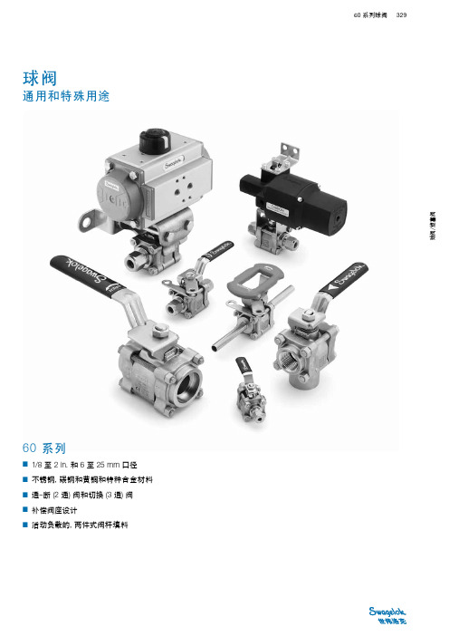
加强型 PTFE ➃ 应变硬化 316 SS / A167 或 A240 碳氟 FKM ➆
WCB ➄ / A216
黄铜 CDA 360 / B16
镀镉碳钢等级 8 / SAE J429➇ 镀镉碳钢等级 8 / SAE J995➈
硅脂基和 PTFE 基润滑剂;可提供其他的润滑剂
润湿元件用 斜体 表示。 ➀ 可供应的特种合金材料包括合金 400, 合金 C-276, 合金 20, 合金 600 和钛。 请联系您当地的世伟洛克授权销售和服务代表。 ➁ 62 系列—没有与手柄结合在一起的上阀杆弹簧和止动板。 ➂ 装 有气动执行器的阀带有一锁定片(未示出)以将螺母固定在阀杆上。 ➃ 其他可供应的材料; 见 合金 X-750—2 个支撑; PEEK—1 个支撑。 ➆ 其他可供应的材料; 见成套密封法兰, P 336。 ➇ 62 系列—材料规格是 ASTM A574。 ➈ 62 系列—螺母是等级 4130 或 4140/ASTM A322 或 A331。
AD9273BSVZ-50;AD9273BSVZ-25;AD9273BBCZ-25;AD9273BSVZ-40;AD9273BBCZ-40;中文规格书,Datasheet资料

/
CLK+ CLK–
AD9273 TABLE OF CONTENTS
Features .............................................................................................. 1 Applications ....................................................................................... 1 General Description ......................................................................... 1 Functional Block Diagram .............................................................. 1 Revision History ............................................................................... 2 Product Highlights ........................................................................... 3 Specifications..................................................................................... 4 AC Specifications.......................................................................... 4 Digital Specifications ................................................................... 8 Switching Specifications .............................................................. 9 ADC Timing Diagrams ................................................................. 10 Absolute Maximum Ratings.......................................................... 11 Thermal Impedance ................................................................... 11 ESD Caution ................................................................................ 11 Pin Configuration and Function Descriptions ........................... 12 Typical Performance Characteristics ........................................... 15 Equivalent Circuits ......................................................................... 19 Theory of Operation ...................................................................... 21 Ultrasound .................................................................................. 21 Channel Overview ..................................................................... 22 Input Overdrive .......................................................................... 25 CW Doppler Operation............................................................. 25 TGC Operation ........................................................................... 27 ADC ............................................................................................. 31 Clock Input Considerations ...................................................... 31 Serial Port Interface (SPI) .............................................................. 38 Hardware Interface..................................................................... 38 Memory Map .................................................................................. 40 Reading the Memory Map Table .............................................. 40 Reserved Locations .................................................................... 40 Default Values ............................................................................. 40 Logic Levels ................................................................................. 40 Outline Dimensions ....................................................................... 44 Ordering Guide .......................................................................... 45
iec 60404-3—2010
IEC xxx-3—2010 是国际电工委员会(International Electrotechnical Commission,简称IEC)下的标准之一,是关于不同类型磁性材料的一致标准规范。
本文将对该标准的主要内容进行介绍,并探讨其在工程实践中的应用。
一、标准的背景与意义IEC xxx-3—2010 标准是磁性材料领域的一项重要规范,它为不同类型的磁性材料提供了统一的测试方法和技术要求。
作为全球范围内的统一标准,IEC xxx-3—2010 的制定旨在提高磁性材料的质量和性能,并促进国际间的技术交流和合作。
通过该标准的实施,能够有效减少各地各家生产厂家之间因技术标准不统一而导致的交流障碍和信息不对称,进而有利于推动磁性材料行业的持续发展和进步。
二、标准的内容和主要技术要求IEC xxx-3—2010 标准主要包括以下几个方面的内容和技术要求:1. 术语和定义:对磁性材料领域中常用的术语和定义进行了规范和解释,以便在标准的实施过程中能够达成共识,减少术语误解和交流困难。
2. 符号和标记:规定了磁性材料在生产、使用和销售过程中所应使用的符号和标记,有利于统一行业标准,提高产品识别和交流效率。
3. 测量方法:详细介绍了对不同类型磁性材料的磁性能参数进行测量和测试的方法和技术要求,包括磁化曲线的测量、磁滞回线的测量、铁磁材料的磁化强度测量等。
4. 技术要求:针对不同类型的磁性材料,规定了其在磁化性能、磁化损耗、磁滞回线等方面的技术要求和限制值,以确保其符合国际标准和行业规范。
三、标准的应用和推广IEC xxx-3—2010 标准作为国际电工委员会下的一项重要规范,在全球范围内得到了广泛的应用和推广。
该标准为生产厂家提供了统一的测试方法和技术要求,使得不同厂家生产的磁性材料可以进行公正的比较和评价,有效提升了产品质量和性能。
IEC xxx-3—2010 的实施有助于促进国际间的技术交流和合作,推动磁性材料行业的全球化发展。
施耐德SH3 系列伺服电机产品手册_V202_ZH

dd.mm.yyyy
14
I0 0.00 Arms Nmax 0000 rpm nN 0000 rpm IPxx(xx)
15
UN 000 Vrms
Ubr rmo PTC
Pbr 0 W
Th-CI F DT-F2 E208613
Mbr 0 Nm
17
18
Made in Germany
2
伺服电机
0198441113991, V2.02, 10.2012
SH3
目录
重要说明 目录 关于本手册 1 序言 1.1 电机系列 1.2 可选件和配件 1.3 铭牌 1.4 型号代码 2 开始之前 - 安全信息 2.1 操作人员资质 2.2 指定用途 2.3 危险等级 2.4 基本信息 2.5 标准和术语 3 技术参数 3.1 常规属性 3.2 特定电机数据
9.2 术语和缩写
4
SH3
53
53
55
57 59
60 60 63 69
71
73
73
73
75
75
75
76 76 77 78 79
80
81
81
81
81
83
83
85
85 85 85 85 85 86 86 86 86 86
87
伺服电机
0198441113991, V2.02, 10.2012
SH3
10 图表目录 11 关键字索引
类型 00 = 标准
1) 仅在特定电机型号时可用,参见"3.2 特定电机数据"一章。 2) 本手册中仅对此处列明的规格做出说明。 3) 安装位置为 IM V3(立式驱动轴,轴末端朝上)时只能达到防护等级 IP50。 4) 硬件版本 ≥RS03: 可连接压缩空气,以达到 IP67。参见章节 "4.4.1 压缩空气连接"。 5) 可连接压缩空气,以达到 IP67。参见章节 "4.4.1 压缩空气连接"。
tps60403工作原理

TPS60403是一款高效、紧凑的电源管理IC,广泛应用于各类电子设备中。
以下是TPS60403的工作原理,主要包含电压调节、电流限制、反馈回路、启动与关机、软启动、故障保护、自动恢复和热管理等方面。
一、电压调节TPS60403具有出色的电压调节功能,能够确保输出电压的稳定。
它采用先进的反馈机制,实时监测输出电压,并根据需要进行调整,以保持电压的恒定。
二、电流限制为了保护电路和负载免受过电流的损害,TPS60403内置了过电流保护功能。
当电流超过预设的安全阈值时,TPS60403会自动降低输出功率,以减小电流,确保电路和负载的安全。
三、反馈回路反馈回路是TPS60403的重要功能之一。
它通过采样输出电压和电流,将信号反馈至IC内部,经过处理后调整输出电压或电流,以确保电源性能的稳定。
这种反馈机制有助于减小输出电压和电流的误差,提高电源的精度和可靠性。
四、启动与关机TPS60403具有灵活的启动与关机控制功能。
通过特定的控制信号,可以启动或关闭IC的工作。
在启动过程中,TPS60403采用软启动技术,逐步增加输出电压,以减小启动瞬间的电流冲击。
在关机状态下,TPS60403将关闭输出,进入低功耗状态。
五、软启动为了减小启动瞬间的电流冲击,TPS60403采用了软启动技术。
在启动过程中,IC逐步增加输出电压,以平滑过渡至正常工作状态。
软启动功能有助于减小对电路和负载的冲击,提高电源的可靠性。
六、故障保护为了确保电源的安全运行,TPS60403具备多种故障保护功能。
当检测到过电压、过电流、过热等异常情况时,TPS60403会自动进入保护状态,通过降低输出功率或关闭输出等方式来减小对电路和负载的损害。
同时,TPS60403还会通过故障指示灯或其他通信接口报告故障信息,以便及时进行维护和处理。
七、自动恢复当故障解除后,TPS60403具备自动恢复功能。
它能够自动检测到异常状态的解除,并逐步恢复至正常工作状态。
sh39f003规格书
sh39f003规格书
SH39F003是一款具有高性能和多功能的集成电路。
其规格书提供了该芯片的
详细技术参数和功能描述,以便用户了解并使用此产品。
该规格书包含以下几个主要部分:
1. 引脚功能描述:该芯片具有多个引脚,规格书提供了每个引脚的具体功能和
连接要求,以便用户正确地连接该芯片。
2. 电气特性:规格书列出了SH39F003的电气参数,包括工作电压范围、功耗、输入/输出电平要求等。
这些参数对于设计电路和保证正常工作是非常重要的。
3. 时序图:规格书提供了SH39F003的时序图,展示了不同信号之间的时序关
系和时钟要求。
这些信息对于用户了解该芯片的数据传输和时钟同步是至关重要的。
4. 功能描述:规格书详细描述了SH39F003的功能和特性。
它包括内部结构、
工作模式、数据处理能力等。
用户可以根据这些信息评估芯片是否适合他们的应用需求。
5. 包装和引脚布局:规格书提供了SH39F003的包装信息和引脚布局图。
这对
于用户在PCB设计和组装过程中起到一定的指导作用。
SH39F003规格书是设计工程师、电子爱好者和制造商的重要参考文档。
通过
阅读并理解该规格书,用户可以更好地使用和集成SH39F003芯片,以满足他们的
设计需求。
株洲市天元区初一下册历史试卷
MSOX3054A手册引言概述在现代电子测量技术领域,示波器是一种关键的仪器,广泛应用于电子工程、通信、医疗等领域。
MSOX3054A是Keysight推出的一款先进示波器,具有出色的性能和功能。
本文将深入探讨MSOX3054A示波器的使用手册,以帮助用户充分理解并有效地利用这一高性能设备。
正文内容1. 产品概述1.1 型号及规格首先,MSOX3054A示波器是Keysight InfiniiVision系列的一部分,是一款四通道示波器。
该型号的规格包括带宽、采样率、存储深度等重要参数。
详细了解这些规格有助于用户充分了解设备的性能范围,以便在实际应用中更好地选择和配置。
1.2 基本操作和控件手册中通常包含有关设备的基本操作指南和各种控制面板的详细说明。
用户可以通过阅读手册更深入地了解示波器的控制面板布局、按钮功能和菜单选项。
这有助于提高用户对设备操作的熟练程度,从而更高效地进行测量和分析。
1.3 连接和接口MSOX3054A示波器通常提供多种连接和接口选项,例如USB、LAN、GPIB等。
手册中会介绍如何正确连接示波器到计算机或其他仪器,以及如何通过这些接口进行数据传输。
这对于用户在实际应用中建立合适的测量系统非常重要。
2. 测量和分析功能2.1 波形测量手册会详细介绍示波器的波形测量功能,包括幅值、频率、相位等参数的测量方法。
此外,手册可能会提供一些高级测量功能,例如谱分析、脉冲测量等。
深入了解这些测量功能有助于用户在实际应用中准确捕捉和分析电信号。
2.2 存储和回放MSOX3054A示波器通常配备了大容量的存储器,使用户能够捕捉和保存长时间的信号波形。
手册中会介绍存储和回放功能的具体操作步骤,以及如何有效地管理和导出存储的数据。
这对于需要长时间监测和分析信号的用户非常重要。
2.3 自动化和脚本对于需要进行重复性测量或自动化测试的用户,手册中通常包含有关脚本编写和自动化操作的信息。
了解如何编写和运行脚本可以极大提高测试的效率和准确性。
Belimo F6350-300SHP 350型号三极阀门数据表
F6350-300SHP•Butterfly Valve with Lug typesReinforced Teflon Seat, 316 Stainless SteelType overviewType DNF6350-300SHP350 Technical dataFunctional data Valve size [mm]14" [350]Fluid chilled or hot water, up to 60% glycol, steamFluid Temp Range (water)-22...400°F [-30...204°C]Body Pressure Rating ANSI Class 300Flow characteristic modified equal percentage, unidirectionalServicing maintenance-freeFlow Pattern2-wayLeakage rate0%Controllable flow range quarter turn, mechanically limitedCv6857Maximum Inlet Pressure (Steam)50 psiMaximum Velocity32 FPSLug threads 1 1/8-8 UNCMaterials Valve body Carbon steel full lug (ASME B16.34)Stem17-4 PH stainless steelSeat RPTFEPipe connection ASME/ANSI class 300 flangeBearing glass backed PTFEDisc316 stainless steelGear operator materials Gears - hardened steelSuitable actuators Non-Spring SY5SY7SY8Safety notesWARNING: This product can expose you to lead which is known to the State of California tocause cancer and reproductive harm. For more information go to F6350-300SHP Product featuresFlow/Mounting detailsDimensionsType DN WeightF6350-300SHP350290 lb [130 kg]A B C D E F Number of Bolt Holes11.5" [293] 4.6" [118]47.7" [1212]33.3" [846]11.1" [282]11.1" [282]20F6350-300SHPA B C D E F Number of Bolt Holes12.6" [320] 3.2" [82]43.9" [1116]32.8" [834]11.1" [282]11.1" [282]20SY7-110On/Off, Floating point, Non fail-safe, 120 VTechnical dataElectrical data Nominal voltage AC 120 VNominal voltage frequency50/60 HzNominal voltage range AC 96...132 VTransformer sizing504 VACurrent consumption 4.2 AAuxiliary switch2x SPDT, 1 mA...5 A (3 A inductive), DC 5 V...AC250 V, 1 x 3° / 1 x 87°Switching capacity auxiliary switch 1 mA...5 A (3 A inductive), DC 5 V...AC 250 VElectrical Connection Terminal blocksOverload Protection thermally protected 135°C cut-outInternal Humidty Control resistive heating elementFunctional data Torque motor1000 NmDirection of motion motor selectable with switch 0/1Manual override hand wheelAngle of rotation90°Running Time (Motor)50 sDuty cycle value30%Noise level, motor45 dB(A)Position indication top mounted domed indicatorSafety data Degree of protection IEC/EN IP66/67Degree of protection NEMA/UL NEMA 4XEnclosure UL Enclosure Type 4XAgency Listing ISO, CE, cCSAusQuality Standard ISO 9001Ambient humidity Max. 100% RHAmbient temperature-22...149°F [-30...65°C]Storage temperature-40...176°F [-40...80°C]Servicing maintenance-freeWeight Weight46 lb [21 kg]Materials Housing material die cast aluminiumGear train high alloy steel gear sets, self lockingSY7-110ApplicationProduct featuresSY Series actuators are fractional horsepower devices, and utilize full-wave power supplies. Observe wire sizing and transformer sizing requirements. Proportional models CANNOT be connected to Belimo direct coupled (AF, AM, GM…etc) actuator power supplies or any type of half-wave device. You MUST use a separate, dedicated transformer or power supply to power the SY actuator. Please do not connect other automation equipment to the dedicated SY supply source. You MUST use four wires (plus a ground) to control a proportional control SY actuator (See SY Wiring Section).AccessoriesElectrical accessoriesDescriptionTypeLocal electric disconnect for SY4...12 series actuator, AC 120 V, on/off HOA-120VBattery backup system for SY7...12 series actuator, AC 120 V, on/offEXT-NSV-B05-120Electrical installationINSTALLATION NOTESDo not change sensitivity or dip switch setting with power applied.Power supply Common/Neutral and Control Signal "-"wiring to a common is prohibited.Terminals 4 and 6 need to be wired separately.Isolation relays must be used in parallel connection of multiple actuators using a commoncontrol signal inputs. The relays should be DPDT.Isolation relays are required in parallel applications. The reason parallel applications needisolation relays is that the motor uses two sets of windings, one for each direction. When one is energized to turn the actuator in a specific direction a voltage is generated in the other due to the magnetic field created from the first. It’s called back EMF. This is not an issue with one actuator because the voltage generated in the second winding isn’t connected to anything so there is no flow. On parallel applications without isolation, this EMF voltage energizes the winding it is connected to on the other actuators in the system, the actuators are tying to turn in both directions at once. The EMF voltage is always less than the supply voltage due to the resistance of the windings, so while the actuator still turns in the commanded direction, thedrag from the other reduces the torque output and causes overheating.Warning! Live electrical components!During installation, testing, servicing and troubleshooting of this product, it may be necessary to work with live electrical components. Have a qualified licensed electrician or other individual who has been properly trained in handling live electrical components perform these tasks. Failure to follow all electrical safety precautions when exposed to live electrical components could result in death or serious injury.SY7-110Wiring diagramsAC/DC 110/120 or 220/230VAC 110/120 or 220/230 VElectrical installation。
- 1、下载文档前请自行甄别文档内容的完整性,平台不提供额外的编辑、内容补充、找答案等附加服务。
- 2、"仅部分预览"的文档,不可在线预览部分如存在完整性等问题,可反馈申请退款(可完整预览的文档不适用该条件!)。
- 3、如文档侵犯您的权益,请联系客服反馈,我们会尽快为您处理(人工客服工作时间:9:00-18:30)。
SMB (DO-214AA)
4 .8 ± 0 .1 5
5 .4 ± 0 .15
1.1 ± 0 .3
2.0 ± 0.1 3.6 ± 0.1 5 2.3 ± 0.2
0.22 ± 0.07
MECHANICAL DATA
* * * * * * Case : SMB (DO-214AA) Molded plastic Epoxy : UL94V-O rate flame retardant Lead : Lead formed for Surface mount Polarity : Color band denotes cathode end Mounting position : Any Weight : 0.093 gram
Maximum DC Zener Current IZM (mA)
1440 1320 1220 1100 1010 930 856 790 765 700 630 580 545 520 475 430 395 365 340 315 295 280 265 250 237 216 198 190 176 170 158 144 132 122 110 100 93.0 86.0 79.0 76.0 70.0 63.0 58.0 54.5 52.5 47.5 43.0 39.5 36.6 34.0 31.6 29.4 28.0 26.4 25.0 23.6
Fig. 1 POWER TEMPERATURE DERATING CURVE PD, MAXIMUM DISSIPATION (WATTS)
5.0 4.0 3.0 2.0 1.0 0 0 25 50 75 100 125 150 175 5.0 mm2 ( 0.013 mm thick ) copper land areas.
Notes : ( 1 ) The type number listed have a standard tolerance on the nominal zener voltage of ± 10%, altered the fourth number of type from " 0 " for ± 10% tolerance to be " 5 " for ± 5.0% tolerance. ( 2 ) " SZ " will be omitted in marking on the diode.
T L, LEAD TEMPERATURE ( °C)
Page 1 of 2
Rev. 03 : March 25, 2005
元器件交易网
ELECTRICAL CHARACTERISTICS
Rating at 25 °C ambient temperature unless otherwise specified Nominal Zener Maximum Zener Voltage Impedance TYPE V Z @ IZT IZT Z ZT @ IZT ZZK @ IZK (V) (mA) (Ω) (Ω)
Dimensions in millimeter
MAXIMUM RATINGS
Rating at 25 °C ambient temperature unless otherwise specified
Rating
DC Power Dissipation at T L = 75 °C (Note1) Maximum Forward Voltage at I F = 1.0 A Junction Temperature Range Storage Temperature Range
Page 2 of 2
Rev. 03 : March 25, 2005
IZK (mA)
1.0 1.0 1.0 1.0 1.0 1.0 1.0 1.0 1.0 1.0 1.0 1.0 1.0 1.0 1.0 1.0 1.0 1.0 1.0 1.0 1.0 1.0 1.0 1.0 1.0 1.0 1.0 1.0 1.0 1.0 1.0 1.0 1.0 1.0 1.0 1.0 1.0 1.0 1.0 1.0 1.0 1.0 1.0 1.0 1.0 1.0 1.0 1.0 1.0 1.0 1.0 1.0 1.0 1.0 1.0 1.0
Symbol
PD VF TJ Ts
Value
5.0 1.2 - 55 to + 150 - 55 to + 150
Unit
W V °C °C
Note : (1) T L = Lead temperature at 5.0 mm2 ( 0.013 mm thick ) copper land areas.
Maximum Reverse Leakage Current IR @ V R (V) (µA)
300 150 150 150 150 150 150 150 150 150 150 150 150 150 150 50 2.0 1.0 1.0 1.0 1.0 0.5 0.5 0.5 0.5 0.5 0.5 0.5 0.5 0.5 0.5 0.5 0.5 0.5 0.5 0.5 0.5 0.5 0.5 0.5 0.5 0.5 0.5 0.5 0.5 0.5 0.5 0.5 0.5 0.5 0.5 0.5 0.5 0.5 0.5 0.5 1.0 1.0 1.0 1.0 1.0 1.0 2.0 3.0 4.0 4.9 5.4 5.9 6.3 6.6 7.2 8.0 8.6 9.4 10.1 10.8 11.5 12.2 13.0 13.7 14.4 15.8 17.3 18.0 19.4 20.1 21.6 23.8 25.9 28.1 31.0 33.8 36.7 40.3 43.0 44.6 49.0 54.0 59.0 63.0 65.5 72.0 79.2 86.4 93.2 101 108 115 122 130 137 144
元器件交易网
SZ603D - SZ60D0
VZ : 3.3 - 200 Volts PD : 5 Watts
FEATURES :
* Complete Voltage Range 3.3 to 200 Volts * High peak reverse power dissipation * High reliability * Low leakage current * Pb / RoHS Free
