SEW_compiler
SEW变频器程序修改方法
SEW变频器操作一、下载及上传方法:安装MOVITOOLS变频器程序编辑软件,目前安装的是V4.9版本。
运行MT-Manager,进入MANAGER画面,语言选择English,波特率为9.6KB,驱动类型选择Movidrive,连接方式(注意:直接连变频器选Inverter With Address,地址默认0;如果打开离线文件,选No Inverter)选Inverter With Address。
将SEW变频器连接器插入变频器,COM连接线连接上变频器与电脑,MANAGER 画面选择Update更新,选择出现的变频器编码,点击Shell,出现该变频器的程序界面(SHELL MOVITOOLS),选择屏幕上方的按钮,出现Copy Unit data数据传输界面,如果选择程序上传至电脑,From…中选择Inverter(Peer-to-peer中无需打对勾),To…中选择File,可重新选择路径和命名文件名;如果选择将电脑中的程序下载至变频器,From…中选择File,To…中选择Inverter。
二、离线修改参数:MANAGER中连接方式选择No Inverter,点击Shell,出现一个空的程序界面(SHELL MOVITOOLS),选择File—Open菜单打开需修改的程序,选择Startup-Startup菜单,打开参数设定界面,可按Start-up Set往下设定。
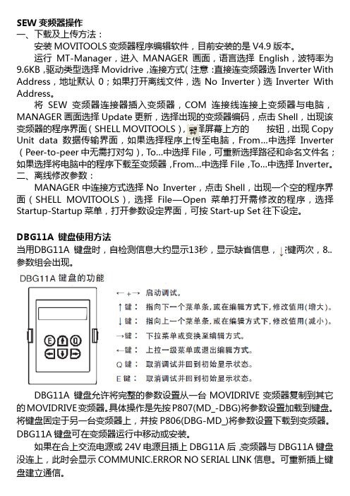
DBG11A 键盘使用方法当用DBG11A 键盘时,自检测信息大约显示13秒,显示缺省信息,按键两次,8..参数组会出现。
DBG11A 键盘允许将完整的参数设置从一台MOVIDRIVE变频器复制到其它的MOVIDRIVE变频器。
具体操作是先按P807(MD_-DBG)将参数设置加载到键盘。
将键盘固定于另一台变频器上,并按P806(DBG-MD_)将参数设置下载到变频器。
DBG11A 键盘可在变频器运行中移动或安装。
如果在合上交流电源或24V电源且插上DBG11A后,变频器与DBG11A键盘没连上,此时会显示COMMUNIC.ERROR NO SERIAL LINK信息。
SEW MOVITRAC B 操作面板 说明书

操作面板操作手册 — MOVITRAC® B
3
1
重要提示 安全提示的组成
5
2
安全说明 运输和仓储
2.4 运输和仓储
请遵守有关运输、仓储和正确处理设备的规定。请遵守 “一般技术参数”一章中有关温 度条件的规定。
2.5 安装
设备的安装和冷却必须按照相应文件中的规定进行。
注意保护变频器。特别是在运输和接触变频器时,决不可弯折元件和 / 或改变隔离间距。 注意避免接触电气元件和触点。
5 服务 ................................................................................................................... 28 5.1 故障存储器 .............................................................................................. 28 5.2 操作面板复位 .......................................................................................... 28
符合基本安全说明定义的电气专业人员必须知晓产品安放、装配、开机调试和运行等操 作,同时具备相应的操作资格。
其他操作如运输、仓储、运行和废弃处理等必须由受过相应培训的人员进行。
SEW伺服电机IPOS典型控制程序

/**************************************************************************** --------------------------------10.18.01 D.Broerman Copied from Version 5 of Rack Stacker Software08.01.02 D.Broerman Added Position_6a to control the Vaccum Cup extend position 10.08.02 D.Broerman V04 Added sequence to Load from Rack31.01.03 St. Reuter V05 Communication via Device Net17.04.03 IBB China CSG Pos.13Necessary Parameters:--------------------------Operating Mode = VFC-n-Reg. & IPOSParameter P700Parameter P100 Sollwertquelle = FeldbusParameter P101 Steuerquelle = FeldbusBinary Inputs Base UnitDI00 EnableP600 DI01 Release/Rapid StopP601 DI02 High Speed Input 1P602 DI03 High Speed Input 2P603 DI04 SpareP604 DI05 SpareaaaBinary Option Card 1P610 DI10 IPOS Input (Vacuum Cup Extended Prox)P611 DI11 IPOS Input (V acuum Cup Retracted Prox)P612 DI12 IPOS Input (Vacuum Switch)P613 DI13 IPOS Input (Spare)P614 DI14 IPOS Input (Spare)P615 DI15 IPOS Input (Spare)P616 DI16 IPOS Input (Spare)P617 DI17 IPOS Input (Spare)Binary Inputs IPOS Inputs PA 1 (Device Net)DI20 IPOS Input (Start Cycle Signal Stacking)DI21 IPOS Input (Stop Cycle Signal)DI22 IPOS Input (MotorRight/ Halt, Arm Up Hand)DI23 IPOS Input (MotorLeft/ Halt, Arm Down Hand)DI24 IPOS Input (Vacuum Man Mode)DI25 IPOS Input (Release Man Mode)DI26 IPOS Input (Vacuum Cup In/Out Man Mode)DI27 IPOS Input (Stacker Mode)(Automatic = 1)(ManualMode = 0)DI30 IPOS Input (Loading Cycle Start)DI31 IPOS Input (Start Rack Reference)DI32 SpareDI33 SpareDI34 SpareDI35 SpareDI36 SpareDI37 SpareBinary Outputs Base UnitDB00 Configured with BrakeP620 DO01 Drive ReadyP621 DO02 Drive FaultBinary Output Option Card 1P630 DO10 IPOS Output (Arm Down)P631 DO11 IPOS Output (Conv Release In Transport)P632 DO12 IPOS Output (Stacker Fault)P633 DO13 IPOS Output (Basic Position)P634 DO14 IPOS Output (Conv Release Out Transport)P635 DO15 IPOS Output (Vacuum Cup Extended)P636 DO16 IPOS Output (Rack Reference Position)P637 DO17 IPOS Output (Vacuum Fault)Output Option Card 2DO20 IPOS Output (Vacuum Cup Extend Sol)DO21 IPOS Output (Vacuum Cup Retract Sol)DO22 IPOS Output (Vacuum On Sol)D023 IPOS Output (Vacuum Off Sol)DO24 IPOS Output (Blow Off On)DO25 IPOS Output (Spare)DO26 IPOS Output (Spare)DO27 IPOS Output (Spare)P941 IPOS Geberquelle = Motor Encoder on Terminal X15Anwenderprogramm mit folgenden Funktionen :-------------------------------------------1)Allgemeiner ManualMode eines positioniergeregelten Antriebs.- 黚er zwei Eingangsklemmen kann der Antrieb mit einer festenGeschwindigkeit in beide Richtungen gefahren werden.- Die Lageregelung ist dabei aktiv.- Eine vorherige Referenzfahrt ist nicht notwendig.2)Betriebsart Automatic****************************************************************************/#include <const.h>#include <io.h>//================= Fahr Variables ===========================================#pragma globals 200 250long V_MotorRight, V_MotorLeft;//================= Ziel Position - Variables ==============================#define Position_0 H0#define Position_1 H1#define Position_2 H2#define Position_3 H3#define Position_4 H4#define Position_5 H5#define Position_6 H6#define Position_7 H7#define Position_8 H8#define Position_9 H9#define Position_10 H10#define Ref_Pos H11#define Position_6a H12#define Auto_Speed_0 H20#define Auto_Speed_1 H21#define Auto_Speed_2 H22#define Ref_Speed_0 H23#define Auto_Speed_3 H24#define Man_Speed_0 H25#define Auto_Speed_4 H26#define Auto_Speed_5 H27#define Auto_Speed_6 H28#define Position_Window H30#define M_State H31#define M_Fault H32#define M_Merker H33#define Pos_0 H35#define M_Loading H36#define M_Stacking H37#define Load_Pos_0 H40#define Load_Pos_1 H41#define Load_Pos_2 H42#define Load_Pos_3 H43#define Load_Pos_4 H44#define Load_Pos_5 H45#define Load_Pos_6 H46#define Load_Pos_7 H47#define Load_Pos_8 H48#define Load_Pos_9 H49#define Load_Pos_10 H50#define Load_Pos_11 H51#define Load_Pos_12 H52#define Load_Pos_6a H53#define Bustyp H100#define Le_PA_DATA H101#define PA1 H102#define PA2 H103#define PA3 H104#define Le_PE_DA TA H110#define PE1 H111#define PE2 H112#define PE3 H113//================= INPUTS ========================================= //Onboard Inputs#define E_DriveEnable DI00#define E_DriveRel DI01#define E_Touchp_1 DI02#define E_Touchp_2 DI03#define E_Spare_1 DI04#define E_Spare_2 DI05//Inputs Card DIO 11A#define E_CupExtendedProx DI10#define E_CupRetractedProx DI11#define E_VacuumSwitch DI12#define E_Spare_3 DI13#define E_Spare_4 DI14#define E_Spare_5 DI15#define E_Spare_6 DI16#define E_Spare_7 DI17//Inputs Field Bus#define E_Start_Cycle ((PA1 & 0b1)!=0)#define E_Stop_Cycle ((PA1 & 0b10)!=0)#define E_ArmRight ((PA1 & 0b100)!=0)#define E_ArmLeft ((PA1 & 0b1000)!=0)#define E_VacManMode ((PA1 & 0b10000)!=0)#define E_RelManMode ((PA1 & 0b100000)!=0)#define E_CupInOutManMode ((PA1 & 0b1000000)!=0)#define E_AutoMode ((PA1 & 0b10000000)!=0)#define E_LoadCycleStart ((PA1 & 0b100000000)!=0)#define E_ReferenceRack ((PA1 & 0b1000000000)!=0)#define E_Continue_Cycle ((PA1 & 0b10000000000)!=0)#define E_Reset_Cycle ((PA1 & 0b100000000000)!=0)#define E_Resume_Cycle ((PA1 & 0b1000000000000)!=0)#define E_Vacuum_On_Auto ((PA1 & 0b10000000000000)!=0)//================= OUTPUTS =========================================//Onboard Outputs#define A_DriveReady DO01#define A_DriveFault DO02//Outputs Card DIO 11A#define A_CupExtendSol 0 //DO20#define A_CupRetractSol 1 //DO21#define A_VacuumOnSol 2 //DO22#define A_VacuumOffSol 3 //DO23#define A_BlowOffSol 4 //DO24//Outputs Fieldbus#define PE1_Output PE1#define A_StackerArmDown 0#define A_ConvRel 1 //((PE1 & 0b10)!=0)#define A_StackerFault 2 //((PE1 & 0b100)!=0)#define A_HomePosition 3 //((PE1 & 0b1000)!=0)#define A_ConvRelOut 4 //((PE1 & 0b10000)!=0)#define A_CupExtendSwitch 5 //((PE1 & 0b100000)!=0)#define A_ArmReferencePos 6 //((PE1 & 0b1000000)!=0)#define A_VacuumFault 7 //((PE1 & 0b10000000)!=0)#define A_ArmProbePos 8 //((PE1 & 0b100000000)!=0)#define A_CupRetractSwitch 9 //((PE1 & 0b1000000000)!=0)#define A_VacuumConfirm 10 //((PE1 & 0b10000000000)!=0)#define A_RelCrosstrREV 11 //((PE1 & 0b100000000000)!=0)//================= Festwerte ===============================================#pragma list/*==================================================================== =======Subroutines====================================================================== =====*//*================================================Subroutine for Initializing the System.==================================================*/Initialize(){_AxisStop( AS_RSTOP );OptOutpIPOS = 0; // all Outputs OffControlWord = 0; // IPOS Control Word OffPos_0 = 1000;Auto_Speed_0 = 15000; // Touch Probe SearchingAuto_Speed_1 = 19500; // Drive Down StackingAuto_Speed_2 = 5000;Auto_Speed_3 = 10000;Auto_Speed_4 = 15000; // Drive UP StackingAuto_Speed_5 = 1500; // Med Peel off speedAuto_Speed_6 = 100; // Slow Peel off speedRef_Speed_0 = 29000;Man_Speed_0 = 5000;Position_1 = 250000;M_State = 0;M_Fault = 0;M_Loading = 0;M_Stacking = 0;Bustyp = 3; //Value 3 = FieldbusLe_PA_DATA = 3; //Value 3 = Rrocess Input WordsLe_PE_DATA = 3; //Value 3 = Rrocess Output Words}// End Initialize()/*================================================= Interrupt Subroutine=================================================*/ Interrupt(){_TouchProbe( TP_DIS1 );M_State = 4 ;Position_2 = H507;Position_3 = H507 + 10000; // Vacuum On 10000 Position_4 = H507 + 345834; // 345834 Position_5 = H507 + 140000; // Vac Cups Ret 200000 Position_6 = H507 + 320000; // Slow Speed 400000 Position_6a = H507 + 363000; // Vac Cup Ext 411000 Position_7 = H507 + 421000; // Vac Rel vorher 250000 // 425000 Position_8 = H507 + 438000; // Blow-off off 438000 Position_9 = H507 + 850000; // Conv Rel 850000 Position_10 = H507 + 870000; // 870000Ref_Pos = H507 + 415000; // 275000 Load_Pos_0 = H507 -10000;Load_Pos_1 = H507 + 80000; // Vac Cups RetLoad_Pos_2 = H507 + 200000; // Slow SpeedLoad_Pos_3 = H507 + 230000; // Vac Cups Ext Vac OnLoad_Pos_4 = H507 + 280000; //Load_Pos_5 = H507 + 250000; // Ret Vac CupLoad_Pos_6 = H507 + 248000; // Low SpeedLoad_Pos_6a = H507 + 220000; // Med SpeedLoad_Pos_7 = H507 + 185000; // Hi Speed Ext Vac CupLoad_Pos_8 = H507 + 70000; // Low SpeedLoad_Pos_9 = H507 + 40000; // Vac RelLoad_Pos_10 = H507 + 2000; // Conv Relreturn;} // End Interrupt()/***************************************************************** Cycling Subroutine.******************************************************************/ Cycling(){if (!E_DriveRel){M_State = 0;_BitClear (PE1_Output, A_ArmProbePos );_BitClear (PE1_Output, A_ArmReferencePos);_AxisStop(AS_RSTOP);TargetPos = SetpointPos;}}// End Cycling/***************************************************************** Manual Mode Subroutine******************************************************************/ ManualMode(){// Stacker Arm Up and Downif(E_ArmRight || E_ArmLeft ){_AxisStop( AS_ENABLE );V_MotorRight = V_MotorLeft = Man_Speed_0;_SetSys (SS_POSSPEED, V_MotorRight);if (E_ArmRight && (!E_ArmLeft)) // Klemmen abfragen_GoAbs(GO_NOW AIT, (ActPos_Mot + 409600));if (E_ArmLeft && (!E_ArmRight))_GoAbs(GO_NOW AIT, (ActPos_Mot - 409600));}if(!E_ArmRight && !E_ArmLeft ){_AxisStop( AS_RSTOP );TargetPos = SetpointPos;}// Vacuum and Releaseif (E_VacManMode){_BitSet(OptOutpIPOS, A_VacuumOnSol);_BitClear (OptOutpIPOS, A_VacuumOffSol);}if (E_RelManMode && !E_VacManMode){_BitSet(OptOutpIPOS, A_VacuumOffSol);_BitSet(OptOutpIPOS, A_BlowOffSol);_BitClear (OptOutpIPOS, A_VacuumOnSol);}else{_BitClear (OptOutpIPOS, A_BlowOffSol);}// Vacuum Cup In Out Sequenceif (E_CupInOutManMode && E_CupExtendedProx && !(M_Merker && Bit_0)) {_BitSet(OptOutpIPOS, A_CupRetractSol);_BitClear (OptOutpIPOS, A_CupExtendSol);_BitSet (M_Merker, Bit_0);}if (E_CupInOutManMode && !E_CupExtendedProx && !(M_Merker && Bit_0)) {_BitClear(OptOutpIPOS, A_CupRetractSol);_BitSet (OptOutpIPOS, A_CupExtendSol);_BitSet (M_Merker, Bit_0);}if (!E_CupInOutManMode)_BitClear (M_Merker, Bit_0);/*if (E_CupExtendedProx){_BitClear (OptOutpIPOS, A_CupExtendSol);}if (E_CupRetractedProx){_BitClear (OptOutpIPOS, A_CupRetractSol);}*/} // End ManualMode()/*================================================Automatic Mode Subroutine==================================================*/AutomaticMode(){// Scope474 = StatusWord; // only for testingif (E_Start_Cycle && !E_Stop_Cycle && E_Touchp_1 && E_DriveEnable && E_DriveRel && (M_State == 0) && (M_Fault == 0 )){_BitClear (PE1_Output, A_ConvRel);_BitSet (OptOutpIPOS, A_CupExtendSol);_BitClear(OptOutpIPOS, A_CupRetractSol);M_State = 1 ;M_Stacking = 1 ;M_Loading = 0 ;}if (E_LoadCycleStart && !E_Stop_Cycle && E_Touchp_1 && E_DriveEnable && E_DriveRel&& (M_State == 0) && (M_Fault == 0 )){_BitClear (PE1_Output, A_ConvRel);M_State = 1 ;M_Stacking = 0 ;M_Loading = 1 ;}if (E_Stop_Cycle){M_State = 0 ;M_Fault = 0 ;_AxisStop( AS_RSTOP );_TouchProbe( TP_DIS1 );_BitClear (PE1_Output, A_ArmReferencePos);_BitClear (PE1_Output, A_ArmProbePos);_BitClear (OptOutpIPOS, A_CupExtendSol);_BitClear (OptOutpIPOS, A_CupRetractSol);}switch (M_State){case 1:_SetSys( SS_ACTPOS, Pos_0 );_BitSet(H484,1);_Wait(2);ActPos_Mot = 0;TargetPos = 0;_Wait(2);_BitClear(H484,1);_TouchProbe( TP_EN1 );V_MotorRight = V_MotorLeft = Auto_Speed_0;_SetSys (SS_POSSPEED, V_MotorRight);_GoAbs (GO_NOW AIT, Position_1);M_State = 2 ;break ;case 2: //Check Drive Stopped, Start Position not Found if (StatusWord & Bit_19){( M_State = 3 );}break ;case 3: //Start Position Not Found _AxisStop( AS_RSTOP );_BitSet(PE1_Output, A_StackerFault);_TouchProbe( TP_DIS1 );M_State = 0 ;M_Fault = 1 ;break ;case 4: // Start Position Found if (!E_ReferenceRack){M_State = 5 ;}else{M_State = 8 ;}break ;case 5: // Move to Rack Reference Position V_MotorRight = V_MotorLeft = Auto_Speed_1;_SetSys (SS_POSSPEED, V_MotorRight);_GoAbs (GO_NOW AIT, Ref_Pos); // Rack Reference PositionM_State = 6 ;break ;case 6: // Release Rack Reference Motion (ge鋘dert: Stadelmeierif ((StatusWord & Bit_19) && E_CupExtendedProx) // 15.09.03){M_State = 7 ;_BitSet(PE1_Output, A_ArmReferencePos);_BitSet(PE1_Output, A_ArmProbePos);}break ;case 7:if (E_Continue_Cycle){if (!E_ReferenceRack && (M_Stacking == 1)){_BitClear (OptOutpIPOS, A_VacuumOnSol);_BitSet (OptOutpIPOS, A_VacuumOffSol);_BitSet(OptOutpIPOS, A_BlowOffSol);_Wait(500);_BitClear (PE1_Output, A_ArmReferencePos);_BitClear (PE1_Output, A_ArmProbePos);M_State = 8 ;}}else if (M_Loading == 1){_Wait(500);_BitClear (PE1_Output, A_ArmReferencePos);_BitClear (PE1_Output, A_ArmProbePos);if (!E_VacuumSwitch){M_State = 8 ;_BitSet(PE1_Output, A_VacuumFault);}else{M_State = 8 ;}}break ;case 8: // move to End Positionif (M_Stacking == 1){V_MotorRight = V_MotorLeft = Auto_Speed_4; //*******_SetSys (SS_POSSPEED, V_MotorRight);_GoAbs (GO_NOW AIT, Position_10); //End PositionM_State = 9 ;}else if (M_Loading == 1){V_MotorRight = V_MotorLeft = Auto_Speed_5; //*******_SetSys (SS_POSSPEED, V_MotorRight);_GoAbs (GO_NOW AIT, Load_Pos_0); //End PositionM_State = 9 ;}break ;case 9:if (StatusWord & Bit_19) // in Position{( M_State = 0 );}break ;}} // End AutomaticMode()/*================================================Task2 Program PositionStateMachine.Hier werden die binary Output zur R點kmeldungder Istposition gesetzt.=================================================*/ PositionStateMachine(){if (E_AutoMode && (M_State >= 5) && (M_Stacking == 1)) // Stacking Active {if ((ActPos_Mot > Position_3) && (ActPos_Mot <= Position_4)){_BitClear (OptOutpIPOS, A_VacuumOffSol); // Vac On_BitSet(OptOutpIPOS, A_VacuumOnSol);}if ((ActPos_Mot > Position_4) && (ActPos_Mot <= Position_5)){}if ((ActPos_Mot > Position_5) && (ActPos_Mot <= Position_6)){/* _BitClear (OptOutpIPOS, A_CupExtendSol); // Vac Cup Ret*//* _BitSet(OptOutpIPOS, A_CupRetractSol);*/}if ((ActPos_Mot > Position_6) && (ActPos_Mot <= Position_7)){V_MotorRight = V_MotorLeft = Auto_Speed_2; // Slow Speed_SetSys (SS_POSSPEED, V_MotorRight);if (A_CupExtendSol && (!E_VacuumSwitch)) // Check Vac Switch_BitSet(PE1_Output, A_VacuumFault);}if ((ActPos_Mot > Position_6a) && (ActPos_Mot <= Position_7)) {/* _BitClear (OptOutpIPOS, A_CupRetractSol); // Vac Cup Ext*//* _BitSet(OptOutpIPOS, A_CupExtendSol);*/_BitClear (OptOutpIPOS, A_CupExtendSol);}if ((ActPos_Mot > Position_7) && (ActPos_Mot <= Position_8)){if ((M_State >= 8)){_BitClear (OptOutpIPOS, A_VacuumOnSol); // Vac Rel_BitSet (OptOutpIPOS, A_VacuumOffSol);_BitSet (OptOutpIPOS, A_BlowOffSol);}}if ((ActPos_Mot > Position_8) && (ActPos_Mot <= Position_9)){_BitClear (OptOutpIPOS, A_VacuumOffSol); // Blow-Off Off_BitClear(OptOutpIPOS, A_CupExtendSol);V_MotorRight = V_MotorLeft = Auto_Speed_1;_SetSys (SS_POSSPEED, V_MotorRight);}if ((ActPos_Mot > Position_9) && (ActPos_Mot <= Position_10)){_BitClear (OptOutpIPOS, A_BlowOffSol);_BitSet (PE1_Output, A_ConvRel); // Conv Release_BitClear (OptOutpIPOS, A_CupExtendSol);_BitSet(OptOutpIPOS, A_CupRetractSol);}} // End Stacking Activeif (E_AutoMode && (M_State == 6) && (M_Loading == 1)) // Loading Active{if ((ActPos_Mot > Load_Pos_1) && (ActPos_Mot <= Load_Pos_2)){_BitClear (OptOutpIPOS, A_CupExtendSol); // Vac Cup Ret_BitSet(OptOutpIPOS, A_CupRetractSol);}if ((ActPos_Mot > Load_Pos_2) && (ActPos_Mot <= Load_Pos_3)){// V_MotorRight = V_MotorLeft = Auto_Speed_2; // Slow Speed// _SetSys (SS_POSSPEED, V_MotorRight);}if ((ActPos_Mot > Load_Pos_3) && (ActPos_Mot <= Load_Pos_4)){_BitClear(OptOutpIPOS, A_CupRetractSol);_BitSet (OptOutpIPOS, A_CupExtendSol); // Vac Cup Ext_BitClear (OptOutpIPOS, A_VacuumOffSol); // Vac On_BitSet(OptOutpIPOS, A_VacuumOnSol);}} // End Loading Up Activeif (E_AutoMode && (M_State == 9) && (M_Loading == 1)) // Loading Down{if ((ActPos_Mot > Load_Pos_6) && (ActPos_Mot <= Load_Pos_5)){_BitClear(OptOutpIPOS, A_CupExtendSol);_BitSet (OptOutpIPOS, A_CupRetractSol); // Vac Cup RetV_MotorRight = V_MotorLeft = Auto_Speed_6; // Low Speed_SetSys (SS_POSSPEED, V_MotorRight);}if ((ActPos_Mot > Load_Pos_6a) && (ActPos_Mot <= Load_Pos_6)){V_MotorRight = V_MotorLeft = Auto_Speed_2; // Med Speed*******************************_SetSys (SS_POSSPEED, V_MotorRight);}if ((ActPos_Mot > Load_Pos_7) && (ActPos_Mot <= Load_Pos_6a)){V_MotorRight = V_MotorLeft = Auto_Speed_4; // Hi Speed *******************************_SetSys (SS_POSSPEED, V_MotorRight);}if ((ActPos_Mot > Load_Pos_8) && (ActPos_Mot <= Load_Pos_7)){V_MotorRight = V_MotorLeft = Auto_Speed_4; // Hi Speed_SetSys (SS_POSSPEED, V_MotorRight);_BitClear(OptOutpIPOS, A_CupRetractSol);_BitSet (OptOutpIPOS, A_CupExtendSol); // Vac Cup Ext}if ((ActPos_Mot > Load_Pos_9) && (ActPos_Mot <= Load_Pos_8)){V_MotorRight = V_MotorLeft = Auto_Speed_2; // Slow Speed_SetSys (SS_POSSPEED, V_MotorRight);}if ((ActPos_Mot > Load_Pos_10) && (ActPos_Mot <= Load_Pos_9)){_BitClear (OptOutpIPOS, A_VacuumOnSol); // Vac Rel_BitSet (OptOutpIPOS, A_VacuumOffSol);_BitSet(OptOutpIPOS, A_BlowOffSol);}if ((ActPos_Mot <= Load_Pos_10)){_BitClear (OptOutpIPOS, A_VacuumOffSol); // Blow Off Off_BitClear(OptOutpIPOS, A_CupExtendSol);_BitClear (OptOutpIPOS, A_BlowOffSol);_BitSet(OptOutpIPOS, A_CupRetractSol);_BitSet (PE1_Output, A_ConvRel); // Conv Rel}} // End Loading Activeif ( E_Touchp_1 ) // Arm Down Signal {_BitSet (PE1_Output, A_StackerArmDown);_BitClear(PE1_Output, A_VacuumFault); // Reset Vacuum Fault}else{_BitClear (PE1_Output, A_StackerArmDown);}if ( E_CupExtendedProx ) // Cup Extended Signal {_BitSet (PE1_Output, A_CupExtendSwitch);}else{_BitClear (PE1_Output, A_CupExtendSwitch);}//Signal VacuumCups retract Switch => SPSif ( E_CupRetractedProx ){_BitSet(PE1_Output, A_CupRetractSwitch);}else{_BitClear(PE1_Output, A_CupRetractSwitch);}if ( E_VacuumSwitch ) // Vacuum Confirm Signal {_BitSet (PE1_Output, A_VacuumConfirm);}else{_BitClear (PE1_Output, A_VacuumConfirm);}Cycling ();} // End PositionStateMachine()/*=============================================Main Program (IPOS-Eintrittsfunktion)===============================================*/main(){/*-------------------------------------Initialization--------------------------------------*/Initialize();_SetInterrupt( SI_TOUCHP1, Interrupt);_SetTask2(T2_START, PositionStateMachine);/*-------------------------------------Main Program--------------------------------------*/while(1){_GetSys (Bustyp, GS_PODATA); //PA-Data from Field Bus in Var.H102-H104if (!E_AutoMode){M_Fault = 0;M_State = 0;_BitClear (PE1_Output, A_StackerFault);_BitClear (PE1_Output, A_ArmReferencePos);_BitClear (PE1_Output, A_ArmProbePos);_TouchProbe( TP_DIS1 );ManualMode();}if (E_AutoMode){AutomaticMode();}if (E_AutoMode && !E_Stop_Cycle && !E_V acuumSwitch && (M_State == 0) && (M_Fault == 0 )){/* _BitClear (OptOutpIPOS, A_CupExtendSol);_BitSet(OptOutpIPOS, A_CupRetractSol);*/}_SetSys (SS_PIDA TA, Le_PE_DA TA); //Variablen H111-113 as PE-Data back to Fieldbus}}。
SEW软件
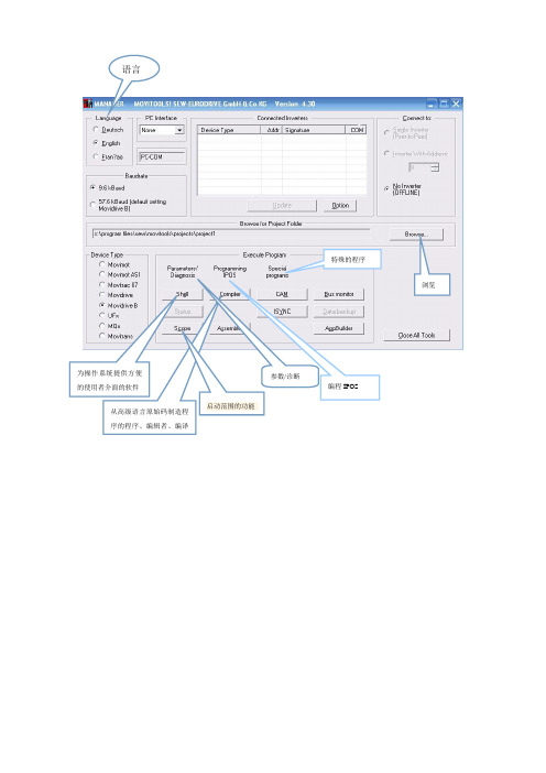
语言
为操作系统提供方便
的使用者介面的软件
从高级语言原始码制造程
序的程序、编辑者、编译
浏览启动范围的功能
参数/诊断
编程IPOS
特殊的程序
一、文件下子选项:
Save as...另存为
Print data...打印日期
二、启动子选项
Select technology function....选择技术功能的
1、STANDARD 标准的
2、CAM 凸轮
3、ISYNC
4、AUTO ASR
5、SBUS/TP
6、ROTARY KNIFE
this will overwrite unsaved parameters continue anyway 这将覆盖未保存的参数 maximum speed 1 最大速度
parameter menus 参数菜单
display values 显示值
setpoints/ramp generators 选点/斜坡生成器
controller parameters 控制器参数
motor parameters 电动机参数
reference signals 参考信号
monitoring functions 监视功能
terminal assignment 终端作业
没有初始化 默认值 值从文件
取消
脱机存储器是空的,你想怎样初始化 文件 启动 参数 显示、监控器 特别的 用户菜单
control functions 控制功能Unit functions 单位功能IPOS parameters IPOS 参数Applications 应用程序。
SEW变频器完成电机的初始化
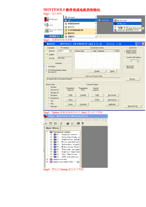
MOVITOOLS软件完成电机的初始化Step1:进入软件
Step2:设置软件相关参数
Step3:Update连接设备成功后点Shell进入以下界面
Step4:然后点Startup进入以下界面
Step5:进入设置
Step6:点Start——up Set 1进入参数设置组1
Step7:选择完全初始化后点下一步进入以下界面
Step8:选择矢量控制和伺服模式后点下一步进入以下界面
Step9:点下一步进入电机类型选择,选择相应类别即可(我们一般都是IEC标准电机)
Step10:设置电机相关参数,电机型号选择相应型号及其编码器TF传感器的型号即可
以上设置说明电机型号包含电机的生产标准,生产厂家,电机功率,电机携带编码器等
Step11:选择是否使用编码器
Step12:选择运行功能
Step13:选择运行模式
Step14:速度控制器相关设置
注意载荷的选择倍数和选择抱闸功能。
Step15:参数设置,绝大多数可以按照参考值来,因为这些数据都是标准电机的经验数据
斜坡先设置相对比较长的数据,舞台设备的速度斜坡大部分设置为2S左右,301、302是电机铭牌数据范围内的设置数据,不得超限
Step16:设置速度完成,下载参数和数据完成操作,显示出成功界面即可,如下图。
SEW软件使用方法资料

SEW软件使用方法资料SEW软件是一种用于工程领域的设计和仿真软件,主要用于机械系统、电气系统和液压系统的设计和分析。
本文将介绍SEW软件的使用方法,并包含以下主题:软件安装、新建项目、绘制图纸、添加元件、仿真分析和结果导出。
以下是详细的使用指南。
1.软件安装2.新建项目打开软件后,点击“文件”选项卡,在下拉菜单中选择“新建项目”。
在弹出的对话框中输入项目名称和保存路径,然后点击“确定”按钮创建新的项目。
3.绘制图纸4.添加元件SEW软件提供了大量的机械元件、电气元件和液压元件。
点击“元件库”按钮,在下拉菜单中选择所需的元件库。
可以通过在元件库中按关键词进行,然后将元件拖放到图纸上。
也可以使用元件库中的模板,直接将模板拖放到图纸上。
5.仿真分析在图纸上添加完所需的元件后,可以进行仿真分析。
首先,点击“仿真”选项卡,在下拉菜单中选择“配置仿真参数”。
然后,在弹出的对话框中设置所需的参数,比如工作条件、元件规格等。
接下来,点击“开始仿真”按钮开始仿真。
6.结果导出在仿真完成后,可以将结果导出为报告或图表。
首先,点击“结果”选项卡,在下拉菜单中选择“导出结果”。
然后,在弹出的对话框中选择要导出的结果类型,比如力学分析结果或电气分析结果。
最后,选择结果导出的格式和保存路径,点击“确定”按钮完成导出。
总结:SEW软件是一款功能强大的设计和仿真软件,可以用于机械系统、电气系统和液压系统的设计和分析。
本文介绍了SEW软件的使用方法,包括软件安装、新建项目、绘制图纸、添加元件、仿真分析和结果导出。
希望这些指南对你使用SEW软件有所帮助。
SEW内部IPOS设置和编程

举例
H10=H11+ H12; H10=H11 - H13; H10=H11 * H14; H10=H11 / H15;
LY 2_E
10/1998
IPOS-Compiler编辑器 运算指令说明 常用逻辑运算指令:
符号
“&& ” “||”
格式
(条件 1)&&(条件 2) (条件 1) ||(条件 2)
格式
说明
操作数左移 操作数右移 H3=H1<<2 H3=H1>>10
举例
例: H3=H1<<; 4 H1---0000,0000,1010,0101 H3---0000,1010,0101,0000
如果H1左移4位,右侧 由0添满
LY 2_E
10/1998
IPOS-Compiler编辑器 指令说明 常用比较指令:
H1 = 10; while ( H1 > 5 ) { H2 = H2 + 1; H1=H1-1; } while ( H1 < 20 ) { H1=H1+1; if ( H1 > 10 ) continue; H2 = H2 + 2; } 注:如果H1大于10,将不执行 H2=H2+2指令,跳到while 的末端。
说明: 便于用户编译和 解读程序。
多行注释 /* ... */
单行注释 // ...
单行注释//…
LY 2_E
10/1998
IPOS-Compiler编辑器 程序信息
选择下拉菜单
Display/Program Information
----显示程序信息
程序内存
创建日期
原文件目录
SEW变频器软件应用

拷贝至变频器中 点击“Start” 将参数下载至变频器中
SEW变频器
SEW变频器
具体参数的相关说明,详见:Sew_MDX60B 61B变频器操作手册
SEW变频器
刷新/取消按钮
当电脑搜索到所连变频器后,点击Compiler按钮,进入编程界面
SEW变频器
SEW变频器
3、故障列表分析
故障代 码 说明 响应 可能的故障原因 措施
• 启动 MOVITOOLS程序。
SEW变频器
语言选择英文 接口选择USB 选择点对点连接
选择通讯速度
软件版本:
MOVITOOLS_V4.90
选择变频器型号
SEW变频器
刷新/取消按钮
当电脑搜索到所连变频器后,点击Shell按钮,进入参数界面
SEW变频器
SEW变频器
从电脑文件中拷贝 参数保存的路径
F14
编码器
立即关闭
SEW变频器
故障代码的相关说明,详见:Sew_MDX60B 61B变频器操作手册
ቤተ መጻሕፍቲ ባይዱ
F08
n 速度监控
立即关闭
• 减小载荷 • 增加设置的减速时间 (P501 、P503)。 •转速控制器及电流控制器 ( 在无编码器 • 检查编码器接线,必要时以双对形式交 的 VFC 运行方式下 ) 由于机械过载或者 换 A/A 和B/B 电源或电机的相位故障在设定极限中工作。 • 检查编码器供电系统 • 编码器连接错误或旋转方向错误。 • 检查电流限制 • 力矩控制时 nmax 超限。 • 必要时延长斜坡 • 检查线路和电机 • 检查电源相位 • 编码器线或屏蔽线连接错误。 • 编码器线短路 / 断线 • 编码器损坏 检查编码器电缆和屏蔽线连接是否正确, 检查短路和断线。
SEW-零点设置方法

SEW-零点设置方法SEW伺服电机零点设置方法1.打开软件,连接变频器,打开shell,双击Application目录下的Extendedpositioning via bus (图1),打开调试软件界面(图2)。
2.首先使变频器X13接口DI00电源断开,把monitor模式切换成control模式,此时可以通过SEW软件手动模拟外部总线发送的控制字。
3.设置P01控制字为0A06(P01 control word 2)(图3),此时控制字为手动jog模式,正方向转动P02、03 不需要设置P04 设置速度(建议100以下)P05 为加速 Ramp(建议6000ms)P06 为减速Ramp (建议 6000ms)4.手动设置控制字和控制参数后,点击SendPA 按钮,此时所有手动设置参数被传送到变频器,伺服电机开始移动。
5.设置P02控制字的第二位(Enable/Rapid stop)或者第三位(Enable/Stop),然后点击SendPA按钮,可以停止电机转动。
(建议用Enable/Stop)6.紧急情况:可以按工位的急停按钮或者直接打开安全门,此时可以断开变频器的使能,直接使电机停止运转。
7.电机反转时,P02控制字设置为:0C06,其余操作相同。
8.手动移动伺服电机到零点位置,设置P02控制参数为1100,点击SendPA按钮,即可把当前位置设为零点参考位置(图4)。
9.零点设置完成后,把control模式更改为monitor模式。
具体可以参考SEW资料:2MOVIDRIVE MDX61B Extended Positioning via Bus Application.pdf 1.打开软件调试界面图12.更改操作模式从monitor到control。
3图23.jog 设置,手动运动4图34.地板伺服到达零点位置后,设置当前位置为零点方法5图45.设置完成后,把control 改为monitor control模式6954767。
SEW变频器软件应用

SEW变频器
语言选择英文 接口选择USB
选择点对点连接
0
选择通讯速度 选择变频器型号
SEW变频器
刷新/取消按钮 当电脑搜索到所连变频器后,点击Shell按钮,进入参数界面
SEW变频器
从电脑文件中拷贝
SEW变频器
参数保存的路径
拷贝至变频器中
点击“Start” 将参数下载至变频器中
SEW变频器
SEW变频器
具体参数的相关说明,详见:Sew_MDX60B 61B变频器操作手册
SEW变频器
刷新/取消按钮 当电脑搜索到所连变频器后,点击Compiler按钮,进入编程界面
SEW变频器
3、故障列表分析
SEW变频器
故障代 码
F08
F14
说明
响应
可能的故障原因
措施
n 速度监控 编码器
立即关闭 立即关闭
• 减小载荷
• 增加设置的减速时间 (P501 、P503)。
•转速控制器及电流控制器 ( 在无编码器 • 检查编码器接线,必要时以双对形式交
的 VFC 运行方式下 ) 由于机械过载或者 换 A/A 和B/B
电源或电机的相位故障在设定极限中工作。 • 检查编码器供电系统
• 编码器连接错误或旋转方向错误。
目录
硬件介绍 参数程序下载 故障列表分析
1、硬件介绍
SEW变频器
2、参数程序下载
SEW变频器
使用计算机进行调试时,必须使用 4.20 版以上的 MOVITOOLS程序。 • 端子 X13:1 (DIØØ “/CONTROL.INHIBIT”)必须获得 “0”信号! • 启动 MOVITOOLS程序。
• 检查电流限制
SEW软件使用方法资料
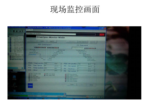
连接的变频器显示在此
打开软件,显示此 画面,先选择椭圆 框里的选项,最后 点Shell进入控制画面
连接的设备类型
关闭所有的工具
项目路径
设置零点的方法;1:拔掉使能线 2:切换到控制模式 3:电机走到想要的位置 4:设置PO1控制字的状态(Bit1;2;8; 11=1 其余全为0) 5:插上使能线,点传送(Send p0)这样就等于重新寻参了。也就是重新设定了零位。
3. 自动运行的过程: a.变频器使能, 设置硬件信号, Controller inhibit(DI00)=1
Enable(DI01)=1
设置控制字1“Enable / Rapid stop”=1. b.切换自动运行模式 c.设置给定位置和给定转速,如果设定 的位置和当前的实际位置不相同,位置 到达的状态”Position reached’=0 d.激活开始运行PO1:8“Start”=1,在整个 位置控制过程中保持 1. PO2和PO3定义目标位置 PO4定义转速设定值 PO5定义加速斜率 PO6定义减速斜率 2. PO1:15的电平定义在Startup中的2个位控斜率
c.激活参考运行PO1:8 “ Start ”=1
d.等待,到轴参考点P11:2”Axis referenced”=1
注:在设备第一次运行以及更换 编码器后,进行参考运行。
LY 2_E 10/1998
e.取消参考运行“ Start ”=0
自动模式
自动模式选择: PO1:11 = 1 PO1:12 = 1
LY 2_E 10/1998
e.等待,到目标位到达”Target position
reached”=1
d.取消位置运行”Start”=0
MOVIDRIVE A型固定为9.6KBaud MOVIDRIVE B型由S13开关决定 选择PC连接接口 SBUS、RS485地址
SEW——_ipos

TASC / Guoyu Fang / May 8, 2003 Slide 14
Driving the world
SEW 驱动控制产品
IPOS Complier 编程培训
例2
其次, 初始化变量中的值.
/*----------------------------------------------Initialisation -----------------------------------------------*/ ChangingVariable = 0;
Driving the world
SEW 驱动控制产品
IPOS Complier 编程培训
C-结构形式
if and if … else
if
此分支执行一个真表达式 (!= 0). //条件满足
此表达式可做成多个条件.
else
此分支执行一个非表达式 (= 0). //条件不满足 else 不必指定
最后编译并下载
Driving the world
TASC / Guoyu Fang / May 8, 2003 Slide 11
SEW 驱动控制产品
IPOS Complier 编程培训
系统功能
位处理功能:
_BitClear
相应变量的指定“位”置 0.
_BitMove
复制一个变量的个别位到另一个变量的指定位.
_WaitSystem
TASC / Guoyu Fang / May 8, 2003 Slide 13
SEW 驱动控制产品
IPOS Complier 编程培训
SEW内部IPOS设置和编程ppt课件

LY 2_E
10/1998
Task2程序部分
初始程序部分 激活Task2程序
主程序部分( Task1)
.
7
IPOS-Compiler编辑器 比较功能
点击 按钮----编辑器内程序和控制器内程序比较
控制器内程序和编辑器内程序不相同
控制器内程序和编辑器内程序相同
LY 2_E
10/1998
.
8
IPOS-Compiler编辑器 编译程序
二进制输出
端子 DO17
H482.X 10
含义
2 10
DO16 9 29
开关量输出DIO11A
DO15 DO14 DO13 DO12
8
7
6
5
28
27
26
25
DO11 4 24
DO10 3 23
主板开关量输出
DO02 DO01 DB00
2
1
0
22
21
20
注:
• H482开关量输入为只读。 • 例:H482.6=1代表了DO13为高电平的状态。 • 例:H482=19=24+21+20代表了DO11、DI01和DB00为高电平的状态,
H484(IPOS 控制字)
LY 2_E
10/1998
.
34
IPOS-Compiler编辑器
H509、H510和H511----位置值
变量
H509 H510 H511
名称
ACTPOS ABS ACTPOS EXT ACTPOS MOR
说明
绝对值编码器位置值 外部编码器位置值 电机编码器位置值
IPOS变量包括系统变量、全局变量和用户变量。
SEW_零点设置方法

SEW伺服电机零点设置方法1.打开软件,连接变频器,打开shell,双击Application目录下的Extendedpositioning via bus (图1),打开调试软件界面(图2)。
2.首先使变频器X13接口DI00电源断开,把monitor模式切换成control模式,此时可以通过SEW软件手动模拟外部总线发送的控制字。
3.设置P01控制字为0A06(P01 control word 2)(图3),此时控制字为手动jog模式,正方向转动P02、03 不需要设置P04 设置速度(建议100以下)P05 为加速 Ramp(建议6000ms)P06 为减速Ramp (建议 6000ms)4.手动设置控制字和控制参数后,点击SendPA 按钮,此时所有手动设置参数被传送到变频器,伺服电机开始移动。
5.设置P02控制字的第二位(Enable/Rapid stop)或者第三位(Enable/Stop),然后点击SendPA按钮,可以停止电机转动。
(建议用Enable/Stop)6.紧急情况:可以按工位的急停按钮或者直接打开安全门,此时可以断开变频器的使能,直接使电机停止运转。
7.电机反转时,P02控制字设置为:0C06,其余操作相同。
8.手动移动伺服电机到零点位置,设置P02控制参数为1100,点击SendPA按钮,即可把当前位置设为零点参考位置(图4)。
9.零点设置完成后,把control模式更改为monitor模式。
具体可以参考SEW资料:MOVIDRIVE MDX61B Extended Positioning via Bus Application.pdf1.打开软件调试界面图12.更改操作模式从monitor到control。
图23.jog 设置,手动运动图34.地板伺服到达零点位置后,设置当前位置为零点方法图45.设置完成后,把control 改为monitor control模式69547。
(完整版)SEW内部IPOS设置和编程

10/1998
程序占内存的 比例
程序扫描时间
IPOS-Compiler编辑器 编译并下载程序
点击
按钮----编译并下载程序
提示编译成功或不成功
LY 2_E
10/1998
IPOS-Compiler编辑器 插入指令行
点击 按钮----插入指令行(编辑器提供了标准的输入方式)
C-结构
系统功能
LY 2_E
10/1998
IPOS-Compiler编辑器
Compiler运算指令说明
LY 2_E
10/1998
IPOS-Compiler编辑器 运算指令说明
常用算术运算指令:
符号
格式
“+” H~= H~ + H~
“-” H~= H~ - H~
“×” H~= H~ * H~
“/” H~= H~ / H~
说明
IPOS-Compiler编辑器 指令说明
常用位与位逻辑运算指令:
符号
“&” “|” “^”
格式
(操作数1)&(操作数2) (操作数1)|(操作数2) (操作数1)^(操作数2)
说明
位和位与 位和位或 位和位异或
H3=H1&H2 H3=H1 | H2 H3=H1 ^H2
举例
H1---0000,0000,1111,1100 H2---0000,0000,0000,0101 H3---0000,0000,0000,0100
10/1998
IPOS-Compiler编辑器 运行和停止程序
点击 点击
按钮----运行程序 按钮----停止程序
TASK2状态显示 TASK1状态显示
LY 2_E
10/1998
SEW_位置模块
MOVIDRIVE®Extended Positioning via BusEdition07/2001Manual 1051 0516 / ENSEW-EURODRIVE3.4Limit switches, reference cams and machine zero (15)3.5Process data assignment (16)4Installation (18)4.1Software (18)4.2MDV/MDS60A with "type DIP11A absolute encoder interface" option (19)4.3MOVIDRIVE® MDV/MDS60A bus installation (20)4.4MOVIDRIVE® compact MCV/MCS41A (24)4.5Connecting the limit switches (25)5Startup (26)5.1General information (26)5.2Preliminary work (26)5.3Starting the "Extended positioning via bus" program (28)5.4Parameters (38)5.5Starting the drive (39)5.6Jog mode (40)5.7Referencing mode (41)5.8Automatic mode (42)6Operation and Service (43)6.1Timing diagrams (43)6.2Fault information (47)6.3Error messages (48)MOVIDRIVE®, Extended Positioning via Bus 34MOVIDRIVE ®, Extended Positioning via BusDocumentation •Read this manual carefully before you commence installation and startup of MOVIDRIVE ® drive inverters with this application module.•This manual assumes that the user has access to and is familiar with the MOVIDRIVE ® documentation, in particular the MOVIDRIVE ® system manual.•In this manual, cross references are marked with "→". For example, (→ Sec. X.X)means: Further information can be found in section X.X of this manual.•A requirement of fault-free operation and fulfillment of any rights to claim under guarantee is that the documentation is observed.Safety and warning instructionsAlways follow the safety and warning instructions contained in this publication!This manual does not replace the detailed operating instructions!Installation and startup only by trained personnel observing applicable accident prevention regulations and the MOVIDRIVE ® operating instructions!The "Extended positioning via bus" module is particularly suited to applications in whichit is necessary to move to any number of positions at different speeds and with differentaccelerating ramps. Positioning to an external encoder is necessary when there is anon-positive connection between the motor shaft and the load. In this case, either anincremental encoder or an absolute encoder can be used.The "Extended positioning via bus" application module is especially suitable for thefollowing sectors:•Materials handling technology–Trolleys–Hoists–Rail vehicles•Logistics–Storage and retrieval units for high-bay warehouses–Transverse carriages"Extended positioning via bus" offers the following advantages in theseapplications:•User-friendly user interface•Enter only those parameters required for "Extended positioning via bus" (ratios,speeds, diameters)•User-friendly application programs guide you through the process of settingparameters, so there is no need for complicated programming•Monitor mode for optimum diagnosis•No programming experience required•Long travel distances available (218× travel unit)•Incremental encoder or an absolute encoder can be used as external encoder.•No extended training period requiredMOVIDRIVE®, Extended Positioning via Bus 56MOVIDRIVE ®, Extended Positioning via Buscarriagepositioning via bus" application module. The following figure shows a transverse carriage in a high-bay warehouse. Goods to be moved in and out are transported between the shelf aisles and the distribution table. The transverse carriage has to cover long distances in this process. It also has to accelerate with different ramps and move at different speeds depending on the load.04823AXXFig. 1: Application example of a transverse carriageMOVIDRIVE ®, Extended Positioning via Bus7the MOVIDRIVE ® unit.1.With PC and MOVITOOLS:•Connect MOVIDRIVE ® to the PC via the serial port.•Start MOVITOOLS.•Select "Execute Program/Compiler".•In Compiler, select "Display/Program Information".•The "Program Information" window appears. The entries here tell you what application software is stored in MOVIDRIVE ®. The version number is also displayed.04920AENFig. 2: Starting the program information function04923AENFig. 3: "Program Information" windowProgram identificationing the DBG11A keypad, no PC required:•Select parameter P940 "Edit IPOS variables".•Set parameter P940 to ON. The keypad now displays "000V."•Press the ↑ key to increment the numbers and the → key to move the cursor tothe right. Set "128V."•The keypad now displays the content of variable H128 in decimal andhexadecimal notation.04924AXXFig. 4: Variable H128•The meaning of the decimal value in the first line is as follows:010*******Program version00001= Table positioning00002= Table positioning via fieldbus00003= Positioning via bus00004= Extended positioning via bus00005= Absolute positioning00006= Reserved00007= Reserved00008= Reserved00009= Reserved00010= Constant tension center winder00011= Reserved00012= Reserved...00100= Crane control...1= Positioning2= Winding technology3= Sequence control system4= Multi-axis application...8MOVIDRIVE®, Extended Positioning via BusPre-requisites3Project Planning3.1Pre-requisitesPC and software The "Extended positioning via bus" application module is implemented as an IPOS plus®program and forms part of the SEW MOVITOOLS software package. In order to useMOVITOOLS, you must have a PC with one of the following operating systems:Windows® 95, Windows® 98, Windows NT® version 4.0 or Windows® 2000. Inverters, motorsand encoders•InvertersTechnology version "Extended positioning via bus" can only be implemented on MOVIDRIVE® units in technology version (...-0T).Encoder feedback It is essential for "Extended positioning via bus" to have encoder feedback, i.e. it can only be implemented on MOVIDRIVE® MDV/MDS or MOVIDRIVE®compact MCV/MCS, not on MOVIDRIVE® MDF or MOVIDRIVE®compact MCF.MOVIDRIVE®MDV/MDS60A "Extended positioning via bus" uses 6 process data words. As a result, it is only possible to use the "PROFIBUS" and "INTERBUS with fiber optic cable" fieldbus types. You need the MOVIDRIVE® DFP21A, DFP11A or DFI21A option corresponding to the bus type you will be using.An external encoder is required for positioning in applications with a non-positive connection between the motor shaft and the load. The "absolute encoder interface type DIP11A" MOVIDRIVE® option is required in addition if an absolute encoder is used as the external encoder.MOVIDRIVE®compact MCV/ MCS41A"Extended positioning via bus" requires the MCV/MCS41A version of PROFIBUS-DP.•Motors–For operation on MOVIDRIVE® MDV or MOVIDRIVE®compact MCV: Asynchronous servomotors CT/CV (encoder installed as standard) or AC motors DR/DT/DV/D with encoder option.–For operation on MOVIDRIVE® MDS or MOVIDRIVE®compact MCS: Synchronous servomotors DS/DY, resolver installed as standard.Control viaPossible with MOVIDRIVE®compact MCV/MCS41A MDV/MDS60A PROFIBUS-DP Yes, without optionYes, with option DFP21A orDFP11A PROFIBUS-FMS,INTERBUS with fiber opticcableNoYes, with option DFP11A orDFI21AMOVIDRIVE®, Extended Positioning via Bus 910MOVIDRIVE ®, Extended Positioning via BusPre-requisites•External encodersMOVIDRIVE ® compact MCV/MCS41A cannot evaluate data from absolute encoders. Only incremental encoders with signals according to RS-422 (5 V TTL)can be used as external encoders in applications with non-positive connection between motor shaft and load.–Interlocking (= zero slip) connection between motor shaft and load: No external encoder required. If you also want to use an external encoder for positioning when there is an interlocking connection, you have to proceed in exactly the same way as with a non-positive connection.–Non-positive (= with slip) connection between motor shaft and load: An external encoder required as well as the motor encoder/resolver.–Incremental encoder as external encoder → Connection to basic unit X14.–Only with MOVIDRIVE ® MDV/MDS60A: Absolute encoder as external encoder → Connection on DIP11A option X62.The approved absolute encoders are listed in the DIP selection list (→ MOVIDRIVE ®MD_60A system manual, description of parameter P950).•MOVIDRIVE ® MDV/MDS60A combinations:•MOVIDRIVE ® compact MCV/MCS41A combinations:ConnectionMotor shaft/load Interlocking, no externalencoder requiredNon-positive, external encoder required Type of external encoder -Incremental encoderAbsolute encoderReference travel YesYesNoBus type→ Required option PROFIBUS DP (12 Mbaud) → DFP21APROFIBUS FMS/DP → DFP11A INTERBUS LWL → DFI21AOther MOVIDRIVE ® option requiredNoNoAbsolute encoderinterface Type DIP11A ConnectionMotor shaft/load Interlocking, no externalencoder requiredNon-positive, external encoderrequiredType of external encoder -Incremental encoderReference travelYesYesFunctional description3.2Functional descriptionFunctional characteristicsThe "Extended positioning via bus" application offers the following functional characteristics:•Any number of target positions can be specified via the fieldbus.•Long travel distance available. The maximum possible travel distance depends on the set travel unit, for example:•The speed and ramps must be set using the bus for positioning.•Software limit switches can be defined and evaluated.•Incremental encoders or absolute encoders can be evaluated as external encoders.•Simple connection to the machine control (PLC).Operating modes The functions are implemented with three operating modes:•Jog mode–The drive is moved clockwise or counterclockwise using bits 9 or 10 in control word 2 (PO1).–The speed and the ramps are variable and specified via fieldbus.•Referencing mode–Reference travel is started with bit 8 in control word 2 (PO1). Reference travel establishes the reference point (machine zero ) for absolute positioning operations.–Reference travel can be performed even if an absolute encoder is used as the external encoder.•Automatic mode–Positioning is started in automatic mode with bit 8 in control word 2 (PO1).–The target position is specified with process output data words PO2 and PO3.–The actual position is signaled back cyclically in user travel units with process input data words PI2 and PI3.–The set speed is specified with process output data word PO4.–The actual speed is signaled back cyclically with process input data word PI4.–Accelerating and deceleration ramps are specified with process output data words PO5 and PO6.–The active current and unit utilization are signaled back cyclically with process input data words PI5 and PI6.–Confirmation of the target position to which movement has taken place via virtual binary output "target position reached."Travel unit Maximum possible travel distance1/10 mm 26.2144 m mm262.144 mFunctional description04825AXXFig. 5: Data exchange via process dataPA= Process output data PE= Process input dataPA1= Control word 2PE1= Status wordPA2= Target position high PE2= Actual position highPA3= Target position low PE3= Actual position lowPA4= Set speed PE4= Actual speedPA5= Accelerating ramp PE5= Active currentPA6= Deceleration ramp PE6= Unit utilizationLimits The set speed for positioning movement is specified using process output data word PO4. For safety reasons, you can also limit the maximum permitted speed for automaticmode and jog mode.Note that P302 "Maximal speed 1" must be at least 10 % higher than the set limits forautomatic mode and jog mode.In addition, the numerator factor for scaling the travel is restricted to the value 8192.Scaling of the drive3.3Scaling of the driveThe control needs to know the number of encoder pulses (increments) per travel unit so it can calculate the travel information and position the drive correctly. Furthermore, you can use the scaling function to set the user travel unit suitable for your application.Drives without an external encoder (interlocking connection)In drives without an external encoder, you can have scaling performed automatically by the "Extended positioning via bus" startup procedure. To do this, you have to enter the following data:•Diameter of the drive wheel or the spindle pitch •Gear unit ratio (i gear unit, speed reduction)•Additional gear ratio (i additional gear, speed reduction)The startup procedure then calculates the following scaling factors:1.Pulses/distance scaling factor [inc/mm] according to the formula:Pulses = 4096 × i gear unit × i additional gear Distance = π × d drive wheel or s spindle pitch2.Speed scaling factor (numerator value in rpm and denominator value in mm/s)You can also enter m/min or rpm as the unit for the denominator value.It is also possible to enter the pulses/distance and the scaling factor of the speed directly. If you enter a unit other than millimeter [mm] as the travel unit, this selected unit will also be used for position of the software limit switches, the reference offset and the bus positions.Drive with an external encoder (non-positive connection)In this case, you must have activated and scaled the external encoder before starting up "Extended positioning via bus." Make the following settings in MOVITOOLS/SHELL in order to do this:•Set P941 "Source actual position," EXTERN.ENC (X14) with incremental encoder or ABSOL.ENC. (DIP). You can also make this setting during the startup of "Extended positioning via bus."•Set P942 – P944 encoder factor numerator and denominator as well as encoder scaling ext. encoder. You have to make these settings in MOVITOOLS/SHELL before starting up "Extended positioning via bus."Calculation of the scaling is now blocked during startup of "Extended positioning via bus."For more information about scaling of an external encoder, please refer to the "IPOS plus® Positioning and Sequence Control System" manual.02770AENFig. 6: Setting the actual position sourceScaling of the driveActivating the absolute encoderOnly with MOVIDRIVE ® MDV/MDS60A: If you are using an absolute encoder as the external encoder, you must start-up the absolute encoder before starting "Extended positioning via bus." Proceed as follows to do this:•Start-up the inverter with "MOVITOOLS/Shell".•Select "Startup / Startup for / DIP".•Perform the startup procedure for the DIP absolute encoder.Please refer to the "Positioning with Absolute Encoder and Absolute Encoder Interface DIP11A" manual for more information about starting up of absolute encoders.04941AENFig. 7: Inverter startup04992AENFig. 8: Absolute encoder startupLimit switches, reference cams and machine zero3.4Limit switches, reference cams and machine zeroSoftware limit switchesSoftware limit switches perform an additional safety function by defining the limits of the travel range. Note the following points:•The software limit switches must be located within the travel range of the hardware limit switches.•Travel commands are not performed if their target positions lie beyond the software limit switches.•Error message F78 "IPOS SW limit switch" is generated if a target position beyond the software limit switch is specified using the fieldbus. This error message must be acknowledged with a reset. The drive loses its reference position when you do this.Reference cam •Make sure there is no overlap when defining the reference position (position of the reference cam) and the software limit switches. Error message F78 "IPOS SW limit switch" is generated in the event of an overlap during referencing.Machine zero •You must enter a reference offset during startup of "Extended positioning via bus" if you do not want the machine zero (= reference point for bus positioning) to be located on the reference point.•The following formula applies: Machine zero = Reference position + Reference offsetIn this way, you can alter the machine zero without having to move the reference cam.The position value is not lost by a reset if you are using an absolute encoder for positioning. Just enter a new target position in between the software limit switches and then perform the reset. Otherwise, error F78 is generated again.Process data assignment3.5Process data assignmentThe machine control (PLC) sends 6 process output data words (PA1 – PA6) to the inverter and receives 6 process input data words (PE1 – PE6) from the inverter.Process output dataThe assignment of the process output data words is as follows:•PA1: Control word 2•PA2 + PA3: Target position•PA4: Set speed04825AXXFig. 9: Data exchange via process dataPA = Process output data PE = Process input data PA1= Control word 2PE1= Status word (IPOS PI data)PA2= Target position high PE2= Actual position high (IPOS PI data)PA3= Target position low PE3= Actual position low (IPOS PI data)PA4= Set speed (IPOS PO data)PE4= Actual speed (IPOS PI data)PA5= Accelerating ramp (IPOS PO data)PE5= Active current (IPOS PI data)PA5= Deceleration ramp (IPOS PO data)PE6= Unit utilization (IPOS PI data)151413121110987654321Reserved Controller inhibit/enableReserved Enable/rapid stop Reserved Enable/stop Mode selecthigh /Hold control Mode select lowRamp switchover Jog -Parameter set switchover Jog +Error reset StartReservedPA2 Target position highPA3 Target position low151413121110987654321151413121110987654321Target position [user-defined travel unit]PA4 Set speed151413121110987654321Set speed [rpm]Process data assignment •PA5 + PA6: Acceleration ramp and deceleration rampProcess input dataThe assignment of the process input data words is as follows:•PE1: Status word•PI2 + PI3: Actual position•PE4: Actual speed•PE5: Active current•PE6: Unit utilizationPA5 Acceleration ramp PA6 Deceleration ramp15141312111098765432101514131211109876543210Ramps [s]1514131211109876543210Inverter status/error codeMotor turning (n ≠ 0)Inverter readyIPOS reference (= drive referenced)Target position reachedBrake releasedFault/warningCW limit switchCCW limit switchPE2 Actual position high PE3 Actual position low 15141312111098765432101514131211109876543210Actual position [user-defined travel unit]PE4 Actual speed1514131211109876543210Actual speed [rpm]PE5 Active current151413121110987654321010Active current [% rated unit current]PE6 Unit utilization151413121110987654321010Unit utilization [% I × t]4.1SoftwareMOVITOOLS The "Extended positioning via bus" application module is part of the SEW MOVITOOLS software package (version 2.60 and higher). Proceed as follows to install MOVITOOLSon your computer:•Insert the MOVITOOLS CD into the CD ROM drive of your PC.•Select "Start/Run...".•Type "{Drive letter of your CD drive}:setup" and press the Enter key.•The MOVITOOLS setup menu appears. Follow the instructions of the installation wizard.You can now use Program Manager to start MOVITOOLS. If a MOVIDRIVE® unit isconnected to your PC, select the correct port (PC COM port) and set point-to-pointconnection. Select <Update> to display the inverter in the "Connected Units" window.Technology version (from version 2.70)The "Extended positioning via bus" application module can be used with MOVIDRIVE®MDV/MDS60A units in the technology version (-0T). The application modules cannot be used with units in the standard version (-00).04431BEN Fig. 10: MOVITOOLS window04826AENFig. 11: Wiring diagram for basic unit with DIP11A optionOverview For bus installation, please note the information in the relevant fieldbus manuals enclosed with the fieldbus interfaces.04827AXXFig. 12: Bus types(DFP21A)can be ordered from SEW. The documentation package contains the GSD files and type files for MOVIDRIVE® in order to help with project planning and to facilitate startup. Technical dataPin assignment04434AXXFig. 13: Assignment of 9-pin sub D plug to EN 50170 V2(1)9-pin sub D plug(2)Twist the signal wires together!(3)Conductive connection is necessary between the plug housing and the shield!(DFP11A)can be ordered from SEW. This documentation package contains the GSD files and type files for MOVIDRIVE ® in order to help with project planning and to facilitate startup.Technical dataPin assignment04434AXXFig. 14: Assignment of 9-pin sub D plug to EN 50170 V2(1)9-pin sub D plug(2)Twist the signal wires together!(3)Conductive connection is necessary between the plug housing and the shield!fiber optic cablepackage can be ordered from SEW.(DFI21A)Technical data ArrayConnectionassignmentPosition Signal Direction FO core color3FO remote IN Receive data Orange (OG)4Incoming remote bus Send data Black (BK)5FO remote OUT Receive data Black (BK)6Outgoing remote bus Send data Orange (OG)MOVIDRIVE® compact MCV/MCS41A 4.4MOVIDRIVE® compact MCV/MCS41APROFIBUS-DP pin assignment Refer to the instructions in the MOVIDRIVE®compact MC_41A operating instructions.04940AENFig. 15: Wiring diagram for MOVIDRIVE® compact MCV/MCS41AThe cams of the limit switches must cover the travel range up to the stop.Use limit switches with NC contacts (low-active) only!04437AXXFig. 17: Connecting the limit switchesCW= Clockwise drive inverterX= TravelLS CW= Limit switch clockwiseLS CCW= Limit switch counterclockwiseMake sure the limit switch assignment is correct. This means clockwise movement (CW) should be towards the clockwise limit switch (LS CW) and counterclockwise movement(CCW) should be towards the counterclockwise limit switch (LS CCW).5.1General informationCorrect project planning and installation are the pre-requisites for successful startup.Refer to the MOVIDRIVE® MD_60A and MOVIDRIVE®compact system manuals fordetailed project planning instructions. These system manuals form part of theMOVIDRIVE® MD_60A and MOVIDRIVE®compact documentation packages whichyou can order from SEW.Check the installation, including the encoder connection, by following the installationinstructions in the MOVIDRIVE® operating instructions and in this manual (→Sec.Installation).If you are using an absolute encoder, please also follow the installation and startupinstructions for the absolute encoder in the "Positioning with Absolute Encoder andAbsolute Encoder Interface DIP11A" manual available from SEW.5.2Preliminary workPerform the following steps before startup:•Connect the inverter to the PC using the serial port (RS-232, USS21A on PC-COM).•Install the SEW MOVITOOLS software (version 2.60 or higher).•Start-up the inverter with "MOVITOOLS/Shell."•Set the following operating modes:04941AENFig. 18: Inverter start-upInvertersMotor typeDR/DT/DV/D CT/CV DS/DYMOVIDRIVE® MDV60A orMOVIDRIVE®compact MCV41AVFC-n-CTRL& IPOS CFC & IPOS-MOVIDRIVE® MDS60A or MOVIDRIVE®compact MCS41A --SERVO&IPOS–In MOVITOOLS/SHELL, set P942...P944 encoder factor numerator, encoder factor denominator and encoder scaling ext. encoder. Refer to the "IPOS plus®Positioning and Sequence Control System" manual for a detailed description of parameters P942 (944)•Operating with an absolute encoder on DIP: X62 as external encoder:–Select "Startup / Startup for / DIP absolute encoder."–Perform the startup procedure for the DIP absolute encoder.•"0" signal at terminal X13:1 (DIØØ, /Controller inhibit).04992AENFig. 19: Absolute encoder startupGeneralinformation•Start "MOVITOOLS/Shell."•Select "Startup/Extended positioning via bus."Initial startupThe startup window appears immediately when "Extended positioning via bus" is started for the first time.04829AENFig. 20: Starting the "Extended positioning via bus" programparameters•Set the correct fieldbus type.•Set the required bus parameters.•Press "Forward >>" to open the next startup window.04830AENFig. 21: Setting the fieldbus parameters•Set the "Source actual position." The following settings are possible:–"MOTOR ENC. (X15)" for operation without an external encoder.–"EXTERN.ENC (X14)" with an incremental encoder as the external encoder.–"ABSOL.ENC. (DIP)" with the DIP11A option and an absolute encoder as the external encoder.•Only if "Source actual position = MOTOR ENC. (X15)": Perform "Calculation of the scaling." Enter the following values to do this:–Enter the value for "Diameter of driving wheel" or "Spindle slope" in the unit millimeter [mm] or 1/10 millimeter [1/10 mm].–Enter the ratio (i) values for the gear unit and additional gear.–Select the "Unit for speed."–Press <Calculation> to calculate the scaling factor. The "Increments/distance"values are entered in [inc/mm].You can also calculate the "Scaling factor for distance" yourself and enter the value directly. In this case, you can enter a unit other than millimeters for the distance.04832AENFig. 22: Setting the scaling•"Scaling factor for distance"The "Scaling factor for distance" is calculated and entered automatically if you have the scaling calculated by the program. The numerator factor is limited to max. 8192 inc in this case. You have to calculate and enter the scaling factor yourself if you do not have it calculated by the program, for example if you are using an external encoder.Note that the numerator factor is not to exceed 8192 increments in this case.Example for calculating the "Scaling factor for distance:"Positioning to an absolute encoder type WCS2 (Stahl).Physical encoder resolution = 1.25 increments/mmEncoder scaling P955 = 8Encoder resolution with encoder scaling = 10 increments/millimeter [inc/mm]Set "Increments/Distance = 10/1 [inc/mm]."•"Scaling factor for speed"The "Scaling factor for speed" is entered automatically if you have the scaling calculated by the program. The unit for the denominator is the same as set previously in "Unit for speed." You have to calculate and enter the scaling factor yourself if you do not have it calculated by the program, for example if you are using an external encoder.Example for calculating the "Scaling factor for speed:"Positioning to an absolute encoder type WCS2 (Stahl).Numerator = i gear unit× i additional gear× Conversion factor for speedNumerator = 2 × 1 × 60 s/min = 120 s/minDenominator = Circumference = pi × d = 3.14159 × 50 mm = 157.08 mmSet the following values:Numerator = 12000Denominator = 15708Note that the numerator and the denominator value are not to exceed 32,767.。
sew调试步骤自己总结

sew调试步骤自己总结s e w调试步骤自己总结 Document serial number【NL89WT-NY98YT-NC8CB-NNUUT-NUT108】1.变频器调试步骤:(所用软件为M O V I T O O L S)设置网关DP地址,然后短接所有变频器的DI01与24VIO端子,然后变频器与PC通信,点扫描,扫描出设备后下载变频器启动信息,即parameter1(设置控制方式为VF,根据实际情况设置电机型号),然后修改参数,如P100设为SBUS/Fixed,P101设为SBUS,P600等设为NO FUNCTION,P881设为1,其他变频器也是这样,只是修改一下P881(系统总线的地址)的数值。
然后网关与PC 通信,扫描出与网关通信的所有变频器,然后知道变频器与PLC通信的所用的外设地址,最后把最后一个变频器的S1和S2接通,其余变频器的S1与S2断开,最后在通电状态下把AS 接通(切记是在所有变频器的S1与S2设置正确的前提下)。
伺服调试步骤:(所用软件为MT_Manger)设置伺服DP地址,然后断开DIOO与24VIO,接通DI01与24VIO,同时接通7与9端子,然后软件与伺服通信,通信波特率为,型号为MOVITRAC B,点对点通信方式,下载伺服启动信息,设置转动惯量为100,电机温度过高时立即停止然后把启动信息下载到伺服(必须在禁止模式下)。
然后点通过扩展总线控制,选择通信方式为DP,然后电子齿轮比用默认值,不能点击Caculate,即电子齿轮比全部采用默认值,直接点击NEXT,然后设置软限位,然后下载到伺服(必须在禁止模式下)。
然后进入监控模式,伺服启动必须先设置手动启动,此时状态字Motor turning为1,此时若IPOS reference位为0,必须进行寻参模式,才能启动自动模式,寻参模式启动方法如下:寻参:1.设置P902的参数,确定寻参类型为0,然后在控制模式下通过PC发控制字以及0转速给伺服,即启动寻参,寻参原位信号通过端子DI03(端子功能为Reference Travel)传入,为1时减速,脱离时停止,同时将当前位置清零,此时IPOS reference位为1。
- 1、下载文档前请自行甄别文档内容的完整性,平台不提供额外的编辑、内容补充、找答案等附加服务。
- 2、"仅部分预览"的文档,不可在线预览部分如存在完整性等问题,可反馈申请退款(可完整预览的文档不适用该条件!)。
- 3、如文档侵犯您的权益,请联系客服反馈,我们会尽快为您处理(人工客服工作时间:9:00-18:30)。
10 2
10
9 2
9
8 2
8
5
6
4
5
3
4
2
3
1
2
0
1
2
2
2
2
2
2
2
2
0
注:
•开关量输入为只读。 • 例:H483.6=1代表了DI10为高电平的状态。 • 例:H483=19=24+21+20代表了DI04、DI01和DI00为高电平的状态,
其余开关量输入为低电平。
LY 2_E
10/1998
IPOS-Compiler编辑器
如果H1左移4位,右侧 由0添满
LY 2_E
10/1998
IPOS-Compiler编辑器 指令说明 常用比较指令:
符号
“>” “>=” “<” “<=” “==” “!=”
格式
操作数1 >操作数2 操作数1 >=操作数3 操作数1 <=操作数4 操作数1 <=操作数5 操作数1 ==操作数6 操作数1 !=操作数7
LY 2_E 10/1998
例3:
H1 = 0; while ( 1 ) { ++H1; if ( H1 == 20 ) break; if ( H1 > 10 ) continue; H2 = H2 + 2; } 注:如果H1等于20,将退出while 指令;如果H1大于10,跳到 while的末端。
1
DB00 0 2
0
注:
• H482开关量输入为只读。 • 例:H482.6=1代表了DO13为高电平的状态。 • 例:H482=19=24+21+20代表了DO11、DI01和DB00为高电平的状态,
其余开关量输出为低电平。
LY 2_E
10/1998
IPOS-Compiler编辑器
H481(OUTPUT LVL)---开关量输出---只写
名称
ACTPOS ABS ACTPOS EXT ACTPOS MOR
说明
绝对值编码器位置值 外部编码器位置值 电机编码器位置值
接口
X62 X14 X15
LY 2_E
10/1998
IPOS-Compiler编辑器
程序块(无 else 分支)
if ( H1 > 3 ) { H2 = 10; H3 = 11; }
程序块(有 else 分支)
if ( H1 > 3 ) H2 = 9; else { H2 = 10; H3 = 11; }
LY 2_E
10/1998
IPOS-Compiler编辑器 指令说明--- while
说明
大于 大于等于 小于 小于等于 操作数左移 不等于
举例
例:
if ((H1==3)&&(H2>=5)) { H100=H1+H2 ;
如果H1等于3,并且H2大于等于5时, 执行H100=H1+H2;
}
LY 2_E 10/1998
IPOS-Compiler编辑器
Compiler结构指令说明
LY 2_E
H482(OUTPUT LVL)---开关量输出
二进制输出 端子 H482.X 含义 DO17 10 2
10
开关量输出DIO11A DO16 9 2
9
主板开关量输出 DO12 5 2
5
DO15 8 2
8
DO14 7 2
7
DO13 6 2
6
DO11 4 2
4
DO10 3 2
3
DO02 2 2
2
DO01 1 2
举例
H10=H11+ H12; H10=H11 - H13; H10=H11 * H14; H10=H11 / H15;
LY 2_E
10/1998
IPOS-Compiler编辑器 运算指令说明 常用逻辑运算指令:
符号
“&&” “||”
格式
(条件1)&&(条件2) (条件1)||(条件2)
说明
与 或
IPOS-Compiler编辑器 指令说明 常用位与位逻辑运算指令:
符号
“&” “|” “^”
格式
(操作数1)&(操作数2) (操作数1)|(操作数2) (操作数1)^(操作数2)
说明
位和位与 位和位或 位和位异或 H3=H1&H2 H3=H1 | H2 H3=H1 ^H2
举例
H1---0000,0000,1111,1100 H2---0000,0000,0000,0101 H3---0000,0000,0000,0100
说明: 便于用户编译和 解读程序。
多行注释 /* ... */
单行注释 // ...
单行注释//…
LY 2_E
10/1998
IPOS-Compiler编辑器 程序信息
选择下拉菜单
Display/Program Information
----显示E
10/1998
二进制输出 端子 H481.X 含义 DO02 2 22
主板开关量输出 DO01 1 21 DB00 0 20
注:
• H482开关量输入为只写。 • 例:H481.2=1代表了设置DO02为高电平。 • 例:H481=6=22+21代表了设置DO02、DO01为高电平。
LY 2_E
10/1998
IPOS-Compiler编辑器
IPOS-Compiler编辑器
Compiler运算指令说明
LY 2_E
10/1998
IPOS-Compiler编辑器 运算指令说明 常用算术运算指令:
符号
“+” “-” “×” “/” H~= H~ + H~ H~= H~ - H~ H~= H~ * H~ H~= H~ / H~
格式
说明
加 减 乘 除
H480(OUTPUT LVL)---开关量输出---只写
二进制输出 端子 H480.X 含义 DO17 7 2
7
开关量输出DIO11A DO16 6 2
6
DO15 5 2
5
DO14 4 2
4
DO13 3 2
3
DO12 2 2
2
DO11 1 2
1
DO10 0 2
0
注:
• H480开关量输入为只写。 • 例:H480.2=1代表了设置DO12为高电平。 • 例:H481=6=22+21代表了设置DO12、DO11为高电平。
当条件都不满足时,执行程序n。
例:
switch ( H1 ) { case 1: ++H2; break; case 2: ++H3; break; default: ++H4; break; }
注:如果H1等于1,H2加1; 如果H1等于2,H2加1; 如果H1等于3,H3加1; 如果H1不等于1、2或3,H4加1;
IPOS变量包括系统变量、全局变量和用户变量。
• 系统变量为有固定含义变量(H453---H511)。 • 全局变量为特殊应用模块中指定的变量。 • 用户变量为用户程序中可任意调用的变量。
LY 2_E
10/1998
IPOS-Compiler编辑器 变量窗口
选择下拉菜单
Display/Variable watch/Edit window
举例
例: if ((H1==3)&&(H2==5)) { H100=H1+H2 ; } 例: if ((H1>10) || (H2<5)) { H100=H1+H2 ; }
LY 2_E 10/1998
如果H1等于3,并且H2等于5时 执行H100=H1+H2; 如果H1大于10,或者H2小于5时 执行H100=H1+H2;
LY 2_E
10/1998
IPOS-Compiler编辑器
常用的系统变量说明
LY 2_E
10/1998
IPOS-Compiler编辑器
H483(INPUT LVL)---开关量输入
二进制输入
端子定义 H483.x 含义 13 2
13
DI011A二进制输入
12 2
12
主板二进制输入
7 6
7
DI17 DI16 DI15 DI14 DI13 DI12 DI11 DI10 DI05 DI04 DI03 DI02 DI01 DI00 11 2
工具栏和菜单栏
LY 2_E
10/1998
IPOS-Compiler编辑器 创建新项目 点击
初始部分
按钮----创建新项目
对话框用于定义IPOS 程序的基本结构。
任务2
中断响应
LY 2_E
10/1998
IPOS-Compiler编辑器
程序编辑器说明
Task2程序部分
初始程序部分
激活Task2程序
主程序部分( Task1)
IPOS-Compiler编辑器
编辑器软件说明
LY 2_E
10/1998
IPOS-Compiler编辑器 激活编辑器
开始IPOSCompiler编辑器
LY 2_E
10/1998
IPOS-Compiler编辑器 编辑器程序窗口说明
菜单栏 工具栏
目录栏
程序窗口
状态栏
LY 2_E
10/1998
IPOS-Compiler编辑器
或运算
H1---0000,0000,1111,1100 H2---0000,0000,0000,0101 H3---0000,0000,1111,1101
