API_SPEC_5L_CHS
华三路由器软件升级指南

内存错误代码大全

系统内存蓝屏的错误代码大全系统内存蓝屏的错误代码大全0 0x00000000 作業完成。
1 0x00000001 不正确的函數。
2 0x00000002 系統找不到指定的檔案。
3 0x00000003 系統找不到指定的路徑。
4 0x00000004 系統無法開啓檔案。
5 0x00000005 拒絕存取。
6 0x00000006 無效的代碼。
7 0x00000007 儲存體控制區塊已毀。
8 0x00000008 儲存體空間不足,無法處理這個指令。
9 0x00000009 儲存體控制區塊地址無效。
10 0x0000000A 環境不正确。
11 0x0000000B 嘗試加載一個格式錯誤的程序。
12 0x0000000C 存取碼錯誤。
13 0x0000000D 資料錯誤。
14 0x0000000E 儲存體空間不夠,無法完成這項作業。
15 0x0000000F 系統找不到指定的磁盤驅動器。
16 0x00000010 無法移除目錄。
16 0x00000010 無法移除目錄。
17 0x00000011 系統無法将檔案移到其它的磁盤驅動器。
18 0x00000012 沒有任何檔案。
19 0x00000013 儲存媒體爲寫保護狀态。
20 0x00000014 系統找不到指定的裝置。
21 0x00000015 裝置尚未就緒。
22 0x00000016 裝置無法識别指令。
23 0x00000017 資料錯誤 (cyclic redundancy check)24 0x00000018 程序發出一個長度錯誤的指令。
25 0x00000019 磁盤驅動器在磁盤找不到持定的扇區或磁道。
26 0x0000001A 指定的磁盤或磁盤無法存取。
27 0x0000001B 磁盤驅動器找不到要求的扇區。
28 0x0000001C 打印機沒有紙。
29 0x0000001D 系統無法将資料寫入指定的磁盤驅動器。
30 0x0000001E 系統無法讀取指定的裝置。
API 5B课件

牙型特点 (1)油管及圆螺纹套管 螺纹为圆螺纹(齿顶、齿底为圆弧状);锥度为1:16; 牙型角为60°,牙侧角为30°;螺距为3.175和2.54(8牙 和10牙/吋)牙型高度:1.810(8牙/吋)、1.412(10牙/吋)。 注:玻璃纤维油管采用外加厚长圆螺纹油管型式。 (2)偏梯形套管 13 3/8″以下锥度为1:16,16″以上锥度为1:12,螺距 为5.08(5牙/寸);牙型高为1.575;牙侧角为3°和13°,牙 型角为13°。
9、全顶螺纹是齿顶指具有完全形状的螺纹,当然全底螺纹是齿 底具有完全形状的螺纹。 10、有效螺纹对油套管指外螺纹根部牙底消失锥角起始点以前 的螺纹,L2即为有效螺纹长度;
2016 API 5B培训讲义(摩尔)
11、手紧紧密距A是两个具有相同规格的部件没有产生机械过 盈时的名义上紧位置。
12、合格的校对量规的配对紧密距值S是校对塞规上消失点平面 与校对环规端面的距离。 13、合格的校对环规用以确定工作塞规的互换紧密距值S1, 14、合格的校对量规的配对紧密距P是塞规端面与环规小端的距 离之差。 15、合格的校对塞规用确定工作环规的互换紧密距值P1.
2016
API 5B培训讲义(摩尔)
受内外压差(一般为几百个大气压)的长期作用而不泄漏 。螺纹连接强度和密封性能是油井管极为重要的两个技术 指标。 螺纹检验的目的就是要把螺纹质量不合格的管子检查出来 ,防止不合格管下井,最大限度避免或减少油井管失效事故 的发生。油井管螺纹失效形式主要有:丝扣断裂、粘扣、 滑脱、泄漏等。处理事故少则几十万,多则几百万,甚至 整口井报废,造成重大的经济损失。
2016 API 5B培训讲义(摩尔)
②内螺纹最后一牙完整螺纹的位置,是在距离接箍的自然 中心或整体连接油管内螺纹小端J+lp处。 注:g值列于表18、表19、表20、表21、表22和表23。对 于圆螺纹,套管的“g”值选定为0.625 in(15.88 mm) ,油管的为0.500 in(12.7 mm)。
FCC规范第15部分类A数字设备说明书

O5MDP1Revision History1.Introduction (5)1.1. Overview (5)1.2. Specification (6)1.3. Applications of O5MDP1 (7)2.Product Description (8)2.1. Contents (8)2.2. Product Preview (8)2.3. Physical description (9)2.3.1. External View (9)2.3.2. Dimension (9)2.3.3. External Connector (10)2.3.4. Factory Default Switch (10)2.4. Functional Description (11)3.On Site Installation (13)4.Getting Started (14)4.1. PC Requirement (14)4.2. Quick Installation Guide (14)4.2.1. Connect PC and O5MDP1 to network. (14)4.2.2. Install Speco-NVR and set IP parameters on O5MDP1 (15)4.2.3. Remote video connection to O5MDP1 (17)4.2.4. Additional settings through connection to the Admin Page (19)4.2.5. Panoramic viewing through Speco-NVR (20)5.Trouble Shooting (21)5.1. No power is applied (21)5.2. Cannot connect to the Video (22)5.3. Windows Vista or Windows 7 (23)5.4. Technical Assistance (26)Appendix A – Important Notice in Exchanging SD Card (Micro SD) (27)1.1. OverviewThe O5MDP1 is panoramic IP camera offering panoramic view of 360︒ or 180︒ for covering entire surveillance area with a single IP camera. 5 Mega Pixel image from Panomorph camera module can replace up to 4 PTZ cameras and 5 fixed cameras. It enables real time transmission of synchronized video of up to 2,592x1,944(10fps) video and audio data. Remote clients can connect to O5MDP1 for the real time video/audio data through various client solutions running on PC or smart device. Real time 2-way communication is available through bidirectional audio communication feature.Designed to be a stand-alone streaming audio & video transmission device, O5MDP1 can be applied to various application area such as video security, remote video monitoring, distance education, video conference or internet broadcasting system.Vandal proof and weather proof housingwillextendtheapplication area to harsh environment of wide temperature range. Embedded PoE (Power over Ethernet, IEEE 802.3af) will enable the owner to reduce the total cost of ownership by reducing on-site wiring works for the installation.Original VideoPTZ modePan/Tilt/Zoom ControlQuad modeEach sub-screen with independent Pan/Tilt/Zoom replaces 4 independent PTZ cameras.Perimeter mode2 x180︒views with panning control for ceiling mount. One 180︒ views for wallmount. Replaces two 180︒ cameras..Up to 5 crop windows of 320 x 240. Replaces up to 5 fixed cameras.1.3. Applications of O5MDP1•Security surveillance (buildings, stores, manufacturing facilities, parking lots, banks, government facilities, military, etc.)•Remote monitoring (hospitals, kindergartens, traffic, public areas, etc.)•eleconference (Bi-directional audio conference). Remote Learning, Internet broadcasting•Weather and environmental observation2.1. ContentsThe product package contains followings :12V DC Adaptor(Optional item) 2.2. Product PreviewMain Unit PC software to allocate an IPaddress to the IP CameraPC software to view and record theA/V streaming data transmitted from2.3. Physical description2.3.1. External ViewFigure 2-1. External view of O5MDP12.3.2. DimensionUnit : mmFigure 2-2. Dimension2.3.3. External ConnectorFigure 2-3. Connector for external connection2.3.4. Factory Default SwitchFactory default switch is provided for returning the IP camera to factory default state. Unscrew the cover to access the switch. There are two functions assigned to factory default switch.1. Returning to Factory Default State : Press the switch about 5 seconds while power is applied toreturn to factory default state.2. Safe Removal of Micro-SD Card : Press the switch for 1 second to unmount Micro-SD Card for saferemoval.Figure 2-4. Factory Default switch and Micro-SD Card slotLine Output2.4. Functional Description•Power : Power input for supplying 12V DC, 1A power.Caution : If O5MDP1 is powered by PoE, do not plug in DC Jack with active DC power into DC power connector.• Network (LAN)100Mbps Ethernet connector (RJ-45) with PoE standard (802.3af). LED on the Ethernet connector shows the status of O5MDP1 as the followings:- Status LED (It will be lit in green or red depending on the status)① Green : Green color indicates that the camera is in normal operation mode. Continuous greenindicates that data transmission is possible. Blinking green means that someone is connected to O5MDP1.② Red : Continuous or blinking red indicates that hardware is in abnormal condition.• Micro SD Card slotPlease insert SD memory card when you want to use SD memory card. In case of pulling out SD memory card, please push the SD card.• MIC/Line InputConnect external audio source or microphone.• Line OutputConnect speakers with built in amplifier. Audio from remote site is output through Line out in bi-directional audio mode.LED will be lit with red momentarily and it will be lit with green after a while when power is applied into O5MDP1• Relay OutputRelay output is provided for connecting alarm devices or for remote on/off control of devices such as light. Relay is normal open and it will be closed upon alarm annunciation or remote on. The relay is capable of switching 30V AC/DC, 2A . For the application which needs power switching beyond this limit, use additional relay switch as shown in the right of Figure 2-5.* Left : switching requirement below 30V, 2A* Right : switching requirement higher than 30V, 2A. Apply this connection when either voltage orcurrent exceed the limit.Figure 2-5. RELAY Output connection• Sensor InputConnect external alarm sensor. Examples of sensing devices are infrared sensor, motion sensor, heat/smoke sensor, magnetic sensor, etc. Connect the two wires of the sensors to “S ensor Input ”. The sensor type(NC/NO) can be set in admin page. Multiple sensor devices can be connected in parallel.Figure 2-6. SENSOR input and connection of the sensorUse cables and conduits that are suitable for the installation. Particular attention should be paid in the installation so that no moisture is allowed to penetrate into the unit through the cables or conduits during the life time of the product. Products of which the internal parts are exposed to moisture because of improper installation are not covered by warranty1. Remove the top cover.2. Fix the base on the wall or ceiling.3. Adjust the rotational position of the camera for desired viewing of the site.4. Place top cover.Brief information for first time operation of O5MDP1 is provided in this chapter.4.1. PC RequirementAudio/Video streaming data received from O5MDP1 can be displayed or stored in a PC running client programs. Minimum requirement of the PC is described below:* Operating Systems supported: Windows 2000 Professional, Windows XP / Vista / 74.2. Quick Installation Guide4.2.1. Connect PC and O5MDP1 to network.1. Prepare a PC to run programs for the installation and video connection(PC is needed to assign IP address to O5MDP1)2. In the case of using PoE, connect the PC and O5MDP1 to the network using one of the following ways.If your LAN Switch does not support standard PoE, connect O5MDP1 as shown in dotted line in Figure 4-1. The DC power is applied through DC adapter.Figure 4-1. Power and network connection4.2.2. Install Speco-NVR and set IP parameters on O5MDP1Speco-NVR is a multi-channel VMS program for the IP camera. Install Speco-NVR on remote PC to connect to these products. It is needed to assign connection information to Speco-NVR program before connection. Insert the CD provided with product into the PC and install Speco-NVR.Figure 4-2. Speco-NVRFollow the sequence below for setting the IP parameter 1. Run ONSIP installer2.Click ① in ONSIP installer window.> Double click on ② > Fill in ④ > make a selection in ⑤ > Fill the parameters in ⑥ 3. Click on ⑨ to apply the settings.4.You can connect to admin page by clicking on ⑩.LAN switch with standard POE (802.3af)LAN switchONSIP InstallerClick on the field in ③for sorting and rearranging the list.Select network mode that best suits from the drop down list in ⑤. You can choose either Static or ADSL and Auto (DHCP),respectively. If ADSL and Auto are selected, the fieldsin ⑥ isdeactivated.In case of ADSL, fill the User Name and Password in ⑧ with the values provided by your ISP .If DDNS service is needed, Check at the box and fill the empty field with hostname you want in⑦.4.2.3. Remote video connection to O5MDP11. Connection through Web ViewerWeb Viewer offers simplest way of video connection to O5MDP1. For video connection, enter the IPaddress of O5MDP1 in the URL window of Internet Explorer as:Note : Active-X module should be installed on your PC before actual connection. If your PC is not connected to the internet, you cannot download Active-X module. Most convenient way ofinstalling the Active-X module is installing Speco-NVR which is available from the CD or our web site.Figure 4-3. Web ViewerDefault ID and password of Admin Page are “admin ”, “1234”.For more detailed information, please refer to the“Configuration_Guide ”Guide.[e.g.] Port 80 [e.g.] Port 8080Can be omitted the default port of 802. Connection through Speco-NVRClick the camera assignment button for setting the camera address. Input the description, address, Ch#, User ID, Password and port and then click the save button. After assignment procedure, you must click the SAVE button. You can see the live video when you click the live view button as below. When you exit Speco-NVR, you have to input the ID/PW, admin/1234. Details for Speco-NVR can be found in [Speco-NVR User’s Guide].Figure 4-4. Speco-NVRLive view Exit ProgramDefault ID/PW: admin/1234Camera AssignmentExampleSave4.2.4. Additional settings through connection to the Admin PageAll parameters of the camera are factory default out of the box. For a more sophisticated target application, parameters need to be changed through the admin page. The admin page can be connected through“http://IP_Address:Port_Number/admin.htm”ID and password of the administrator are required. Default ID and password are “admin”, “1234”.It is highly recommended to change the ID and password to prevent illegal access to the IP camera.For more detailed information,Please refer to the “Configuration_Guide”Guide.4.2.5. Panoramic viewing through Speco-NVRPanoramic viewing is supported by Speco-NVR. O5MDP1 can be installed on the ceiling or wall. In case of ceiling mount 360︒ panoramic view is offered, while 180︒ panoramic view is offered for wall mounting. To select the mounting position of the camera, "Panomorph View Type", "Panomorph Cam Position" from the pop-up menu when right mouse button is clicked on the display window of Speco-NVR.Figure 4-4. Speco-NVR Pop-up menu (Panomorph sub-menus)Panomorph View OptionWallGroundCeilingPerimeter QuadPTZPTZ5.1. No power is applied●In case of Standard PoE (Power over Ethernet)Power supply through standard PoE is possible only when the following conditions are met.1. Standard PoE is supported on the product.2. The LAN switch supports standard PoE.Make sure that both the IP camera and the LAN switch support standard PoE (IEEE 802.3af)●In case of DC adaptorIf PoE is not applied, the power and network connection should be made through separate cables.It is recommended to use DC adaptor supplied by provider for the feeding of the power. In case ofreplacing the DC power supply, make sure that the power supply meets with the powerrequirement of the IP camera to prevent damage or malfunction.5.2. Cannot connect to the VideoCheck the status of the network connection through PING test.Try the following on your PC :-Start > Run > Cmd > Ping IP address (Ex : Ping 172.16.42.51)-If “Reply from ~”message is returned (①in the figure below), the network connection is in normal state. Try connection to the video again. If the problem persists, or refer to other trouble shooting notes.-If “Request timed out” message is returned. (②in the figure below), the network connection or network setting is not in normal state. Check the network cable and settings.5.3. Windows Vista or Windows 7Windows Vista and Windows 7 users need to configure UAC (User Access Control) and Privilege Level for proper recording and still video capture in Speco-NVR and Web Viewer.<Windows Vista>1. UAC (User Access Control) configuration1) Double-click “User Accounts” in c ontrol panel2) Double-click “Turn User Account Control on or off”3) Uncheck “Use UAC to help protect your computer”2. Privilege Level Control1) Select “NVR” icon on the desktop2) Click right mouse button and select “Properties”3) Check “Privilege Level” in “Compatibility” tab<Windows 7>1. UAC (User Access Control) configuration1) Double-click “User Accounts” in control panel2) Double-click “Change User Account Control setting”3) Set to “Never notify”2. Privilege Level Control1) Sele ct “NVR” icon on the desktop2) Click right mouse button and select “properties”3) Check “Privilege Level” in “Compatibility” tab5.4. Technical AssistanceIf you need any technical assistance, please contact your dealer. For immediate service please provide thefollowing information.1. Model name2. MAC address and Registration number3. Purchase date4. Description of the problem5. Error messageSD Card is a non-volatile memory device for storing video and audio data on the product. Continued writing to the SD Card will cause wear-off of the memory cell.When you plug out the SD Card for replacement or other purpose, follow the steps below in order to prevent data loss or crash of the SD Card.1. Press factory default button for 1 sec to unmount the SD Card .●SD Card can also be unmounted by going to Admin Page -> Sensor&Capture Setup andclicking on CONFIRM button at the right of SD Card Unmount menu.2. Unplug the SD Card .●If no action is taken within 1 minute, SD Card will be mounted again.3. Plug in new SD Card4. If the SD Card is a new one for the IP camera, format the SD Card by following through the stepsbelow.●Go to Admin Page -> Sensor & Capture Setup●In the SD Card management menu, click on CONFIRM button at the right of SD Card Format.For more detailed information regarding connection to admin page,please refer to the “Configuration_Guide” Guide.。
API-5LD中文版
抗腐蚀合金复合钢管或衬管规范API 5LD规范第二版1998年7月生效日期:1998年12月31日特别说明API出版物仅对普遍性问题做出了规定。
对一些特殊情况,应查阅联邦、州和地方的有关法规。
API不为供应商、制造商和雇主承担其雇员在健康、安全风险及预防措施进行教育、培训和装备等方面的义务。
亦不承担他们因违反联邦、州和地方法律而应负的责任。
有关健康、安全风险及预防措施方面的详细资料或情况可向雇主、供应商或制造商索取,或从材料的安全数据表处得到。
API出版物不能以任何方式解释为授予任何人权利不制造、销售或使用属于专利证书所涉及的方法、设备或产品。
同样不能解释为保证任何人因侵犯专利权而不承担责任。
一般情况下,API标准每5年至少进行一次复审、修改、重新确认或予以撤销。
有时审定周期会延长,延长期不超过两年。
所以,除已授权再版延期外,作为现行的API标准自出版之日起,5年后不再有效。
可向API勘探开发部[电话:(202)6828000]了解本出版物情况。
API每年颁布一次出版物和资料目录,每季度订正一次变动情况,API地址位于:American Petroleum Institute,1220,L Street,N.W.Washington,D.C.20005。
本文件是在保证获得适当通知和参与开发工作的基础上,根据API标准化程序制定的,称之为API标准。
涉及到本标准内容的解释和本标准制定程序的问题,请直接致函美国石油学会勘探开发部部长。
地址:American Petroleum Institute,1220,L Street,N.W.Washington,D.C.20005。
要求复制或翻译本资料全文或任一部分也可致函商务部长。
API标准的出版便于已被证实的安全可靠的技术工艺及具体做法的推广应用。
考虑到这些标准的使用时间和地点,这些标准无意排除对采用可靠技术方法的需求。
API标准的制定和出版无意以任何方式禁止任何人采用其它标准。
友声收银系列电子秤使用说明书
是整机保修一年收银系列使用说明书适用型号TM-30A /TM-15A / TM-6AJB-30A / JB-15A / JB-6A2009年7月Version2.30A上海友声衡器有限公司 & 上海精函衡器有限公司沪制00000033号沪制00000319号地址:上海市闵行区莘庄工业区春光路99弄58号邮编:201108厂址:上海市崇明县庙镇经济开发区宏海公路349号邮编:202165 公司总机:(021)54831805/6/7/8 技术部总机:(021)54831858传真:(021)54831803 主页:指定代理与售后服务电话:联系人:感谢您使用上海精函有限公司的产品!在您开始使用本产品前,请务必仔细阅读《前言》中的内容,并严格遵守这些事项!1.1注意事项➢确保电源插头和电源线连接正常,使用三芯电源线进行连接,如果使用了拖线板,则拖线板的插口也要是三芯的,确保三芯的地线妥善的与建筑大地连接,以避免漏电的情况。
➢切勿用沾湿的手插拔电源插头,这样可能导致触电。
➢严禁将身体重力压在秤盘上,以免损坏称重传感器。
➢严禁撞击重压,或用重物冲击秤盘,以免损坏称重传感器,同时勿超过其最大称量范围。
➢严禁淋雨或用水冲洗;如不慎沾水,请用干布擦试干净;若秤体工作异常,请尽速送到经销商处,我们将竭诚为您服务。
➢严禁将条码秤置于极低温、高温或潮湿的场所,这样可能导致秤体工作异常甚至损坏。
➢严禁用有机化学溶剂擦拭外壳和面板。
➢严禁私自打开秤体,也不要让非专业的维修人员修理本秤。
➢严禁将手从打印机旋出位置伸入,该行为可能造成220V触电。
➢在有本公司专业维修人员指导下打开秤体时,请务必提前拔出220V的交流供电。
➢不要试图拆卸秤体内的开关电源,高压电容需要非常长时间才能完全放电,未放电的情况下拆卸可能导致触电。
➢建议使用本厂出售的热敏纸,本秤体对本厂出售的热敏纸进行过长时间的测试与优化,可以较好的保证头片的使用寿命。
Synopsys OptoDesigner 2020.09安装指南说明书
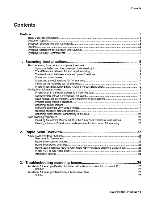
3. Troubleshooting scanning issues........................................................25
Accidental full scan proliferation by folder paths which include build or commit ID............................ 25 Solution......................................................................................................................................25
Contents
Contents
Preface....................................................................................................5
1. Scanning best practices......................................................................... 8
API Spec 5CT油套管规范
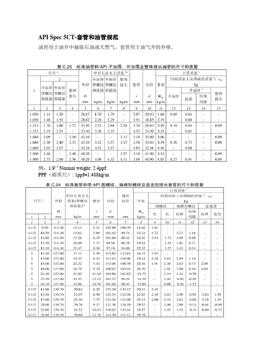
API Spec 5CT-套管和油管规范
油管用于油井中抽取石油或天然气,套管用于油气井的井壁。
例:1.9’’ Normal weight: 2.4ppf.
PPF(磅英尺): 1ppf=1.488kg/m
API Spec 5ST-连续油管规范
钢级:CT70,CT80,CT90,CT100和CT110
外径规格:0.75’’(19.1mm)-3.5’’(88.9)
钢厂:宝鸡石油钢管φ25.4-φ88.9 mm
连续油管CT(coiled tubing):由长度大于61m的钢管制成的管子称之为连续油管。
该标准不包括无缝管的对接。
一卷连续油管长几千米。
可以代替常规油管进行很多作业,连续油管作业设备具有带压作业、连续起下的特点,设备体积小,作业周期快,成本低。
API Spec 5LCP-连续管线管规范
钢级:X52C, X56C, X60C, X65C, X70C 和X80C (字母C代表连续管)
外径规格:0.5’’(12.7mm)-6 5/8’’(168.3)。
API SPEC 5L 46版纠错
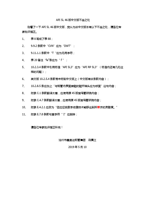
API 5L 46版中文版不当之处
刚看了一下API 5L 46版中文版,我认为该中文版本有以下不当之处,请各位专家批评指正。
1、表8写成了表88;
2、9.9.2条款中“CVN”应为“DWT”;
3、9.11.1.1条款中“T“应为无用字符;
4、表20备注“fe”条应为“ f ”;
5、10.2.3.4条款中引用标准“API 5L3”应为“API RP 5L3”(标准内还有几处这
样的问题);
6、英文版10.2.5.4条款号未标到中文版上(中文版有该条款内容);
7、10.2.8.5条应加上“与钢管内表面接触的触杆端头应为球面”这句内容;
8、附录C.1条款翻译太差,应使用原45版宝鸡管研院内容;
9、附录C.4.7条款翻译太差,应使用原45版宝鸡管研院内容;
10、附录E.4.2.1应改为“但应证实数字成像技术能够达到所要求的灵敏度。
”
11、附录E.7.8条款句首字符“ I”应删除;
请各位专家批评指正补充!
沧州市鑫宜达钢管集团冯镇江
2019年5月10。
API Spec Q1标准培训教材 [兼容模式]
![API Spec Q1标准培训教材 [兼容模式]](https://img.taocdn.com/s3/m/a93cc717eff9aef8941e0619.png)
质量管理八项基本原则
•
a) 以顾客为关注焦点; b) 领导作用; c) 全员参与; d) 过程方法; e) 管理的系统方法; f) 持续改进; g) 基于事实的决策方法; h) 与供方互利的关系。
12
3
2013/5/22
以顾客为关注焦点
领导作用
以顾客为关注焦点 持续改进
全员参与 与供方互利的关系
7
7
API Spec. Q1要求的21个文件
序 号 1 2 标准条款 4.2.3.1 6.2.2.1 要求内容原文 应使用总目录表或相当控制点来标识质量管理体系要求的文件以及 这些文件的现行修改状态。 组织应建立控制点(见3.1.4)和为在质量管理体系中从事活动的人 员提供培训需求。培训要求应是提供质量管理体系的培训和人员的 工作培训。培训频率应由组织予以规定。 作培 培 频率应由组织 以规定 当由外部提供产品要求时,组织应确定方法和建立控制点(见 3.1.4),从而将这些要求转化为产品实现的过程。 组织应建立控制点(见3.1.4),以审核与产品有关的要求。 组织应为产品设计建立控制点(见3.1.4)。 组织应对产品设计输入要求进行标识、文件化和评审。设计和开发 输入应包括顾客规定的要求(见7.2.2)。 组织应为采购过程和供方选择建立控制点(见3.1.4)。
管理的系统方法
• 针对设定的目标,识别、理解并管理一个由相互关联的过程所组 成的体系,有助于提高组织的有效性和效率。 • 在ISO9000中列出了建立和实施质量管理体系的十三个步骤,包括: 确定顾客的需求和期望,建立组织的质量方针和目标,确定过程 和职责,确定过程有效性的测量方法并用来测定现行过程的有效 性,防止不合格,寻找改进机会,确定改进方向,实施改进,监 控改进效果,评价结果,评审改进措施和确定后续措施等。 • 这种建立和实施质量管理体系的方法,既可用于新建体系,也可 用于现有体系的改进。此方法的实施可在三方面受益:一是提供 对过程能力及产品可靠性的信任 二是为持续改进打好基础 三 对过程能力及产品可靠性的信任;二是为持续改进打好基础;三 是导致顾客满意,最终结果是组织获得成功。 • a) 组织实施本原则的主要利益 • A、 使各过程彼此协调一致,能最好地取得所期望的结果; • B、 增强了把注意力集中于关键过程的能力; • C、 能向关键的相关方提供对组织的有效性和效率的信任。 • b) 组织实施本原则一般要采取的主要措施 • A、 建立一个体系内诸过程的内在依赖关系; • B、 了解体系内诸过程的内在依赖关系; • C、 关注并确定在体系内特定过程应如何运作; 18 • D、 通过测量和评价持续改进体系。
Windows XP系统目录下文件夹介绍

Windows XP系统windows目录下文件夹功能介绍├—WINDOWS│ ├—system32(存放Windows的系统文件和硬件驱动程序)│ │ ├—config(用户配置信息和密码信息)│ │ │ └—systemprofile(系统配置信息,用于恢复系统)│ │ ├—drivers(用来存放硬件驱动文件,不建议删除)│ │ ├—spool(用来存放系统打印文件。
包括打印的色彩、打印预存等)│ │ ├—wbem(存放WMI测试程序,用于查看和更改公共信息模型类、实例和方法等。
请勿删除)│ │ ├—IME(用来存放系统输入法文件,类似WINDOWS下的IME文件夹)│ │ ├—CatRoot(计算机启动测试信息目录,包括了计算机启动时检测的硬软件信息)│ │ ├—Com(用来存放组件服务文件)│ │ ├—ReinstallBackups(电脑中硬件的驱动程序备份)│ │ ├—DllCache(用来存放系统缓存文件。
当系统文件被替换时,文件保护机制会复制这个文件夹下的文件去覆盖非系统文件)│ │ ├—GroupPolicy(组策略文件夹)│ ││├—system(系统文件夹,用来存放系统虚拟设备文件)│ ├—$NtUninstall$(每给系统打一个补丁,系统就会自动创建这样的一个目录,可删除)│ ├—security(系统安全文件夹,用来存放系统重要的数据文件)│ ├—srchasst(搜索助手文件夹,用来存放系统搜索助手文件,与msagent 文件夹类似)│ ├—repair(系统修复文件夹,用来存放修复系统时所需的配置文件)│ ├—Downloaded Program Files(下载程序文件夹,用来存放扩展IE功能的ActiveX等插件)│ ├—inf(用来存放INF文件。
INF文件最常见的应用是为硬件设备提供驱动程序服务,不建议删除其中文件)│ ├—Help(Windows帮助文件)│ ├—Config(系统配置文件夹,用来存放系统的一些临时配置的文件)│ ├—msagent(微软助手文件夹,存放动态的卡通形象,协助你更好地使用系统。
ISP_5_QUG_CHS说明书
™Pro 5目录1.介绍 (4)2.软件安装 (5)2.1 重要提示 (5)2.2 注意 (5)2.3 安装 (5)2.4 激活 (7)3.支持的文档 (7)4.扫描仪概述 (8)4.1 顶视图 (8)4.2 前视图 (8)4.3 后视图 (9)4.4 侧视图 (9)5.准备扫描仪 (10)6.使用 IRIScan Pro 5 (10)7.扫描文档 (11)7.1 使用自动送纸器 (11)7.2 使用前端进纸盘 (14)7.3 使用后端进纸盘 (15)7.4 从对面的托盘中弹出文档 (15)8.维护 (16)8.1 清洁扫描仪玻璃、分离垫和辊 (16)8.2 更换进纸辊 (17)8.3 更换分离垫 (18)9.故障排除 (18)9.1 清除卡纸 (18)9.2 错误状况 (19)9.3 问答 (19)9.4 产品支持 (20)10.规格 (21)10.1 扫描仪规格 (21)10.2 系统要求 (22)11.法律信息 (23)1.介绍本快速入门用户指南旨在帮助您开始使用IRIScan™ Pro 5彩色馈纸式扫描仪扫描仪。
操作扫描仪及其软件之前,请先阅读本指南。
所有信息可能变更,恕不另行通知。
IRIScan™ Pro 5 扫描仪捆绑不同的软件包。
有关我们软件的更多信息和详细指南:IRISmart™File/Invoice、Readiris™、Cardiris™、Button Manager 和Capture Tool,请参阅上的对应文档。
2.软件安装2.1 重要提示2.2 注意请勿将扫描仪放在阳光直射之处。
直接暴露于阳光或过热的地方,可能会导致设备损坏。
请勿将扫描仪安装在潮湿或多尘的地方。
请务必使用正确的交流电源。
将扫描仪牢固放置于平坦的表面。
倾斜或不平坦的表面可能会导致机械问题或进纸问题。
请保留扫描仪包装箱和包装材料以便将来运输。
2.3 安装1.请访问/start。
2.向下滚动到IRIScan™ Pro 5。
W9412G6JH-5I;中文规格书,Datasheet资料

Read Operation............................................................................................................. 12 Write Operation ............................................................................................................. 13 Precharge ..................................................................................................................... 13 Burst Termination ......................................................................................................... 13 Refresh Operation ........................................................................................................ 13 Power Down Mode ....................................................................................................... 14 Input Clock Frequency Change during Precharge Power Down Mode ........................ 14 Mode Register Operation .............................................................................................. 14 Publication Release Date: Nov. 29, 2011 Revision A03
伯南克ATP云恶意软件检测API设置指南说明书
Table of ContentsThreat Intelligence Open APIThreat Intelligence Open APIJuniper Advanced Threat Prevention Cloud (Juniper ATP Cloud) provides the following APIs that can help you keep your network free of sophisticated malware and cyberattacks by using superior cloud-based protection:Threat Intelligence API OverviewThe Threat Intelligence open API allows you to program the Juniper ATP Cloud Command and Control server (C&C) feeds to suit your requirements. You can perform the following operations using the threat intelligence API:•Inject an IP, URL, or domain into a C&C feed with a threat level from 1 through 10. You can create up to 30 different custom C&C feeds.•An IP can be an IP address, IP range, or IP subnet.•Both IPv4 and IPv6 addresses are supported.•Update the threat level of an IP, URL, or domain from 1 through 10.•Delete a specific server in the feed or delete the entire feed.•Retrieve the current status of an operation (processing) or errors (if any) from the feed processing engine.The Threat Intelligence API supports a Swagger API specification in JSON format to allow programmatic access to it. For more information on the Swagger API specification, see https://threat-/swagger.json.NOTE: Starting in Junos OS 19.2, SRX Series Firewalls support inspection of encrypted traffic(HTTPS) as well as HTTP traffic in threat intelligence feeds. Server name identification (SNI)checks are also supported. These changes do not introduce new CLI commands. Existingcommands make use of this functionality.The following table lists the rate limits (number of requests you can make per minute) for the Threat Intelligence APIs. If you exceed these rate limits, you will receive a 429 - Too many Requests error.Configuration and SetupT o access the API, you must create an application token in the Juniper ATP Cloud Web UI and use that token as the bearer token in the authorization header.T o generate an application token:1.Log in to the Juniper ATP Cloud Web UI using your credentials. Select Administration > ApplicationT okens and click the plus (+) sign. Fill in the name of the token and other required details in the pop-up box that appears and click OK to create a new token. See Figure 1 on page 3.Figure 1: Creating an Application T oken2.A confirmation pop-up message appears, indicating the creation of a new token, as shown in Figure 2on page 3. You can now use this token to access the Juniper ATP Cloud API.Figure 2: Confirming the Creation of an Application T okenNOTE: You can generate a maximum of 10 tokens per user, and each token is valid for oneyear.For more information on how to create application tokens, see Creating Application T okens.Usage ExamplesThe following cURL examples illustrate the use of the threat intelligence API:•curl -k -v -XPOST -H "Authorization: Bearer <TOKEN>" -F file=@/tmp/whitelist.txt <API HOST>/v1/cloudfeeds/ whitelist/file/ip/<FEEDNAME>•curl -k -v -XPOST -H "Authorization: Bearer <TOKEN>" -F file=@/tmp/whitelist.txt <API HOST>/v1/cloudfeeds/cc/ file/ip/<FEEDNAME>where:•API HOST is the name of the Open API hostname corresponding to the location of the customer portal.Please refer to Table 1 on page 5 for the correct hostname for your location.•TOKEN is the application token generated in the Juniper ATP Cloud Web UI.•FEED NAME is the name of the feed you want to create.Juniper ATP Cloud API OverviewYou can perform the following operations using the Juniper ATP Cloud API:•Retrieve the blocklist or allowlist for the specific server type.•Update an IP, URL, or FQDN in a blocklist or allowlist server list.•An IP can be an IP address, IP range, or IP subnet.•Both IPv4 and IPv6 addresses are supported.•Delete a specific server in the list or delete the entire list.The Juniper ATP Cloud API supports a Swagger API specification in JSON format to allow programmatic access to it. For more information on the Swagger API specification, see https:///swagger.json.The following table lists the rate limits (number of requests you can make per minute) for the Juniper ATP Cloud APIs. If you exceed these rate limits, you will receive a 429 - Too many Requests error.NOTE: Juniper ATP Cloud supports up to 3,000 entries in the allowlist and 3,000 entires in the blocklist.Configuration and SetupT o access the API, you must create an application token in the Juniper ATP Cloud Web UI and use that token as the bearer token in the authorization header. See section"Configuration and Setup" on page 2 for more information on the creation of the token.Juniper ATP Cloud URLsJuniper ATP Cloud hostnames varies by location. Please refer to the following table:Table 1: Juniper ATP Cloud URLs by LocationTable 1: Juniper ATP Cloud URLs by Location(Continued)Usage ExampleThe following cURL example illustrates the use of the Juniper ATP Cloud API:•curl -k -v -XPOST -H "Authorization: Bearer <TOKEN>” -F file=@/tmp/blacklist.txt <API HOSTNAME>/v1/skyatp/ blacklist/file/ip/<FEED NAME>where:•API HOST is the name of the Open API hostname corresponding to the location of the customer portal.Please refer to Table 1 on page 5 for the correct hostname for your location.•TOKEN is the application token generated in the Juniper ATP Cloud Web UI.•FEED NAME is the name of the feed you want to create.File/Hash API OverviewThe file/hash API lets you submit files for analysis. You can perform the following operations:•Look up sample malware scores by hash.•Submit samples for malware analysis.•Update an IP, URL, or FQDN from a file in a specific list.•An IP can be an IP address, IP range, or IP subnet.•Both IPv4 and IPv6 addresses are supported.The file/hash API supports a Swagger API specification in JSON format to allow programmatic access to it. For more information on the Swagger API specification, see https:/// swagger.json.Configuration and SetupT o access the API, you must create an application token in the Juniper ATP Cloud Web UI and use that token as the bearer token in the authorization header. See section"Configuration and Setup" on page 2 for more information on the creation of the token.Usage ExampleThe following cURL example illustrates the use of the file/hash API:•curl -H "Authorization: Bearer<TOKEN>” -k <API HOSTNAME>/v1/skyatp/lookup/hash/<SHA256>?full_report=true •curl -H "Authorization: Bearer<TOKEN>” -k -F file=@/srv/sample.exe <API HOSTNAME>/v1/skyatp/submit/sampleNOTE: API HOST is the name of the Open API hostname corresponding to the location of thecustomer portal. Please refer to Table 1 on page 5 for the correct hostname for your location.where:•TOKEN is the application token generated in the Juniper ATP Cloud Web UI.•SHA256 is the sample hash. Only SHA256 is supported at this time.Full reports will be completely supported in an upcoming release. The report you receive right now may slightly different in appearance and content.Infected Host API OverviewThe infected host feed is generated by Juniper ATP Cloud and is used to flag compromised hosts. The feed is dynamic. Hosts are automatically added when Juniper ATP Cloud suspects a host has been compromised (through a proprietary algorithm) and can be manually removed from the list through the user interface once you feel the host is no longer compromised. The feed lists the IP address or IP subnet of the host along with a threat level, for example, xxx.xxx.xxx.133 and threat level 5. This feed is unique to a realm and IP addresses within the real are assumed to be non-overlapping.Associated with the infected host feed are a allowlist and blocklist. These are different from the generic Juniper ATP Cloud allowlist and blocklist. The infected host feed uses these lists to remove hosts that are currently on an infected host feed (allowlist) and to always list a host in the infected host feed (blocklist.)With the infected host API, you can do the following:•Return a list of all IP addresses in the current infected host feed.•Return a list of all IP addresses in the infected host allowlist or blocklist.•Delete an IP address from the infected host allowlist or blocklist.•Add an IP address to the infected host allowlist or blocklist.The infected host API supports a Swagger API specification in JSON format to allow programmatic access to it. For more information on the Swagger API specification, see https:///swagger.json.Configuration and SetupT o access the API, you must create an application token in the Juniper ATP Cloud Web UI and use that token as the bearer token in the authorization header. See section"Configuration and Setup" on page 2 for more information on the creation of the token.IP Filter API OverviewA Dynamic Address Entry (DAE) provides dynamic IP address information to security policies. A DAE is a group of IP addresses, not just a single IP prefix, that can be imported. These IP addresses are for specific domains or for entities that have a common attribute such as a particular undesired location that poses a threat. The administrator can then configure security policies to use the DAE within a security policy. When the DAE is updated, the changes automatically become part of the security policy. There isno need to update the policy manually. Note that this is an IP address-only feed. It does not support URLs or fully qualified domain names (FQDNs).The IP filter APIs let you perform the following tasks:•Remove IP addresses (in a .csv file) from an IP filter feed•Add IP addresses (in a .csv file) to an IP filter feed.•Remove a specific IP address from the IP filter feed.•Add a specific IP address to the IP filter feed.•Remove a specific IP filter feed.•Get the processing status of a specific IP Filter feed.The IP filter API supports a Swagger API specification in JSON format to allow programmatic access to it. For more information on the Swagger API specification, see https:/// swagger.json.Configuration and SetupT o access the API, you must create an application token in the Juniper ATP Cloud Web UI and use that token as the bearer token in the authorization header. See section"Configuration and Setup" on page 2 for more information on the creation of the token.ExampleIn this example, targeted attacked are being performed against web servers in a DMZ while concealing their identities via T or. T or exit nodes move frequently and keeping an up-to-date list of all 1000+ exit nodes within a firewall policy is almost impossible. This can, however, be done easily using Juniper ATP Cloud APIs. For more information on this example, see Automating Cyber Threat Intelligence with Sky ATP.Shown below is an example script that performs the following actions:•Polls the official T orProject's exit-node list via cURL and extracts legitimate IP information via grep.•Utilizes Juniper ATP Cloud open API to install and propagate third-party threat intelligence to all SRX Series Firewalls in the network.•Runs on an hourly basis via cron to ensure that the active T or Relays are always being blocked. #!/bin/bash# Define Application Token (Paste in your value between the "")APPToken="Your_Application_Token_Here"# Define the name of the feed you wish to createFeedName="Tor_Exit_Nodes"#Define temporary file to store address listTorList=/var/tmp/torlist.txt# cURL fetches Tor Relay list from https:///exit-addresses# grep identifies and extracts valid IP addresses from the listcurl -k https:///exit-addresses | grep -E -o'(25[0-5]|2[0-4][0-9]|[01]?[0-9][0-9]?)\.(25[0-5]|2[0-4][0-9]|[01]?[0-9][0-9]?)\.(25[0-5]|2[0-4][0-9]|[01]?[0-9][0-9]?)\.(25[0-5]|2[0-4][0-9]|[01]?[0-9][0-9]?)' > $TorList#Remove old Feed information before uploading new listcurl -k -v -XDELETE -H "Authorization: Bearer $APPToken" -F server='*' https:///v1/cloudfeeds/blacklist/param/ip/${FeedName}# Wait for 5 seconds before uploading new listsleep 5#Upload List to SkyATP as Feed Tor_Exit_Nodescurl -k -v -XPOST -H "Authorization: Bearer $APPToken" -F file=@${TorList} https:///v1/cloudfeeds/blacklist/file/ip/${FeedName}# Cleanuprm $TorList# ExitOnce the script has been run successfully, we can see that the latest T or Nodes are being blocked during an ICMP request below (feed-name=Tor_Exit_Nodes)<14>12016-10-17T15:18:11.618ZSRX-1500RT_SECINTEL-SECINTEL_ACTION_LOG[*********.x.x.x.137 category="secintel" sub-category="Blacklist" action="BLOCK" action-detail="DROP" http-host="N/A" threat-severity="0" source-address="5.196.121.161" source-port="1" destination-address="x.x.0.10" destination-port="24039" protocol-id="1" application="N/A" nested-application="N/A" feed-name="Tor_Exit_Nodes" policy-name="cc_policy" profile-name="Blacklist" username="N/A" roles="N/A" session-id-32="572564" source-zone-name="Outside" destination-zone-name="DMZ"] category=secintel sub-category=Blacklist action=BLOCK action-detail=DROP http-host=N/A threat-severity=0 source-address=x.x.0.110 source-port=1 destination-address=x.x.x.161 destination-port=24039 protocol-id=1 application=N/A nested-application=N/A feed-name=Tor_Exit_Nodes policy-name=cc_policy profile-name=Blacklist username=N/A roles=N/A session-id-32=572564 source-zone-name=Outside destination-zone-name=DMZSRX Series Update Intervals for Cloud FeedsThe following table provides the update intervals for each feed type. Note that when the SRX Series Firewall makes requests for new and updated feed content, if there is no new content, no updates are downloaded at that time.Table 2: Feed Update IntervalsTable 2: Feed Update Intervals (Continued)Open API for DNS CategoryThe following table provides the feed manifest that is downloaded by the SRX Series Firewall. Table 3: Feed ManifestTable 3: Feed Manifest (Continued)RELATED DOCUMENTATIONThreat Intelligence Open API Reference GuideJuniper Sky ATP Open API Reference GuideJuniper Networks, the Juniper Networks logo, Juniper, and Junos are registered trademarks of JuniperNetworks, Inc. in the United States and other countries. All other trademarks, service marks, registeredmarks, or registered service marks are the property of their respective owners. Juniper Networks assumes no responsibility for any inaccuracies in this document. Juniper Networks reserves the right to change,modify, transfer, or otherwise revise this publication without notice. Copyright © 2023 Juniper Networks, Inc. All rights reserved.。
API 8C 第5版2012(PSL1和PSL2)(中文)介绍

钻井和采油提升设备规范(PSL 1和PSL 2)Drilling and Production Hoisting Equipment(PSL 1 and PSL 2)API Spec 8C2012年4月,第5版生效日期:2012年10月1日钻井和采油提升设备规范(PSL 1和PSL 2)目次特别说明 (V)前言 (VI)1 范围 (1)2 规范性引用文件 (1)3 术语、定义和缩略语 (2)3.1 术语和定义 (2)3.2 缩略语 (4)4 设计 (4)4.1 总则 (4)4.2 设计条件 (4)4.3 强度分析 (4)4.4 尺寸级别 (6)4.5 接触表面半经 (7)4.6 额定值 (7)4.7 设计安全系数 (7)4.8 剪切强度 (7)4.9 坠落物体 (7)4.10 特定设备 (7)4.11 设计文件 (7)5 设计验证试验 (8)5.1 总则 (8)5.2 试验产品的抽样 (8)5.3 试验程序 (8)5.4 额定载荷值的确定 (9)5.5 设计验证试验程序和额定值确定的另一种方法 (9)5.6 载荷试验装置 (9)5.7 设计更改 (9)5.8 记录 (9)6 材料要求 (9)6.1 总则 (10)6.2 书面规范 (10)6.3 力学性能 (10)6.4 材料鉴定 (10)6.5 制造 (11)6.6 化学成分 (11)7 焊接要求 (11)7.1 总则 (11)7.2 焊接评定 (11)7.3 书面文件 (14)7.4 焊料控制 (14)IAPI Spec 8C7.5 焊缝性能 (14)7.6 焊后热处理 (14)7.7 组焊焊缝 (14)7.8 补焊焊缝 (14)8 质量控制 (15)8.1 总则 (15)8.2 质量控制人员资格 (15)8.3 测试设备 (15)8.4 特定设备和零部件的质量控制 (15)8.5 尺寸检验 (19)8.6 验证载荷试验 (19)8.7 静水压试验 (19)8.8 功能试验 (19)8.9 要求确认的过程 (19)9 设备 (20)9.1 总则 (20)9.2 提升滑轮 (20)9.3 游车 (21)9.4 游车与大钩的连接件 (22)9.5 连接件、连接耳和钻杆吊卡连接耳 (22)9.6 钻井大钩 (22)9.7 吊环 (23)9.8 吊卡 (23)9.9 旋转水龙头 (28)9.10 动力水龙头 (29)9.11 动力短节 (29)9.12 死绳固定器 (29)9.13 钻柱运动补偿器 (29)9.14 压力容器和管线 (30)9.15 滚动轴承 (30)9.16 能用作提升设备的安全卡瓦 (30)9.17 导向小车 (30)10 标志 (31)10.1 产品标志 (31)10.2 额定值标志 (31)10.3 组合设备标志 (31)10.4 构件的可追溯性 (31)10.5 出厂编号 (32)10.6 标志方法 (32)11 文件 (32)11.1 总则 (32)11.2 制造商保存的文件 (32)11.3 设备携带的随机文件 (32)附 录 A (规范性附录)附加要求 (34)A.1 总则 (34)A.2 SR 1验证载荷试验 (34)II钻井和采油提升设备规范(PSL 1和PSL 2)A.3 SR 2低温试验 (34)A.4 SR 3数据手册 (34)A.5 SR 4铸件的附加体积检测 (34)A.6 SR 5锻造材料的体积检测 (34)A.7 SR 6后扩孔应力释放结构 (35)附 录 B (资料性附录)热处理设备的鉴定指南 (36)B.1 温度公差 (36)B.2 炉子的校验 (36)B.2.1 总则 (36)B.2.2 记录 (36)B.2.3 间歇式热处理炉法 (36)B.2.4 连续式热处理炉法 (36)B.3 仪表 (36)B.3.1 总则 (36)B.3.2 准确度 (36)B.3.3 校验 (37)附 录 C (资料性附录) API会标 (38)C.1 引言 (38)C.2 引用文件 (38)C.3 API会标纲要:许可证持有者的职责 (38)C.3.1 持有许可证,使用API会标 (38)C.3.2 会标产品与API Q1的符合性 (38)C.3.3 API会标的使用 (38)C.3.4 记录 (39)C.3.5 质量纲要的更改 (39)C.3.6 广告时使用API会标 (39)C.4 产品标志要求 (39)C.4.1 总则 (39)C.4.2 产品规范标识 (39)C.4.3 美国惯用(USC)单位的使用 (39)C.4.4 许可证编号 (39)C.5 API会标纲要:API职责 (39)参考文献 (40)图1 RSC额定载荷值(无应力释放槽情况) (6)图2 等效圆模型-长度L的实体 (12)图3 等效圆模型-管子(任何截面) (12)图4 等效圆模型-复杂形状 (12)图5 等效圆模型-基尔试块结构 (13)图6 基尔试块尺寸推导计算示例 (13)图7 滑轮绳槽 (20)图8 游车和大钩提环 (25)图9 大钩和水龙头提环接触表面半径 (25)图10 吊环和大钩、吊卡连接耳接触表面半径 (26)图11 套管和油管吊卡孔径 (27)图12 旋转水龙头连接 (27)IIIAPI Spec 8C表1 设计安全系数 (7)表2 伸长率要求(PSL 2) (10)表3 小尺寸冲击试样的调整系数 (10)表4 PSL 1—最大允许缺陷等级 (16)表5 PSL 2—最大允许缺陷等级 (16)表6 提升工具接触表面半径 (22)表7 钻杆吊卡孔径和标志 (23)表8 不加厚套管和油管吊卡孔径 (24)表9 加厚油管吊卡孔径 (24)表10 死绳固定器额定载荷值 (29)表11 设计安全系数 (30)IV钻井和采油提升设备规范(PSL 1和PSL 2)特别说明API出版物只能针对一些共性问题。
展锐 Paddle Lite 模型 Android NNAPI 部署指南说明书

Paddle Lite模型Android NNAPI部署指导手册文档版本V1.1发布日期2023-05-12文档版本V1.1 (2023-05-12)版权所有 © 紫光展锐(上海)科技有限公司i版权所有 © 紫光展锐(上海)科技有限公司。
保留一切权利。
本文件所含数据和信息都属于紫光展锐(上海)科技有限公司(以下简称紫光展锐)所有的机密信息,紫光展锐保留所有相关权利。
本文件仅为信息参考之目的提供,不包含任何明示或默示的知识产权许可,也不表示有任何明示或默示的保证,包括但不限于满足任何特殊目的、不侵权或性能。
当您接受这份文件时,即表示您同意本文件中内容和信息属于紫光展锐机密信息,且同意在未获得紫光展锐书面同意前,不使用或复制本文件的整体或部分,也不向任何其他方披露本文件内容。
紫光展锐有权在未经事先通知的情况下,在任何时候对本文件做任何修改。
紫光展锐对本文件所含数据和信息不做任何保证,在任何情况下,紫光展锐均不负责任何与本文件相关的直接或间接的、任何伤害或损失。
请参照交付物中说明文档对紫光展锐交付物进行使用,任何人对紫光展锐交付物的修改、定制化或违反说明文档的指引对紫光展锐交付物进行使用造成的任何损失由其自行承担。
紫光展锐交付物中的性能指标、测试结果和参数等,均为在紫光展锐内部研发和测试系统中获得的,仅供参考,若任何人需要对交付物进行商用或量产,需要结合自身的软硬件测试环境进行全面的测试和调试。
商标声明、、、展讯、Spreadtrum 、SPRD 、锐迪科、RDA 及其他紫光展锐的商标均为紫光展锐(上海)科技有限公司及/或其子公司、关联公司所有。
本文档提及的其他所有商标或注册商标,由各自的所有人拥有。
免责声明本文档可能包含第三方内容,包括但不限于第三方信息、软件、组件、数据等。
紫光展锐不控制且不对第三方内容承担任何责任,包括但不限于准确性、兼容性、可靠性、可用性、合法性、适当性、性能、不侵权、更新状态等,除非本文档另有明确说明。
- 1、下载文档前请自行甄别文档内容的完整性,平台不提供额外的编辑、内容补充、找答案等附加服务。
- 2、"仅部分预览"的文档,不可在线预览部分如存在完整性等问题,可反馈申请退款(可完整预览的文档不适用该条件!)。
- 3、如文档侵犯您的权益,请联系客服反馈,我们会尽快为您处理(人工客服工作时间:9:00-18:30)。
API SPEC 5L管线钢管管线钢管1 1 范围范围范围1.1 1.1 适用范围适用范围制定本标准的目的是为给石油天然气工业中输气、输水、输油用管提供一个适用的标准。
本标准适用于无缝钢管和焊接钢管,其中包括普通端口、螺纹端口、承插端口的管及直通流线管(TFL )和端口已为特殊连接做好加工的管。
虽然符合本标准的普通端口的钢管主要是供工地现场环形对焊之用,但制造厂对现场焊接将不承担责任。
1.2 1.2 产品等级(产品等级(产品等级(PSL PSL PSL))本标准规定了两种产品规范等级(PSL1和PSL2)。
此两种PSL 等级的产品所规定的标准技术要求水平不一样,PSL2对碳当量、缺口韧性、最大屈服强度、最大抗拉强度有强制性要求。
这里所述及其他方面的区别在附录J 中有论述。
可以明确要求只以PSL1或PSL2级供货,没有明确要求的则任选其一供货。
无论是订购PSL1或PSL2级的产品,需方还可附加要求。
本标准有补充要求(附录F )和其他可选项目(4.2和4.3)。
1.3 1.3 钢级钢级钢级本标准所涉及的钢级(见注释)有A25、A 、B 、X42、X46、X52、X56、X60、X65、X70、X80及任一中间钢级(钢级高于X42的两相邻标准级的中间级由供需双方协商)。
PSL1级的管,以A25至X70级钢供货;PSL2级的管,以B 至X80级钢供货。
Ⅱ类钢(ClⅡ)是回磷钢,大多数情况下比Ⅰ类钢(ClⅠ)具有更好的螺纹加工性能。
原因是Ⅱ类钢的磷含量较Ⅰ类钢高,使其弯曲起来要难一些。
未经需方许可,供方不得用X60或以上钢级的钢管代替其所订购的X52级或以下钢级的钢管。
注释:钢级的代号是相对的,A 级、B 级没有标出其最小屈服强度参数;其他钢级代号是由字母A 或X 加美制单位规定的最小屈服强度的首两位数组成的。
1.4 1.4 尺寸规格尺寸规格尺寸规格本标准中的尺寸规格是相对单位制下的表示方法,数值是美制单位对管子的外径尺寸测量而产生的。
文中及表中所列规格为管子尺寸的简便参考(不用作定货规定)。
管的尺寸规格等于或大于23/8(in.)时,以整数加分数表示 ;管的尺寸规格小于23/8(in.)时,(分数部分)用三位小数表示。
这些尺寸规格替代了本标准以前版本中使用的“尺寸规格”及“公称尺寸”。
考虑到习惯于按公称尺寸而非外径尺寸的本标准的用户,为使他们熟悉本标准中这些新的尺寸规格,特别用在表4、表5和6A 中。
PSL1级的管可提供的(外径)尺寸范围:0.405 ~ 80(in.);PSL2级的管可提供的(外径)尺寸范围:4 1/2 ~ 80(in.)。
螺纹和螺纹量规的尺寸要求、量规检测实施规定、量规技术条件和证书,以及螺纹检验的仪器和方法,均列入API Std 5B 中,并适用于本标准中所包括的所有螺纹加工产品。
1.5 1.5 单位单位单位本标准中所使用的数值单位为美制单位;文中和一些表中括弧内的数值为国际标准单位(米制)。
每一单位制项下的数值(换算后)不尽完全等值,因此使用须是相对独立的,不允许以任何方式混制组合使用。
有关两单位制换算的换算系数及数值修约规定可参阅附录M。
2 2 引用标准引用标准引用标准2.1 本标准所引用的下列API 标准和其他工业标准,无论是全部引用还是部分引用,均为最新版本: API(美国石油学会)RP 5A3 套管、油管和管线用钢管的螺纹配合Spec 5B 套管、油管和管线用钢管螺纹的加工、测量和检验规范RP 5L1 管线钢管铁路运输的推荐操作规程RP 5L3 管线钢管落锤撕裂试验的推荐操作规程RP 5LW 管线钢管船运的推荐操作规程Std 1104 管道焊接及相关设备AAR(美国铁路协会)Section 1 敞蓬车厢载运货物的一般规定Section 2 敞蓬车厢载运钢产品(钢管)的规定ASME (美国机械工程师学会)ASME 锅炉和压力容器标准第Ⅸ部分:电焊和钎焊的质量鉴定ASME 承压用管标准B31.8:输气配管系统ASTM (美国实验与材料学会)A370 钢产品力学性能试验方法和定义A751 钢产品化学分析方法、试验及术语E4 实验机载荷校验方法E8 金属材料拉伸试验方法E29 确定试验数据有效位数符合标准规定的使用方法E83 引伸计的校验方法2.2 本标准所涉及的引用标准之要求,对生产设备的安全性和可互换性是必不可少的。
2.3 本标准中的引用标准亦可用能够证明其符合上述引用标准之要求的其他国际标准或国家标准代替。
使用其他标准代替本标准中之引用标准的制造厂商要对所提供的等效标准证明资料负责。
3 3 术语及定义术语及定义术语及定义下列术语对本标准适用:3.1 3.1 车载量车载量车载量 carload carload从钢管加工厂运出时,一节有轨机车车厢的成品钢管的装载量。
3.2 3.2 (不合格)缺陷(不合格)缺陷 defect defect(材料上带有的)一种缺欠程度达到足以根据本标准之规定判定其为不合格时,称为(不合格)缺陷。
3.3 3.3 熔炼(批)熔炼(批) heat heat一炉熔炼的一个工艺周期内生产的金属(将一定量的金属原料,通常为一炉,熔化后再制成凝固金属的单循环过程)。
3.4 3.4 熔炼分析熔炼分析 heat analysis heat analysis由金属生产厂提供报告的代表一个熔炼批(原料元素)的化学分析。
3.5 3.5 瑕疵瑕疵瑕疵 imperfection imperfection用本标准所列方法可检出的断续的、不规则的小缺陷。
3.6 3.6 检验批检验批 inspection lot inspection lot具有一致受检属性的、在相同条件下生产的一定数量的产品。
3.7 3.7 制造厂制造厂 manufecture manufecture指能确保其产品符合本标准要求的工厂、公司、企业团体。
制造厂可以是一个钢管生产厂,亦可是一个管加工厂、管接头制造厂或管螺纹加工厂。
制造厂对产品完全依照本标准所列条款生产负责。
3.8 3.8 可以(可)可以(可) may maymay 作为动词时表示该条款是可选的。
3.9 3.9 钢管生产厂钢管生产厂 pipe mill pipe mill使用管加工设备(生产钢管)的工厂、公司、企业团体。
3.10 3.10 钢管加工厂钢管加工厂 processor processor拥有对钢管生产厂生产的钢管进行热处理的设备的工厂、公司或企业,它可以是一个“钢管制造厂”(pipe mill)。
3.11 3.11 成品分析成品分析 product analysis product analysis成品钢管、钢板或焊接钢管的坯料的化学分析。
3.12 PSL 3.12 PSL(产品分类等级(产品分类等级(产品分类等级)) product specification le product specification lev v el el产品分类等级之英文(product specification level)首字母缩写。
3.13 3.13 应…应…应… shall shall用来表示该条款为强制性条款。
3.14 3.14 宜…宜… should should用来表示该条款为非强制性条款,但作为一个好的实施方法推荐执行。
3.15 3.15 特殊工艺(特别处理工艺)特殊工艺(特别处理工艺) special processes special processes指钢管制造过程的最终操作(工艺),以使产品符合标准的要求(化学性能和尺寸范围除外)。
可采用如下工艺:制造条件 特殊工艺───────────────────────────────────────a. 无缝管:1. 轧制状态(不扩径) 最终再加热和热定径或张力减径;如有要求,(可增加)冷加工精整和补焊;无损探伤检验。
2. 轧制状态(扩径) 扩径、无损探伤检验、补焊。
3. 热处理 热处理、无损探伤检验、补焊。
b. 无填充金属焊管:1. 轧制状态(不扩径) 焊缝焊接、无损探伤检验、定径;如有要求,(可增加)焊缝热处理和补焊。
2. 轧制状态(扩径) 焊缝焊接、扩径、无损探伤检验;如有要求,(可增加)焊缝热处理和补焊。
3. 热处理 焊缝焊接、整管热处理、无损探伤检验;如有要求(可增加)补焊。
c. 有填充金属焊管:1. 轧制状态(不扩径) 钢管成型、焊缝焊接、无损探伤检验及补焊。
2. 轧制状态(扩径) 焊缝焊接、扩径、无损检验及补焊。
3. 热处理 焊缝焊接、无损探伤检验、补焊及整管热处理。
4. 轧制状态 焊缝焊接、定径及无损探伤检验。
───────────────────────────────────────4 4 订货要求订货要求(见注释1)4.1 需方在订购按API Spec 5L 标准生产的管线用钢管时,应在合同上注明下列内容:───────────────────────────────────────内容名称 参考条款───────────────────────────────────────标准(规范)代号 API Spec 5LPSL(产品分类等级) 1.2和表1订货数量钢级(如有类别要求,须在此注明) 表2、表3钢管种类 5.1.3尺寸规格或管的外径 7.1壁厚 7.1公称长度 7.5和表11管端加工 7.9 交货日期及装运说明4.2 需方还可在合同中注明下列选择性规定:───────────────────────────────────────内容名称 参考条款合格证书(一般) 12.1合格证书(附有试验结果的) 12.1和SR15冷扩径管或无须扩径的管 5.2高碳当量的管 6.1.3.2可选断裂韧性试验:试验类型、温度及夏比冲击功值 6.2.6、SR5、SR6、SR19 对接管的允许最大百分率及验收 7.7螺纹端口管的对接 7.7螺纹保护器 7.9.2要求对壁厚减少负偏差 表9和表10拧接力度要求(机紧拧接) 7.9.2Spec 5L 特殊规定的管端和接箍 7.9.2普通端口钢管坡口加工选择 7.9.3静水压试验压力最小值 9.4.3静水压试验压力最大值 9.4.3电焊钢管焊缝的特殊检验 9.7.2.2、SR17激光焊缝检验的选择 9.7.2.3、SR17无缝钢管的无损检验 9.7.2.6、SR4射线检验的透度计类型 9.7.3.4钢管的涂层:无涂层、临时涂层及特殊涂层 11.1对分层的特殊无损检验 7.8.10磁粉探伤检验方法的功率说明 9.7.5.2直通流线管(TFL) SR7TFL管的对接允许量及长度偏差 SR7.2标志要求:选择长度单位 10.5、I.5不与标准内容相冲突的附加标志 10.1.3、I.1.3尺寸规格≥16 in. 焊管的标志部位和顺序 10.2c、I.2.3钢管或钢板的模压标志 10.7、I.7管子对接的焊接方法 A.1需方检查 9.7.1及附录H检查地点 H.2会标标志(见注释2) I.2─────────────────────────────────────── 4.3 下列各项须经供需双方协商确定:4.3─────────────────────────────────────── 内容名称 参考条款电焊焊缝的热处理工艺选择 5.1.3.3激光焊焊缝的热处理工艺选择 5.1.3.4B级钢钢管的淬火 + 回火处理 5.4管端口处钢带头的焊接 5.5化学成分 6.1.1中间钢级 6.1.1、6.2.1碳当量的限制(对PSL2的钢管):X80级钢 6.1.3.2.壁厚>0.800 in.(20.3mm)的无缝钢管 6.1.3.2高碳当量钢管 6.1.3.2选择断裂韧性试验之夏比试样尺寸 SR5.3落锤撕裂试验试样的缺口类型 SR6.3内径尺寸公差 7.2中间规格管径 7.1中间规格壁厚 7.1钢带对头焊接 7.7带螺纹上接箍管的静水压试验 9.4.1较高压静水压试验压力 9.4.3静水压产生的应力大于最小屈服强度的90%时,管端负荷的补偿 9.4.3、附录K补充静水压试验 9.4.4非标准水压试验的直径尺寸偏差 表7电焊管端口焊缝的无损检验方法 9.7.2.2激光焊管端口焊缝的无损检验方法 9.7.2.3射线检验透度计类型 9.7.3.4选择气体保护金属极电弧焊的复验方法 9.7.4.3选择无缝钢管无损检验的引用标准 SR4.3.2电焊及激光焊(焊缝)的无损检验方法 SR17.2适用于车载量的长度尺寸偏差 表11非标准长度及其尺寸偏差 7.5焊接管接头(接箍) 8.1管体焊补后的无损检验 B.1.1电焊管焊缝的补焊 9.7.4.4、B.1.2激光焊管焊缝的补焊 9.7.4.4、B.1.2焊接热处理管的补焊 B.1.3重新热处理 9.11、SR5.4需方拒收产品的处理 H.4────────────────────────────────────────────────────────────────────────────── 内容名称 参考条款─────────────────────────────────────── 标志要求:不用冲模打印的管接箍的标志 10.1.2、I.1.2(规格<16 in.的焊管,无缝管)内壁标志代替外壁标志 10.2b、I.2.2钢级的彩色标记 10.3.5、I.3.5、SR3非标准长度单位 10.5、I.5长度标志的位置 10.5a、I.5a冷冲模的使用 10.7、I.7───────────────────────────────────────注释:1. 本标准之任何条款不得解释为本学会指明任何材料或生产方法较为优越,亦不可解释为指明采用不同的材料或生产方法时效果一致。
