ANSYS_Reference_Book
ansys中英文对照
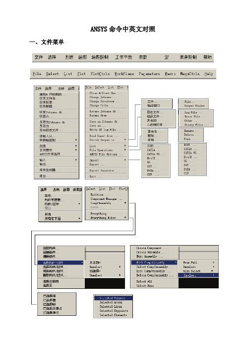
ANSYS命令中英文对照 一、文件菜单二、工具栏三、主菜单1、一级菜单2、二级菜单3、三级菜单4、四级菜单5、五级菜单1、ANSYS12.1 Workbench界面相关分析系统和组件说明【Analysis Systems】分析系统【Component Systems】组件系统【CustomSystems】自定义系统【Design Exploration】设计优化分析类型说明Electric (ANSYS) ANSYS电场分析Explicit Dynamics (ANSYS) ANSYS显式动力学分析Fluid Flow (CFX) CFX流体分析Fluid Flow (Fluent) FLUENT流体分析Hamonic Response (ANSYS) ANSYS谐响应分析Linear Buckling (ANSYS) ANSYS线性屈曲Magnetostatic (ANSYS) ANSYS静磁场分析Modal (ANSYS) ANSYS模态分析Random Vibration (ANSYS) ANSYS随机振动分析Response Spectrum (ANSYS) ANSYS响应谱分析Shape Optimization (ANSYS) ANSYS形状优化分析Static Structural (ANSYS) ANSYS结构静力分析Steady-State Thermal (ANSYS) ANSYS稳态热分析Thermal-Electric (ANSYS) ANSYS热电耦合分析Transient Structural(ANSYS) ANSYS结构瞬态分析Transient Structural(MBD) MBD 多体结构动力分析Transient Thermal(ANSYS) ANSYS瞬态热分析组件类型说明AUTODYN AUTODYN非线性显式动力分析BladeGen 涡轮机械叶片设计工具CFX CFX高端流体分析工具Engineering Data 工程数据工具Explicit Dynamic(LS-DYNA)LS-DYNA 显式动力分析Finite Element Modeler FEM有限元模型工具FLUNET FLUNET 流体分析Geometry 几何建模工具Mechanical APDL 机械APDL命令Mechanical Model 机械分析模型Mesh 网格划分工具Results 结果后处理工具TurboGrid 涡轮叶栅通道网格生成工具Vista TF 叶片二维性能评估工具2、主菜单【File】文件操作【View】窗口显示【Tools】提供工具【Units】单位制【Help】帮助信息3、基本工具条【New】新建文件【Open】打开文件【Save】保存文件【Save As】另存为文件【Import】导入模型【Compact Mode】紧凑视图模式【Shade Exterior and Edges】轮廓线显示【Wireframe】线框显示【Ruler】显示标尺【Legend】显示图例【Triad】显示坐标图示【Expand All】展开结构树【Collapse Environments】折叠结构树【Collapse Models】折叠结构树中的Models项【Named Selections】命名工具条【Unit Conversion】单位转换工具【Messages:Messages】信息窗口【Simulation Wizard】向导【Graphics Annotations】注释【Section Planes】截面信息窗口【Reset Layout】重新安排界面4、建模【Geometry】几何模型【New Geometry】新建几何模型【Details View】详细信息窗口【Graphics】图形窗口:显示当前模型状态【Extrude】拉伸【Revolve】旋转【Sweep】扫掠【Skin/Loft】蒙皮【Thin/Surface】抽壳: 【Thin】创建薄壁实体【Surface】创建简化壳【Face to Remove】删除面:所选面将从体中删除。
ansys命令中英文对照(全)

ansys命令中英文对照(全)ANSYS模块简介APDL换行与续行-APDL规定每行72个字符如果要写表达式A=C1+C2 (C1与C2都为表达式可以用B=C1A=B+C2将一行拆成两行来做但是如果不是表达式,而是输入一个命令参数过多的话,可以用续行命令RMORE,格式如下:RMORE, R7, R8, R9, R10, R11, R12这个命令每次也只能输入6个参数,如果多于6个,可以重复使用RMORE就可以输入13-18,19-24等等。
另外,于上面续行相应的是换行,一行命令太短可以使用多个命令共一行$”,没有双引号。
这样就可以将一行变成多行使。
:)换行符是“ANSYS常见术语/命令对照表Utility Menu 实用菜单SA VE_DB 存储数据库RESUME_DB 恢复数据库Select Entity 选择实体Comp/Assembly 组元/集合Plot/Replot 画图/重新画图Pan,Zoom,Rotate…平移,缩放,旋转…WorkPlane(WP) 工作平面Coordinate System(CS) 坐标系Macro 宏Preference…优先设置…Preprocessor 前处理General Postproc 通用后处理TimeHist Postproc 时间历程后处理APDL ANSYS参数化设计语言Line Fillet 在两条线的过渡生成线Arbitrary 任意形状Cylinder 圆柱体Prism 棱柱体Cone 圆锥形Sphere 球形Polygon 多边形Stress 应力Strain 应变Displacement 位移DOF 自由度V on Mises(Stress) 平均应力Contour 等高线(图)Deformed/Undeformed shape 变形后/未变形的形状Results Summary 结果摘要Radiation Matrix 辐射矩阵Modeling 建模Meshing 划分网格Attribute 属性LS (Load Step) 载荷步Abort the program 终止程序added mass/unit length附加质量acrs .弧, 弧线,弧形affine 仿射ambiguous 模棱两可argc:argument count参数的个数argv:argument vector参数数组loads&Opts 载荷和载荷步设置align 对齐;annotation注解,注释,注记,批注annulus 环形antisoropic 各向异性apply u,rot on L图元拾取append 添加area moment of inertia 截面惯性矩arguments 实参base 基类body load 体载荷booleam 布尔boundary condition 边界条件bypass 绕过central china normal university 华中师范大学child 子类cone 圆锥contour 等高线cylinder 圆柱体DBCS double-byte character set双字节字符集deform 变形derived 派生类device context 设备描述表displacement 位移,约束displacement vector sum 合位移等值线图DOF:degrees of freedom 自由度elastic 弹性的EX 弹性模量existing table(在前处理阶段中输入的所有数据将构成ANSYS的集中式数据库,这个数据库由表构成,所以这时应该是已存在的表) exponentiate取幂指数化extension 扩展名extrude 突出,挤压F.E 有限元模型fillet倒圆角frame 帧identifier 标识符inertia 惯性,惯量initial strain初始应变integer 整数intersecting相交的isotropic 各向同性keypoint incrementmatrix 矩阵meshing划分网格MDI 多文档接口normal 正交;法线norm法向量ortho- 正直orthodox正统overlaid覆盖overload 重载pairwise 两两的parent 父类pentagon 五边形polygon 多边形,多角形polynomial 多项式plastic 塑性prism 棱柱projected location 预期位置PRXY 泊松比Query item查询的内容Rasterization 风格化Reaction 反作用reference number 参考编号scale factor 比例因子sbcs单字节字符集,只能表示西文字符,最大支持255个字符。
ansys各菜单中文意思
ANSYS各菜单中文含义
suixh@
பைடு நூலகம்
ANSYS和Pro/E接口方法
Pro/ E 和ANSYS 的连接方法大致可以分为两种: 1、把Pro/ E 的文件存成.IGES的格式,保存的过程中要选“实体”选项,然后在 ANSYS中通过File--Import--IGES导入模型;
2、使用Pro/E—ANSYS 接口程序,具体操作步骤是: 首先保证在同机的同一操作系统下安装有Pro/E和ANSYS两种软件,且Pro/E软件的版 本要低于ANSYS软件的版本。 1) 选择“程序”—ANSYS10.0—Utilities—ANS_AD-MIN ,在出现的对话框中, 选中 “Configuration options”单选按钮后,点击确定。 2) 在“Configuration options”配置选项对话框中,选中“Configure Connection for Pro/ E” 单选按钮,点击确定。 3) 在“Configure ANSYS Connection for Pro/ E”对话框中将“ANSYS Product”设置为 “ANSYS Multiphysics”, 而“ Graphics device name ”设置为“WIN32”,点击确定。 4) 在“Pro/ Engineer installation information”对话框中,在“Pro/ Engineer installation path”文本框中输入Pro/ E 在本机中的安装路径,如:D : \ Program Files \ proeWildfire 2.0 , 点 击确定,完成Pro/ E 与ANSYS 的接口设置。 5 ) 打开Pro/ E , 在菜单中多出一项“ANSYS10.0”, 单击“ANSYS10.0”会出现“ANS Config”和“ANSYS Geom”两个命令项,在Pro/ E 中完成建模后,单击“ANSYS Geom”,可以 将模型直接导入到ANSYS 中,然后就可以在ANSYS中进行相应的设置模型材料、选择单元 、添加约束和载荷、分网以及最后的计算与显示操作。
ANSYS Workbench 14.0超级学习手册(第1章)
ANSYS Workbench 14.0超级学习手册(第1章)ansysworkbench14.0超级学习手册(第1章)第1章ansysworkbench14.0概述本章从总体上对ansysworkbench14.0自带软件包含结构力学模块、流体力学模块等展开详述,同时对ansysworkbench14.0最新资源整合的其他模块展开直观了解,其中包含低频电磁场分析模块ansoftmaxwell、多领域机电系统设计与仿真分析模块ansoftsimplorer、烦躁分析模块ncode及复合材料建模与后处理模块acp等。
同时,本章还以solidworks软件为基准,了解workbench14.0与常用的cad软件展开内置的步骤及方法。
学习目标:(1)介绍ansysworkbench软件各模块的功能;(2)掌握ansysworkbench软件与solidworks软件的集成设置;(3)掌控ansysworkbench平台的常规设置,包含单位设置、外观颜色设置等。
1.1ansys软件简介ansys提供广泛的工程仿真解决方案,这些方案可以对设计过程要求的任何场进行工程虚拟仿真。
全球的诸多组织都相信ansys为它们的工程仿真软件投资带来最好的价值。
ansys软件就是融结构、流体、电场、磁场、声场分析于一体的大型通用型有限元分析软件。
由世界上最小的有限元分析软件公司之一、美国ansys公司研发,它能够与多数cad软件USB,同时实现数据的共享资源和互换。
软件主要包括3个部分:前处理模块,分析计算模块和后处理模块。
(1)前处置模块提供更多了一个强悍的实体建模及网格分割工具,用户可以便利地结构有限元模型。
(2)分析计算模块包括结构分析(线性分析、非线性分析和高度非线性分析)、流体动力学分析、电磁场分析、声场分析、压电分析以及多物理场的耦合分析,可模拟多种物理介质的相互作用,具有灵敏度分析及优化分析能力。
(3)后处理模块可以将计算结果以彩色等值线表明、梯度表明、矢量表明、粒子流迹表明、立体切片表明、透明化及半透明表明(可以看见结构内部)等图形方式表明出,也可以将计算结果以图表、曲线形式表明或输入。
ANSYS中文翻译官方高级手册_adv4

第四章子结构什么是子结构?子结构就是将一组单元用矩阵凝聚为一个单元的过程。
这个单一的矩阵单元称为超单元。
在ANSYS分析中,超单元可以象其他单元类型一样使用。
唯一的区别就是必须先进行结构生成分析以生成超单元。
子结构可以在ANSYS/Mutiphysics,ANSYS/Mechanical和ANSYS/Structural中使用。
使用子结构主要是为了节省机时,并且允许在比较有限的计算机设备资源的基础上求解超大规模的问题。
原因之一如a)非线性分析和带有大量重复几何结构的分析。
在非线性分析中,可以将模型线性部分作成子结构,这样这部分的单元矩阵就不用在非线性迭代过程中重复计算。
在有重复几何结构的模型中(如有四条腿的桌子),可以对于重复的部分生成超单元,然后将它拷贝到不同的位置,这样做可以节省大量的机时。
子结构还用于模型有大转动的情况下。
对于这些模型,ANSYS假定每个结构都是围绕其质心转动的。
在三维情况下,子结构有三个转动自由度和三个平动自由度。
在大转动模型中,用户在使用部分之前无须对子结构施加约束,因为每个子结构都是作为一个单元进行处理,是允许刚体位移的。
另外一个原因b)一个问题就波前大小和需用磁盘空间来说相对于一个计算机系统太庞大了。
这样,用户可以通过子结构将问题分块进行分析,每一块对于计算机系统来说都是可以计算的。
如何使用子结构子结构分析有以下三个步骤:●生成部分●使用部分●扩展部分生成部分就是将普通的有限元单元凝聚为一个超单元。
凝聚是通过定义一组主自由度来实现的。
主自由度用于定义超单元与模型中其他单元的边界,提取模型的动力学特性。
图4-1是一个板状构件用接触单元分析的示意。
由于接触单元需要迭代计算,将板状构件形成子结构将显著地节省机时。
本例中,主自由度是板与接触单元相连的自由度。
图4-1 子结构使用示例使用部分就是将超单元与模型整体相连进行分析的部分。
整个模型可以是一个超单元,也可以象上例一样是超单元与非超单元相连的。
ANSYS电磁场分析指南磁宏

ANSYS电磁场分析指南磁宏磁宏分析是ANSYS中的一种电磁场分析方法,用于模拟磁场中的行为。
它基于麦克斯韦方程组和磁性材料的本质特性,可以用来研究磁场的分布、场强和磁通量等。
以下是使用ANSYS进行磁宏分析的一般步骤:1.创建几何模型:使用ANSYS的几何建模工具创建您要分析的几何体。
您可以使用ANSYS的二维或三维建模功能,根据您的需求选择适当的几何形状。
2.设置材料属性:在进行磁宏分析之前,您需要为模型中的材料定义磁性属性。
这包括磁导率、磁饱和和磁滞等。
可以通过库中的材料属性进行选择,或者根据实际材料的特性手动输入。
如果您使用的是标准材料,可以轻松从ANSYS材料库中选择。
3.设置边界条件:确定分析的边界条件非常重要。
根据您的应用场景,您可以设置边界条件为固定零磁场、非磁性条件或具有特定磁场分布的条件。
对于二维问题,您可以设置边界上的磁通量。
这些边界条件将在后续计算中起作用。
4.生成网格:ANSYS使用有限元方法进行分析,因此需要生成适当的网格。
您可以选择不同的网格生成技术,例如自动网格细化、手动加密和剖面网格。
网格的质量对分析结果的准确性和计算时间都有重要影响。
5.定义分析类型和求解器:在ANSYS中,您可以选择不同的分析类型和求解器来求解磁场问题。
例如,您可以选择求解静态磁场、谐振频率或非线性磁场等。
根据您的需求选择适当的求解器,以获得准确的结果。
6.运行计算:在设置了适当的材料属性、边界条件和网格后,您可以运行计算。
ANSYS将使用选择的求解器进行计算,并在计算结束后生成结果。
7.分析结果:计算完成后,您可以查看和分析生成的结果。
这包括磁场分布图、场强、感应电流和磁通量等。
ANSYS提供了丰富的后处理工具,可以帮助您更好地理解分析结果。
除了这些基本步骤,在进行磁宏分析时还有一些注意事项和技巧:1.材料特性选择:选择适当的磁性材料特性对分析结果至关重要。
根据实际材料数据进行选择,并注意磁导率的非线性特性。
ANSYS界面命令翻译大全综述
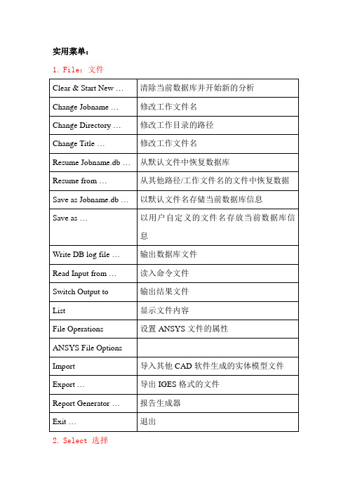
实用菜单:1.File:文件2.Select 选择3.List 列表4.Plot 绘图5.PlotCtrls 绘图控制6.Workplane 工作平面7.Parameters 参数8.Macro 宏9.MenuCtrls 菜单控制10.H elp 帮助ANSYS Toolbar工具条ANSYS Main Menu:ANSYS 主菜单1. Preferences 首选项/偏好设置2. Preprocessor 前处理器2.1 Element Type单元类型2.1.1 Add/Edit/Delete 添加/编辑/删除2.1.2 Switch Elem Type 转换单元类型2.1.3 Add DOF添加自由度2.1.4 Remove DOFs 移除自由度2.1.5 Elem Tech Control 类型的控制2.2 Real Constants实常数2.2.1 Add/Edit/Delete 添加/编辑/删除2.2.2 Thickness Func厚度函数2.3 Material Props材料属性/材料参数2.3.1 Material Library1. Library Path2. Lib Path Status3. Import Library4. Export Library5. Select Units2.2.2 Temperature Units2.2.3 Electromag Units2.2.4 Material Models 材料模型2.2.5 Convert ALPx2.2.6 Change Mat Num2.2.7 Write to File2.2.8 Read from File2.4 Sections截面2.4.1 Section Library1. Library Path2. Import Library2.4.2 Beam梁1. Common Sections2. Custom Sections1. Write From Areas2. Read Sect Mesh3. Edit/Built-up3. Taper Sections1. By XYZ Location2. By Picked Nodes4. Plot Sections5. Sect Control6. NL Generalized 2.4.3 Shell壳1. Lay-up1. Add/Edit2. Plot Sections2. Pre-integrated 2.4.4 Pretension预用力单元1. Pretensn Mesh1. Picked Elements2. Selected Elements3. Element in Line4. Element in Area5. Element in V olu6. With Options1. Divide at Node1. Picked Elements2. Selected Elements3. Element in Line4. Element in Area5. Element in V olu2. Divide at Valu2. Modify Name3. Modify Normal2.4.5 Joints角1. Add/Edit2.4.6 Reinforcing1. Add/Edit2. Display Options1. Normal2. Reinf + Model3. Reinf Only3. Plot Section2.4.7 List Sections2.4.8 Delete Section2.5 Modeling建模2.5.1 Create建立2.5.2 Operate操作1. Extrude2. Extend Line3. Booleans布尔运算3.1 Intersect 交运算3.1.1 Common 一般运算3.1.2 Pairwise 两两相交3.2 Add 加(并、连接、和)3.3 Subtract 减3.4 Divide 切割3.5 Glue 粘接3.6 Overlap 搭接3.7 Partition 分割3.8 Settings3.9 Show Degeneracy4. Scale5. Calc Geom Items2.5.3 Move/Modify移动/修改2.5.4 Copy拷贝2.5.5 Reflect对称映射2.5.6 Check Geom检查几何形状2.5.7 Delete删除2.5.8 Cyclic Sector2.5.9 CMS2.5.10 Genl plane strn2.5.11 Update Geom2.6 Meshing网格划分2.6.1 Mesh Attributes 属性/网格尺寸2.6.2 Mesh Tool网格划分工具2.6.3 Size Cntrls 尺寸控制2.6.4 Mesher Opts2.6.5 Concatenate 连接2.6.6 Mesh 划分网格2.6.7 Modify Mesh2.6.8 Check Mesh2.6.9 Clear2.7 Checking Ctrls单元形状检查控制2.8 Numbering Ctrls编号控制2.9 Archive Model激活模型2.10 Coupling/Ceqn耦合/模拟2.10.1 Couple DOFs 耦合自由度2.10.2 Cupl DOFs w/Mstr 耦合2.10.3 Gen w/Same Nodes 产生耦合2.10.4 Gen w/Same DOF2.10.5 Concident Nodes 连接节点2.10.6 Offset Nodes 偏移节点2.10.7 Del Coupled Sets 删除耦合号2.10.8 Constraint Eqn2.10.9 Gen w/Same DOF2.10.10 Modify ConstrEqn2.10.11 Adjacent Regions2.10.12 Shell/Solid Interface2.10.13 Rigid Region2.10.14 Del Constr Eqn2.11 FLOTRAN set up建立2.12 Multi-Field Set UP 多场设置2.13 Lodes载荷2.14 Physics物理学2.15 Path Operation路径操作3. Solution 求解器3.1 Analysis Type 分析类型3.1.1 New Analysis 为新的分析设定分析类型Static 静态分析Modal 模态分析Harmonic 谐振态分析Transient瞬态分析Spectrum 频谱分析Eigen Buckling 屈曲分析Substructuring 子结构分析3.1.2 Restart 重新启动分析过程3.1.3 Sol’n Controls 求解控制Basic 基本选项Transient 瞬态选项Sol’n Options 求解选项Nonlinear 非线性选项Advanced NL 其他高级非线性选项3.2 Define Loads 定义载荷3.2.1 Settings 施加载荷前的相关设置1. Uniform Temp 设置初始均布温度2. Reference Temp 设置参考温度3. For Surface Ld 设置面载荷梯度4. Replace vs Add 设置重复加载方式3.2.2 Apply 施加相应的载荷3.2.3 Delete 删除不需要的载荷1. All Load Data 所有载荷数据1. All Loads & Opts 删除所有载荷选项2. All SolidMod Lds 删除所有实体模型载荷3. All F.E. Loads 删除所有有限元载荷4. All Inertia Lds 删除所有惯性载荷5. All Section Lds 删除所有部分载荷6. All Constraint 选择性删除所有自由度约束7. All Forces选择性删除所有集中载荷8. All Surface Ld选择性删除所有面载荷9. All Body Loads选择性删除所有实体载荷3.2.4 Operate 载荷的相关操作1. Scale FE Loads 缩放已经施加的载荷大小2. Transfer to FE 将施加在实体模型上的载荷转换到相应的有限元模型上3. Delete Ls Files 删除载荷步文件3.3 Load Step Opts 设置载荷步控制选项3.3.1 Output Ctrls 输出控制1. Output Ctrls 求解打印输出控制2. Grph Solu Track3. DB/Results File 数据库/结果文件输出控制4. Show Status 显示载荷步设置的相关信息5. PGR File3.3.2 Time/Frequenc 时间/频率设置1. Time-Time Step 时间-时间步长设置2. Time and Substps 时间-子步设置3. Time Integration 时间积分设置3.3.3 Nonlinear 非线性设置3.3.2 Other 其他选项设置3.3.3 Stop Solution3.3.4 Reset Options 重设求解设置3.3.5 Read LS File 读入载荷步文件3.3.6 Write LS File 写载荷步文件3.3.7 Initial Stress 初始预应力设置3.4 SE Management (CMS)3.5 Results Tracking3.6 Solve 求解3.6.1 Current LS 从当前载荷步开始求解3.6.2 From LS Files 从特定的载荷步文件开始求解3.6.3 Partial Solu 部分求解3.6.4 Adaptive Mesh 自适应网格求解3.7 Manual Rezoning3.8 Multi-Field Set UP 多场设置3.9 Diagnostics3.10 Unabridged Menu4. General Postproc 通用后处理器4.1 Data &File Opts 数据和文件选项4.2 Results Summary 结果总汇4.3 Read Results 读入结果4.4 Plot Results 绘制结果图4.5 List Results列表显示结果4.6 Query Results查询结果4.7 Options for Outp 输出选项4.8 Results Viewer 结果查看器4.9 Element Table单元表4.10 Path Operations路径操作4.11 Load Case 载荷工况4.12 Check Elem Shape4.13 Write Results4.14 Rom Operations4.15 Fatigue4.16 Define / Modify4.17 Manual Rezoning5. TimeMist Postpro 时间历程后处理器5.1 Variable Viewer 变量观察器5.2 Settings 设置5.3 Store Data 存储数据5.4 Define Variables 定义变量5.5 Read LSDYNA Data5.6 List Variables 列表显示变量5.7 List Extremes5.8 Graph Variables 图形显示变量5.9 Math Operations 数学运算5.10 Table Operations5.11 Smooth Data5.12 Generate Spectrm5.13 Reset Postproc6. Topological Opt 拓扑优化7. ROM Tool8. DesignXplorer9. Design Opt10.Prob Design11.Radiation Opt12.Run-Time Stats13. Session Editor14. Finish 结束QUIT 退出图形对象拾取对话框Single 用鼠标左键单击拾取图形对象,一次只能拾取一个对象。
ANSYS13.0理论参考手册簿
Release 13.0 - © 2010 SAS IP, Inc. All rights reserved.Table of Contents1. Analyzing Thermal Phenomena1.1. How ANSYS Treats Thermal Modeling1.1.1. Convection1.1.2. Radiation1.1.3. Special Effects1.1.4. Far-Field Elements1.2. Types of Thermal Analysis1.3. Coupled-Field Analyses1.4. About GUI Paths and Command Syntax2. Steady-State Thermal Analysis2.1. Available Elements for Thermal Analysis2.2. Commands Used in Thermal Analyses2.3. Tasks in a Thermal Analysis2.4. Building the Model2.4.1. Using the Surface Effect Elements2.4.2. Creating Model Geometry2.5. Applying Loads and Obtaining the Solution2.5.1. Defining the Analysis Type2.5.2. Applying Loads2.5.3. Using Table and Function Boundary Conditions2.5.4. Specifying Load Step Options2.5.5. General Options2.5.6. Nonlinear Options2.5.7. Output Controls2.5.8. Defining Analysis Options2.5.9. Saving the Model2.5.10. Solving the Model2.6. Reviewing Analysis Results2.6.1. Primary data2.6.2. Derived data2.6.3. Reading In Results2.6.4. Reviewing Results2.7. Example of a Steady-State Thermal Analysis (Command or Batch Method)2.7.1. The Example Described2.7.2. The Analysis Approach2.7.3. Commands for Building and Solving the Model2.8. Performing a Steady-State Thermal Analysis (GUI Method)2.9. Performing a Thermal Analysis Using Tabular Boundary Conditions2.9.1. Running the Sample Problem via Commands2.9.2. Running the Sample Problem Interactively2.10. Where to Find Other Examples of Thermal Analysis3. Transient Thermal Analysis3.1. Elements and Commands Used in Transient Thermal Analysis3.2. Tasks in a Transient Thermal Analysis3.3. Building the Model3.4. Applying Loads and Obtaining a Solution3.4.1. Defining the Analysis Type3.4.2. Establishing Initial Conditions for Your Analysis3.4.3. Specifying Load Step Options3.4.4. Nonlinear Options3.4.5. Output Controls3.5. Saving the Model3.5.1. Solving the Model3.6. Reviewing Analysis Results3.6.1. How to Review Results3.6.2. Reviewing Results with the General Postprocessor3.6.3. Reviewing Results with the Time History Postprocessor3.7. Reviewing Results as Graphics or Tables3.7.1. Reviewing Contour Displays3.7.2. Reviewing Vector Displays3.7.3. Reviewing Table Listings3.8. Phase Change3.9. Example of a Transient Thermal Analysis3.9.1. The Example Described3.9.2. Example Material Property Values3.9.3. Example of a Transient Thermal Analysis (GUI Method)3.9.4. Commands for Building and Solving the Model3.10. Where to Find Other Examples of Transient Thermal Analysis4. Radiation4.1. Analyzing Radiation Problems4.2. Definitions4.3. Using LINK31, the Radiation Link Element4.4. Modeling Radiation Between a Surface and a Point4.5. Using the AUX12 Radiation Matrix Method4.5.1. Procedure4.5.2. Recommendations for Using Space Nodes4.5.3. General Guidelines for the AUX12 Radiation Matrix Method4.6. Using the Radiosity Solver Method4.6.1. Procedure4.6.2. Further Options for Static Analysis4.7. Advanced Radiosity Options4.8. Example of a 2-D Radiation Analysis Using the Radiosity Method (Command Method)4.8.1. The Example Described4.8.2. Commands for Building and Solving the Model4.9. Example of a 2-D Radiation Analysis Using the Radiosity Method with Decimation and4.9.2. Commands for Building and Solving the ModelRelease 13.0 - © 2010 SAS IP, Inc. All rights reserved.Chapter 1: Analyzing Thermal PhenomenaA thermal analysis calculates the temperature distribution and related thermal quantities in a system or component. Typical thermal quantities of interest are:•The temperature distributions•The amount of heat lost or gained•Thermal gradients•Thermal fluxes.Thermal simulations play an important role in the design of many engineering applications, including internal combustion engines, turbines, heat exchangers, piping systems, and electronic components. In many cases, engineers follow a thermal analysis with a stress analysis to calculate thermal stresses (that is, stresses caused by thermal expansions or contractions).The following thermal analysis topics are available:•How ANSYS Treats Thermal Modeling•Types of Thermal Analysis•Coupled-Field Analyses•About GUI Paths and Command Syntax1.1. How ANSYS Treats Thermal ModelingOnly the ANSYS Multiphysics, ANSYS Mechanical, ANSYS Professional, and ANSYS FLOTRAN programs support thermal analyses.The basis for thermal analysis in ANSYS is a heat balance equation obtained from the principle of conservation of energy. (For details, consult the Theory Reference for the Mechanical APDL and Mechanical Applications.) The finite element solution you perform via ANSYS calculates nodal temperatures, then uses the nodal temperatures to obtain other thermal quantities.The ANSYS program handles all three primary modes of heat transfer: conduction, convection, and radiation.1.1.1. ConvectionYou specify convection as a surface load on conducting solid elements or shell elements. You specify the convection film coefficient and the bulk fluid temperature at a surface; ANSYS then calculates the appropriate heat transfer across that surface. If the film coefficient depends upon temperature, you specify a table of temperatures along with the corresponding values of film coefficient at each temperature.For use in finite element models with conducting bar elements (which do not allow a convection surface load), or in cases where the bulk fluid temperature is not known in advance, ANSYS offers a convection element named LINK34. In addition, you can use the FLOTRAN CFD elements to simulate details of the convection process, such as fluid velocities, local values of film coefficient and heat flux, and temperature distributions in both fluid and solid regions.1.1.2. RadiationANSYS can solve radiation problems, which are nonlinear, in four ways:•By using the radiation link element, LINK31•By using surface effect elements with the radiation option (SURF151 in 2-D modeling or SURF152 in 3-D modeling)•By generating a radiation matrix in AUX12 and using it as a superelement in a thermal analysis.•By using the Radiosity Solver method.For detailed information on these methods, see Radiation.1.1.3. Special EffectsIn addition to the three modes of heat transfer, you can account for special effects such as change of phase (melting or freezing) and internal heat generation (due to Joule heating, for example). For instance, you can use the thermal mass element MASS71 to specifytemperature-dependent heat generation rates.1.1.4. Far-Field ElementsFar-field elements allow you to model the effects of far-field decay without having to specify assumed boundary conditions at the exterior of the model. A single layer of elements is used to represent an exterior sub-domain of semi-infinite extent. For more information, see Far-Field Elements in the Low-Frequency Electromagnetic Analysis Guide.1.2. Types of Thermal AnalysisANSYS supports two types of thermal analysis:1. A steady-state thermal analysis determines the temperature distribution and other thermalquantities under steady-state loading conditions. A steady-state loading condition isa situation where heat storage effects varying over a period of time can be ignored.2. A transient thermal analysis determines the temperature distribution and other thermalquantities under conditions that vary over a period of time.1.3. Coupled-Field AnalysesSome types of coupled-field analyses, such as thermal-structural and magnetic-thermal analyses, can represent thermal effects coupled with other phenomena. A coupled-field analysis can use matrix-coupled ANSYS elements, or sequential load-vector coupling between separate simulations of each phenomenon. For more information on coupled-field analysis, see the Coupled-Field Analysis Guide.1.4. About GUI Paths and Command SyntaxThroughout this document, you will see references to ANSYS commands and their equivalent GUI paths. Such references use only the command name, because you do not always need to specify all of a command's arguments, and specific combinations of command arguments perform different functions. For complete syntax descriptions of ANSYS commands, consult the Command Reference.The GUI paths shown are as complete as possible. In many cases, choosing the GUI path as shown will perform the function you want. In other cases, choosing the GUI path given in this document takes you to a menu or dialog box; from there, you must choose additional options that are appropriate for the specific task being performed.For all types of analyses described in this guide, specify the material you will be simulating using an intuitive material model interface. This interface uses a hierarchical tree structure of material categories, which is intended to assist you in choosing the appropriate model for your analysis. See Material Model Interface in the Basic Analysis Guide for details on the material model interface.Release 13.0 - © 2010 SAS IP, Inc. All rights reserved.Chapter 2: Steady-State Thermal AnalysisThe ANSYS Multiphysics, ANSYS Mechanical, ANSYS FLOTRAN, and ANSYS Professional products support steady-state thermal analysis. A steady-state thermal analysis calculates the effects of steady thermal loads on a system or component. Engineer/analysts often perform a steady-state analysis before performing a transient thermal analysis, to help establish initial conditions. A steady-state analysis also can be the last step of a transient thermal analysis, performed after all transient effects have diminished.You can use steady-state thermal analysis to determine temperatures, thermal gradients, heat flow rates, and heat fluxes in an object that are caused by thermal loads that do not vary over time. Such loads include the following:•Convections•Radiation•Heat flow rates•Heat fluxes (heat flow per unit area)•Heat generation rates (heat flow per unit volume)•Constant temperature boundariesA steady-state thermal analysis may be either linear, with constant material properties; or nonlinear, with material properties that depend on temperature. The thermal properties of most material do vary with temperature, so the analysis usually is nonlinear. Including radiation effects also makes the analysis nonlinear.The following steady-state thermal analysis topics are available:•Available Elements for Thermal Analysis•Commands Used in Thermal Analyses•Tasks in a Thermal Analysis•Building the Model•Applying Loads and Obtaining the Solution•Reviewing Analysis Results•Example of a Steady-State Thermal Analysis (Command or Batch Method)•Performing a Steady-State Thermal Analysis (GUI Method)•Performing a Thermal Analysis Using Tabular Boundary Conditions•Where to Find Other Examples of Thermal Analysis2.1. Available Elements for Thermal AnalysisThe ANSYS and ANSYS Professional programs include about 40 elements (described below) to help you perform steady-state thermal analyses.For detailed information about the elements, see the Element Reference, which manual organizes element descriptions in numeric order.Element names are shown in uppercase. All elements apply to both steady-state and transient thermal analyses. SOLID70 also can compensate for mass transport heat flow from a constant velocity field.Table 2.1 2-D Solid ElementsTable 2.2 3-D Solid ElementsTable 2.3 Radiation Link ElementsTable 2.4 Conducting Bar ElementsTable 2.5 Convection Link ElementsTable 2.6 Shell ElementsTable 2.7 Coupled-Field ElementsTable 2.8 Specialty Elements1.As determined from the element types included in this superelement.2.For information on modeling the effects of far-field decay, see Far-Field Elements inthe Low-Frequency Electromagnetic Analysis Guide.2.2. Commands Used in Thermal AnalysesExample of a Steady-State Thermal Analysis (Command or Batch Method) and Performing a Steady-State Thermal Analysis (GUI Method) show you how to perform an example steady-state thermal analysis via command and via GUI, respectively.For detailed, alphabetized descriptions of the ANSYS commands, see the Command Reference.2.3. Tasks in a Thermal AnalysisThe procedure for performing a thermal analysis involves three main tasks: •Build the model.•Apply loads and obtain the solution.•Review the results.The next few topics discuss what you must do to perform these steps. First, the text presents a general description of the tasks required to complete each step. An example follows, based on an actual steady-state thermal analysis of a pipe junction. The example walks you throughdoing the analysis by choosing items from ANSYS GUI menus, then shows you how to perform the same analysis using ANSYS commands.2.4. Building the ModelTo build the model, you specify the jobname and a title for your analysis. Then, you use the ANSYS preprocessor (PREP7) to define the element types, element real constants, material properties, and the model geometry. (These tasks are common to most analyses. The Modeling and Meshing Guide explains them in detail.)For a thermal analysis, you also need to keep these points in mind:•To specify element types, you use either of the following: Command(s): ET GUI:Main Menu> Preprocessor> Element Type> Add/Edit/Delete• To define constant material properties, use either of the following: Command(s):MP GUI:Main Menu> Preprocessor> Material Props> Material Models> Thermal•The material properties can be input as numerical values or as table inputs for some elements. Tabular material properties are calculated before the first iteration (i.e., using initial values [IC ]). See the MP command for more information on which elements can use tabular material properties.•To define temperature-dependent properties, you first need to define a table of temperatures. Then, define corresponding material property values. To define the temperatures table, use either of the following:Command(s):MPTEMP orMPTGEN , and to define corresponding material property values, use MPDATA . GUI:Main Menu> Preprocessor> Material Props> Material Models> ThermalUse the same GUI menu choices or the same commands to define temperature-dependent film coefficients (HF) for convection.Caution:If you specify temperature-dependent film coefficients (HF) in polynomial form, you should specify a temperature table before you define other materials having constant properties. 2.4.1. Using the Surface Effect ElementsYou can use the surface effect elements (SURF151, SURF152) to apply heat transfer forconvection/radiation effects on a finite element mesh. The surface effect elements also allow you to generate film coefficients and bulk temperatures from FLUID116 elements and to modelradiation to a point. You can also transfer external loads (such as from CFX) to ANSYS using these elements.The guidelines for using surface effect elements follow:1.Create and mesh the thermal region as described above.e ESURF to generate the SURF151 or SURF152 elements on the surfaces of the finite elementmesh.For SHELL131 and SHELL132 models, you must use SURF152. Set KEYOPT(11) = 1 for the top layer and KEYOPT(11) = 2 for the bottom layer.For FLUID116 models, the SURF151 and SURF152 elements can use the single extra node option (KEYOPT(5) = 1, KEYOPT(6) = 0) to get the bulk temperature from a FLUID116 element (KEYOPT(2) = 1).SURF151 and SURF152 elements can also be used to define film effectiveness on a convection surface. For more information on film effectiveness, see Conduction and Convection in the Theory Reference for the Mechanical APDL and Mechanical Applications.For greater accuracy, the SURF151 and SURF152 elements can use the option of two extra nodes (KEYOPT(5) =2, KEYOPT(6) = 0) to get bulk temperatures from FLUID116 elements(KEYOPT(2) = 1). For two extra nodes, you must set KEYOPT(5) to 0 before issuing the ESURF command. After issuing ESURF, you set KEYOPT(5) to 2 and issue the MSTOLE command to add the two extra nodes to the SURF151 or SURF152 elements.The following methods are available for mapping the FLUID116 nodes to the SURF151 or SURF152 elements with MSTOLE.•Minimum centroid distance method: The centroids of the FLUID116 and SURF151 or SURF152 elements are determined and the nodes of each FLUID116 element are mappedto the SURF151 or SURF152 element that has the minimum centroid distance. Theminimum centroid distance method will always work, but it might not give the mostaccurate results.Figure 2.1 Minimum Centroid Distance Method•Projection method: The nodes of a FLUID116 element are mapped to a SURF151 or SURF152 element if the projection from the centroid of the SURF151 or SURF152 element tothe FLUID116 element intersects the FLUID116 element perpendicularly. A errormessage is issued If a projection from a SURF151 or SURF152 element does notintersect any FLUID116 element perpendicularly.Figure 2.2 Projection Method•Hybrid method: The hybrid method is a combination of the projection and minimum centroid distance methods. In this method, the projection method is tried first.If the projection method fails to map correctly, a switch is made to the minimumcentroid distance method. Any necessary switching is done on a per-element basis.If the FLUID116 element lengths vary significantly as shown in the following two figures, the projection method is better than the minimum centroid distance method. The minimum centroid distance method would map the nodes of the shorter FLUID116 element to the SURF151 or SURF152 element, but the projection method would map the nodes of the longer FLUID116 element to the SURF151 or SURF152 element.Figure 2.3 Varying FLUID116 Element Length - Minimum Centroid Distance MethodFigure 2.4 Varying FLUID116 Element Length - Projection MethodThe projection method will not map any FLUID116 nodes to the SURF151 or SURF152 elements that are circled in the following figure. However, the hybrid method will work becausea switch will be made to the minimum centroid distance method on the second pass.Figure 2.5 Projection Method Fails for Certain Elements3.Solve the analysis.For example problems using SURF152 with a FLUID116 model, see VM271 in the Verification Manual and Thermal-Stress Analysis of a Cooled Turbine Blade in the Technology Demonstration Guide.For information in using surface effect elements to model radiation to a point, see Modeling Radiation Between a Surface and a Point.For information on transferring external loads from CFX to ANSYS, see the ANSYS CFX-Post help, or the Coupled-Field Analysis Guide.2.4.2. Creating Model GeometryThere is no single procedure for building model geometry; the tasks you must perform to create it vary greatly, depending on the size and shape of the structure you wish to model. Therefore, the next few paragraphs provide only a generic overview of the tasks typically required to build model geometry. For more detailed information about modeling and meshing procedures and techniques, see the Modeling and Meshing Guide.The first step in creating geometry is to build a solid model of the item you are analyzing. You can use either predefined geometric shapes such as circles and rectangles (known within ANSYS as primitives), or you can manually define nodes and elements for your model. The 2-D primitives are called areas, and 3-D primitives are called volumes.Model dimensions are based on a global coordinate system. By default, the global coordinate system is Cartesian, with X, Y, and Z axes; however, you can choose a different coordinate system if you wish. Modeling also uses a working plane - a movable reference plane used to locate and orient modeling entities. You can turn on the working plane grid to serve as a "drawing tablet" for your model.You can tie together, or sculpt, the modeling entities you create via Boolean operations, For example, you can add two areas together to create a new, single area that includes all parts of the original areas. Similarly, you can overlay an area with a second area, then subtract the second area from the first; doing so creates a new, single area with the overlapping portion of area 2 removed from area 1.Once you finish building your solid model, you use meshing to "fill" the model with nodes and elements. For more information about meshing, see the Modeling and Meshing Guide.2.5. Applying Loads and Obtaining the SolutionYou must define the analysis type and options, apply loads to the model, specify load step options, and initiate the finite element solution.2.5.1. Defining the Analysis TypeDuring this phase of the analysis, you must first define the analysis type: •In the GUI, choose menu path Main Menu Solution> Analysis Type> New Analysis>Steady-state (static).•If this is a new analysis, issue the command ANTYPE,STATIC,NEW.•If you want to restart a previous analysis (for example, to specify additional loads), issue the command ANTYPE,STATIC,REST. You can restart an analysis only if the files Jobname.ESAV and Jobname.DB from the previous run are available. If your prior run was solved with VT Accelerator (STAOPT,VT), you will also need the Jobname.RSX file. You can also do a multiframe restart.2.5.2. Applying LoadsYou can apply loads either on the solid model (keypoints, lines, and areas) or on the finite element model (nodes and elements). You can specify loads using the conventional method of applying a single load individually to the appropriate entity, or you can apply complex boundary conditions as tabular boundary conditions (see Applying Loads Using TABLE Type Array Parameters in the Basic Analysis Guide) or as function boundary conditions (see "Using the Function Tool").You can specify five types of thermal loads:2.5.2.1. Constant Temperatures (TEMP)These are DOF constraints usually specified at model boundaries to impose a known, fixed temperature. For SHELL131 and SHELL132 elements with KEYOPT(3) = 0 or 1, use the labels TBOT, TE2, TE3, . . ., TTOP instead of TEMP when defining DOF constraints.2.5.2.2. Heat Flow Rate (HEAT)These are concentrated nodal loads. Use them mainly in line-element models (conducting bars, convection links, etc.) where you cannot specify convections and heat fluxes. A positive value of heat flow rate indicates heat flowing into the node (that is, the element gains heat). If both TEMP and HEAT are specified at a node, the temperature constraint prevails. For SHELL131 and SHELL132 elements with KEYOPT(3) = 0 or 1, use the labels HBOT, HE2, HE3, . . ., HTOP instead of HEAT when defining nodal loads.Note: If you use nodal heat flow rate for solid elements, you should refine the mesh around the point where you apply the heat flow rate as a load, especially if the elements containing the node where the load is applied have widely different thermal conductivities. Otherwise, you may get an non-physical range of temperature. Whenever possible, use the alternative option of using the heat generation rate load or the heat flux rate load. These options are more accurate, even for a reasonably coarse mesh.2.5.2.3. Convections (CONV)Convections are surface loads applied on exterior surfaces of the model to account for heat lost to (or gained from) a surrounding fluid medium. They are available only for solids and shells. In line-element models, you can specify convections through the convection link element (LINK34).You can use the surface effect elements (SURF151, SURF152) to analyze heat transfer for convection/radiation effects. The surface effect elements allow you to generate film coefficient calculations and bulk temperatures from FLUID116 elements and to model radiation to a point. You can also transfer external loads (such as from CFX) to ANSYS using these elements.2.5.2.4. Heat Fluxes (HFLUX)Heat fluxes are also surface loads. Use them when the amount of heat transfer across a surface (heat flow rate per area) is known, or is calculated through a FLOTRAN CFD analysis. A positive value of heat flux indicates heat flowing into the element. Heat flux is used only with solids and shells. An element face may have either CONV or HFLUX (but not both) specified as a surface load. If you specify both on the same element face, ANSYS uses what was specified last.2.5.2.5. Heat Generation Rates (HGEN)You apply heat generation rates as "body loads" to represent heat generated within an element, for example by a chemical reaction or an electric current. Heat generation rates have units of heat flow rate per unit volume.Table 2.9: Thermal Analysis Load Types below summarizes the types of thermal analysis loads.Table 2.9 Thermal Analysis Load TypesTable 2.10: Load Commands for a Thermal Analysis lists all the commands you can use to apply, remove, operate on, or list loads in a thermal analysis.Table 2.10 Load Commands for a Thermal AnalysisYou access all loading operations (except List; see below) through a series of cascading menus. From the Solution Menu, you choose the operation (apply, delete, etc.), then the load type (temperature, etc.), and finally the object to which you are applying the load (keypoint, node, etc.).For example, to apply a temperature load to a keypoint, follow this GUI path:GUI:Main Menu> Solution> Define Loads> Apply> Thermal> Temperature> On Keypoints2.5.3. Using Table and Function Boundary ConditionsIn addition to the general rules for applying tabular boundary conditions, some details are information is specific to thermal analyses. This information is explained in this section. For detailed information on defining table array parameters (both interactively and via command), see the ANSYS Parametric Design Language Guide.There are no restrictions on element types.Table 2.11: Boundary Condition Type and Corresponding Primary Variable lists the primary variables that can be used with each type of boundary condition in a thermal analysis.Table 2.11 Boundary Condition Type and Corresponding Primary VariableIf you apply tabular loads as a function of temperature but the rest of the model is linear (e.g., includes no temperature-dependent material properties or radiation ), you should turn on Newton-Raphson iterations (NROPT,FULL) to evaluate the temperature-dependent tabular boundary conditions correctly.An example of how to run a steady-state thermal analysis using tabular boundary conditions is described in Performing a Thermal Analysis Using Tabular Boundary Conditions.For more flexibility defining arbitrary heat transfer coefficients, use function boundary conditions. For detailed information on defining functions and applying them as loads, see "Using the Function Tool" in the Basic Analysis Guide. Additional primary variables that are available using functions are listed below.•Tsurf (TS) (element surface temperature for SURF151 or SURF152 elements)•Density (material property DENS)•Specific heat (material property C)•Thermal conductivity (material property KXX)•Thermal conductivity (material property KYY)•Thermal conductivity (material property KZZ)•Viscosity (material property VISC)•Emissivity (material property EMIS)2.5.4. Specifying Load Step OptionsFor a thermal analysis, you can specify general options, nonlinear options, and output controls.Table 2.12 Specifying Load Step Options。
ANSYS全部命令(非常有用_吐血积累)
ANSYS全部命令(非常有用_吐血积累)ANSYS一些命令(1)1, /PREP7 !加载前处理模块2,/CLEAR,NOSTART !清除已有的数据, 不读入启动文件的设置(不加载初始化文件)初始化文件是用于记录用户和系统选项设置的文本文件/CLEAR, START !清除系统中的所有数据,读入启动文件的设置/FILENAME, EX10.5 !定义工程文件名称/TITLE, EX10.5 SOLID MODEL OF AN AXIAL BEARING !指定标题4, F,2,FY,-1000 !在2号节点上施加沿着-Y方向大小为1000N 的集中力6, FINISH !退出模块命令7, /POST1 !加载后处理模块8,PLDISP,2 !显示结构变形图,参数“2”表示用虚线绘制出原来结构的轮廓9,ETABLE,STRS,LS,1 !用轴向应力SAXL的编号”LS,1”定义单元表STRSETABLE, MFORX,SMISC,1 !以杆单元的轴力为内容, 建立单元表MFORXETABLE, SAXL, LS, 1 !以杆单元的轴向应力为内容, 建立单元表SAXLETABLE, EPELAXL, LEPEL, 1 !以杆单元的轴向应变为内容, 建立单元表EPELAXLETABLE,STRS_ST,LS,1 !以杆件的轴向应力“LS,1”为内容定义单元表STRS_STETABLE, STRS_CO, LS,1 !以杆件的轴向应力“LS,1”定义单元表STRS_COETABLE,STRSX,S,X !定义X方向的应力为单元表STRSXETABLE,STRSY,S,Y !定义Y方向的应力为单元表STRSY*GET,STRSS_ST,ELEM,STEEL_E, ETAB, STRS_ST !从单元表STRS_ST中提取STEEL_E单元的应力结果,存入变量STRSS_ST;*GET, STRSS_CO,ELEM,COPPER_E,ETAB,STRS_CO”从单元表STRS_CO中提取COPPER_E单元的应力结果,存入变量STRSS_CO10 FINISH !退出以前的模块11, /CLEAR, START !清除系统中的所有数据,读入启动文件的设置12 /UNITS, SI !申明采用国际单位制14 /NUMBER, 2 !只显示编号, 不使用彩色/NUMBER, 0 !显示编号, 并使用彩色15 /SOLU !进入求解模块:定义力和位移边界条件,并求解ANTYPE, STATIC !申明分析类型是静力分析(STATIC或者0)OUTPR, BASIC, ALL !在输出结果中, 列出所有荷载步的基本计算结果OUTPR,BASIC,ALL !指定输出所有节点的基本数据OUTPR,BASIC,LAST !选择基本输出选项,直到最后一个荷载步OUTPR,,1 !输出第1个荷载步的基本计算结果OUTPR,BASIC,1 !选择第1荷载步的基本输出项目OUTPR,NLOAD,1 !指定输出第1荷载步的内容OUTRES,ALL,0 !设置将所有数据不记录到数据库。
ansys学习教程

ANSYS学习教程简介ANSYS是一款全球领先的工程仿真软件,在各个领域的设计和分析中广泛应用。
本教程旨在帮助初学者快速入门ANSYS,并提供学习和使用该软件的基本知识和技巧。
安装与配置下载安装首先,你需要从ANSYS官方网站下载软件的安装包。
在下载过程中,请确保选择与你的操作系统兼容的版本。
安装包下载完毕后,双击运行安装程序,并按照提示进行安装。
系统要求在安装ANSYS之前,你需要查看官方网站上的系统要求,以确保你的计算机满足相关配置要求。
通常包括操作系统版本、处理器类型和速度、内存容量以及图形处理器要求等。
激活许可安装完成后,你需要激活软件的许可证。
可以在安装时选择在线激活或离线激活。
在线激活需要连接互联网,并填写许可证详细信息。
离线激活需要将许可证文件发送给ANSYS客户支持团队进行处理。
ANSYS界面介绍主界面启动ANSYS后,你会看到主界面。
主界面由多个工具栏、菜单栏和视窗区域组成。
工具栏和菜单栏提供了各种功能和命令,而视窗区域用于显示模型、网格、结果等内容。
工作区在ANSYS中,你可以创建多个工作区,每个工作区可以包含一个或多个项目。
工作区类似于一个工作空间,你可以在其中进行模型建立、分析和后处理等操作。
工作流ANSYS提供了强大的工作流功能,帮助你完成从模型建立到结果分析的整个过程。
工作流通常包括几个主要步骤,例如几何建模、网格生成、加载和边界条件设定、求解和后处理等。
建立模型几何建模在ANSYS中,你可以使用多种方法建立几何模型。
例如,你可以通过绘图工具创建几何图形,也可以导入和修剪现有模型。
无论你采用何种方法,你都需要确保几何模型的完整性和正确性。
材料定义在进行分析之前,你需要定义材料的物理属性。
ANSYS提供了大量的材料模型和库,你可以选择合适的材料并为其分配材料属性。
材料属性通常包括密度、弹性模量、泊松比等。
网格生成在进行分析之前,你需要为模型生成网格。
ANSYS提供了多种网格生成算法和方法,可以根据模型的几何特性和分析需求生成不同类型的网格。
ANSYS菜单中英文对照
Ansys部分命令中英文对照表

Ansys部分命令中英文对照表第一篇:Ansys 部分命令中英文对照表Ansys 有限元软件部分命令中英文对照表【File】文件管理菜单【Change Jobname】改变作业名【Change Title】改变标题【Preferences】进行菜单过滤操作,选择求解类型【preprocessor】前处理菜单【Element Type】选择单元类型【Add/Edit/Delete】添加、编辑,删除【Bean】横梁,杆件【Real Constants】设置实常数【Cross-secttional area】=AREA 横截面积【Area moment of inertia】=IZZ 面积惯性矩【Material props】设置材料性能数据【material model】材料模型【structural】结构【Linear】线型【Elastic】弹性的【Isotropic】同方向性的【EX】弹性模量【PRXY】泊松比【Modeling】创建几何模型【Create】创建,生成关键点、线、面,体【define table】定义表格【Contour Plot】用云图显示解【Clear】清除【Keypoint】关键点【In Active CS】【Lines】线,线性【Sraight Line】直线【Meshing】网格划分【Meshtool】网格划分工具【Size Cntrls】网格划分前尺寸设置【Manualsize】材料尺寸【Box】盒子,框选【Loads】施加边界条件、荷载等【solution】进入求解菜单【Define Loads】定义荷载【Settings】设置【Force】力、荷载、作用【Aplly】施加外界条件、荷载等【Current LS】用当前载荷步求解【moment】力矩【Nodes】节点【General postproc】进入通用后处理菜单【Plot Reaults】绘制结果数据【Deformed shape】变形形状【Def+undefonment】变形的和未变形的【Element】单元【SAVE-DB】存储工作文件【RESUM-DB】读取工作文件【QUIT】退出ANSYS第二篇:部分新闻专业术语中英文对照表客里空是指那些通过想象来写新闻,润色新闻的记者。
完整版ansys 中文帮助手册----内容与目录
目录第1 章开始使用ANSYS 11.1 完成典型的ANSYS 分析 1 1.2 建立模型 1第2 章加载232.1 载荷概述23 2.2 什么是载荷23 2.3 载荷步、子步和平衡迭代24 2.4 跟踪中时间的作用25 2.5 阶跃载荷与坡道载荷26 2.6 如何加载27 2.7 如何指定载荷步选项68 2.8 创建多载荷步文件77 2.9 定义接头固定处预拉伸78第3 章求解853.1 什么是求解84 3.2 选择求解器84 3.3 使用波前求解器85 3.4 使用稀疏阵直接解法求解器86 3.5 使用雅可比共轭梯度法求解器(JCG)86 3.6 使用不完全乔列斯基共轭梯度法求解器(ICCG)86 3.7 使用预条件共轭梯度法求解器(PCG)86 3.8 使用代数多栅求解器(AMG)87 3.9 使用分布式求解器(DDS)88 3.10 自动迭代(快速)求解器选项88 3.11 在某些类型结构分析使用特殊求解控制89 3.12 使用PGR 文件存储后处理数据92 3.13 获得解答96 3.14 求解多载荷步97 3.15 中断正在运行的作业100 3.16 重新启动一个分析100 3.17 实施部分求解步111 3.18 估计运行时间和文件大小1133.19 奇异解114第4 章后处理概述1164.1 什么是后处理116 4.2 结果文件117 4.3 后处理可用的数据类型117第5 章通用后处理器(POST1) 1185.1 概述118 5.2 将数据结果读入数据库118 5.3 在POST1 中观察结果127 5.4 在POST1 中使用PGR 文件152 5.5 POST1 的其他后处理内容160第6 章时间历程后处理器(POST26)1746.1 时间历程变量观察器174 6.2 进入时间历程处理器176 6.3 定义变量177 6.4 处理变量并进行计算179 6.5 数据的输入181 6.6 数据的输出183 6.7 变量的评价184 6.8 POST26 后处理器的其它功能187第7 章选择和组件190 7.1 什么是选择190 7.2 选择实体190 7.3 为有意义的后处理选择194 7.4 将几何项目组集成部件与组件195第8 章图形使用入门1988.1 概述198 8.2 交互式图形与“外部”图形198 8.3 标识图形设备名(UNIX 系统)198 8.4 指定图形显示设备的类型(WINDOWS 系统)2018.5 与系统相关的图形信息202 8.6 产生图形显示205 8.7 多重绘图技术207第9 章通用图形规范2109.1 概述210 9.2 用GUI 控制显示210 9.3 多个ANSYS 窗口,叠加显示210 9.4 改变观察角、缩放及平移211 9.5 控制各种文本和符号214 9.6 图形规范杂项217 9.7 3D 输入设备支持218第10 章增强型图形21910.1 图形显示的两种方法219 10.2P OWER G RAPHICS 的特性219 10.3何时用P OWER G RAPHICS219 10.4激活和关闭P OWER G RAPHICS220 10.5怎样使用P OWER G RAPHICS220 10.6希望从P OWER G RAPHICS 绘图中做什么220第11 章创建几何显示22311.1 用GUI 显示几何体223 11.2 创建实体模型实体的显示223 11.3 改变几何显示的说明224第12 章创建几何模型结果显示23312.1 利用GUI 来显示几何模型结果233 12.2 创建结果的几何显示233 12.3 改变POST1 结果显示规范235 12.4 Q-S LICE 技术238 12.5 等值面技术238 12.6 控制粒子流或带电粒子的轨迹显示239第13 章生成图形24013.1 使用GUI 生成及控制图240 13.2 图形显示动作240 13.3 改变图形显示指定241第14章注释24514.1 注释概述245 14.2 二维注释245 14.3 为ANSYS 模型生成注释246 14.4 三维注释246 14.5 三维查询注释247第15 章动画24815.1 动画概述248 15.2 在ANSYS 中生成动画显示248 15.3 使用基本的动画命令248 15.4 使用单步动画宏249 15.5 离线捕捉动画显示图形序列249 15.6 独立的动画程序250 15.7 WINDOWS 环境中的动画251第16 章外部图形25316.1 外部图形概述253 16.2 生成中性图形文件254 16.3 DISPLAY 程序观察及转换中性图形文件255 16.4 获得硬拷贝图形258第17 章报告生成器25917.1 启动报告生成器259 17.2 抓取图象260 17.3 捕捉动画260 17.4 获得数据表格261 17.5 获取列表264 17.6 生成报告26417.7 报告生成器的默认设置267 第18 章 CMAP 程序26918.1 CMAP 概述269 18.2 作为独立程序启动CMAP269 18.3 在ANSYS 内部使用CMAP271 18.4 用户化彩色图271第19 章文件和文件管理27419.1 文件管理概述274 19.2 更改缺省文件名274 19.3 将输出送到屏幕、文件或屏幕及文件275 19.4 文本文件及二进制文件275 19.5 将自己的文件读入ANSYS 程序278 19.6 在ANSYS 程序中写自己的ANSYS 文件279 19.7 分配不同的文件名280 19.8 观察二进制文件内容(AXU2)280 19.9 在结果文件上的操作(AUX3)280 19.10 其它文件管理命令280第20 章内存管理与配置28220.1 内存管理282 20.2 基本概念282 20.3 怎样及何时进行内存管理283 20.4 配置文件286第1 章开始使用ANSYS1.1 完成典型的ANSYS 分析ANSYS 软件具有多种有限元分析的能力,包括从简单线性静态分析到复杂的非线性瞬态动力学分析。
ansys使用手册
ANSYS使用手册目录第1章开始使用ANSYS (1)1.1完成典型的ANSYS分析 (1)1.2建立模型 (1)1.2.1 指定作业名和分析标题 (1)1.2.2 定义单元的类型 (1)1.2.3 定义单元实常数 (2)1.2.4 定义材料特性 (3)1.2.5 创建几何模型 (13)1.2.6 加载和求解 (14)1.2.7 检查分析结果 (15)第2章加载 (16)2.1 载荷概述 (16)2.2 什么是载荷 (16)2.3 载荷步、子步和平衡迭代 (16)2.4 跟踪中时间的作用 (17)2.5 阶跃载荷和坡道载荷 (18)2.6 如何加载 (18)2.6.1 实体模型载荷:优点和缺点 (19)2.6.2 有限单元载荷:优点和缺点 (19)2.6.3 DOF约束 (19)2.6.4施加对称或反对称边界条件 (20)2.6.5 传递约束 (21)2.6.6 力(集中载荷) (23)2.6.7表面载荷 (24)2.6.8 体积载荷 (29)2.6.9 惯性载荷 (33)2.6.10 耦合场载荷 (35)2.6.11 轴对称载荷和反作用力 (35)2.6.12 施加到不产生任何阻力的DOF上的载荷 (36)2.6.13 初应力载荷 (36)2.6.14 用表格型矩阵参数施加载荷 (41)2.6.15 用函数边界条件加载 (43)2.7如何指定载荷步选项 (53)2.7.1 通用选项 (53)2.7.2 动力学分析选项 (56)2.7.3 非线性选项 (57)2.7.4 输出控制 (58)2.7.5 Biot-Savart 选项 (59)2.7.6 谱分析选项 (59)2.8 创建多载荷步文件 (59)2.9 定义接头固定处预拉伸 (61)2.9.1使用PSMESH 命令 (61)2.9.2 使用EINTF 命令 (62)第3章求解 (67)3.1 什么是求解 (67)3.2 选择求解器 (67)3.3 使用波前求解器 (68)3.4 使用稀疏阵直接解法求解器 (68)3.5使用雅可比共轭梯度法求解器(JCG) (68)3.6 使用不完全乔列斯基共轭梯度法求解器(ICCG) (68)3.7 使用预条件共轭梯度法求解器(PCG) (69)3.8 使用代数多栅求解器(AMG) (69)3.9使用分布式求解器(DDS) (70)3.10自动迭代(快速)求解器选项 (70)3.11在某些类型结构分析使用特殊求解控制 (70)3.11.1 使用简化求解菜单 (71)3.11.2使用求解控制对话框 (71)3.11.3获得更多的信息 (73)3.12使用PGR文件存储后处理数据 (73)3.12.1 PGR 文件功能 (74)3.12.2 为PGR文件选择信息 (74)3.12.3 PGR命令 (75)3.13获得解答 (75)3.14 求解多载荷步 (76)3.14.1 使用多步求解法 (76)3.14.2 使用载荷步文件法 (76)3.14.3使用数组参数法 (77)3.15 中断正在运行的作业 (78)3.16 重新启动一个分析 (79)3.16.1 一般重启动 (79)3.16.2多点重启动 (82)3.17 实施部分求解步 (88)3.18 估计运行时间和文件大小 (90)3.18.1 估计运算时间 (90)3.18.2估计文件的大小 (91)3.18.3 估计内存需求 (91)3.19 奇异解 (91)第4章后处理概述 (92)4.1 什么是后处理 (92)4.2 结果文件 (92)4.3 后处理可用的数据类型 (93)第5章通用后处理器(POST1) (94)5.1 概述 (94)5.2 将数据结果读入数据库 (94)5.2.1 读入结果数据 (94)5.2.2 其他用于恢复数据的选项 (94)5.2.3 创建单元表 (96)5.2.4 对主应力的专门研究 (100)5.3 在POST1中观察结果 (100)5.3.1图象显示结果 (100)5.3.2 合成表面结果 (106)5.3.3 用表格形式列出结果 (106)5.3.4 映射结果到某一路径上 (113)5.3.5 分析计算误差 (118)5.4 在POST1中使用PGR文件 (118)5.4.1 在POST1中指定一个新的PGR文件 (118)5.4.2 在POST1中向已存在PGR文件添加数据 (120)5.4.3 使用结果观察器访问结果文件数据 (120)5.5 POST1的其他后处理内容 (125)5.5.1 将计算结果旋转到不同坐标系中 (125)5.5.2 在结果数据中进行数学运算 (127)5.5.3 产生及组合载荷工况 (129)5.5.4 将计算结果映射到不同网格上或已划分网格的边界上 (133)5.5.5在数据库中创建或修改结果数据 (134)5.5.6用于磁场后处理的宏命令 (134)第6章时间历程后处理器(POST26) (136)6.1 时间历程变量观察器 (136)6.2 进入时间历程处理器 (137)6.2.1 交互式 (138)6.2.2 批处理方式 (138)6.3 定义变量 (138)6.3.1 交互式 (138)6.3.2 批处理方式 (139)6.4 处理变量并进行计算 (140)6.4.1 交互式 (140)6.4.2 批处理方式 (141)6.5 数据的输入 (141)6.5.1 交互式 (142)6.5.2 批处理方式 (142)6.6 数据的输出 (143)6.6.1 交互式 (143)6.6.2 批处理方式 (143)6.7 变量的评价 (144)6.7.1 图形显示结果 (144)6.7.2 列表显示结果 (145)6.8 POST26后处理器的其它功能 (146)6.8.1 PSD响应和协方差计算 (146)6.8.1.1 交互式 (146)6.8.1.2 批处理方式 (146)6.8.2 产生响应谱 (146)6.8.2.1 交互式 (146)6.8.2.2 批处理方式 (146)6.8.3.2 批处理方式 (147)第7章选择和元件 (148)7.1 什么是选择 (148)7.2 选择实体 (148)7.2.1 利用命令来选择实体 (149)7.2.2 用GUI选择实体 (149)7.2.3 选择线条来修改CAD几何图形 (150)7.2.4 其它用于选择的命令 (150)7.3 为有意义的后处理选择 (150)7.4 将几何项目组集成元件与组件 (151)7.4.1 镶嵌组件 (152)7.4.2 通过元件和组件来选择实体 (152)7.4.3 增加和删除组件 (152)7.4.4 自动更新部件与组件 (152)第8章图形使用入门 (153)8.1概述 (153)8.2交互式图形与“外部”图形 (153)8.3标识图形设备名(UNIX系统) (153)8.3.1可用的图形设备名 (153)8.3.2UNIX系统支持的图形驱动程序和功能 (154)8.3.3 UNIX系统支持的图形设备类型 (154)8.3.4 图形环境变量 (155)8.4 指定图形显示设备的类型(WINDOWS系统) (155)8.5与系统相关的图形信息 (155)8.5.1 调整输入焦点 (155)8.5.2不激活备份存储 (155)8.5.3 设置IBM RS/6000 Sabine 图形适配器 (156)8.5.4 在网络上显示X11图形 (156)8.5.5 HP图形驱动程序 (156)8.5.6 在HP 喷墨打印机上产生图形显示 (156)8.5.7 PostScript 硬拷贝选项 (157)8.5.8 IBM RS/6000 图形驱动程序 (157)8.5.9 Silicon Graphics图形驱动程序 (157)8.5.10 Sun SPARC(32位和64位版本)图形驱动程序 (157)8.6产生图形显示 (157)8.6.1 GUI驱动的图形功能 (158)8.6.2 命令驱动的图形功能 (158)8.6.3 快速模式的图形 (158)8.6.4 重绘制当前显示 (158)8.6.5 擦除当前显示 (158)8.6.6 放弃正在进行的显示 (158)8.7 多重绘图技术 (158)8.7.1 定义窗口布局 (159)8.7.2 选择每个窗口显示的实体 (159)第9章通用图形规范 (161)9.1 概述 (161)9.2 用GUI控制显示 (161)9.3 多个ANSYS窗口,叠加显示 (161)9.3.1定义ANSYS窗口 (161)9.3.2 激活和释放ANSYS窗口 (161)9.3.3 删除ANSYS窗口 (161)9.3.4 在窗口之间拷贝显示规约 (161)9.3.5 重叠(覆盖)多个显示 (161)9.3.6 消除边框 (161)9.4 改变观察角、缩放及平移 (161)9.4.1 改变观察方向 (162)9.4.2 绕指定轴旋转显示 (162)9.4.3 确定模型坐标系参考方位 (162)9.4.4 平移显示 (162)9.4.5 放大(Zooming in 打开)图像 (163)9.4.6 利用Control键来平移、缩放、旋转--动态操作模式 (163)9.4.7 重新设置自动比例缩放与焦点 (163)9.4.8 “冻结”比例(距离)和焦点 (163)9.5控制各种文本和符号 (163)9.5.1 显示中使用图例 (163)9.5.2 控制实体字体 (165)9.5.3 控制整体坐标XYZ图的位置 (165)9.5.4打开或关掉坐标符号 (165)9.5.5 改变工作平面的网格类型 (165)9.5.6 打开或关闭ANSYS标识 (165)9.6 图形规约杂项 (165)9.6.1 观察图形控制规约 (165)9.6.2 为图形"/"命令恢复缺省值 (165)9.6.3 将显示规约存于文件中 (165)9.6.4 从文件中调用显示规约 (166)9.6.5 暂停ANSYS程序 (166)9.7 3D输入设备支持 (166)第10章增强型图形 (167)10.1 图形显示的两种方法 (167)10.2 PowerGraphics的特性 (167)10.3 何时用PowerGraphics (167)10.4 激活和释放PowerGraphics (167)10.5怎样使用PowerGraphics (167)10.6希望从PowerGraphics中做什么 (168)观察单元模型 (168)第11章创建几何显示 (170)11.1 用GUI显示几何体 (170)11.2 创建实体模型实体的显示 (170)11.3.2 应用Styles来增强模型显示 (173)11.3.3 打开或关闭编号与颜色 (175)11.3.4显示载荷和其它特殊的符号 (176)第12章创建几何模型结果显示 (177)12.1 利用GUI来显示几何模型结果 (177)12.2 创建结果的几何显示 (177)12.3 改变POST1结果显示规范 (178)12.3.1 控制变形后形状显示 (179)12.3.2 在结果显示中控制矢量符号 (179)12.3.3 控制等值线显示 (179)12.3.4 改变等值线数目 (180)12.4 Q-Slice 技术 (181)12.5 等值面技术 (181)12.6 控制粒子流或带电粒子的轨迹显示 (181)第13章生成图形 (183)13.1 使用GUI生成及控制图形 (183)13.2 图形显示动作 (183)13.3 改变图形显示指定 (184)13.3.1 改变图形显示的类型,风格和颜色 (184)13.3.2 给图形加上标签(注) (185)13.3.3 定义变量X Y及其取值范围 (186)第14章注释 (187)14.1 注释概述 (187)14.2 二维注释 (187)14.3 为ANSYS模型生成注释 (187)14.4 三维注释 (188)14.5 三维查询注释 (188)第15章动画 (189)15.1 动画概述 (189)15.2 在ANSYS中生成动画显示 (189)15.3 使用基本的动画命令 (189)15.4 使用单步动画宏 (189)15.5 离线捕捉动画显示图形序列 (190)15.6 独立的动画程序 (190)15.7 WINDOWS环境中的动画 (191)15.7.1 ANSYS怎样支持AVI文件 (191)15.7.2 DISPLAY程序怎样支持AVI文件 (191)15.7.3 用AVI 文件能做的其他事情 (192)第16章外部图形 (193)16.1 外部图形概述 (193)16.1.1 在Windows中打印图形 (193)16.1.2 在Windows中输出图形 (193)16.1.3 在Unix 系统中打印图形 (193)16.1.4 在Unix系统中输出图形 (194)16.3 DISPLAY程序观察及转换中性图形文件 (194)16.3.1 开始使用DISPLAY程序 (194)16.3.2 在终端屏幕上观察静态图像 (195)16.3.3 在屏幕上观看动画演示序列 (195)16.3.4 离线捕捉动画序列 (196)16.3.5 将文件输出到桌面出版系统或字处理软件中 (196)16.4 获得硬拷贝图形 (197)16.4.1 在UNIX系统的终端上激活硬拷贝功能 (197)16.4.2 使用DISPLAY程序获得外部设备上的硬拷贝 (197)16.4.3 在WINDOWS支持的打印机上打印图形显示 (197)第17章报告生成器 (198)17.1 启动报告生成器 (198)17.1.1 指定抓取数据和报告的位置 (198)17.1.2 了解ANSYS图形窗口的功能 (198)17.1.3 关于对图形文件格式的注意 (199)17.2 抓取图象 (199)17.2.1 交互方式 (199)17.2.2 批处理方式 (199)17.3 捕捉动画 (199)17.3.1 交互式方式 (199)17.3.2 批处理方式 (199)17.4 获得数据表格 (199)17.4.1 交互式方式 (200)17.4.2 批处理方式 (200)17.5 获取列表 (202)17.5.1交互方式 (202)17.5.2批处理方式 (202)17.6 生成报告 (202)17.6.1 激活报告生成 (202)17.6.2 报告生成的批处理方式 (204)17.6.3 使用JAVA语言界面的报告生成器 (204)17.7报告生成器的默认设置 (205)第18章CMAP程序 (206)18.1 CMAP概述 (206)18.2 作为独立程序启动CMAP (206)18.2.1 从UNIX系统的启动器中启动CMAP (206)18.2.2 在WINDOWS系统启动CMAP程序 (206)18.2.3 从UNIX系统的命令行中启动CMAP (207)18.3 在ANSYS内部使用CMAP (207)18.4 用户化彩色图 (207)第19章文件和文件管理 (210)19.1 文件管理概述 (210)WINDOWS浏览器运行交互式显示程序 (210)19.2 更改缺省文件名 (210)19.3 将输出送到屏幕、文件或屏幕及文件 (210)19.4.1 基于NFS格式的ANSYS二进制文件 (211)19.4.2 ANSYS写入的文件 (211)19.4.3 文件压缩 (213)19.5 将自己的文件读入ANSYS程序 (213)19.6 在ANSYS程序中写自己的ANSYS文件 (214)19.7 分配不同的文件名 (214)19.8 观察二进制文件内容(AXU2) (215)19.9 在结果文件上的操作(AUX3) (215)19.10 其它文件管理命令 (215)第20章内存管理与配置 (216)20.1 内存管理 (216)20.2 基本概念 (216)20.2.1 ANSYS工作空间和交换空间的需求 (216)20.2.2 ANSYS如何使用工作空间 (216)20.3怎样及何时进行内存管理 (217)20.3.1 改变ANSYS工作空间值 (217)20.3.2 重新分配数据库空间 (218)20.3.3 在64位结构的系统中分配内存 (219)20.4 配置文件(CONFIG60.ANS) (219)第1章开始使用ANSYS1.1完成典型的ANSYS分析ANSYS软件具有多种有限元分析的能力,包括从简单线性静态分析到复杂的非线性瞬态动力学分析。
ansys帮助指南
ANSYS的帮助文件使用说明很多网友都曾觉得ANSYS使用起来有一定的难度,经常会遇到这样或那样的问题,但市面上的参考书又不尽如人意,那究竟有没有比较好的参数书?有的,个人认为ANSYS的帮助文件就是一本不错的参数书。
接下来就ANSYS在线帮助的使用做一些基本的介绍,希望能对初学者有所帮助。
ANSYS的帮助文件包括所有ANSYS命令解释及所有的GUI解释,还包括ANSYS各模块的分析指南,实例练习等。
一.进入帮助系统可以通过下列三种方式进入:1.进入ANSYS的操作界面后,在应用菜单中选取Help进入;2.在ANSYS程序组中选取Help System进入:Start Menu > Programs > ANSYS XX>Help Sy stem;3.在任何对话框中选取Help。
二.帮助系统的内容安排:点击帮助系统的目录,就看到如下的ANSYS帮助系统的整体内容安排:1.前面4个部分是与软件版本,安装,注册相关的信息,只需作相应的了解即可,如下:※Release Notes※ANSYS Installation and Configuration Guide for UNIX※ANSYS Installation and Configuration Guide for Windows※ANSYS, Inc. Licensing Guide2.接下来两个部分是比较重要的部分,ANSYS的命令和单元手册,对用到的命令和单元应作详细的了解和掌握。
※ANSYS Commands Reference※ANSYS Element Reference3.下面四个部分是ANSYS相关的操作手册,说明如下:※Operations Guide 基本界面,操作指南※Basic Analysis Procedures Guide 基础分析指南※Advanced Analysis Techniques Guide 高级分析指南※Modeling and Meshing Guide 建模与分网指南4.以下几个部分则是ANSYS分模块的分析指南,如下:※Structural Analysis Guide 结构分析指南※Thermal Analysis Guide 热分析指南※CFD FLOTRAN Analysis Guide 流体分析指南※Electromagnetic Field Analysis Guide 电磁场分析指南※Coupled-Field Analysis Guide 耦合场分析指南5.为更好的使用ANSYS方便,快捷的解决更多的工程实际问题,建议仔细学习以下几个部分:※APDL Programmer's Guide:APDL操作手册※ANSYS Troubleshooting Guide:ANSYS错误信息指南※Mechanical Toolbar:机械工具栏※ANSYS/LS-DYNA User's Guide:ANSYS/LS-DYNA操作指南※ANSYS Connection Users Guide:接口技术指南6.欲快速掌握ANSYS的使用,莫过于通过实例和练习,而ANSYS的帮助系统中则提供大量的例题及练习供用户参考,所以以下两个部分是经常光顾的。
ANSYS基本过程手册5
ANSYS基本过程手册(第5章)第5章通用后处理器(PO ST1)5.1概述使用POST1通用后处理器可观察整个模型或模型的一部分在某一时间点(或频率)上针对指定载荷组合时的结果。
POST1有许多功能,包括从简单的图象显示到针对更为复杂数据操作的列表,如载荷工况的组合。
要进入ANSY S通用后处理器,输入/POST1命令(Main Menu>General Postproc).5.2将数据结果读入数据库POST1中第一步是将数据从结果文件读入数据库。
要这样做,数据库中首先要有模型数据(节点,单元等)。
若数据库中没有模型数据,输入RESUME命令(Utility Menu>File>Resume Jobname.db)读入数据文件Jobname.db。
数据库包含的模型数据应该与计算模型相同,包括单元类型、节点、单元、单元实常数、材料特性和节点座标系。
注:数据库中被选来进行计算的节点和单元组应和模型中的节点和单元组属于相同组,否则会出现数据不匹配。
有关数据不匹配的详细资料见5.2.2.3章。
一旦模型数据存在数据库中,输入SET,SUBSET或APPEND命令均可从结果文件中读入结果数据。
5.2.1 读入结果数据输入SET命令(Main Menu>General PostProc>datatype),可在一特定的载荷条件下将整个模型的结果数据从结果文件中读入数据库,覆盖掉数据库中以前存在的数据。
边界条件信息(约束和集中力)也被读入,但这仅在存在单元节点载荷或反作用力的情况下,详情请见OUTRES命令。
若它们不存在,则不列出或显示边界条件,但约束和集中载荷可被处理器读入,而且表面载荷和体积载荷并不更新,并保持它们最后指定的值。
如果表面载荷和体积载荷是使用表格指定的,则它们将依据当前的处理结果集,表格中相应的数据被读入。
加载条件靠载荷步和子步或靠时间(或频率)来识别。
命令或路径方式指定的变元可以识别读入数据库的数据。
ANSYS界面命令翻译..大全
实用菜单:7.Parameters 参数8.Macro 宏10.Help 帮助ANSYS Toolbar工具条ANSYS Main Menu:ANSYS 主菜单1. Preferences 首选项/偏好设置2. Preprocessor 前处理器2.1 Element Type单元类型2.1.1 Add/Edit/Delete 添加/编辑/删除2.1.2 Switch Elem Type 转换单元类型2.1.3 Add DOF添加自由度2.1.4 Remove DOFs 移除自由度2.1.5 Elem Tech Control 类型的控制2.2 Real Constants实常数2.2.1 Add/Edit/Delete 添加/编辑/删除2.2.2 Thickness Func厚度函数2.3 Material Props材料属性/材料参数2.3.1 Material Library1. Library Path2. Lib Path Status3. Import Library4. Export Library5. Select Units2.2.2 Temperature Units2.2.3 Electromag Units2.2.4 Material Models 材料模型2.2.5 Convert ALPx2.2.6 Change Mat Num2.2.7 Write to File2.2.8 Read from File2.4 Sections截面2.4.1 Section Library1. Library Path2. Import Library2.4.2 Beam梁1. Common Sections2. Custom Sections1. Write From Areas2. Read Sect Mesh3. Edit/Built-up3. Taper Sections1. By XYZ Location2. By Picked Nodes4. Plot Sections5. Sect Control6. NL Generalized2.4.3 Shell壳1. Lay-up1. Add/Edit2. Plot Sections2. Pre-integrated2.4.4 Pretension预用力单元1. Pretensn Mesh1. Picked Elements2. Selected Elements3. Element in Line4. Element in Area5. Element in V olu6. With Options1. Divide at Node1. Picked Elements2. Selected Elements3. Element in Line4. Element in Area5. Element in V olu2. Divide at Valu2. Modify Name3. Modify Normal2.4.5 Joints角1. Add/Edit2.4.6 Reinforcing1. Add/Edit2. Display Options1. Normal2. Reinf + Model3. Reinf Only3. Plot Section2.4.7 List Sections2.4.8 Delete Section2.5 Modeling建模2.5.1 Create建立2.5.2 Operate操作1. Extrude2. Extend Line3. Booleans布尔运算3.1 Intersect 交运算3.1.1 Common 一般运算3.1.2 Pairwise 两两相交3.2 Add 加(并、连接、和)3.3 Subtract 减3.4 Divide 切割3.5 Glue 粘接3.6 Overlap 搭接3.7 Partition 分割3.8 Settings3.9 Show Degeneracy4. Scale5. Calc Geom Items2.5.3 Move/Modify移动/修改2.5.4 Copy拷贝2.5.5 Reflect对称映射2.5.6 Check Geom检查几何形状2.5.7 Delete删除2.5.8 Cyclic Sector2.5.9 CMS2.5.10 Genl plane strn2.5.11 Update Geom2.6 Meshing网格划分2.6.1 Mesh Attributes 属性/网格尺寸2.6.2 Mesh Tool网格划分工具2.6.3 Size Cntrls 尺寸控制2.6.4 Mesher Opts2.6.5 Concatenate 连接2.6.6 Mesh 划分网格2.6.7 Modify Mesh2.6.8 Check Mesh2.6.9 Clear2.7 Checking Ctrls单元形状检查控制2.8 Numbering Ctrls编号控制2.9 Archive Model激活模型2.10 Coupling/Ceqn耦合/模拟2.10.1 Couple DOFs 耦合自由度2.10.2 Cupl DOFs w/Mstr 耦合2.10.3 Gen w/Same Nodes 产生耦合2.10.4 Gen w/Same DOF2.10.5 Concident Nodes 连接节点2.10.6 Offset Nodes 偏移节点2.10.7 Del Coupled Sets 删除耦合号2.10.8 Constraint Eqn2.10.9 Gen w/Same DOF2.10.10 Modify ConstrEqn2.10.11 Adjacent Regions2.10.12 Shell/Solid Interface2.10.13 Rigid Region2.10.14 Del Constr Eqn2.11 FLOTRAN set up建立2.12 Multi-Field Set UP 多场设置2.13 Lodes载荷2.14 Physics物理学2.15 Path Operation路径操作3. Solution 求解器3.1 Analysis Type 分析类型3.1.1 New Analysis 为新的分析设定分析类型Static 静态分析Modal 模态分析Harmonic 谐振态分析Transient瞬态分析Spectrum 频谱分析Eigen Buckling 屈曲分析Substructuring 子结构分析3.1.2 Restart 重新启动分析过程3.1.3 Sol’n Controls 求解控制Basic 基本选项Transient 瞬态选项Sol’n Options 求解选项Nonlinear 非线性选项Advanced NL 其他高级非线性选项3.2 Define Loads 定义载荷3.2.1 Settings 施加载荷前的相关设置1. Uniform Temp 设置初始均布温度2. Reference Temp 设置参考温度3. For Surface Ld 设置面载荷梯度4. Replace vs Add 设置重复加载方式3.2.2 Apply 施加相应的载荷3.2.3 Delete 删除不需要的载荷1. All Load Data 所有载荷数据1. All Loads & Opts 删除所有载荷选项2. All SolidMod Lds 删除所有实体模型载荷3. All F.E. Loads 删除所有有限元载荷4. All Inertia Lds 删除所有惯性载荷5. All Section Lds 删除所有部分载荷6. All Constraint 选择性删除所有自由度约束7. All Forces选择性删除所有集中载荷8. All Surface Ld选择性删除所有面载荷9. All Body Loads选择性删除所有实体载荷3.2.4 Operate 载荷的相关操作1. Scale FE Loads 缩放已经施加的载荷大小2. Transfer to FE 将施加在实体模型上的载荷转换到相应的有限元模型上3. Delete Ls Files 删除载荷步文件3.3 Load Step Opts 设置载荷步控制选项3.3.1 Output Ctrls 输出控制1. Output Ctrls 求解打印输出控制2. Grph Solu Track3. DB/Results File 数据库/结果文件输出控制4. Show Status 显示载荷步设置的相关信息5. PGR File3.3.2 Time/Frequenc 时间/频率设置1. Time-Time Step 时间-时间步长设置2. Time and Substps 时间-子步设置3. Time Integration 时间积分设置3.3.3 Nonlinear 非线性设置3.3.2 Other 其他选项设置3.3.3 Stop Solution3.3.4 Reset Options 重设求解设置3.3.5 Read LS File 读入载荷步文件3.3.6 Write LS File 写载荷步文件3.3.7 Initial Stress 初始预应力设置3.4 SE Management (CMS)3.5 Results Tracking3.6 Solve 求解3.6.1 Current LS 从当前载荷步开始求解3.6.2 From LS Files 从特定的载荷步文件开始求解3.6.3 Partial Solu 部分求解3.6.4 Adaptive Mesh 自适应网格求解3.7 Manual Rezoning3.8 Multi-Field Set UP 多场设置3.9 Diagnostics3.10 Unabridged Menu4. General Postproc 通用后处理器4.1 Data &File Opts 数据和文件选项4.2 Results Summary 结果总汇4.3 Read Results 读入结果4.4 Plot Results 绘制结果图4.5 List Results列表显示结果4.6 Query Results查询结果4.7 Options for Outp 输出选项4.8 Results Viewer 结果查看器4.9 Element Table单元表4.10 Path Operations路径操作4.11 Load Case 载荷工况4.12 Check Elem Shape4.13 Write Results4.14 Rom Operations4.15 Fatigue4.16 Define / Modify4.17 Manual Rezoning5. TimeMist Postpro 时间历程后处理器5.1 Variable Viewer 变量观察器5.2 Settings 设置5.3 Store Data 存储数据5.4 Define Variables 定义变量5.5 Read LSDYNA Data5.6 List Variables 列表显示变量5.7 List Extremes5.8 Graph Variables 图形显示变量5.9 Math Operations 数学运算5.10 Table Operations5.11 Smooth Data5.12 Generate Spectrm5.13 Reset Postproc6. Topological Opt 拓扑优化7. ROM Tool8. DesignXplorer9. Design Opt10.Prob Design11.Radiation Opt12.Run-Time Stats13. Session Editor14. Finish 结束QUIT 退出图形对象拾取对话框Single 用鼠标左键单击拾取图形对象,一次只能拾取一个对象。
Ansys11.0在笔记本电脑上的安装技巧
Ansys11.0在笔记本电脑上的安装技巧Ansys11.0在笔记本电脑上的安装技巧第一次在台式机上装ANSYS11,一次就成功了,也没有装10的时候这么麻烦,还要设置环境变量。
但是后来再一次在笔记本上安装时,就一直不对。
分析了各种原因,包括已经安装Abaqus的缘故,就把abaqus卸载,并删除了当时安装新加的环境变量。
然后排除了各种因素,终于成功在笔记本上安装了。
装完感觉很好,又攻克一大难关啊,哈哈!方法和步骤如下:------------------------------------------------------------------------------1、首先,也是最最最重要的一点(如果你是用本本装ansys的话),先把无线网络连接和1394禁用了,否则下面的努力将是白费。
2、打开MAGNiTUDE文件夹,双击allcalc.exe,不要选择y,否则会因为你有多个网络连接而产生错误的license。
程序提示“Do you want a license for current host”时,输入n,然后自己键入。
这里hostname为你的计算机名,再输入你的网卡ID(Physical Address)。
如果你的本本无线网络连接禁用了,这步一般这是不会有问题的。
运行 cmd 然后 ipconfig /all可得到网卡的ip设置 mac地址等信息。
3、双击AutoExec.exe运行安装程序,点击Install Products。
我们所安装的就两个,一个是ANSYS Products,另一个就是License Management。
两个随便先装哪一个,这个我是先装的License Management。
点击安装,当有询问时,全部选Yes,安装到询问license文件时,选Browse the location of license file,选后先不要急着按Next(到这里已经在C盘自动生成C:\Program Files\Ansys Inc)。
ansys workbench参考依据 -回复

ansys workbench参考依据-回复"ansys workbench参考依据"是一款广泛应用于工程领域的强大工程仿真软件。
本文将逐步回答ansys workbench的使用指南,包括软件的背景和功能、操作流程、应用案例以及推广意义等内容。
一、背景与功能ansys workbench是由ansys公司开发的一款集成化的工程仿真平台。
它包含多个功能模块,例如结构力学、热传导、电磁场、流体力学等,可以满足各种不同领域的工程仿真需求。
ansys workbench的主要特点包括:1. 功能全面:ansys workbench提供了全面的工程仿真功能,能够模拟多种物理现象和工程问题。
无论是机械、电气、航空、化工等领域,都可以通过ansys workbench进行准确的仿真分析。
2. 用户友好:ansys workbench具有直观的用户界面和丰富的后处理功能,使用户可以快速高效地进行仿真模拟。
同时,软件还提供了大量的教程和工程案例,帮助用户迅速上手并解决实际问题。
二、操作流程ansys workbench的操作流程通常包括以下几个步骤:1. 几何建模:利用ansys workbench的几何建模工具,创建模型的几何形状。
这些工具包括绘制、拉伸、旋转、切割等功能,可以根据需要构建复杂的三维模型。
2. 材料定义:根据实际情况,选择合适的材料,并设置其材料属性。
ansys workbench提供了广泛的材料库,包括金属、塑料、复合材料等多种选择。
3. 网格划分:通过ansys workbench的网格生成工具,将模型划分为离散的有限元网格。
网格的精细与否直接影响到仿真结果的准确性和计算时间的长短。
4. 设置边界条件:根据具体问题设置边界条件,包括约束条件、载荷条件、热边界条件等。
这些条件可以根据实际情况进行调整,以模拟真实工况。
5. 求解与后处理:在所有设置完成后,通过ansys workbench的求解器对模型进行求解,得到仿真的结果。
- 1、下载文档前请自行甄别文档内容的完整性,平台不提供额外的编辑、内容补充、找答案等附加服务。
- 2、"仅部分预览"的文档,不可在线预览部分如存在完整性等问题,可反馈申请退款(可完整预览的文档不适用该条件!)。
- 3、如文档侵犯您的权益,请联系客服反馈,我们会尽快为您处理(人工客服工作时间:9:00-18:30)。
Author:Michael R. Hatch Publish:CRC Press
14
2012/9/21
Taiwan Auto-Design Co. 虎門科技
ANSYS, INC.: International Competitive Benchmarks and Financial Gap Analysis (Financial Performance Series)
• • Excerpted from ANSYS, INC.: International Competitive Benchmarks and Financial Gap Analysis (Financial Performance Series) by Icon Group Ltd.. Copyright c 2000. Reprinted by permission. All rights reserved Though we heavily rely on historical performance, the figures reported in this report are not historical but are forecasts and projections for the coming fiscal year. The forecasts are updated quarterly. This particular report was updated in the last quarter. In order to maintain comparability over time and across companies and countries, we use an index system. In the case of a firm's assets, we treat the total assets as equaling 100, irrespective of the value of the local currency. All other assets are then calculated as a percent from total assets. In this way, the structure of the firm's assets can be easily interpreted and compared with international benchmarks. For liabilities, total liabilities and equity are indexed to equal to 100. For the income statement, total revenue is indexed to equal 100, and all other figures are calculated as a percent of these figures. Ratios are projected using raw financial statistics and, as ratios, are therefore comparable. The source(s) for the various raw statistics include public filings, corporate releases, and various other data sources. Given a company's financial structure, the resulting figures are benchmarked across "leading competitors". In choosing the leading competitors, Icon Group chooses only those firms with sound financial situations or those not undergoing radical restructuring, or where random volatility, mergers, or bankruptcy affects financial performance. Since the calculation of competitors' benchmarks proceeds in a similar fashion, but are aggregated across all competitors, one can directly conduct a financial gap analysis. Here, Icon Group graphically reports, for each part of the financial statement, the larger gaps that the firm has vis--vis the leading competitors. A gap need not be a bad sign. Rather, it is simply a substantial difference that might merit further attention or signal a firm's relative strength or weakness for the coming fiscal year. Again, all figures are projections, so due caution is required.
• •
Author:Saeed Moaveni Publish:Prentice Hall
13
2012/9/21
Taiwan Auto-Design Co. 虎門科技
Vibration Simulation Using MATLAB and ANSYS
• • Book Description Transfer function form, zpk, state space, modal, and state space modal forms. For someone learning dynamics for the first time or for engineers who use the tools infrequently, the options available for constructing and representing dynamic mechanical models can be daunting. It is important to find a way to put them all in perspective and have them available for quick reference.It is also important to have a strong understanding of modal analysis, from which the total response of a system can be constructed. Finally, it helps to know how to take the results of large dynamic finite element models and build small MATLAB?state space models.Vibration Simulation Using MATLAB and ANSYS answers all those needs. Using a three degree-of-freedom (DOF) system as a unifying theme, it presents all the methods in one book. Each chapter provides the background theory to support its example, and each chapter contains both a closed form solution to the problem-shown in its entirety-and detailed MATLAB code for solving the problem. Bridging the gap between introductory vibration courses and the techniques used in actual practice, Vibration Simulation Using MATLAB and ANSYS builds the foundation that allows you to simulate your own real-life problems.FeaturesoDemonstrates how to solve real problems, covering the vibration of systems from single DOF to finite element models with thousands of DOFoIllustrates the differences and similarities between different models by tracking a single example throughout the bookoIncludes the complete, closed-form solution and the MATLAB code used to solve each problemoShows explicitly how to take the results of a realistic ANSYS finite element model and develop a small MATLAB statespace modeloProvides a solid grounding in how individual modes of vibration combine for overall system response
