zyhx_lx0601
自来水厂取水泵站电气设计CAD图

180KHz 60V 5A开关电流升压 升降压型DC-DC转换器 XL6019说明书

180KHz 60V 5A 开关电流升压/升降压型DC-DC转换器XL6019特点⏹5V到40V宽输入电压范围⏹单个反馈引脚控制正或负输出电压⏹电流模式控制提供出色的瞬态响应⏹ 1.25V输出电压采样电压⏹固定180KHz开关频率⏹最大5A开关电流⏹SW内置过压保护功能⏹出色的线性与负载调整率⏹EN脚TTL关断功能⏹内置功率MOS⏹94%以上转换效率⏹内置频率补偿功能⏹内置软启动功能⏹内置热关断功能⏹内置限流功能⏹TO263-5L封装应用⏹EPC/笔记本车载适配器⏹升压、升降压转换⏹手持式设备供电描述XL6019是一款专为升压、升降压设计的单片集成电路,可工作在DC5V到40V输入电压范围,低纹波,内置功率MOS。
XL6019内置固定频率振荡器与频率补偿电路,简化了电路设计。
PWM控制环路可以调节占空比从0~90%之间线性变化。
内置过电流保护功能与EN脚逻辑电平关断功能。
图1. XL6019封装180KHz 60V 5A 开关电流升压/升降压型DC-DC 转换器 XL6019引脚配置FB SW EN GNDVIN 12345TO263-5L图2. XL6019引脚配置表1.引脚说明引脚号 引脚名 描述1 GND 接地引脚。
2 EN 使能引脚,低电平关机,高电平工作,悬空时为高电平。
3 SW 功率开关输出引脚,SW 是输出功率的开关节点。
4 VIN 电源输入引脚,支持5V 到40V DC 范围电压输入,需要在VIN 与GND 之间并联电解电容以消除噪声。
5FB输出电压采样引脚,FB 参考电压为1.25V 。
180KHz 60V 5A 开关电流升压/升降压型DC-DC 转换器 XL6019方框图3.3V Regulator 1.25V ReferenceSWGND3.3V 1.25VEACOMPOscillator 180KHzDriverFBOVPNDMOSENOCPRS LatchThermal ShutdownSlop CompensationPhase CompensationUVLOSoft StartVIN图3. XL6019方框图典型应用XL6019C1105VIN41253GNDVINSWEN ON OFF Boost Converter Input 12V ~ 22V Output 24V / 1.5AVOUT=1.25*(1+R2/R1)D1 MBRD1045R12.7K 1%COUT220uF/35VR249.9K 1%CIN220uF/35VC2105FB图4. XL6019系统参数测量电路180KHz 60V 5A开关电流升压/升降压型DC-DC转换器XL6019订购信息产品型号打印名称封装方式环保认证包装类型XL6019E1 XL6019E1 TO263-5L RoHS & HF 800只每卷绝对最大额定值(注1)参数符号值单位输入电压Vin -0.3到45 V-0.3到Vin V反馈引脚电压VFB-0.3到Vin V使能引脚电压VEN-0.3到60 V输出开关引脚电压VSW内部限制mW功耗PD热阻(TO263-5L)R JA30 o C/W (结到环境,无外部散热片)最大结温T-40到150 o CJ-40到125 o C操作结温TJ贮存温度范围T-65到150 o CSTG引脚温度(焊接10秒) T260 o CLEADESD (人体模型) >2000 V注1:超过绝对最大额定值可能导致芯片永久性损坏,在上述或者其他未标明的条件下只做功能操作,在绝对最大额定值条件下长时间工作可能会影响芯片的寿命。
2.1.1CS060接线图纸-单面

绿 Green
绿 Green + -
自动/维护 Run/Maintenance
取样泵 Pump
吹扫 Purge 红 Red + -
故障
24V+ X4-2
Fault
操作面板 Operation Panel
下DOWN
上UP
X1
11
10
3
1
9
8
7
6
5
4
2
13 DEK6 11-20 2片
12 DEK6 1-10 6片
I1
1.3 1.4 1.5 M L+
操作面板1
X5-12 (3) AL2 (1) X5-13 TC1 7 8
X5-7 X10⁻⁶ R1 X10-5 A1 X5-6 R2 R3 R4 R5 R6 R7 气体分析仪
Analyzer
X4 X4-12 24V2 24V+ 7 4 5 5 2
X1 24V+ 4 12 11 13 0V 11
PS-M 24VX80-37 Analyzer气体分析仪 EM1-A-
规格 Type
0V
H-C Com指示灯公共端 CPU-1M EM1-M
14
15 1
数量 QTY.
下DOWN
上UP
X5
控制柜DK(采样探头)Power Box-L 控制柜DK(采样探头)Power Box-N 至现场平台 控制柜DK(采样探头)Power Box-PE 采样探头故障Probe Fault X10-5 采样探头故障Probe Fault X10-6 取样探头Probe Valve SV101 24V+ 取样探头Probe Valve SV101 24V皮托管吹扫阀Pitot Valve SV11 24V+ 皮托管吹扫阀Pitot Valve SV11 24V-
TORNATECH GPX + GPU型 电动消防泵控制器安装和维护手册 带转换开关号 说明书

电动消防泵控制器安装和维护手册(带转换开关)GPX + GPU 型号目录1. 简介2. 安装3. 主要功能4. 主页5. 警报6. 配置7. 历史8. 检修9. 下载手册10. 语言11. 技术文件Table of Contents简介 (5)电动消防泵控制器类型 (5)自动转换开关类型 (6)启动/停止方法 (6)转换开关操作序列 (7)手动操作转接开关 (8)安装 (9)FCC 规程和无线电标准规范(RSS)规则 (9)位置 (9)安装 (9)存储 (10)布线和连接 (10)水管接头 (10)电气接线 (10)电气连接 (10)能耗 (10)规格 (10)输入电源连接 (10)电动机连接 (10)端子板描述 (11)端子板描述 (12)快速启动指南 (13)主要功能 (20)ViZiTouch (20)警铃 (20)首次设置 (20)ViZiTouch:手动重启方法 (21)压力传感器测试 (21)主页 (22)主页(菜单) (22)屏幕保护程序 (24)警报 (25)警报(菜单) (25)配置 (28)配置(菜单) (28)数字键盘页面 (29)日期和时间页面 (29)用户登录页面/键盘页面 (30)高级配置页 (31)控制计时器 (31)警报 (32)转换开关参数和计时器 (33)选择传感器 (34)输出 (36)更新程序页面 (38)出厂设置 (38)互锁锁定 (39)输入 (39)I/O 卡信息 (40)网络 (40)重启 ViZiTouch (40)历史 (41)历史(菜单) (41)事件页面 (42)压力曲线 (42)功率曲线 (43)已保存日志 (44)泵曲线 (45)统计 (46)所有时间统计 (46)首次服务统计 (47)上次服务统计 (48)下载 (48)检修 (49)检修 (49)下载手册 (50)语言 (50)技术文件 (50)电动消防泵控制器用于启动由电动机驱动的消防泵。
SEW电机中文操作手册
3 电机构造 .............................................................................................................. 6 3.1 交流电机的构造原理.................................................................................. 6 3.2 铭牌,额定数据 ......................................................................................... 7
5 电器安装 ............................................................................................................ 12 5.1 接线提示.................................................................................................. 12 5.2 使用变频器运行时的特别注意事项 .......................................................... 12 5.3 有关单相电机的特别注意事项 ................................................................. 12 5.4 改善接地 (EMV)................................................................................... 13 5.5 力矩电机和低速电机的特别注意事项 ...................................................... 13 5.6 开关操作的特别注意事项 ........................................................................ 14 5.7 运行过程中的环境条件 ............................................................................ 14 5.8 电机连接.................................................................................................. 15 5.9 56 和 63 电机连线的准备工作 ................................................................. 16 5.10 DT56~ +/BMG 电机连接 ......................................................................... 16 5.11 ET56 单相电机设计 ................................................................................. 17 5.12 通过 IS 插头连接电机 .............................................................................. 17 5.13 通过 AB.., AD.., AM.., AS 插头连接电机 ................................................. 21 5.14 通过 ASK1 插头连接电机 ........................................................................ 21 5.15 制动器连接 .............................................................................................. 23 5.16 辅助装备.................................................................................................. 24
金升阳 LS05-13BxxR3(-F) 系列 AC DC 电源模块 产品说明书
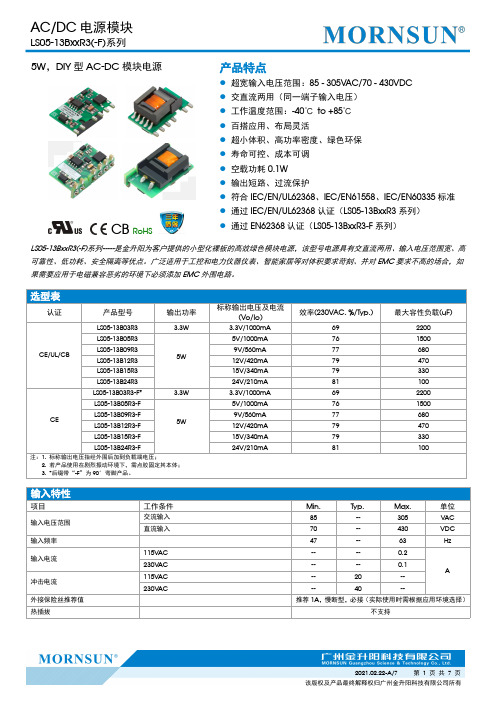
5W,DIY型AC-DC模块电源CB RoHS产品特点●超宽输入电压范围:85-305VAC/70-430VDC ●交直流两用(同一端子输入电压)●工作温度范围:-40℃to +85℃●百搭应用、布局灵活●超小体积、高功率密度、绿色环保●寿命可控、成本可调●空载功耗0.1W ●输出短路、过流保护●符合IEC/EN/UL62368、IEC/EN61558、IEC/EN60335标准●通过IEC/EN/UL62368认证(LS05-13BxxR3系列)●通过EN62368认证(LS05-13BxxR3-F 系列)LS05-13BxxR3(-F)系列-----是金升阳为客户提供的小型化裸板的高效绿色模块电源,该型号电源具有交直流两用、输入电压范围宽、高可靠性、低功耗、安全隔离等优点。
广泛适用于工控和电力仪器仪表、智能家居等对体积要求苛刻、并对EMC 要求不高的场合,如果需要应用于电磁兼容恶劣的环境下必须添加EMC 外围电路。
输入特性项目工作条件Min.Typ.Max.单位输入电压范围交流输入85--305VAC 直流输入70--430VDC 输入频率47--63Hz输入电流115V AC ----0.2A230V AC ----0.1冲击电流115V AC --20--230V AC--40--外接保险丝推荐值推荐1A ,慢断型,必接(实际使用时需根据应用环境选择)热插拔不支持选型表认证产品型号输出功率标称输出电压及电流(Vo/Io)效率(230VAC,%/Typ.)最大容性负载(uF)CE/UL/CBLS05-13B03R3 3.3W3.3V/1000mA 692200LS05-13B05R35W5V/1000mA 761500LS05-13B09R39V/560mA 77680LS05-13B12R312V/420mA 79470LS05-13B15R315V/340mA 79330LS05-13B24R324V/210mA81100CELS05-13B03R3-F* 3.3W 3.3V/1000mA 692200LS05-13B05R3-F5W5V/1000mA 761500LS05-13B09R3-F 9V/560mA 77680LS05-13B12R3-F 12V/420mA 79470LS05-13B15R3-F 15V/340mA 79330LS05-13B24R3-F24V/210mA81100注:1.标称输出电压指经外围后加到负载端电压;2.若产品使用在剧烈振动环境下,需点胶固定其本体;3.*后缀带“-F ”为90°弯脚产品。
SMC Thermo-chiller HRR系列操作手册说明书
HRX-OM-Y057Monitoring software for Thermo-chillersHRR series© 2020 SMC CORPORATION All Rights ReservedTo the usersThank you for purchasing SMC’s Thermo chiller (hereinafter referred to as the “product”).For safety and long life of the product, be sure to read this operation manual (hereinafter referred to as the “manual”) and clearly understand the contents.●Be sure to read and follow all instructions noted with “Warning” or “Caution” in this manual.●This manual is intended to explain the installation and operation of the product. Only people whounderstand the basic operation of the product through this manual or who perform installation and operation of or have basic knowledge about industrial machines are allowed to work on the product.●This manual and other documents attached to the product do not constitute a contract, and will notaffect any existing agreements or commitments.●It is strictly prohibited to copy this manual entirely or partially for the use by a third party without priorpermission from SMC.HRX-OM-Y057Table of contents Table of contentsIndemnification (1)Indemnification (1)Chapter 1Information on using the operating instructions (2)Chapter 2Introduction (2)Chapter 3System requirements (2)Chapter 4Installation (3)4.1Device driver (3)4.1.1Windows 7 (3)4.1.2Windows 10 (3)4.2Monitoring software (3)Chapter 5Connecting the thermo-chiller to a PC (3)Chapter 6Starting the monitoring software (4)Chapter 7Establishing a connection between the monitoring software and the thermo-chiller (4)Chapter 8Operation (5)8.1Main window (5)8.1.1Overview (5)8.1.2Control bar (6)8.1.3Navigation bar (7)8.1.4Process values (8)8.1.5Product information (8)8.1.6Display area (8)8.1.7Status bar (9)8.2Monitoring (9)8.2.1Live data (9)8.2.2Data history (10)8.3Diagram (11)8.4Settings (11)8.4.1Standard settings (12)8.4.2Alarm settings (12)8.4.3Communication settings (12)8.5Maintenance (12)8.6Alarms (13)8.7Communication (14)HRR SeriesHRX-OM-Y057Table of contents8.8Specifications (14)8.9Info (14)8.10Language (15)8.11Messages (15)8.11.1General messages (15)8.11.2Important messages (16)8.11.3Confirmation messages (16)HRR SeriesHRX-OM-Y0570 Indemnification1-1IndemnificationIndemnificationMonitoring software for Thermo-chiller HRR series(hereinafter referred to as “this software”),the “Indemnification” below will be applied. Read and accept them before using the product.This agreement comes into effect when the user installs this software to a computer.The user cannot install, use or copy this software unless they agree to this agreement.License Agreement1. The product is provided for use in manufacturing industries.The product herein described is basically provided for peaceful use in manufacturing industries.If considering using the product in other industries, consult SMC beforehand and exchange specifications or a contract if necessary. If anything is unclear, contact your nearest sales branch.Article 1 (Consent)1. This software is to be used in accordance with this Agreement non –exclusively for thelimited purpose of used for SMC Thermo-chiller HRR series.2. This software can be installed and saved on a PC for the sole purpose specified in thepreceding paragraph. Article 2 (Restrictions)1. This software is not to be copied except as specified in Article 1-2.2. This software license is not to be transferred or lent wholly or in part to a third party,whetherfor payment or free of charge.3. Modification, translation, adaptation or reverse engineering and recompiling of this softwareis not permitted. Article 3 (Precautions)1. When using this software, please read the operation manual and the operation manual attached to the thermo-chiller.2. This Software or the equipment contained in are subject to change without prior notice. Article 4 (Exemption of liability)SMC is not responsible for any damage incurred in the use of Software.Article 5 (Termination)1. If there is any breach of this Agreement, or when SMC decides to terminate thisAgreement, it will be terminated. 2. When this Agreement is terminated, please destroy this Software and any copies. Article 6 (Rights of this Software)The copyright and any other rights of this Software are owned by SMC, and protected by Japanese copyright laws and international treaty provisions.HRX-OM-Y057Chapter 1 Information on using the operating instructions1-2Chapter 1 Information on using the operating instructionsUsing the instructionsThese instructions enable the safe and efficient handling of the monitoring software for thermo-chillers (HRR series). The instructions are part of the software and must be stored so that they are easily accessible to personnel at all times.The personnel must carefully read through and understand these instructions before starting all activities. Compliance with all the handling instructions is required to ensure safe operation.Illustrations in these instructions are intended to provide a basic understanding and may differ from the actual design.Chapter 2 IntroductionThese operating instructions describe the set-up and functions of the monitoring software (hereinafter referred to as the Software) for thermo-chillers made by SMC corporation.The software enables users to adjust settings, start and stop thethermo-chiller and analyze and store process values. The software also helps users detect and rectify faults.Chapter 3 System requirements⏹ Windows: 7 or 10⏹ Net Framework: Version 3.5 or higher ⏹ RAM:min. 1 GB ⏹ Monitor resolution:min. 1366 x 768 *Note 1⏹Thermo-chiller firmware version:*Note 2● HRR012 - ## - 10 1.3 or higher ● HRR018 - ## - 10 1.3 or higher ● HRR010 - ## - 20 1.2 or higher ● HRR012 - ## - 20 2.3 or higher ● HRR018 - ## - 20 2.3 or higher ● HRR024 - ## - 20 2.3 or higher ● HRR030 - ## - 20 2.3 or higher ●HRR050 - ## - 201.1 or higher*Note 1) If using other monitor resolution, some character and figures may be cut.*Note 2) If HRR has uncomfortable firmware version, this monitoring software may not workcorrectly.HRX-OM-Y057Chapter 4 Installation Chapter 4 Installation4.1 Device driver4.1.1 Windows 7A device driver is required in order to connect thermo-chillers to a PC runningthe Windows 7 operating system. The PC will not detect the thermo-chillerwithout it.4.1.2 Windows 10No device driver is needed to connect thermo-chillers to a PC running theWindows 10 operating system. The thermo-chiller is supported by a standarddriver under Windows 104.2 Monitoring softwareThe software does not have to be installed. The .exe file merely has to becopied to the designated folder and can be started from there. Chapter 5 Connecting the thermo-chillerto a PCThe thermo-chiller has a USB type B port on the front. To connect thethermo-chiller to a PC, remove the cover cap that protects thethermo-chiller’s USB port and plug in a USB cable.A USB cable is not included with the thermo-chiller. It has to be provided bythe user.HRR Series 4.1 Device driver1-3HRX-OM-Y057Chapter 6 Starting the monitoring software4.2 Monitoring softwareHRR Series1-4Chapter 6 Starting the monitoring softwareOnce the software has been started by double-clicking the .exe file , the start screen opens. The software checks whether a thermo-chiller is attached. If so, it establishes a connection.A start button appears regardless of whether a thermo-chiller was found. Pressing the start button opens the software (Fig. 1).Fig. 1 Start screenChapter 7 Establishing a connection between the monitoring software and the thermo-chillerIf a thermo-chiller was detected when the software was started, the connection is established automatically. If multiple thermo-chillers are connected, a connection is established with the first thermo-chiller that detected. If no thermo-chiller was found automatically, a connection to the software can be established manually (see 8.1.2.5).HRX-OM-Y057 Chapter 8 OperationHRR Series 8.1 Main window1-5Chapter 8 Operation8.1 Main windowThe main window consists of multiple areas, which are described in detail in this section.8.1.1 OverviewFig. 2 Main window1. Control bar (see 8.1.2)2. Navigation bar (see 8.1.3)3. Process values (see 8.1.4)4. Product information (see 8.1.5)5. Display area (see 8.1.6)6. Status bar (see 8.1.7)12536HRX-OM-Y057Chapter 8 Operation8.1 Main windowHRR Series1-68.1.2 Control barThe connection to a thermo-chiller can be controlled via the control bar. The thermo-chiller can also be started and stopped via this bar.Fig. 3 Control barMoving the mouse pointer over the control bar causes it to extend (see Fig. 3).8.1.2.1Thermo-chiller on/offThis button can be used to start and stop the thermo-chiller. This is only possible if Control mode is activated.8.1.2.2Control modeActivating Control mode enables the user to start and stop the thermo-chiller and transfer settings. When Control mode is deactivated, all the control buttons that cannot be used in this case are disabled.8.1.2.3MessagesA message box appears when this button is pressed. All the messages that have been generated since the software was started can be reread here.8.1.2.4Auto connectThis function is used to establish a connection between the software and a thermo-chiller. When the button is pressed, the COM ports are queried one by one. A connection is established as soon as a thermo-chiller responds. This function is disabled when a thermo-chiller is connected. To select a different thermo-chiller that is connected to the PC, the ‘Manual connect’ function must be used (see 8.1.2.5).HRR Series 8.1 Main window1-78.1.2.5 Manual connectBecause ‘Auto connect’ always connects t o the first thermo-chiller on the COM port list, the ‘Manual connect’ button can be used to connect thesoftware to a different thermo-chiller that is connected to the PC. To this end, the corresponding COM port must be selected via the ‘COM port’ button (see 8.1.2.8). The connection is terminated to the currently connectedthermo-chiller and a connection is established to the selected thermo-chiller.8.1.2.6RefreshThis button refreshes the COM port list (see 8.1.2.8). This is necessary if a thermo-chiller is connected when the software is already open.8.1.2.7DisconnectThe ‘Disconnect’ button terminates the connection between the software and the connected thermo-chiller.8.1.2.8 COM portThe ‘COM port list’ shows all COM port devices which are connected to the PC. When more than one chiller is connected, it is possible to select the one which should be displayed on the software.8.1.3 Navigation barThe navigation bar enables the user to change the contents of the display area (see 8.1.6) and set the language for the software.Fig. 4 Navigation bar⏹ Monitoring (see 8.2)⏹ Chart (see 8.3)⏹ Settings (see 8.4)⏹ Maintenance (see 8.5)⏹ Alarm (see 8.6)⏹ Communication (see 8.7)⏹ Specification (see 8.8)⏹ Info (see 8.9)⏹ Language (see 8.10)8.1 Main windowHRR Series1-88.1.4 Process valuesThe most important process values are displayed in the chart in the lower area of the software. Depending on the thermo-chiller, this area may also display the electrical conductivity of the circulating fluid, in addition to the return temperature, pressure and flow rate (Fig. 5).Fig. 5 Process values8.1.5 Product informationThis area displays the product key, the serial number and the version of the firmware installed on the connected thermo-chiller (Fig. 6).Fig. 6 Product information8.1.6 Display areaThe display area displays the software content that is currently selected on the navigation bar (see 8.1.3).Fig. 7 Display area8.1.7 Status barThe most important status messages are displayed in the display area asgreen or red buttons (Fig. 8).Fig. 8 Status barRun/Stop: Green = Device in operation Red = Device in standbyAlarm status: Green = No alarm Red = Alarm activeComm. status Green = Communication active Red = No communicationControl status Green = Control mode activated Red = Control mode deactivated Remote status Green = Remote activated Red = Remote deactivated8.2 MonitoringThe monitoring menu provides a visual representation of the most importantprocess data. The process data from the past 24 hours can be viewed in the‘Live data’ window, while all the process data since recording began can beviewed in the ‘Historic data’ window.8.2.1 Live dataThe ‘Live data’ window enables the user to view process data from the past24 hours since the software was started or the live data of the thermo-chillerwas reset. The data can also be saved to a file. In addition, the user canchange the set temperature of the thermo-chiller.4 122Fig. 9 Monitoring / Live dataHRR Series 8.2 Monitoring1-91. If Control mode is activated, the user can apply the set temperature in the input field by pressing the‘Set’ button. The ‘Save’ button saves the process data to a file. ‘Reset’ deletes the previous process data.2. The Y-axes can be adjusted via the input fields and buttons.3. The displayed time window level can be set to between 2 minutes and 24 hours.4. Clicking the corresponding symbol in the ‘Graph selection’ area enables the user to select whichprocess data should be displayed on the graphs and which should be hidden.8.2.2 Data historyThe ‘Static data’ window is used to display all the process data since thesoftware started recording. Clicking the ‘Reset’ button in the ‘Live data’window (see 8.2.1) also deletes the data in ‘Static data’.12Fig. 10 Monitoring / Data history8.2 Monitoring HRR Series 1-10HRR Series 8.3 Diagram1-118.3 DiagramThe diagram visualizes the internal structure of the thermo-chiller. Relevant process values such as temperatures, pressures, durations, etc. aredisplayed here. The diagram differs depending on which thermo-chiller is connected. The software distinguishes between the following types of devices: Air-cooled, water-cooled, with DI control and without DI controlFig. 11 Diagram8.4 SettingsIn this area, the user can view, change and transfer all thermo-chiller settings and save the settings to a file. The contents of the various settings windows (see 8.4.1 to 8.4.3) are based on the operating instructions for the thermo-chillers.Fig. 12 Setting menuThe buttons in the upper right-corner enable the user to import the current settings of the thermo-chiller or export the settings that were adjusted by the software. The settings can also be exported to or importedfrom a file on the PC, and the thermo-chiller can be reset to factory settings.8.5 MaintenanceHRR Series1-128.4.1 Standard settingsAll the standard settings can be adjusted via this menu. All the settings are described in the operating instructions for the thermo-chillers. Settings that are not supported for the current device are greyed out.8.4.2 Alarm settingsAll the alarm settings can be adjusted via this menu. All the settings are described in the operating instructions for the thermo-chillers. Settings that are not supported for the current device are greyed out.8.4.3 Communication settingsAll the communication settings can be adjusted via this menu. All the settings are described in the operating instructions for the thermo-controllers. Settings that are not supported for the current device are greyed out.8.5 MaintenanceFor preventive maintenance, certain components of the thermo-chillers have operating hour counters. They can be viewed in the maintenance area.Fig. 13 Maintenance menuThere are fixed, recommended maintenance intervals for the fans, pumps and compressors. The time intervals for the dust filters (air-cooled thermo-chillers only) and DI filters (thermo-chillers with DM option only) can be adjusted via the settings (see 8.4.1) depending on the operating conditions. Operating hour counters that are unnecessary for the current device are hidden.The counters can be reset individually via the thermo-chiller display.8.6 AlarmsThermo-chillers feature a variety of alarms. When one or more alarms aretriggered, they can be analyz ed in greater detail in the ‘Alarms’ area. It is alsopossible to download and analyze the last 150 alarms from thethermo-chiller’s alarm memory. In addition to the process data at the time thealarm occurred, the user also receives an alarm description with possiblecauses and a troubleshooting suggestion.12Fig. 14 Alarms menu1. The three buttons enable the user to download the desired alarms from the thermo-chiller. The topbutton loads all current alarms, the middle one the alarm history of the last 20 alarms and the bottom one the alarm history of the last 150 alarms.2. Once the alarms have been loaded successfully, the user can view the alarm description for eachalarm as well as the process data at the time the alarm occurred. To do so, the user must select the desired alarm using the button.HRR Series 8.6 Alarms1-138.7 CommunicationHRR Series1-148.7 CommunicationThe communication area displays all the telegrams that are exchanged between the thermo-chiller and the customer application. It also displays information regarding faulty telegrams or communication problems.Fig. 15 Communication window1. Actual communication settings of the chiller.2. Current communication status3. Last transmitted and received string4.History of transmitted and received messages8.8 SpecificationsThe Specifications page displays the following characteristics of the thermo-chiller: ⏹ Cooling power (50/60 Hz) ⏹ Heating power (50/60 Hz)⏹Pump characteristics (pressure/flow rate)The software displays the appropriate characteristics for the current device type.8.9 InfoThe information area contains the legal notice and the legal provisions that are relevant to this software.1234HRR Series 8.10 Language1-158.10 LanguageWhen the software is started, the computer’s system language is used as the interface language. If the user wants to select another language, they can select it via the ‘Language’ drop -down menu. The following languages are available:⏹ English ⏹ Japanese ⏹ Spanish ⏹ Italian ⏹ Deutsch ⏹ Chinese ⏹ French ⏹ Russian ⏹ Turkish ⏹Korean8.11 Messages8.11.1 General messagesFor certain events, information is displayed on the left side of the screen and then automatically hidden. This information is shown when, for example, a command such as ‘Reset to factory settings’ is successfully executed.Fig. 16 General message8.11 MessagesHRR Series1-168.11.2 Important messagesImportant messages contain information such as triggered alarms that have a major influence on the software or the thermo-chiller. These messages must be actively acknowledged so that they can be hidden again.Fig. 17 Important message8.11.3 Confirmation messagesCertain interactions require confirmation from the user to prevent inadvertent changes to the software or the thermo-chiller.Fig. 18 Confirmation messageNote: Specifications are subject to change without prior notice and any obligation on the part of the manufacturer. © 2020 SMC Corporation All Rights Reserved。
Y、YKS系列高压三相异步电动机产品样本
电动机额定电压有6kV、10kV两种,电源的额定频率为50Hz。
4.绝缘等级及温升限值
电动机的绝缘等级为F级。
5.轴承结构形式及温度限值
轴承结构有滚动轴承和滑动轴承结构,具体采用何种结构形式,详见外形及安装尺寸数据表,滑动轴承结构正常产品为强制润滑,也可根据需要制成自润滑。
6.防护等级
防护等级: IP54
旋转方向:顺时针
使用环境:户内
进线方式:橡套
海拔高度:≦1000m
环境温度:-15℃~40℃
3.有附加要求的订货
若对下列诸项中的一面或多项有要求时,须在订货时申明
3.1.电压不是6kV及10kV,如3.3kV、6值;或者功率与安装尺寸的对应关系与数据表不同;
GB/T 1993-1993旋转电机冷却方法(eqv IEC60034-6:1991
GB/T 4772.2-1999旋转电机尺寸和输出功率等级第2部分:机座号355-1000和凸缘号1180-2360 (idt IEC 60072-2:1990
GB/T 4942.1-2006旋转电机整体结构的防护等级(IP代码分级(idt IEC60034-5:2000
热带型,有气候防护场所(T ;热带型,无气候防护场所(WT ;
户外防轻腐蚀型(W ;
户外防中等腐蚀型(WF1 ;
户外防强腐蚀型(WF2 ;
户内防中等腐蚀型(F1 ;
户内防强等腐蚀型(F2 ;
上述防护类型标注于电动机型号的最后面,例如:YKS500-2WF1。
9.接线方式
Y形接法。
10.电缆引入装置
电机正常情况下提供橡套电缆装置,可根据用户需要提供钢管布线装置或铠装电缆装置。
0EE.138.170-2007
Fitness Madness 19ASSEMBLY INSTRUCTIONS说明书

5740AH - 40 Ton Air/Hydraulic Shop Press 5750AH - 50 Ton Air/Hydraulic Shop PressCONTENTS:Page 1Specifications2Safety Information and Warranty Information 3Parts List4-6Assembly Instructions789Pump and Ram Assembly Instructions Procedure for Bleeding Air Pump Instructions10-11Winch Kit Parts List and Winch Installation Instructions 12Replacement Parts List© Copyright 2020, Sunex Tools ®SAFETY INFORMATIONThis symbol alerts you to the possibility of serious injury or death if instructions are not followed.This symbol alerts you to the possibility of damage to or destruction of equipment if instructions are not followed.Failure to heed these warnings may result in lossof load, damage to the press and/or failure resulting in property damage, personal or fatal injury. Thisoperating manual contains important details concern-ing the safe operation of this tool. The user must read and understand these details before any use of the tool. This manual must be retained for future reference.• Read, study, understand and follow all instructions before operating this press.• Always wear safety goggles, (users and bystanders).•Parts being pressed may splinter, shatter, or be ejected from the press at a dangerous rate of speed. Because there are a variety of press applications, it is the responsibility of the press owner to provide adequate guards, eye protection and protective clothing to the press operator.• Visual inspection of the press should be made before use, checking for signs of cracked welds, bent bed pins, loose or missing bolts, leaks, or any other structural damage. Corrections must be made before using the press.•Do not go near leaks. High pressure hydraulic uid can puncture skin and cause serious injury,gangrene, or death. If injured, seek emergency medical help as immediate surgery is required to remove the uid.• Prior to use make sure the press is securely anchored to a concrete oor.•Keep hands, arms, feet, and legs out of work area. Accidental slippage can result in personal injury.• Always use an accurate force gauge to measure pressing force.• Do not exceed the rated capacity or tamper with the pressure/force settings. When attachments and adapters are used the rated capacity of the system shall be no greater than the rated capacity of the lowest rated component or combination of components that make up the system. • Avoid off-center loads. Offset loads can damage ram and may cause load to eject at a dangerous rate of speed. Do not use any spacer or extender between the press ram plunger and the item being pressed. If there is not enough ram stroke, adjust the height of the movable bolster.•Remove all loads from movable bolster before attempting to adjust bolster height. Beware of possible falling bolster.•Press only on loads supported by movable bolster and press plates included. Do not support loads on oor or press frame legs.• When using any accessories such as press plates or arbor plates, be certain they are centered on the movable bolster and in full contact with both sides of the bolster.• Before applying load, be certain all movable bolster supporting pins are fully engaged. Verify lift cables (if equipped) are slack before pressing on the bolster.• Always use a bearing shield when pressing bearings.•Use caution when positioning work to be pressed to ensure the item to be pressed cannot be ejected at a dangerous rate of speed.• Release hydraulic pressure before loosening any ttings.• Maintain proper hydraulic uid levels.• Do not make any alterations or modi cations to the press.•This product may contain one or more chemicals known to the State of California to cause cancer and birth defects or other reproductive harm. Wash hands thoroughly after handling.•Failure to heed and understand these markings may result in serious or fatal personal injury and/or property damage.OWNER/USER RESPONSIBILITYThe owner and/or user must have an understanding of the manufacturer'soperating instructions and warnings before using this press. Personnel involvedin the use and operation of equipment shall be careful, competent, trained,and quali ed in the safe operation of the equipment and its proper use whenservicing motor vehicles and their components. Warning information shouldbe emphasized and understood.If the operator is not uent in English, the manufacturer's instructions andwarnings shall be read to and discussed with the operator in the operator'snative language by the purchaser/owner, making sure that the operatorcomprehends its contents.Owner and/or user must study and maintain for future reference the manufactur-er’s instructions. Owner and/or user is responsible for keeping all warning labels and instruction manuals legible and intact. Replacement labels and literature are available from the manufacturers.INSPECTIONVisual inspection of the shop press should be made before each use of the press, checking for damaged, loose or missing parts. Each press must be inspected by a manufacturer’s repair facility immediately, if subjected to an abnormal load or shock. Any press which appears to be damaged in any way, is found to be badly worn, or operates abnormally must be removed fromservice until necessary repairs are made by a manufacturers's authorized repair facility. It is recommended that an annual inspection of the press be made by a manufacturer’s authorized repair facility and that any defective parts, decals or warning labels be replaced with manufacturer’s speci ed parts. A list of authorized repair facilities is available from the manufacturer.SAFETY INSTRUCTIONS•CHECK YOUR LOCAL, STATE AND FEDERAL REGULATIONSREGARDING THE SAFE USE OF THIS EQUIPMENT.•Your safety is top priority. Please handle equipment with care.•Fully retract unit and remove all items from the press bed frame.•Support the press bed, and remove the pins.•Raise or lower bed to desired height and reinstall press pins. Be certainpins are fully engaged in the parallel anges of the upright columns.•Position press on a at, level, hard surface, preferably concrete.Make sure all nuts and bolts are tight.•Clear the area of bystanders, especially small children, before using.•Set the press bed to the required height. The press is most effectivewhen the work piece is located 1 inch below the ram’s retracted position.The compression stroke can include the entire 5 inch working range.•The press is designed to exert a force on anything which is positionedbeneath its ram. The work piece can pop out from under the ram at a high rate of speed and injure someone.•Pressing Bearings: It is essential that you use the bearing shield whenpressing bearings on or off.LIMITED WARRANTY:SUNEX INTERNATIONAL, INC. WARRANTS TO ITS CUSTOMERS THAT THE COMPANY’S SUNEX TOOLS ® BRANDED PRODUCTS ARE FREE FROM DEFECTS IN WORKMANSHIP AND MATERIALS.Sunex International, Inc. will repair or replace its Sunex T ools ® branded products which fail to give satisfactory service due to defective workmanship or materials, based upon the terms and conditions of the following described warranty plans attributed to that speci c product. This product carries a ONE-YEAR warranty. During this warranty period, Sunex T ools ® will repair or replace at our option any part or unit which proves to be defective in material or workmanship. Other important warranty information....This warranty does not cover damage to equipment or tools arising fromalteration, abuse, misuse, damage and does not cover any repairs or replace-ment made by anyone other than Sunex Tools ® or its authorized warranty service centers. The foregoing obligation is Sunex Tools ®’ sole liability under this or any implied warranty and under no circumstances shall we be liable for any incidental or consequential damages. Note: Some states do not allow the exclusion or limitation of incidental or consequential damages, so the abovelimitation or exclusion may not apply to you. Return equipment or parts to Sunex Tools ®, transportation prepaid. Be certain to include your name and address, evidence of the purchase date, and description of the suspected defect.If you have any questions about warranty service, please write to Sunex Tools ®.This warranty gives you speci c legal rights and you may also have other rightswhich vary from state to state. Repair kits and replacement parts are available for many of Sunex Tools ® products regardless of whether or not the product is still covered by a warranty plan.SHIPPING ADDRESS: MAILING ADDRESS:Sunex Tools Sunex Tools 315 Hawkins Rd. P .O. Box 4215Travelers Rest, South Carolina 29690 Greenville, South Carolina 29608THIS OPERATING MANUAL CONTAINS IMPORTANT SAFETY INFORMATION. READ CAREFULLY AND UNDERSTAND ALL INFORMATION BEFORE OPERATING THIS TOOL. SAVE THIS MANUAL FOR FUTURE USE.WARNING: This product can expose you to chemicals including nickel, which is known to the State of California to cause cancer and birth defects or other reproductive harm.For more information go to .Press Frame - 1Press Bed - 1Press Feet - 2Z Bar - 11/2"-13 x 1-1/2" Hex Head Bolts - 101/2" Nuts - 10Air MotorPump and Ram - 1Pump Extension Handle - 11" x 3" x 14"Press Plates - 2Accessory only -Not needed for assemblyPushing Adapter - 1Accessory only -Not needed for assemblyBearing Shield - 1Accessory only -Not needed for assemblyESTIMATED ASSEMBLY TIME: 30 MINUTESACCESSORIESASSEMBL CONTINUEDPUMP AND RAM ASSEMBL Y INSTRUCTIONSPROCEDURE FOR BLEEDING AIRPUMP INSTRUCTIONSWINCH INSTALLATION INSTRUCTIONS CONTINUED。
哈希公司水质监测仪器说明书

哈希公司成立于1947年,现为美国丹纳赫集团一级子公司,总部设在美国科罗拉多州的拉夫兰市,是设计和制造水质、水文监测仪器的专业厂家。
工厂分别分布于美国、瑞士、德国、法国和英国。
作为水质、水文监测仪器的世界领导者,哈希公司产品被全球用户广泛应用于饮用水、地下水、地表水、市政污水、工业污水、半导体超纯水、制药/电力及其他工业净水、等领域,其全线产品系列涵盖实验室定性/定量分析、现场分析、流动分析测试、在线分析测试。
产品具有测量精确、运行可靠、操作简单、低维护量,结构紧凑等特点。
哈希公司一直致力于使水质分析过程更方便、更迅捷、更可靠:各类包装的即开即用型化学试剂包,不仅为精确的化学分析提供了可靠的质量保障,也为用户节约了宝贵的时间和人力资源,成为了中国环境现场应急监测的首选工具;各种类型的在线水质分析仪器,以其准确度高、维护量小、可测量的水质参数多等特点,可以满足污水处理厂、饮用水厂、工业过程水处理、工业污染源、水质自动监测站等不同场合的应用。
哈希公司的水质分析仪器产品在中国已经有超过20年的成功应用, 哈希在线水质分析仪器在中国水处理市场以及全球范围内都得到了广泛的应用,一直以来哈希在线浊度分析仪都是饮用水行业关键性运行指标-浊度测试的常用仪器。
我们的目标是继续为广大用户提供可靠的仪器、测试方法、简单的操作步骤和优质的客户服务,不断地提高产品的质量以满足客户需求不断变化的需要。
目前公司已经在北京、上海、广州和重庆、沈阳、西安、武汉、济南、南京、福州设立了办事处,为中国的广大客户提供方便、周到的服务。
目录水位监测 (2)流量监测 (12)雨量监测 (29)气象监测 (31)水质监测 (33)典型应用 (60)基本介绍用于连续测量水位的精巧型气泡水位计。
它具有高量程、高精度的特点,并带有4-20 mA 模拟输出和SDI12标准接口,最新设计的智能型气泵可以在满足测量精度的前提下减小打气体积,以便节省系统功耗。
水泵站低压配电图纸设计
空调项目报价模板
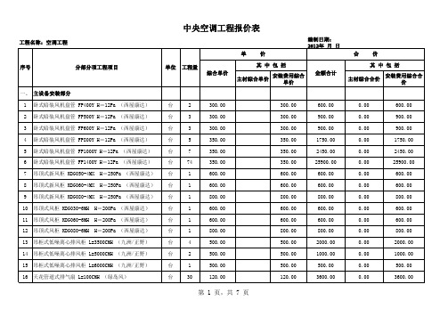
17 天花管道式排气扇 L=200CMH (绿岛风) A 设备小计:
台
88
120.00
二、 水系统安装 1 2 3 4 5 6 7 8 9 热镀锌钢管 DN20×2.75mm (华歧/南粤) 热镀锌钢管 DN40×3.5mm (华歧/南粤) 热镀锌钢管 DN50×3.5mm (华歧/南粤) 热镀锌钢管 DN65×3.5mm (华歧/南粤) 热镀锌钢管 DN80×3.75mm (华歧/南粤) 热镀锌钢管 DN100×3.75mm (华歧/南粤) 橡塑发泡保温套管φ =28mm δ ≥25mm (华美/致胜) 橡塑发泡保温套管φ =48mm δ ≥25mm (华美/致胜) 橡塑发泡保温套管φ =60mm δ ≥30mm (华美/致胜) 10M 10M 10M 10M 10M 10M 10M 10M 10M 10M 10M 10M 个 55 51 23.2 28 25 33 55 51 23.2 28 25 33 188 420.00 630.00 700.00 750.00 850.00 1050.00 100.00 130.00 175.00 185.00 215.00 240.00 75.00 120.00 280.00 350.00 400.00 500.00 650.00 70.00 100.00 145.00 155.00 185.00 200.00 45.00 300.00 350.00 350.00 350.00 350.00 400.00 30.00 30.00 30.00 30.00 30.00 40.00 30.00 23100.00 32130.00 16240.00 21000.00 21250.00 34650.00 5500.00 6630.00 4060.00 5180.00 5375.00 7920.00 14100.00 6600.00 14280.00 8120.00 11200.00 12500.00 21450.00 3850.00 5100.00 3364.00 4340.00 4625.00 6600.00 8460.00 16500.00 17850.00 8120.00 9800.00 8750.00 13200.00 1650.00 1530.00 696.00 840.00 750.00 1320.00 5640.00
XL6006 180KHz 60V 5A开关电流升压型LED恒流驱动器说明书
180KHz 60V 5A 开关电流升压型LED恒流驱动器XL6006特点⏹5V到32V宽输入电压范围⏹输出电压最高可升压至60V⏹0.22V输出电流采样电压⏹输入电压24V,输出可驱动16串1W/3WLED灯⏹固定180KHz开关频率⏹最大5A开关电流⏹94%以上转换效率⏹出色的线性与负载调整率⏹EN脚TTL关机功能⏹内置功率MOS⏹内置软启动功能⏹内置频率补偿功能⏹内置热关断功能⏹内置限流功能⏹TO263-5L封装应用⏹通用LED照明⏹升压恒流驱动⏹显示器LED背光描述XL6006是一款升压恒流型LED驱动器,具有出色的线性调整率与负载调整率,可以驱动1W/3W/5W的LED灯。
XL6006内置固定频率振荡器与频率补偿电路,简化了电路设计。
当输入电压等于24V时,XL6006可驱动16串1W/3W LED。
PWM控制环路可以调节占空比从0~90%之间线性变化。
内置使能功能、过电流保护功能。
内部补偿模块可以减少外围元器件数量。
图1.XL6006封装180KHz 60V 5A 开关电流升压型LED 恒流驱动器 XL6006引脚配置FB SW EN GNDVIN 12345TO263-5L图2. XL6006引脚配置表1.引脚说明引脚号 引脚名称 描述1 GND 接地引脚。
2 EN 使能引脚,低电平关机,高电平工作,悬空时为高电平。
3 SW 功率开关输出引脚,SW 是输出功率的开关节点。
4 VIN 电源输入引脚,支持DC5V~32V 宽范围电压操作,需要在VIN 与GND 之间并联电解电容以消除噪声。
5 FB反馈引脚,参考电压为0.22V 。
180KHz 60V 5A 开关电流升压型LED 恒流驱动器 XL6006方框图NDMOSVINSWGNDFB2.5V 0.22VCOMP2.5V Regulator 0.22V ReferencePhase CompensationRS LatchUVLOSoft StartThermal ShutdownEAEA ∑Driver OCPOVPENOscillator180KHzSlop Compensation图3. XL6006方框图典型应用XL6006CIN 47uF 35VL1 47uh/5AVIN41253GNDVINSWFBENONOFFI LED =0.22/RSD1 SS38RS 350mASeries 16 1W LEDC1 105COUT 100uF 63VC2 105图4. XL6006典型应用电路180KHz 60V 5A开关电流升压型LED恒流驱动器XL6006订购信息产品型号打印名称封装方式环保认证包装类型XL6006E1 XL6006E1 TO263-5L RoHS & HF 800只每卷绝对最大额定值(注1)参数符号值单位输入电压Vin -0.3到36 V-0.3到Vin V 反馈引脚电压VFB使能引脚电压V-0.3到Vin VEN-0.3到60 V 输出开关引脚电压VSW内部限制mW 功耗PD热阻(TO263-5L)R JA30 o C /W (结到环境,无外部散热片)操作结温T-40到125 o CJ-65到150 o C 贮存温度范围TSTG引脚温度(焊接10秒) T260 o CLEADESD (人体模型) 2000 V 作,在绝对最大额定值条件下长时间工作可能会影响芯片的寿命。
Parker Hannifin Corporation 电子方向控制阀门目录说明书

Series D*FXGeneral DescriptionSeries D*FX proportional directional control valvesare direct operated solenoid valves with electronicspool position feedback, and on-board integratedcontrol electronics. D*FX valves are user configurableto proportionally control flow in response to voltage orcurrent command signals. Valves are available in sizesNG6 (CETOP 3) and NG10 (CETOP 5).Three electronic control options are available sim-plifying user application. Configurations include theindustrial standard 7-pin interface, or options for a userconfigurable simple proportional analog outer closedloop, or ± 10V reference outputs which can be used asuser command voltage references.D*FX valve performance is characterized by highresolution flow control, repeatability, and good dynamicperformance. T ypical applications include precise andreproducible control of actuator speed in rapid/slowspeed profiling, and smooth acceleration and decelera-tion performance.Features•Integrated valve electronics.•Versatile electronic control options.•Spool position feedback.Technical Information•Spring centered spool.•Manual override.•Progressive flow characteristics for high resolution flowrate adjustment for small commands.•LED functional diagnostics.SpecificationsInterface DIN NG6 (CETOP 3) NG10 (CETOP 5)Flow Rating @10 Bar (150 PSI) ∆p (P→A, B→T)(spool options up to)1)LPM (GPM) 20 (5.3) 60 (15.9) Maximum Flow LPM (GPM) 47 (12.5) 170 (45)Step Response (time to reach 90% of a 100% step command) ms 60 75Hysteresis % <1.5Repeatability% <0.5Max. Operating PressurePort P, A, B Bar (PSI) 315 (4500)PortT 35 (500)Fluid Cleanliness Level ISO Class 18/16/13Fluid Viscosity, Recommended 75 – 600 SSUFluid Temperature, 0°C to +60°CRecommended (+32°F to +140°F)Ambient Operating -20°C to +60°CTemperature (-4°F to +140°F)Electrical Power Requirements24V Version ‘J’: NG6 (03) 18 to 30 VDC, 3A24V Version ‘J’: NG10 (05) 18 to 30 VDC, 4A12V Version ‘K’: NG06 (03) only 11.5 to 15 VDC, 4ACommand Signal (impedance)(select by ordering code)24V Version ‘J’ 0 ± 10 VDC (100K ohm)0 ± 20 mA (499 ohm)Command Polarity Pin ‘D’ more positivethan ‘E’; Flow P to ASpool Position Monitor24V Version ‘J’ 0 ± 10 VDC12V Version ‘K’ 0 ± 5 VDCVoltage References: Not a powered outputOnly for 10K Ohm potsMating Connector Not a powered outputOnly for 10K Ohm pots7-Pin CEfor Electronic Design ‘B’ Part #50040726-Pinfor Electronic Design ‘C’ & ‘D’ Part #697561Environmental Protection Class NEMA 4 (IP65)1) Actual pressure drop required for each metering land, up to the specified maximum flow rate is:Q actualQ rated[or] = (75) ()2PSI; (Q in GPM)Q actualQ rated∆P actual = (5) ()2Bar; (Q in LPM)Flow rate for different ∆p per control edge: Qx= QNom.· ∆p x∆p Nom.Series D*FXOrdering Information3.4 kg (7.5 lbs.)8.3 kg (18.3 lbs.)** Spool type E01 only.Mounting InterfaceRefer to Mounting Interface Dimensions in the Proportional Directional Valve section of this catalog.AccessoriesRefer to the Accessories section for bolt kits, subplates, connectors and pre-assembled cable assemblies.Design Series NOTE: Not required when ordering.D*FXProportional Directional Spool TypeFlowStyleElectronic SealElectronic Supply Valve 0* Only available onD 1FXApplication GuidelinesD*FX proportional valves are available in three controlconfigurations. Option ‘B’ conforms to the industrialproportional valve standard and is interchangeablewith most competitors’ valves of this type. Options ‘C’and ‘D’ are designed to simplify user application byproviding specific features. Note that the ‘B’ controloption uses the industrial standard CE compliant 7-pinMS connector while options ‘C’ and ‘D’ use a 6-pin MSconnector. Refer to the table below for connector pin-out assignments.Specifications Electronic Design Option‘-B’ ‘-C’ ‘-D’Function Connector Pin AssignmentPower Supply +V A E E0V B D DReference +10V – A AOutputs -10V – F FEnable C – –Command +CMD D B B-CMD E – –Spool PositionMonitor F – COuter LoopFeedback – user – C –Protective Ground G – –Internal AdjustmentRefer to the Installation Guide for set-up, configuration,and application guidelines (packaged with each valve).D1FX: Installation Bulletin 2583-M1/USAD3FX: Installation Bulletin 2587-M1/USADesign ‘B’ Option — Industrial Standard 7-Pin MS Connector InterfaceElectronic design option ‘B’ implements the industrial standard 7-pin MS connector interface. The design provides a differential command input that is user configurable as voltage or current, an external valve enable feature, and a spool position monitor output. T o specify this option, refer to the Ordering Information page, Electronic Design block.EnableSpool Position Monitor(Note 2)Protective EarthSupply Voltage(Note 2)Note 1:Install jumper JP1 for current command input.Refer to Installation Bulletin 2583-M1/USA (D1FX).Note 2:Refer to specifications.Voltage orCurrent input(Note 1)+ CMD- CMD+V0V5 (30V)Red LEDP A®Green LEDP B®NullFactorySetGainBiasConfigurationJumpers (1-5)CalibrationSwitchMin.AMin.BMax.AMax.BTest Points1:Spool P2:Adj.CMD3:CommonDesign ‘C’ Option — User Configurable Analog Outer Closed LoopElectronic design option ‘C’ provides an additional analog closed outer loop function for user application. Thisfeature can be used to control simple position control loops where analog resolution and a single proportional gain control are adequate. The design provides a single ended command input that is user configurable as voltage or current, and an outer loop feedback sensor voltage input. ±10 volt outputs are available to reference the outer loop feedback sensor if required. To specify this option, refer to the Ordering Information page, Electronic Design block.Design ‘D’ Option — Single Ended, Bipolar Command Input, with ± Volt Reference OutputElectronic design option ‘D’ provides a single ended, bipolar command input that is user configurable as voltage or current. ±10 volt references are available for user supplied off-board command potentiometers. A spool position monitor output is also provided. T o specify this option, refer to the Ordering Information page, Electronic Design block.Voltage Input Current Input (Note 1)Outer Loop Feedback Input Note 1:Install jumper JP1 for current command input.Refer to Installation Bulletin 2583-M1/USA (D1FX).Note 2:Install jumper JP4 to invert user outer loop feedback input signal.ReferenceVoltage OutputsSupply VoltageF+10V -10V+24V 0V0...±10V 0...±20mA0...±10VSeries D*FXPerformance Curves9045AmplitudeRatio(dB)Phase Shift (°)Frequency(Hz)D1FX Frequency Responseat 10% Command, 50% Offset10203040506085634219045AmplitudeRatio(dB)Phase Shift (°)D3FX Frequency Responseat 10% Command, 50% Offset1020304050608563421Frequency(Hz)Shaded area: Actual flow subject to the system load dynamicsNote: 81 and 82 spools - decrease limits by 15%1)D3F Operating LimitsXat 100% CommandP A :B T;or P B :A T®®®®Flow(Q)BarPSIPressure Drop6910002071383000200027640001)1)Flow(Q)BarPSIPressure DropD1F Operating LimitsXat 100% CommandP A :B T;or P B :A T®®®®138692000100020730002764000020*********5Flow(Q)D1FX Flow Characteristicsat p = 5 Bar (72.5 PSI) per metering edgeP®®®®A :B T;or P B :A T020*********Flow(Q)D3FX Flow Characteristicsat p = 5 Bar (72.5 PSI) per metering edgeP A :B T;or P B :A T®®®®Series D*FXDimensions D1FXInch equivalents for millimeter dimensions are shown in (**)D3FXInch equivalents for millimeter dimensions are shown in (**)。
LS-1863A

目录
1
目录
前 言 ………………………………………………………………………………………………………….5 前言 ………………………………………………………………………………………………………….5 安全注意事项…………………………………………………………………………………………………..5 注意 ………………………………………………………………………………………………………….6 质保 ………………………………………………………………………………………………………….7 一般质保………………………………………………………………………………………………………..7
第 7 章 标准品误差修正预设值功能的操作............................................................................................ 51 7.1 标准品误差修正预设值的测试................................................................................................. 51 7.1.1 准备 ................................................................................................................................. 51 7.1.2 用键面操作进行标准品误差修正预设值的测试 ................................................................ 52 7.1.3 用外部信号输入方式进行标准品误差修正预设值的自动测试……………………………...53 7.2 标准品误差修正预设值测试时的合格与否判断以及异常检查 ................................................. 53
杆上变标准施工图(包含详细材料清单)

济南达科力华机械设备有限公司电动调节阀产品手册说明书

济南达科力华机械设备有限公司(第五版)(提示:请妥善保管,以备急需,遗失不补!)电动调节阀产品手册书中国·山东电话:0531-6869 0668济南达科力华机械设备有限公司主要从事供热节能方面的技术及产品开发;水处理等行业和领域的技术研发、设备制造和工程实施、方案设计、技术服务等工作。
包括西门子温控阀、西门子温控器西门子电动执行器等相关技术咨询、暖通及热能设备销售、安装与调试,西门子温控阀可实现无人值守,超温报警,温度补偿等人性化控制。
济南达科力华机械设备有限公司还是依托省农科院兴办的集科、工、贸于一体的科技型高新技术企业,在工厂化养殖自动化控制领域(食用菌、花卉等)、食品加工等与省农科院深度合作,在温度、湿度、气体浓度、压力等自动控制上取得良好的效果,得到广泛认可。
公司同时代理德国西门子楼宇科技产品,为暖通空调设备厂家及工程公司提供售前、售中和售后服务工作,为广大用户提供优良产品和优质服务。
公司秉承“诚信至上,以人为本,效率优先,服务社会”的办企原则,以优质的产品和高效的售后服务回报广大客户。
路漫漫其修远兮,吾将上下而求索。
孜孜耕、默默前行,是我们永远不变的敬业精神;自强不息,敢于亮剑是我们永远不变的创业精神。
电动温控阀,自力式温控阀,电动二通阀,电动三通阀电动调节阀,减温减压装置,电动减压阀,全自动软化水电动压差旁通阀,高频电子水处理,楼宇自控系统、工厂化养殖自控系统解决方案,工业生产温控、压控、气控等系统解决方案。
企业宗旨:一切以用户体验为导向,以用户价值为中心!企业文化:一步一步,脚踏实地绿色环保节能高效一、产品介绍根据现场情况的不同,选用达科力华电动阀,能够满足空调制冷、换热供暖、通风等控制系统的需要,达到调节温度、压力、湿度及流量的目的。
也广泛适用于石油、化工、冶金、纺织、印染等工业现场的自动控制。
二、产品特点达科力华电动阀采用进口执行器、控制器、传感器,阀门采用平衡式单阀座结构,能够抵消阀门内部高压降产生的推力,有效解决高压现场关断力的问题,降低了执行器的负荷,延长了机器寿命。
- 1、下载文档前请自行甄别文档内容的完整性,平台不提供额外的编辑、内容补充、找答案等附加服务。
- 2、"仅部分预览"的文档,不可在线预览部分如存在完整性等问题,可反馈申请退款(可完整预览的文档不适用该条件!)。
- 3、如文档侵犯您的权益,请联系客服反馈,我们会尽快为您处理(人工客服工作时间:9:00-18:30)。
11、提取黄酮苷元宜用 A、甲醇-水(1:1) B、沸水 C、氯仿、乙醚或乙酸乙酯 D、石油醚 E、酸水溶液 【正确答案】 C 【答案解析】 大多数黄酮苷元宜用极性较小的溶剂,如用氯仿、乙醚、乙 酸乙酯等提取,而对多甲氧基黄酮的游离苷元,甚至可用苯进行提取。 12、四氢硼钠(NaBH4)反应专属性高,产生红至紫红色的是 A、黄酮、黄酮醇 B、二氢黄酮、二氢黄酮醇 C、异黄酮 D、查耳酮 E、橙酮 【正确答案】 B
异黄酮、二氢异黄酮
钠汞齐反应
-
-
红
黄酮醇类 黄~淡红色
13、在《中国药典》2010 年版中,银杏的含量测定指标性成分不包括 A、银杏内酯 A B、银杏内酯 B C、银杏内酯 C D、白果内酯 E、银杏苷 【正确答案】 E
第 8页
14、含不同羟基的黄酮类化合物的酸性强弱顺序是 A、7,4’-二羟基>7-羟基>5-羟基>一般酚羟基 B、7,4’-二羟基>一般酚羟基>5-羟基>7-羟基 C、7,4’-二羟基>4’-羟基>一般酚羟基>5-羟基 D、7,4’-二羟基>5-羟基>7-羟基>一般酚羟基 E、一般酚羟基>7-羟基>5-羟基>7,4’-二羟基 【正确答案】 C 【答案解析】 本题考查黄酮类化合物酸性比较。 黄酮类化合物因分子中多具有酚羟基,故显酸性。酚羟基数目及位置不同, 酸性强弱也不同,以黄酮为例,其酚羟基酸性强弱顺序依次为 7,4’-二羟 基>4’-羟基>一般酚羟基>5-羟基。
第 2页
E、7,4′-二 OH 黄酮 【正确答案】 E 【答案解析】 酸性强弱:与酚羟基数目和位置有关。
黄酮酸性由强至弱的顺序是: 7,4′-二 OH>7-或 4′-OH>一般酚羟基>5-OH
4、一般黄酮苷元难溶于水,但有的黄酮为非平面分子,分子间作用力小, 所以在水中溶解度稍大,该黄酮类化合物是 A、黄酮 B、黄酮醇 C、二氢黄酮醇 D、查耳酮 E、5-羟基黄酮 【正确答案】 C 【答案解析】 非平面性分子:如二氢黄酮、二氢黄酮醇、二氢查耳酮等, 亲水性较强。
24、喷乙酸镁甲醇液后在紫外灯下观察显天蓝色荧光 A、黄酮、黄酮醇 B、二氢黄酮、二氢黄酮醇 C、异黄酮 D、查耳酮 E、橙酮 【正确答案】 B 【答案解析】 常用乙酸镁甲醇溶液为显色剂,本反应可在纸上进行。试验 时在滤纸上滴加一滴供试液,喷以乙酸镁的甲醇溶液,加热干燥,在紫外
第 14页
光灯下观察。二氢黄酮、二氢黄酮醇类可显天蓝色荧光,若具有 C5-0H, 色泽更为明显。而黄酮、黄酮醇及异黄酮类等则显黄至橙黄乃至褐色。
第 13页
【答案解析】 热水提取仅用于提取黄酮苷类,冷后苷类沉淀析出。净化除 杂:水溶液醇沉,除去蛋白质,多糖
23、植物叶子醇提取液,除去叶绿素、胡萝卜素等选择加入溶剂 A、甲醇 B、乙醇 C、水 D、石油醚 E、乙酸乙酯 【正确答案】 D 【答案解析】 净化除杂:石油醚脱脂,除去叶绿素,胡萝卜素等脂溶性色 素。
(-)
四氢硼钠还 二氢黄酮、二氢黄酮 二氢黄酮类 -
第 4页
原反应
醇 红~紫红 其它黄酮类 (-)
黄酮、二氢黄酮 红
异黄酮、二氢异黄酮
钠汞齐反应
-
-
红
黄酮醇类 黄~淡红色
7、溶于石油醚的黄酮类化合物是 A、槲皮素 B、黄芩苷 C、芹菜素 D、葛根素 E、5,6,7,8,3’,4’-六甲氧基黄酮 【正确答案】 E 【答案解析】 黄酮类苷元分子中引入羟基,将增加在水中的溶解度;而羟
第 12页
21、黄芩中的主要有效成分水解后生成黄芩素,易被氧化为醌类而显绿色, 有效成分被破坏,质量随之降低。是由于结构中有 A、邻三羟基 B、邻二羟基 C、糖基 D、羧基 E、甲氧基 【正确答案】 A 【答案解析】 黄芩苷为葡萄糖醛酸苷。在酸水中溶解度小,可溶于热乙酸、 含水醇,不易被酸水解,能被黄芩酶水解。难溶于甲醇、乙醇、丙酮,可 溶于热乙酸。
245~270nm
带Ⅰ很弱、带Ⅱ为主峰
18、与二氯氧锆甲醇液反应呈鲜黄色,加入枸橼酸甲醇液黄色不褪的黄酮 类化合物分子结构中含有 A、4-OH B、7-OH C、8-OH D、6-OH E、3-OH 【正确答案】 E 【答案解析】 黄酮类化合物分子中有游离的 3-或 5-羟基存在时,均可与该 试剂反应生成黄色的锆络合物。但两种锆络合物对酸的稳定性不同。3-羟 基,4-酮基络合物的稳定性比 5-羟基,4-酮基络合物的稳定性强(但二氢 黄酮醇除外)。故当反应液中加入枸橼酸后,5-羟基黄酮的黄色溶液显著 褪色,而 3-羟基黄酮溶液仍呈鲜黄色(锆-枸橼酸反应)。方法是取样品 0.5~ 10mg,用 10.0ml 甲醇加热溶解,加 1.0ml 2%二氯氧化锆甲醇液,呈黄色 后再加入 2%枸橼酸甲醇液,观察颜色变化。 上述反应也可在纸上进行,得到的锆盐络合物多呈黄绿色,并带荧光。
反应类型 鉴别特征
鉴别意义 备注
第 7页
黄酮、二氢黄酮、 红
盐酸-镁粉 反应
~紫红
黄酮类特征
黄酮醇、二氢黄酮醇
假阳性
性
红~紫红
(花色 鉴别反应 ,
查耳酮、橙酮、 (-) 最常用
素)
儿茶素类、异黄酮
(-)
二氢黄酮、二氢黄酮
四氢硼钠还
醇 红~紫红
二氢黄酮类 -
原反应
其它黄酮类 (-)
黄酮、二氢黄酮 红
10、提取黄酮多糖苷适宜用 A、甲-醇水(1:1) B、沸水 C、氯仿、乙醚或乙酸乙酯 D、石油醚 E、酸水溶液 【正确答案】 B 【答案解析】 黄酮苷类以及极性稍大的苷元(如羟基黄酮、双黄酮、橙酮、 查耳酮等),一般可用丙酮、乙酸乙酯、乙醇、水或某些极性较大的混合
第 6页
溶剂进行提取。其中用得最多的是甲醇-水(1:1)或甲醇。一些多糖苷类则 可以用沸水提取。
第 11页
19、在酸性条件下与硼酸反应生成亮黄色的为 A、7-OH 黄酮 B、3-OH 黄酮 C、4-OH 黄酮 D、5-OH 黄酮 E、3’-0H 黄酮 【正确答案】 D 【答案解析】 硼酸显色反应 当黄酮类化合物分子中有下列结构时,在无机酸或有机酸存在条件下,可 与硼酸反应,生成亮黄色。显然,5-羟基黄酮及 2'-羟基查耳酮类结构可 以满足上述要求,故可与其他类型区别。一般在草酸存在下显黄色并具有 绿色荧光,但在枸橼酸-丙酮存在的条件下,则只显黄色而无荧光。
第 5页
D、游离 5-OH E、游离 3-OH 【正确答案】 B
9、在提取黄酮类化合物时,当药材中含有大量果胶、粘液等水溶性杂质时, 宜用 A、乙醇 B、水 C、NaOH 水溶液 D、稀 HCl 水溶液 粘液质等有利于纯化。但浸出效 果不及 NaOH ,且有些黄酮可与钙生成不溶性沉淀。
17、某黄酮类化合物紫外光谱有两个吸收带,带Ⅰ在 312nm,带Ⅱ在 276nm,带Ⅱ强度比带 I 强得多,该化合物是 A、芦丁 B、槲皮素 C、7,4'-二羟基二氢黄酮 D、黄芩素
第 10页
E、山萘酚 【正确答案】 C
【答案解析】 二氢黄酮(二氢黄酮醇)、异黄酮
带Ⅰ: 肩峰
肩峰
带Ⅱ:270~295nm
遇三氯化铁显绿色,遇乙酸铅生成橙红色沉淀。溶于碱及氨水中初显 黄色,不久则变为黑棕色。经水解后生成的黄芩素分子中具有邻三酚羟基, 易被氧化转为醌类衍生物而显绿色,这是保存或炮制不当的黄芩能够变绿 色的原因。黄芩变绿后,有效成分受到破坏,质量随之降低。
22、植物水提取浓缩液,除去蛋白质和多糖可选择加入多倍量 A、乙醇 B、水 C、石油醚 D、丙酮 E、乙酸乙酯 【正确答案】 A
第六章 黄酮 三、最佳选择题 1、最易溶于 NaHCO3 碱液中的黄酮类化合物是 A、7,4’-二羟基黄酮 B、5-羟基黄酮 C、3’-羟基黄酮 D、7-羟基黄酮 E、4’-羟基黄酮 【正确答案】 A 【答案解析】 这道题实际上考察的是黄酮类化合物酚羟基强弱的的顺序, 酸性越强,越易溶于弱碱性水溶液, 酸性强弱顺序如下: 7,4'-二羟基>7 或 4'-羟基>一般酚羟基>5-羟基; 故该题正确选型为 A。
20、中成药“注射用双黄连(冻干)”主要成分是 A、葛根素 B、芦丁 C、黄芩苷 D、黄芩素 E、橙皮苷 【正确答案】 C 【答案解析】 黄芩苷是主要有效成分,具有抗菌、消炎作用,是中成药“注 射用双黄连(冻干)”的主要成分。此外,还有降转氨酶的作用。黄芩素的 磷酸酯钠盐可用于治疗过敏、喘息等疾病。
基经甲基化后,则增加在有机溶剂中的溶解度。例如,一般黄酮类化合物
不溶于石油醚中,故可与脂溶性杂质分开,但川陈皮素(5,6,7,8,3', 4'-六甲氧基黄酮)却可溶于石油醚。 8、测定紫外光谱时,在甲醇溶液中加入诊断试剂乙酸钠后,如果带Ⅱ红移 6~20nm,说明黄酮类化合物结构中含有 A、游离 4’-OH B、游离 7-OH C、邻二酚 OH
5、黄酮类化合物 UV 光谱常出现两个主要吸收峰,称为Ⅰ带与Ⅱ带,其中 Ⅱ带是由 A、整个分子结构引起的 B、桂皮酰系统引起的 C、苯甲酰系统引起的 D、酚羟基引起的
第 3页
E、C 环酮基引起的 【正确答案】 C 【答案解析】 带Ⅰ:300~400nm ——桂皮酰基(B 环) 带Ⅱ:240~280nm ——苯甲酰基(A 环)
15、在甲醇溶液中与二氯氧锆形成最稳定络合物的黄酮是 A、二氢黄酮醇 B、5-羟基二氢黄酮 C、黄酮醇 D、5-羟基黄酮 E、3’,4’-二羟基黄酮 【正确答案】 C 【答案解析】 黄酮类化合物分子中有游离的 3-或 5-羟基存在时,均可与该 试剂反应生成黄色的锆络合物。但两种锆络合物对酸的稳定性不同。3-羟 基,4-酮基络合物的稳定性比 5-羟基,4-酮基络合物的稳定性强(但二氢 黄酮醇除外)。故当反应液中加入枸橼酸后,5-羟基黄酮的黄色溶液显著
三糖苷为黄酮苷,由于带有糖基,所以分子量大,先被洗脱,四羟基黄酮 后被洗脱。 黄酮化合物聚酰胺柱层析洗脱规律:
