APM4435KC-TRL中文资料
睿石企业级APM指南针产品快速配置手册说明书

睿石企业级APM指南针产品快速配置手册睿石网云(北京)科技有限公司2017年07月04日声明本手册所含内容若有任何改动,恕不另行通知。
在法律法规的最大允许范围内,睿石网云(北京)科技有限公司除就本手册和产品应负的瑕疵担保责任外,无论明示或默示,不作其它任何担保,。
在法律法规的最大允许范围内,睿石网云(北京)科技有限公司对于您的使用或不能使用本产品而发生的任何损坏(包括,但不限于直接或间接的个人损害、商业利润的损失、业务中断、商业信息的遗失或任何其它损失),不负任何赔偿责任。
本手册含受版权保护的信息,未经睿石网云(北京)科技有限公司书面允许不得对本手册的任何部分进行影印、复制或翻译。
睿石网云(北京)科技有限公司章节目录目录声明 (2)1. 前言 (4)1.1. 导言 (4)1.2. 本书适用对象 (4)1.3. 本书适合的产品 (4)2. 如何开始 (4)2.1. 准备工作 (4)2.2. 配置管理方法 (4)3. 网络环境 (5)3.1. 网络拓扑 (5)3.2. 拓扑描述 (5)4. 部署步骤 (6)4.1. 配置交换机端口镜像或Flow (6)4.2. 采集配置 (6)4.3. 业务对象定义 (7)4.3.1. 主机组配置 (7)4.3.2. 自定义业务配置 (7)4.4. 配置下发 (8)4.5. 业务视图配置 (8)4.6. 完成配置 (9)5. 附录 (9)5.1. 华为交换机端口镜像配置示例 (9)5.2. Cisco路由器netflow V5开启flow配置示例 (10)5.3. 华为netstream版本5开启flow配置示例 (10)5.4. H3C开启flow配置示例 (10)6. 关于RStone睿石 (11)1.前言1.1.导言《睿石企业级APM---指南针产品快速配置手册》是睿石APM产品主要的安装调试手册。
产品简称:指南针或者Compass系统,下文中将直接引用该名称。
APM中文参数表for ArduCopter固件
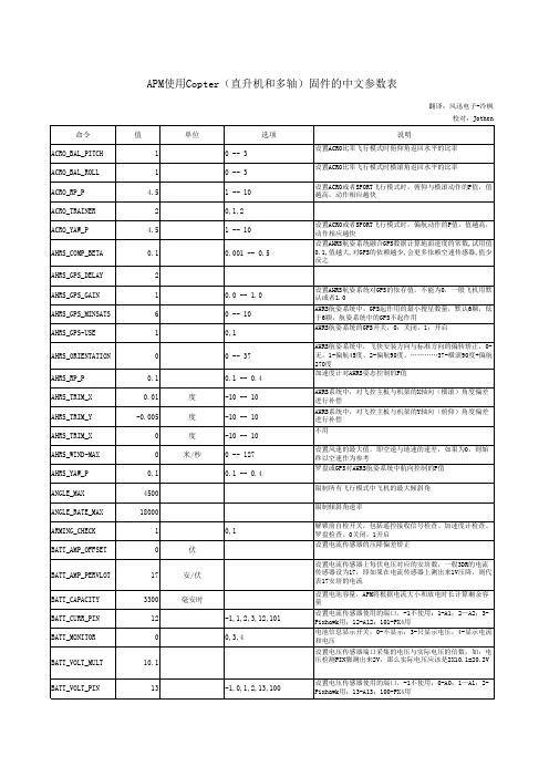
APM使用Copter(直升机和多轴)固件的中文参数表翻译:风迅电子-冷枫校对:Jothen 命令值单位选项说明ACRO_BAL_PITCH10 -- 3设置ACRO比率飞行模式时俯仰角返回水平的比率ACRO_BAL_ROLL10 -- 3设置ACRO比率飞行模式时横滚角返回水平的比率ACRO_RP_P 4.5 1 -- 10设置ACRO或者SPORT飞行模式时,俯仰与横滚动作的P值,值越高,动作相应越快ACRO_TRAINER20,1,2ACRO_YAW_P 4.5 1 -- 10设置ACRO或者SPORT飞行模式时,偏航动作的P值,值越高,动作相应越快AHRS_COMP_BETA0.10.001 -- 0.5设置AHRS航姿系统融合GPS数据计算地面速度的常数,试用值0.1,值越大,对GPS的依赖越少,会更多依赖空速传感器,值少反之AHRS_GPS_DELAY2AHRS_GPS_GAIN10.0 -- 1.0设置AHRS航姿系统对GPS的依存值,不能为0,一般飞机用默认或者1.0AHRS_GPS_MINSATS60 -- 10AHRS航姿系统中,GPS起作用的最小搜星数量,默认6颗,低于6颗,航姿系统中的GPS不起作用AHRS_GPS-USE10,1AHRS航姿系统的GPS开关,0:关闭,1;开启AHRS_ORIENTATION00 -- 37AHRS航姿系统中,飞快安装方向与标准方向的偏转矫正,0-无,1-偏航45度,2-偏航90度,…………37-横滚90度+偏航270度AHRS_RP_P0.10.1 -- 0.4加速度计对AHRS姿态控制的P值AHRS_TRIM_X0.01度-10 -- 10AHRS系统中,对飞控主板与机架的X轴向(横滚)角度偏差进行补偿AHRS_TRIM_Y-0.005度-10 -- 10AHRS系统中,对飞控主板与机架的Y轴向(俯仰)角度偏差进行补偿AHRS_TRIM_X0度-10 -- 10不用AHRS_WIND-MAX0米/秒0 -- 127设置风速的最大值,即空速与地速的速差,如果为0,则始终以空速作为参考AHRS_YAW_P0.10.1 -- 0.4罗盘或GPS对AHRS航姿系统中航向控制的P值ANGLE_MAX4500限制所有飞行模式中飞机的最大倾斜角ANGLE_RATE_MAX18000限制倾斜角速率ARMING_CHECK10,1解锁前自检开关,包括遥控接收信号检查、加速度计检查、罗盘检查。
AO4435中文资料
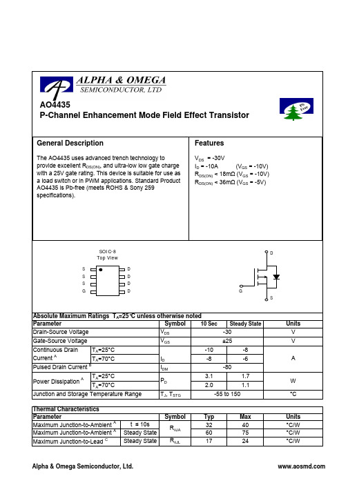
ID=-10A
1E-02
25°C 1E-03 25 THIS PRODUCT HAS BEEN DESIGNED AND QUALIFIED FOR THE CONSUMER MARKET. APPLICATIONS OR USES AS CRITICAL COMPONENTS IN LIFE SUPPORT DEVICES OR SYSTEMS ARE NOT AUTHORIZED. AOS DOES NOT ASSUME ANY LIABILITY ARISING 1E-04 20 OUT OF SUCH APPLICATIONS OR USES OF ITS PRODUCTS. AOS RESERVES THE RIGHT TO IMPROVE PRODUCT DESIGN, 1E-05 25°C 15 AND RELIABILITY WITHOUT FUNCTIONS NOTICE. 10 3 4 5 6 7 8 9 10 -VGS (Volts) Figure 5: On-Resistance vs. Gate-Source Voltage 1E-06 0.0 0.2 0.4 0.6 0.8 1.0 -VSD (Volts) Figure 6: Body-Diode Characteristics
Symbol
A A
t ≤ 10s Steady State Steady State
RθJA RθJL
Typ 32 60 17
Max 40 75 24
Units °C/W °C/W °C/W
Alpha & Omega Semiconductor, Ltd.
元器件交易网
Units V V A
W °C
Junction and Storage Temperature Range Therቤተ መጻሕፍቲ ባይዱal Characteristics Parameter Maximum Junction-to-Ambient Maximum Junction-to-Ambient Maximum Junction-to-Lead C
阿姆瑞特 QoS 用户手册说明书

阿姆瑞特流量分析整形产品用户手册北京阿姆瑞特软件有限公司2018年11月版目录第一部分:前言 (4)声明 (4)产品应用差异说明 (4)意见反馈 (4)第二部分:网络规划 (5)产品亮点与应用 (5)产品规格 (6)第三部分:网络部署 (7)网桥接入 (7)基本配置 (7)流量控制配置 (10)连接数控制配置 (16)http管控配置 (18)网关接入 (20)基本配置 (21)接口设置 (23)策略路由设置 (25)负载均衡设置 (27)端口映射设置 (29)DNS管控配置 (30)DHCP配置 (33)PPPOE认证配置 (34)Web认证配置 (45)应用分流配置 (48)PPPOE代拨网关 (51)研发背景及应用场景 (51)正确理解PPPOE代拨 (51)PPPOE代拨的基本配置: (52)代拨路由策略 (52)代拨DNS重定向策略 (53)游戏快线 (53)基本配置 (54)旁路接入 (54)基本配置 (54)第四部分:应用商店 (56)DDNS服务 (57)共享检测 (58)第五部分:设备维护 (59)维护基本原则 (59)如何获取技术支持 (60)接口维护 (61)安全维护 (63)配置备份 (65)第一部分:前言声明版权:本文的内容是阿姆瑞特流量分析整形产品用户手册。
文中的资料、说明等相关内容归北京阿姆瑞特软件有限公司所有。
本文中的任何部分未经北京阿姆瑞特软件有限公司(以下简称“阿姆瑞特”)许可,不得转印、影印或复印、发行。
修订:北京阿姆瑞特软件有限公司保留不预先通知客户而修改本文档所含内容的权利。
责任:北京阿姆瑞特软件有限公司对于您的使用或不能使用本产品而发生的任何损害不负任何赔偿责任,包括但不限于直接的、间接的、附加的个人损害或商业损失或任何其它损失。
产品应用差异说明本文挡的开发过程是基于阿姆瑞特QoS AmFlow 10.00.00。
本文档描述的部分内容可能跟您购买的设备有差异,其原因可能是您购买的设备版本低于或者高于阿姆瑞特QoS AmFlow 10.00.00。
APM4435

BVDSS
VGS = 0V, ID = -250uA
-30
V
Drain-Source On-State Resistance 漏源导通电阻 Drain-Source On-State Resistance 漏源导通电阻
RDS(on) RDS(on)
VGS = -10V, ID = -10.5A VGS = -4.5V, ID = -6.0A
Dቤተ መጻሕፍቲ ባይዱ
D
D
D
8
7
6
5
Date Code
4435G
REF. A B C D E
F
1
2
3
4
S
S
S
G
Millimeter
Min.
Max.
5.80
6.20
4.80
5.00
3.80
4.00
0°
8°
0.40
0.90
0.19
0.25
REF.
M H L J K
G
Millimeter
Min.
Max.
0.10
0.25
0.35
td(on) tr
td(off) tf
VDD = -15V, RL=15Ω ID = -1A, VGEN = -10V
RG = 6Ω
10
15
15
25
ns
110
170
70
110
Input Capacitance 输入电容 Output Capacitance 输出电容 Reverse Transfer Capacitance 反向传输电容
Features 特性 Advanced trench process technology 高级的加工技术 High Density Cell Design For Ultra Low On-Resistance
SC2443资料

Applications
u Telecommunication power supplies u DDR memory power supplies u Graphic power supplies u Servers and base stations
Typical Application Circuit
VOUT1 VP1 VIN VIN
VOUT1 VP1
VIN
VIN
VP1
24 23 22 21 20 19
VOUT1
24 23 22 21 20 19
VP1
IN1-
VOUT1 IN1-
U1 1 2 3 4 5 6
U1 1 2
CS1+
SS1/EN1
BST1
CS1-
SS1/EN1
ROSC
GDH1
ROSC
GDH1
Electrical Characteristics
Unless otherwise specified: AVCC = PVCC = 12V, VBST1 = VBST2 = 12V, SYNC = 0V, -40°C < TA = TJ < 85°C, ROSC =51.1kW.
Parameter Undervoltage Lockout AVCC Start Threshold AVCC Start Hysteresis AVCC Operating Current AVCC Quiescent Current in UVLO Channel 1 Error Amplifier Non-inverting Input Voltage Non-inverting Input Line Regulation Input Offset Voltage Inverting Input Bias Current Amplifier Transconductance Amplifier Open Loop Gain Amplifier Unity Gain Bandwidth COMP1 Switching Threshold Amplifier Output Sink Current Amplifier Output Source Current
apm8005kc电路原理

APM8005KC是一款电子元件,它的电路原理涉及多个方面。
首先,它是一个电源管理IC,负责控制和管理系统的电源供应。
具体来说,它会根据系统的需求调整电源的输出电压和电流,以确保系统正常运行。
其次,APM8005KC还具有过流保护和过热保护功能。
当电源电流过大或温度过高时,它会触发保护机制,关闭电源或降低电源的输出,以避免对系统造成损坏。
此外,APM8005KC还具有一些其他功能,例如欠压保护和自动重启动等。
这些功能可以进一步提高系统的稳定性和可靠性。
总的来说,APM8005KC的电路原理是通过各种机制和控制策略来确保系统的电源供应稳定、可靠,并在异常情况下采取相应的保护措施,以避免对系统造成损坏。
这些原理的实现需要通过电路设计和软件编程等手段来完成。
4435场效应管参数

4435场效应管参数场效应管(Field Effect Transistor,FET)是一种三端器件,由晶体管中的PN结演化而来。
它通过控制栅极与漏极之间的电场来控制电流流动,具有高输入电阻、低噪声、低功耗等优点,因此广泛应用于模拟电路和数字电路中。
以下是关于场效应管参数的详细介绍。
1.析取:场效应管由源极、漏极和栅极组成。
其中,源极是电流输入端,漏极是电流输出端,栅极用于控制电流流动。
栅极与源极之间的电场决定了漏极-源极通道的导电能力。
2.通道类型:场效应管根据通道类型可以分为N沟道(N-Channel)和P沟道(P-Channel)两种。
N沟道场效应管中,通道为N型半导体,漏极为N型,栅极为P型;P沟道场效应管中,通道为P型半导体,漏极为P型,栅极为N型。
3. 漏极-源极导通电阻(RDS(on)):RDS(on)是场效应管导通状态下的漏极-源极电阻。
它是一个关键的参数,决定了场效应管的功耗和工作温度。
RDS(on)越小,表示场效应管导通时的电阻越小,功耗也越小。
因此,低RDS(on)的场效应管适用于高功率应用,如电力电子设备。
4.最大漏极-源极电压(VDS)和最大栅极-源极电压(VGS):VDS和VGS是场效应管能够承受的最大电压。
在超过最大电压范围时,场效应管可能发生击穿或损坏。
因此,在设计电路时,应注意选择适当的场效应管,确保其能够承受设计电路中的最大电压。
5.漏极电流(ID)和栅极电流(IG):ID是从漏极流出的电流,是场效应管的输出电流。
IG是注入到栅极的电流,用于控制场效应管的导通与截止。
实际工作中,栅极电流通常很小,可以忽略。
而漏极电流与栅极电压的关系可以通过场效应管的转移特性曲线(ID-VGS曲线)来描述。
6.转移特性曲线:转移特性曲线是场效应管在不同栅极电压下的漏电流-栅极电压关系曲线。
通过转移特性曲线,可以了解场效应管的导通与截止电压范围以及漏电流与栅极电压之间的关系。
根据转移特性曲线,可以确定适合特定应用的场效应管。
4435a参数

4435a参数4435a参数是一种常用的技术术语,广泛应用于各个领域。
它是指一种特定的参数设置,用于调整和控制某个系统或设备的性能和功能。
在不同的行业和领域中,4435a参数具有不同的含义和应用。
在电子领域中,4435a参数通常用于描述电子元器件的性能和规格。
例如,对于一款电子元器件,4435a参数可以表示其电压、电流、频率等方面的特性。
这些参数对于设计和使用电子设备非常重要,可以帮助工程师们选择合适的元器件,并确保设备的正常运行。
在通信领域中,4435a参数常常用于描述无线通信系统的性能和覆盖范围。
例如,对于一款无线路由器,4435a参数可以表示其传输速率、信号强度、覆盖范围等方面的特性。
这些参数对于用户选择合适的无线设备和优化网络连接非常重要。
在工业控制领域中,4435a参数被广泛应用于调整和控制各种工业设备的性能和运行状态。
例如,对于一台机械设备,4435a参数可以表示其转速、负载、温度等方面的特性。
通过合理设置这些参数,可以提高设备的效率和稳定性,降低故障率和维修成本。
在医疗领域中,4435a参数常常用于描述医疗设备的性能和治疗效果。
例如,对于一种医疗仪器,4435a参数可以表示其功率、频率、治疗时间等方面的特性。
这些参数对于医生选择合适的治疗方案和评估治疗效果非常重要。
总之,4435a参数是一种重要的技术术语,广泛应用于各个领域。
它可以帮助人们了解和控制系统或设备的性能和功能,从而提高工作效率和产品质量。
在不同的行业和领域中,人们需要根据具体的需求和应用场景,合理设置和调整4435a参数,以达到最佳的效果和效益。
卡特品牌的模型44315旋转快速连接器维护和过程手册说明书
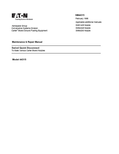
SM64200 N ozzleT o M ate V arious Carter B rand N ozzlesSM 61428 N ozzle SM 64348 N ozzleModel 44315Swivel Quick DisconnectA pplicable additional manuals :SM 44315February 1998Maintenance & Repair ManualAerospace GroupConveyance Systems DivisionCarter ® Brand Ground Fueling EquipmentSM44315 February 1, 1998TABLE OF CONTENTSPAGE1.0INTRODUCTION (3)2.0EQUIPMENT DESCRIPTION (3)3.0TABLE OF OPTIONS (3)4.0SAFETY INSTRUCTIONS (3)5.0 DISASSEMBLY (4)6.0 INSPECTION (5)7.0 REASSEMBLY (5)8.0 TEST (5)9.0 ILLUSTRATED PARTS CATALOG (6)FIGURE 1 (7)- 2 -SM44315February 1, 1998- 3 -MAINTENANCE, OVERHAUL & TEST INSTRUCTIONS CARTER MODEL 44315 SWIVEL QUICK DISCONNECT1.0INTRODUCTIONThis manual furnishes detailed instructions covering th e maintenance and overhaul of Eaton's Carter brand Model 44315, Swivel Quic k Disconnect Assembly.The 44315 Swivel Disconnect is available in many variations of inlet configurations. These are obtained byprocuring different "dash" numbers of the basic Model number 44315. Each of t hese variations corresponds to a different "option" letter on Model 61428,64348, or 64200 Nozzles when procured as a part of the nozzle. Refer t o paragraph 3.0 for a detailed explanatio n of the various options.2.0EQUIPMENT DESCRIPTION Model 44315 Swivel Quick Disconnect is designed to be used as a part of Model 61428, 64200 or 64348 Nozzles to provide connection to various sizes and types of hose fittings and to providea quick means of disconnecting the nozzle from the hose for inspection of the strainer utilized therein. The outlet adapter that mates the nozzle is also the male half of the swivel.3.0TABLE OF OPTIONSThe Unit is available with various inlet thread sizes and types as shown below. The corresponding options to the 61428, 64200 or 64348 Nozzles are also shown.Model Number DescriptionNozzle Option44315-1 2 1/2" NPT Inlet Thd 6H 44315-2 2 1/2" BSPP Inlet Thd 6K 44315-33" NPT Inlet Thd 6L 44315-43" BSPP Inlet Thd 6M 44315-52" BSPP Inlet Thd 6N 44315-62" NPT Inlet Thd 6P 44373-6060-mesh Screen B 44373-100100-mesh ScreenC4.0SAFETY INSTRUCTIONSThe Swivel Disconnect described herein has two separate safety systems built into it to assure that the unit can not be inadvertently disassembled from the hose. The unit is held together with a bayonet type joint requiring a rotation motion to disconnect one part from the other. This joint is locked by a spring loaded ring that prevents the rotation unless the ring is pulled away from the joint. In addition to the locking ring, there are two screws that are also designed to prevent rotation of the bayonet feature unless loosened. These screws are normally wire locked.SM44315February 1, 1998- 4 -NOTE:Do not operate the nozzle with this Swivel Disconnect connected unless theRetainer(10) is in place and the Screws (4) are fully installed and wire locked.5.0DISASSEMBLY5.1Remove the n ozzle/s wivel q uickd isconnect from the end of the hose.S e p a r a t e t h e s w i v e l q u i c kd isconnect from the nozzle. Refer toSM61428 service manual, paragraph6.2 for instructions on this operation.5.2Remove Lockwire (3) from Screws(4). Take note of the method oflockwiring for duplication uponreassembly.5.3Remove Screws (4) and set aside.Note: Older units will have a Washer(5A) under the head of each Screw(4). Newer units will have a bump onthe outer rim of the Housing (6), nothave the Washer (5A) and will havean anti-rotation Pin (5) to facilitateinstallation of the unit. Do notremove the Pin (5) unless it isdamaged and replacement is needed.5.4Holding the Unit with the threadedend in the right hand and the adapterend in the left, pull the black plasticRetainer (10) away from the Housing(6). Rotate the Housing in eitherdirection and pull it away from theAdapter (9) to disassemble.5.5Remove the Quad Ring (7) from theHousing (6). (Older units may have atwo piece seal consisting of a plasticSeal and a Spring that is mountedinside the Seal cavity. These twoparts may be replaced with the QuadRing (7).) Do not remove the WaveWasher (8) unless it is to be replaced.This washer is used to assure electricalcontinuity between the Housing (6) andAdapter (9). If it is necessary to removethe Washer (8) it can only beaccomplished by bending it out of shape.The Washer (8) is intended to be"wavey" and the precision of the wavesare of no consequence as long as thewaves are sufficient to make contactbetween the male and female halves ofthe Swivel.5.6If a Screen (1) is present it may beremoved for replacement or cleaning byremoving its Retainer (2) first.5.7The removal of the Curved Washer (11),Shroud (12), noting the direction inwhich it is installed for use inreassembly, Ring (13), and Retainer (10)should only be done if any of them areto be replaced. The Shroud (12) iscompressed against the Curved Washer(11) to allow removal of the Ring (13).Once the Ring is removed the other partsmay be removed.5.8The Teflon Seal (15) and O-ring (14)should only be removed if the Seal (15)is damaged. The O-ring is a flurosiliconecompound and is not affected by age. Toremove it use an "o-ring pick" beingcareful not to damage the Adapter (9).Once removed, the Seal (15) must bereplaced as well as the O-ring (14).SM44315February 1, 1998- 5 -6.0INSPECTIONIt is recommended that the Quad Ring (7)(or the older Seal and Spring) be replaced upon each overhaul of the Unit. O-ring (14) should be replaced only if damaged or the Seal (15) is to be replaced.Inspect all metal parts for dings, gouges,abrasions, etc. Use 320 grit paper to smooth and remove sharp edges. Replace any part with damage exceeding 15% of local wall thickness. Use alodine 1200 to touch up bared aluminum. Carefully check the edges of the ball race in the Adapter (9) for excessive wear or burrs.This part is dry film lubricated. If the ball groove is shiny the part should be replaced or the dry film lubricant be reapplied. An easily used aerosol can of Perma-S ilk G dry film lubricant can be obtained from 3M Corporation, 6940 Farmdale Ave., North Hollywood, CA 91605. Any burrs should be removed with abrasive. Excessive burring may result in hanging up of the part within the Nozzle Body making it impossible to disassemble in the future. Check the Retainer (10) for cracks. Replace if necessary.7.0REASSEMBLY7.1Reassemble in reverse order of disassembly (Refer to Figure 1),observing the following:7.1.1Make certain all components are clean and free from oil, grease, or any other corrosion resistant compound on all interior or exterior surfaces. Wash all parts with cleaning solvent, Federal Specification P-D-680, and dry thoroughly with a clean, lint-free cloth or compressed air.WARNING:Use cleaning solvent in a well-ventilated area. Avoid breathing of fumes and excessive solvent contact with skin. Keep away from openflame NOTE: A light coat of petrolatum,Federal Specification VV-P-236 or equivalent commercial quality, can beapplied to all o-rings and screws for ease of installation.7.1.2Install Quad Ring (7) into Housing (6).7.1.3If Wave Washer (8) is being installed it will be necessary to bend it somewhat to properly install it. The shape of the "waves" are not critical and the part will be flattened out somewhat upon reassembly to the Adapter (9).7.1.4When installing Shroud (12) be sure that it is oriented such that it will cover up and retain the Ring (13) upon final assembly.7.1.5Upon reassembly of the Screws (4),Lockwire (3) should be installed to prevent loosening of the Screws (4). On newer units the rotation of the Housing (6) will be stopped at the correct location by the Pin (5).8.0TEST8.1The Unit shall be tested as a part of a completed nozzle as instructed in SM61428 or SM54348.8.2Test conditions8.2.1Test media shall be Calibration Test Fluid per MIL-C-7024, Stoddard Solvent (Federal Specification P-D-680), JP-4 per MIL-J-5624D at 75o + 15o F, Jet A or equivalent.SM44315February 1, 1998 8.3Functional TestAs mentioned above the Unitshould be tested in accordancewith the appropriate paragraphsof SM61428 or SM64348.9.0ILLUSTRATED PARTS CATALOGTable 1.0 tabulates the parts and sub-assemblies comprising the 44315-* Swivel QuickDisconnect Assembly and 44373-60 or -100 Screen Assemblies. The item numbers of thetable are keyed to the exploded view of the Swivel Assembly diagramed in Figure 1.TABLE 1.0Units Per Nozzle Spares/ Item Part Number Description Assembly Option10 Units/Yr.144373-60Screen Assy, 60-mesh..............1B144373-100Screen Assy, 100-mesh............1C11A208092-60Screen, 60-mesh.................1B-1B208092-100Screen, 100-mesh...............1C-1C208091Ring, Retainer....................1B,C-244317-*QD Female Half Assy..............1**-3GF20995C32Lockwire............................A/R**104GF24673-9Screw.................................2**-5 92373A126 Pin......................................1 ** -5A GF960C416Washer...............................2**-6207813-1Housing, 2 1/2 NPT...........1H-6A207813-2Housing, 2 1/2 BSPP.........1K-6B207813-3Housing, 3 NPT.................1L-6C207813-4Housing, 3 BSPP................1M-6D207813-5Housing, 2 BSPP................1N-6E207813-6Housing, 2 NPT.................1P-7210174-337Quad Ring..........................1**108207995Washer, Wave....................1**2 9-1544316QD Male Half Assy...........1**-9207809Adapter..............................1**-10207810Retainer..............................1**-11207811Washer, Curved.................1**-12208001Shroud................................1**-13RS-318-S Ring, Retainer....................1**-14M25988/1-040O-Ring...............................1**515207807Seal, Swivel.......................1**5For various seal kits to overhaul or repair this item as a part of a nozzle please refer to the service manual for the appropriate nozzle, SM61429, SM64200 or SM64348.*Use the same dash number as that used on the Housing (6).**Used on Nozzle Options H, K, L, M, N & P.- 6 -SM44315February 1, 1998FIGURE 1Aerospace GroupConveyance Systems Division 9650 Jeronimo Rd Irvine, CA 92618 Ph (949) 452-9500 Fax (949) 452-9992。
AP4435GM中文资料

P-CHANNEL ENHANCEMENT MODE POWER MOSFET▼ Simple Drive Requirement BV DSS -30V ▼ Low On-resistanceR DS(ON)20m Ω▼ Fast Switching CharacteristicI D-9ADescriptionAbsolute Maximum RatingsSymbol Units VDS V V GSV I D @T A =25℃A I D @T A =70℃A I DMA P D @T A =25℃W W/℃T STG ℃T J℃Symbol Value Unit Rthj-aMaximum Thermal Resistance, Junction-ambient350℃/WData and specifications subject to change without notice 1200811216AP4435GMRating - 30+ 20-90.02ParameterDrain-Source Voltage Gate-Source Voltage Continuous Drain Current 3Linear Derating Factor Storage Temperature RangeContinuous Drain Current 3-7.3Pulsed Drain Current 1-50RoHS-compliant ProductThermal DataParameterTotal Power Dissipation 2.5-55 to 150Operating Junction Temperature Range-55 to 150Advanced Power MOSFETs from APEC provide the designer with the best combination of fast switching,ruggedized device design, low on-resistance and cost-effectiveness.The SO-8 package is widely preferred for all commercial-industrial surface mount applications and suited for low voltage applications such as DC/DC converters.S SS GDD DDSO-8Electrical Characteristics@T j =25oC(unless otherwise specified)Symbol ParameterTest ConditionsMin.Typ.Max.Units BV DSS Drain-Source Breakdown Voltage V GS =0V, I D =-250uA -30--V R DS(ON)Static Drain-Source On-Resistance 2V GS =-10V, I D =-7A --20m ΩV GS =-4.5V, I D =-5A--32m ΩV GS(th)Gate Threshold Voltage V DS =V GS , I D =-250uA -1--3V g fs Forward Transconductance V DS =-10V, I D =-7A -16-S I DSS Drain-Source Leakage Current V DS =-30V, V GS =0V ---1uA Drain-Source Leakage Current (T j =70o C)V DS =-24V, V GS =0V---25uA I GSS Gate-Source Leakage V GS =+20V --+100nA Q g Total Gate Charge 2I D =-7A -1829nC Q gs Gate-Source Charge V DS =-24V -3-nC Q gd Gate-Drain ("Miller") Charge V GS =-4.5V -10-nC t d(on)Turn-on Delay Time 2V DS =-15V -8-ns t r Rise TimeI D =-1A- 6.6-ns t d(off)Turn-off Delay Time R G =3.3Ω,V GS =-10V -44-ns t f Fall Time R D =15Ω-34-ns C iss Input Capacitance V GS =0V -11751690pF C oss Output CapacitanceV DS =-25V -195-pF C rssReverse Transfer Capacitancef=1.0MHz-190-pFSource-Drain DiodeSymbol ParameterTest ConditionsMin.Typ.Max.Units V SD Forward On Voltage 2I S =-2.1A, V GS =0V ---1.2V t rr Reverse Recovery Time2I S =-7A, V GS =0V,-28-ns Q rrReverse Recovery ChargedI/dt=100A/µs-18-nCNotes:1.Pulse width limited by Max. junction temperature.2.Pulse testTHIS PRODUCT IS SENSITIVE TO ELECTROSTATIC DISCHARGE, PLEASE HANDLE WITH CAUTION.USE OF THIS PRODUCT AS A CRITICAL COMPONENT IN LIFE SUPPORT OR OTHER SIMILAR SYSTEMS IS NOT AUTHORIZED.APEC DOES NOT ASSUME ANY LIABILITY ARISING OUT OF THE APPLICATION OR USE OF ANY PRODUCT OR CIRCUIT DESCRIBED HEREIN; NEITHER DOES IT CONVEY ANY LICENSE UNDER ITS PATENT RIGHTS, NOR THE RIGHTS OF OTHERS.APEC RESERVES THE RIGHT TO MAKE CHANGES WITHOUT FURTHER NOTICE TO ANY PRODUCTS HEREIN TO IMPROVE RELIABILITY, FUNCTION OR DESIGN.2AP4435GM3.Surface mounted on 1 in 2 copper pad of FR4 board, t <10sec ; 125 ℃/W when mounted on Min. copper pad.AP4435GMFig 1. Typical Output Characteristics Fig 2. Typical Output CharacteristicsFig 3. On-Resistance v.s. Gate VoltageFig 4. Normalized On-Resistancev.s. Junction TemperatureFig 5. Forward Characteristic ofFig 6. Gate Threshold Voltage v.s. Reverse DiodeJunction TemperatureFig 7. Gate Charge CharacteristicsFig 9. Maximum Safe Operating Area Fig 10. Effective Transient Thermal ImpedanceFig 11. Transfer Characteristics Fig 12. Gate Charge CircuitAP4435GMG。
4435芯片

4435芯片4435芯片是一种集成电路产品,是一种嵌入式微控制器。
下面是关于4435芯片的1000字详细介绍:4435芯片是由某公司研发的一款高性能嵌入式微控制器。
该芯片采用了先进的40纳米工艺制造,在同类产品中具有很高的性能和能效优势。
4435芯片主要用于各种嵌入式系统中,如智能家居、智能终端设备、工业自动化等领域。
首先,4435芯片具有非常强大的计算和处理能力。
它采用了ARM Cortex-M4内核,主频高达100MHz,配备了128KB的片内闪存和32KB的RAM。
这使得芯片可以实现复杂的算法和多任务处理,为各种应用提供强大的计算支持。
其次,4435芯片还具备丰富的外设功能。
它集成了多个模拟和数字外设,如多种通信接口(UART、SPI、I2C等)、多个定时器和PWM输出、多个模拟输入和输出通道等。
这些外设可以满足不同应用对于各种输入输出的需求,提供了灵活性和扩展性。
此外,4435芯片还具备低功耗特性。
通过在设计过程中采用了多种低功耗技术,4435芯片在工作时能够有效降低功耗,延长设备的续航时间。
尤其对于那些需要长时间待机或运行的应用来说,低功耗特性是非常重要的。
4435芯片还具备良好的可靠性和稳定性。
在设计和生产过程中,采用了严格的质量控制体系和可靠性验证方法,保证了产品的品质和性能稳定性。
芯片内部还具备多种自我保护和错误处理机制,可以提供良好的故障检测和容错能力。
除此之外,4435芯片还具备丰富的软件支持。
厂家提供了完善的软件开发工具和开发环境,并提供了丰富的驱动库和示例代码,帮助开发者快速上手和进行项目开发。
同时,4435芯片还支持多种常用的实时操作系统(RTOS),为开发者提供更加灵活和高效的软件开发平台。
综上所述,4435芯片是一款功能强大、稳定可靠的嵌入式微控制器。
它具备高性能的计算能力、丰富的外设功能、低功耗特性和良好的软件支持,适用于各种嵌入式应用。
未来随着物联网和智能化的发展,4435芯片将扮演越来越重要的角色,带给人们更多智能、便捷、高效的生活体验。
4435场效应管参数
4435场效应管参数场效应管是一种三端器件,由源极、漏极和栅极组成。
在场效应管中,电流主要由栅极控制,因此栅极电压和栅极电流是场效应管重要的参数。
场效应管有很多参数,其中一些主要的参数包括:1. 阈值电压(Vth):阈值电压是指当栅极电压超过一定值时,场效应管开始导通的电压。
阈值电压决定了场效应管的开启和关闭状态。
2. 饱和电流(Idsat):饱和电流是指当场效应管工作在饱和区时,从漏极到源极的电流。
饱和电流的大小取决于栅极电压和源漏电压。
3. 前向跨导(gm):前向跨导是指场效应管的输出电流与输入电压之间的关系,也可以理解为栅极电流对栅极电压的敏感度。
前向跨导越大,表示场效应管的增益越高。
4.漏极电流(Id):漏极电流是指场效应管从源极到漏极的电流,大小一般受到栅极电压和源漏电压的影响。
5. 转导电导(gds):转导电导是指漏极电流对源漏电压的敏感度。
转导电导越小,表示场效应管的漏极电流对源漏电压更不敏感,是理想的开关特性。
6. 耗散功率(Pdiss):耗散功率是指场效应管在工作时产生的热量,其大小取决于场效应管的漏极电流和漏极电压。
若耗散功率过大,可能会导致场效应管过热而损坏。
7. 负载线性区电流(ID-linear):负载线性区电流是指场效应管工作在线性区时,从漏极到源极的电流。
负载线性区电流的大小与场效应管的线性度和放大能力有关。
8. 最大漏源电压(VDS-max):最大漏源电压是指场效应管所能耐受的最大漏源电压。
若电压超过该值,可能会导致场效应管损坏。
9. 最大栅极源极电压(VGS-max):最大栅极源极电压是指场效应管所能耐受的最大栅极源极电压。
若电压超过该值,可能会导致场效应管损坏。
10. 最大栅源电压(VGS-th-max):最大栅源电压是指场效应管所能耐受的最大栅源电压。
若电压超过该值,可能会导致场效应管损坏。
除了以上提到的参数,还有许多其他参数可以衡量场效应管的性能和特性。
场效应管的参数选择取决于具体的应用场景和要求。
APM4410KC-TR中文资料
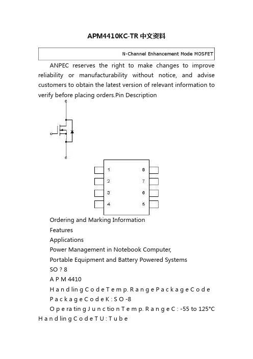
APM4410KC-TR中文资料ANPEC reserves the right to make changes to improve reliability or manufacturability without notice, and advise customers to obtain the latest version of relevant information to verify before placing orders.Pin DescriptionOrdering and Marking InformationFeaturesApplicationsPower Management in Notebook Computer,Portable Equipment and Battery Powered SystemsSO ? 8A P M 4410H a n d lin g C o d e T e m p. R a n g e P a c k a g e C o d eP a c k a g e C o d e K : S O -8O p e ra tin g J u n c tio n T e m p. R a n g e C : -55 to 125°C H a n d lin g C o d e T U : T u b eT R : T a p e & R e e lA P M 4410 K :A P M 4410X X X X XX X X X X - D a te C o d eAbsolute Maximum Ratings (T A = 25°C unless otherwise noted)N-Channel MOSFETSS S S GDD D D ? 30V/11.5A, R DS(ON) = 9m ?(typ.) @ V GS = 10VR DS(ON) =14.5m ?(typ.) @ V GS = 4.5VHigh Density Cell Design ? Reliable and Rugged ? SO-8 PackageThermal CharacteristicsElectrical Characteristics (T A=25°C unless otherwise noted)Notesa : Guaranteed by design, not subject to production testingb : Pulse test ; pulse width ≤300μs, duty cycle ≤ 2% Typical Characteristics02468101020304050Output CharacteristicsV DS -Drain-to-Source Voltage (V)I D S -D r a i n C u r r e n t (A )0123451020304050Transfer CharacteristicsV GS -Gate-to-Source Voltage (V)I D S -D r a i n C u r r e n t (A )-50-2502550751001251500.20.40.60.81.01.21.4Threshold Voltage vs. Junction T emperature T j -Junction T emperature (°C)05101520253035 0.0000.0040.0080.0120.0160.020On-Resistance vs. Drain CurrentI DS -Drain Current (A)R D S (O N )-O n -R e s i s ta n c e (?)V G S (t h )-T h r e s h o l d V o l t a g e (V )(N o r m a l i z e d )918273645246810Typical Characteristics Cont.0246810On-Resistance vs. Gate-to-Source Voltage R D S (O N )-O n -R e s i s t a n c e (?) Gate Voltage (V)-50-2502550751001251500.000.250.500.751.001.251.501.752.00On-Resistaence vs. Junction T emperatureR D S (O N )-O n -R e s i s t a n c e (?)(N o r m a l i z e d ) T j -Junction Temperature (°C)Gate ChargeQ G -T otal Gate Charge (nC)V G S -G a t e -t o -S o u r c e V o l t a g e (V )0510********10001500200025003000Capacitance CharacteristicsV DS -Drain-to-Source Voltage (V)C -C a p a c i t a n c e (p F )Typical Characteristics Cont.0.00.20.40.60.8 1.0 1.2 1.411050Source-Drain Diode Forward Voltage I S D -S o u r c e C u r r e n t (A )V SD -Source to Drain Voltage0.010.1110020406080Time (sec)Single Pulse PowerP o w e r (W )1E -41E -30.010.11100.0Square Wave Pulse Duration (sec)N o r m a l i z e d E f f e c t i v e T r a n s i e n t T h e r m a l I m p e d a n c eNormalized Transient Thermal Transient Impedence, Junction to AmbientPackaging InformationSOP-8 pin ( Reference JEDEC Registration MS-012)Reflow Condition (IR/Convection or VPR Reflow) Physical SpecificationsPre-heat temperature183 CPeak temperatureTime°t e m p e r a t u r eClassification Reflow ProfilesPackage Reflow ConditionsReliability test programCarrier Tape & Reel Dimensions(mm)Cover Tape DimensionsCustomer ServiceAnpec Electronics Corp. Head Office :5F, No. 2 Li-Hsin Road, SBIP, Hsin-Chu, T aiwan, R.O.C. T el : 886-3-5642000Fax : 886-3-5642050Taipei Branch :7F, No. 137, Lane 235, Pac Chiao Rd.,Hsin Tien City, Taipei Hsien, T aiwan, R. O. C. T el : 886-2-89191368Fax : 886-2-89191369。
八脚芯片4435工作原理
八脚芯片4435工作原理
八脚芯片4435是一种用于电源管理的集成电路。
它的工作原理可以分为以下几个方面:
1. 电源输入:八脚芯片4435通常通过一对输入脚获得电源输入,其标称工作电压范围一般为
2.5V至5.5V。
这些输入脚通常与外部电源连接,供电给芯片内部的各个模块。
2. 电源管理:芯片的主要工作是对电源进行管理。
它内部包含多个模块来完成各种功能,如电压调节器、电压监测器、过压保护、短路保护等。
这些模块相互协作,确保芯片输出的电源稳定可靠。
3. 电源输出:八脚芯片4435通常具有多个输出脚,用于提供不同电源信号给外部电路。
这些输出脚可能包括正负电压输出线路、开关控制输出以及其他电源输出。
4. 外部元件:芯片通常需要外部元件的辅助来实现更为灵活的功能。
这些外部元件可以是电阻、电容、二极管等。
根据具体的设计需求,这些元件需要正确选配和布局,以确保芯片的正常工作。
总之,八脚芯片4435通过对电源进行管理,实现了对电源的稳定输出以及多种保护功能。
通过与外部元件的配合,可以满足不同应用场景对电源的要求。
TSM4435中文资料
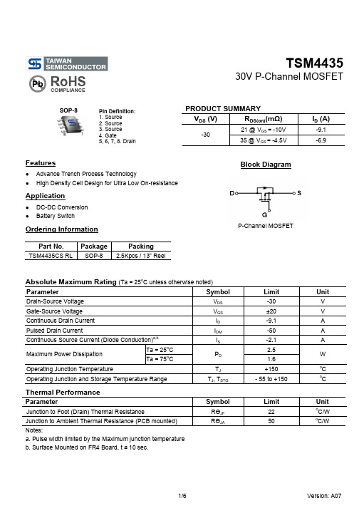
TSM443530V P-Channel MOSFETSOP-8Features● Advance Trench Process Technology● High Density Cell Design for Ultra Low On-resistanceApplication● DC-DC Conversion ● Battery SwitchOrdering InformationPart No.PackagePackingTSM4435CS RLSOP-82.5Kpcs / 13” ReelAbsolute Maximum Rating (Ta = 25o C unless otherwise noted)ParameterSymbolLimitUnitDrain-Source Voltage V DS -30 V Gate-Source Voltage V GS ±20 V Continuous Drain Current I D -9.1 A Pulsed Drain CurrentI DM -50 A Continuous Source Current (Diode Conduction)a,bI S -2.1 A Ta = 25oC 2.5 Maximum Power Dissipation Ta = 75o CP D 1.6 WOperating Junction TemperatureT J +150 o C Operating Junction and Storage Temperature RangeT J , T STG- 55 to +150oCThermal PerformanceParameterSymbolLimitUnitJunction to Foot (Drain) Thermal ResistanceR ӨJF 22 o C/WJunction to Ambient Thermal Resistance (PCB mounted) R ӨJA50oC/WNotes:a. Pulse width limited by the Maximum junction temperatureb. Surface Mounted on FR4 Board, t ≤ 10 sec.PRODUCT SUMMARY V DS (V) R DS(on)(m Ω)I D (A)21 @ V GS = -10V -9.1 -3035 @ V GS = -4.5V-6.9Block DiagramP-Channel MOSFETPin Definition: 1. Source 2. Source 3. Source 4. Gate5, 6, 7, 8. DrainTSM443530V P-Channel MOSFETElectrical SpecificationsParameterConditionsSymbolMinTypMaxUnitStaticDrain-Source Breakdown Voltage V GS = 0V, I D = -250uA BV DSS -30 -- -- V Gate Threshold Voltage V DS = V GS , I D = -250µA V GS(TH) -1 -- -3 V Gate Body LeakageV GS = ±20V, V DS = 0V I GSS -- -- ±100 nA Zero Gate Voltage Drain Current V DS = -30V, V GS = 0V I DSS -- -- -1.0 µA On-State Drain Current aV DS = -5V, V GS = -10V I D(ON) -40 -- -- A V GS = -10V, I D = -9.1A -- 17 21 Drain-Source On-State Resistance aV GS = -4.5V, I D = -6.9A R DS(ON) -- 25 35 m Ω Forward Transconductance aV DS = -10V, I D = -9.1A g fs -- 24 -- S Diode Forward Voltage I S = -2.1A, V GS = 0VV SD -- -0.8 -1.2 V Dynamic bTotal Gate Charge Q g -- 3370 Gate-Source Charge Q gs -- 5.8 -- Gate-Drain Charge V DS = -15V, I D = -9.1A, V GS = -10VQ gd -- 8.6 -- nC Input Capacitance C iss -- 1573 1900 Output CapacitanceC oss -- 319 -- Reverse Transfer Capacitance V DS = -15V, V GS = 0V, f = 1.0MHzC rss--211295 pFSwitching cTurn-On Delay Time t d(on) -- 10 15 Turn-On Rise Time t r -- 15 25 Turn-Off Delay Timet d(off)-- 110 170 Turn-Off Fall Time V DD = -15V, R L = 15Ω, I D = -1A, V GEN = -10V, R G = 6Ωt f --70110nSa. pulse test: PW ≤300µS, duty cycle ≤2%b. For DESIGN AID ONLY, not subject to production testing.b. Switching time is essentially independent of operating temperature.TSM443530V P-Channel MOSFETElectrical Characteristics Curve (Ta = 25o C, unless otherwise noted)Output CharacteristicsTransfer CharacteristicsOn-Resistance vs. Drain CurrentGate ChargeOn-Resistance vs. Junction TemperatureSource-Drain Diode Forward VoltageTSM443530V P-Channel MOSFETElectrical Characteristics Curve (Ta = 25o C, unless otherwise noted)On-Resistance vs. Gate-Source VoltageThreshold VoltageSingle Pulse PowerNormalized Thermal Transient Impedance, Junction-to-AmbientTSM443530V P-Channel MOSFETSOP-8 Mechanical DrawingMarking DiagramY = Year Code M = Month Code(A =Jan, B =Feb, C =Mar, D =Apl, E =May, F =Jun, G =Jul, H =Aug, I =Sep, J =Oct, K =Nov, L =Dec) L = Lot CodeSOP-8 DIMENSION MILLIMETERS INCHES DIM MIN MAX MIN MAX. A 4.80 5.00 0.189 0.196 B 3.80 4.00 0.150 0.157 C 1.35 1.75 0.054 0.068 D 0.35 0.49 0.014 0.019 F 0.40 1.25 0.016 0.049G 1.27BSC 0.05BSC K 0.10 0.25 0.004 0.009 M 0º 7º 0º 7º P 5.80 6.20 0.229 0.244 R0.25 0.50 0.010 0.019TSM443530V P-Channel MOSFETNoticeSpecifications of the products displayed herein are subject to change without notice. TSC or anyone on its behalf, assumes no responsibility or liability for any errors or inaccuracies.Information contained herein is intended to provide a product description only. No license, express or implied, to any intellectual property rights is granted by this document. Except as provided in TSC’s terms and conditions of sale for such products, TSC assumes no liability whatsoever, and disclaims any express or implied warranty, relating to sale and/or use of TSC products including liability or warranties relating to fitness for a particular purpose, merchantability, or infringement of any patent, copyright, or other intellectual property right.The products shown herein are not designed for use in medical, life-saving, or life-sustaining applications. Customers using or selling these products for use in such applications do so at their own risk and agree to fully indemnify TSC for any damages resulting from such improper use or sale.。
ao4435典型应用电路
ao4435典型应用电路
PAL/GAL的4435典型应用
PAL(程序化可编程逻辑器件)和GAL(组合可编程逻辑器件)对于电路来说是非常重要的一部分,4435具有异步和同步功能的特点。
PAL/GAL的4435它可以用来替代微机控制的大型输出。
它提供了一个神奇的,可重配置并具有完成度高的模块。
1,PAL/GAL 4435实现多频分频器:
主要用于存储和控制其他逻辑从而实现多频分频,如实现蜂鸣器的频率控制。
在这个例子中,用PAL/GAL 4435来实现三频分频:
用PAL/GAL 4435来实现单系统或多系统容灾,例如两个系统之间重发信号,一个程序化可编程逻辑4435做为容灾装置,提供一种重发信号以实现系统之间的同步,以确保系统可靠性,容灾原理和应用可以参考TTL&TM 容灾系统结构。
PAL/GAL 4435可以作为时钟分频器,用于实现一些芯片的低频时钟的控制,与定时器结合形成较大的延时。
例如:当某个节点的时钟源频率比周期定时器要低,PAL/GAL 4435可以实现时钟频率的降低和滤波,实现时钟的长期稳定性,也可以实现指定时间的控制,有助于提高系统的可用性。
PAL/GAL 4435可以用作接口模块,当需要连接电脑、网络和移动端设备时,可以将PAL/GAL 4435电路用于接口模块。
例如:用PAL/GAL 4435模块来连接常见的接口,例如RS-232、RS-485、Ethernet和USB等,以及一些无线传输介质,例如WiFi、蓝牙和其他低功率无线介质。
同时,它还可以用于键盘输入等高级设备。
总而言之,PAL/GAL 4435在其多种典型使用电路中能发挥出各自的作用,可以说是电路设计人员不可或缺的了解元件。
4435a参数
4435a参数
【最新版】
目录
1.4435a 参数简介
2.4435a 参数的具体内容
3.4435a 参数的应用领域
4.4435a 参数的重要性
正文
一、4435a 参数简介
4435a 参数是一种常用于电子设备中的参数,主要用来描述电子设备的性能和特性。
在众多的电子设备参数中,4435a 参数具有较高的实用价值和广泛的应用领域。
二、4435a 参数的具体内容
1.电流:4435a 参数中的电流是指电子设备在工作过程中所能承受的最大电流值。
电流过大可能会导致设备过热,从而影响设备的性能和寿命。
2.电压:4435a 参数中的电压是指电子设备正常工作所需的电压值。
电压过高或过低都可能导致设备性能下降,甚至损坏设备。
3.功率:4435a 参数中的功率是指电子设备在单位时间内所消耗的能量。
功率过大可能导致设备过热,影响设备寿命。
4.频率:4435a 参数中的频率是指电子设备在单位时间内所完成的工作循环次数。
频率过高可能导致设备过热,影响设备寿命。
三、4435a 参数的应用领域
4435a 参数广泛应用于各种电子设备中,如电源、信号处理器、放大器等。
这些设备在设计、生产和使用过程中,都需要严格遵循 4435a 参
数的要求,以确保设备的性能和寿命。
四、4435a 参数的重要性
4435a 参数对于电子设备的性能和寿命具有重要意义。
遵循 4435a 参数的要求,可以保证电子设备在工作过程中的稳定性和可靠性。
同时,4435a 参数还可以为电子设备的设计、生产和使用提供重要的参考依据。
4435a参数

4435a参数摘要:一、4435a 参数的背景和意义1.4435a 参数的定义和作用2.在我国相关领域的应用二、4435a 参数的计算方法1.一般计算方法2.针对特定情况的特殊计算方法三、4435a 参数的优化与调整1.影响4435a 参数优化的因素2.优化方法及实践案例四、4435a 参数在实际应用中的挑战与解决策略1.面临的问题和挑战2.解决方案及未来发展方向正文:4435a 参数,作为一个关键参数,在我国的许多领域都有着广泛的应用。
本文首先介绍了4435a 参数的背景和意义,然后详细阐述了其计算方法,接着讨论了4435a 参数的优化与调整,最后分析了在实际应用中可能面临的挑战及解决策略。
一、4435a 参数的背景和意义4435a 参数是描述某一特定现象或过程的重要指标。
在我国,4435a 参数的研究和应用已经取得了显著的成果,为各类工程项目提供了有力的支持。
二、4435a 参数的计算方法计算4435a 参数的方法有很多,但一般都可以归结为以下几个步骤:首先,收集相关数据和信息;然后,通过特定的计算公式进行计算;最后,根据实际需求对结果进行修正和调整。
对于某些特殊情况,还需要采用特殊的计算方法。
三、4435a 参数的优化与调整为了使4435a 参数更好地满足实际需求,需要对其进行优化与调整。
影响4435a 参数优化的因素有很多,包括工程项目的具体要求、计算方法的选择等。
针对这些因素,可以通过改进计算方法、引入新的计算工具等手段进行优化。
四、4435a 参数在实际应用中的挑战与解决策略在实际应用过程中,4435a 参数面临诸多挑战,如数据采集困难、计算过程复杂等。
为应对这些挑战,可以通过提高数据采集技术、研发新的计算方法等途径来解决问题。
- 1、下载文档前请自行甄别文档内容的完整性,平台不提供额外的编辑、内容补充、找答案等附加服务。
- 2、"仅部分预览"的文档,不可在线预览部分如存在完整性等问题,可反馈申请退款(可完整预览的文档不适用该条件!)。
- 3、如文档侵犯您的权益,请联系客服反馈,我们会尽快为您处理(人工客服工作时间:9:00-18:30)。
ANPEC reserves the right to make changes to improve reliability or manufacturability without notice, and advise customers to obtain the latest version of relevant information to verify before placing orders.
APM4435K
Features
Applications
• Power Management in Notebook Computer,
Portable Equipment and Battery Powered Systems
Pin Description
Ordering and Marking Information
P-Channel MOSFET
APM4435
Handling Code Temp. Range Package Code
Package Code K : SOP-8
Operating Junction Temp. Range C : -55 to 150C Handling Code
TR : Tape & Reel Lead Free Code
L : Lead Free Device Blank : Original Device APM4435 K :
XXXXX - Date Code
Lead Free Code APM4435XXXXX
• -30V/-8A ,
R
DS(ON)
=16m Ω
(typ.) @ V
GS =-10V
R
DS(ON)=24m Ω(typ.) @ V GS =-4.5V
• Super High Dense Cell Design • Reliable and Rugged • SOP-8 Package
•
Lead Free Available (RoHS Compliant)
Top View of SOP − 8
G
(4)(1, 2, 3)(5, 6, 7, 8)
Note: ANPEC lead-free products contain molding compounds/die attach materials and 100% matte in plate termina-tion finish; which are fully compliant with RoHS and compatible with both SnPb and lead-free soldiering operations.ANPEC lead-free products meet or exceed the lead-free requirements of IPC/JEDEC J STD-020C for MSL classifica-tion at lead-free peak reflow temperature.
APM4435K
Absolute Maximum Ratings (T
A
= 25°C unless otherwise noted)
Electrical Characteristics (T
A = 25°C unless otherwise noted)
*Surface Mounted on 1in2 pad area, t ≤ 10sec.
APM4435K
Electrical Characteristics (Cont.) (T
= 25°C unless otherwise noted)
A
a : Pulse test ; pulse width≤300µs, duty cycle≤2%.
b : Guaranteed by design, not subject to production testing.
APM4435K
1E-4
1E-30.010.111030
1E-3
0.01
0.1
1
2
Typical Characteristics
-I D - D r a i n C u r r e n t (A )
Drain Current
T j - Junction Temperature (°C)
Safe Operation Area
-V DS - Drain - Source Voltage (V)Thermal Transient Impedance
Square Wave Pulse Duration (sec)
Power Dissipation
P t o t - P o w e r (W )
T j - Junction Temperature (°C)
-I D - D r a i n C u r r e n t (A )
20
40
60
80100120140160
0.0
0.5
1.01.5
2.0
2.5
20
40
60
80100120140160
2
4
6
8
10
0.010.1
1
10100
0.010.1
1
10
100
N o r m a l i z e d T r a n s i e
n t T h e r m a l R e s i s t a n c e
012345-50-250255075100125150 -V GS - Gate - Source Voltage (V)
T j - Junction Temperature (°C)
APM4435K
-V DS - Drain - Source Voltage (V)
Drain-Source On Resistance
N o r m a l i z e d
O n R e s i s t a n c e T j - Junction Temperature (°C)
C - C a p a c i t a n c e (p F )
-V SD - Source - Drain Voltage (V)
-I S - S o u r c e C u r r e n t (A )
Capacitance
Gate Charge
Q G - Gate Charge (nC)
-V G S - G a t e -s o u r c e V o l t a g e (V )
Typical Characteristics (Cont.)
-50-25
25
50
75100125150
0.00
0.250.500.751.00
1.251.501.75
2.00
0.11
10
30
5
10
15
202530
050010001500200025003000350040004500
5000
5
101520253035404550
APM4435K
Packaging Information
SOP-8 pin ( Reference JEDEC Registration MS-012)
APM4435K
T L
T P
25
T e m p e r a t u r e
Time
Reflow Condition (IR/Convection or VPR Reflow)
Classification Reflow Profiles
Physical Specifications
APM4435K
Carrier Tape & Reel Dimensions
Reliability Test Program
Classification Reflow Profiles(Cont.)
APM4435K
Cover Tape Dimensions
Carrier Tape & Reel Dimensions(Cont.)
(mm)
Customer Service
Anpec Electronics Corp.Head Office :
No.6, Dusing 1st Road, SBIP,Hsin-Chu, Taiwan, R.O.C.Tel : 886-3-5642000Fax : 886-3-5642050Taipei Branch :
7F, No. 137, Lane 235, Pac Chiao Rd.,Hsin Tien City, Taipei Hsien, Taiwan, R. O. C.Tel : 886-2-89191368Fax : 886-2-89191369。
