F-2SA3非侵入式说明书
欧洲OMRON工业自动化产品说明书

Industrial AutomationSysmac NJ5 CPU, 20 mB memory, built-in EtherCAT (16 servo axes, in total 192 EtherCAT nodes) and EtherNet/IPController functionality Motion control, OPC-UA, Sequence control Max. number of synchronous axes16Max. number of axes (incl. virtual)16Max. number of robots0Primary task cycle time0.5 msProgram memory20 MBVariables memory 6 MBCommunication port(s)EtherCAT Master, EtherNet/IP, USBCommunication option(s)CAN, CompoNet Master, DeviceNet Master, DeviceNet Slave, EtherCAT Slave, MODBUS Master, MODBUS Slave, PROFIBUS DP Master, PROFIBUS DP Slave, PROFINET Master, Serial RS-232C, Serial RS-422, Serial RS-485Max. number of remote I/O nodes192I/O system CJ I/O Bus Max. number of expansion units40 Height90 mm Width90 mm Depth90 mm Weight550 gGX-JC033-port EtherCAT Junction module, 24 VDC power supplyGX-JC066-port EtherCAT Junction module, 24 VDC power supplyGX-JC06-H6-port EtherCAT Junction module, 24 VDC power supply, with node switchesHMC-SD492 4 GB SD memory cardNJ-PA3001Sysmac NJ power supply unit, 100-240 VAC, 30 W, "RUN" output relayNJ-PD3001Sysmac NJ power supply unit, 24 VDC, 30 W, "RUN" output relayW4S1-05D 5-port enhanced Ethernet switchCJ1W-BAT01Battery for CJ1M PLCsCJ1W-TER01End plate for CJ1 CPU rack or expansion rack. Only required as spare part.FDK CR14250SE Battery Safety DatasheetEN PDF 147 KBNJ-Series DatasheetEN PDF 3.05 MBNJ-Series CPU Unit Hardware Users ManualENPDF 6.95 MBNJ-series -[DeviceNet]-3G3MX2-series Inverter Connection GuideENZIP 2.98 MBNJ-series -[DeviceNet]-3G3RX-V1-series InverterConnection GuideENZIP 3.75 MBNJ-series -[DeviceNet]-ABB IRC5 Robot Controller Connection GuideEN ZIP 5.81 MBNJ-series -[DeviceNet]-NE1A-series Safety Network Controller Connection GuideENPDF 3.47 MBNJ-series -[EtherCAT]-3G3MX2-series Inverter Connection GuideENPDF 1.72 MBNJ-series -[EtherCAT]-3G3MX2-series Type V1Connection GuideENPDF 2.18 MBNJ-series -[EtherCAT]-3G3RX-V1-series InverterConnection GuideENPDF 2.28 MBNJ-series -[EtherCAT]-Balluff BNI ECT-508Connection GuideENPDF 1.85 MBNJ-series -[EtherCAT]-Balluff RFID (BIS V Series)Connection GuideENPDF 1.76 MBNJ-series -[EtherCAT]-CKD MW4G-seriesNW4Gx-T7ECxxx (W4G-OPP8-xEC-xx)Connection GuideEN PDF 1.2 MBNJ-series -[EtherCAT]-Copley Accelnet Connection GuideENZIP 5.75 MBNJ-series -[EtherCAT]-Copley Xenus Plus XEL Connection GuideENZIP 3.81 MBNJ-series -[EtherCAT]-DELTA ELECTRONICS ASDA-A2-series Connection GuideEN ZIP 3.72 MBNJ-series -[EtherCAT]-DELTA R1-EC-series Slave Remote Module Connection GuideENPDF 2.22 MBNJ-series -[EtherCAT]-DENSO WAVE RC8Robot Controller Connection GuideENPDF 3.54 MBNJ-series -[EtherCAT]-E3NW-ECT DigitalSensor Communication UnitConnection GuideEN PDF 2.01 MBNJ-series -[EtherCAT]-E3X-ECTConnection GuideENPDF 2.41 MBNJ-series -[EtherCAT]-Elmo Gold Solo Whistle Digital Servo Drive Connection GuideEN ZIP 3.49 MBNJ-series -[EtherCAT]-FANUC R-30iB Robot Controller Connection GuideENPDF 3.82 MBNJ-series -[EtherCAT]-FESTO CPX-FB38 Valve Terminals MPA Connection GuideENPDF 2.47 MBNJ-series -[EtherCAT]-FESTO CTEU-EC Valve Terminals VTUB-12Connection GuideENPDF 2.52 MBNJ-series -[EtherCAT]-FESTO Valve Terminals MPA CPX-FB37Connection GuideENPDF 2.01 MBNJ-series -[EtherCAT]-FH-series Vision System Connection GuideENPDF 2.38 MBNJ-series -[EtherCAT]-FQ-MS12x(-M)-ECT Vision Sensor Connection GuideENPDF 2.63 MBNJ-series -[EtherCAT]-GRT1-ECT SmartSlice Connection GuideENPDF 2.9 MBNJ-series -[EtherCAT]-GX-ILM08C -[IO-Link]-Balluff Cylinder Sensor (BMF 203K)Connection GuideEN PDF 2.24 MBNJ-series -[EtherCAT]-GX-ILMxxx -[IO-Link]-E2E-series Proximity SensorConnection GuideEN PDF 2.31 MBNJ-series -[EtherCAT]-GX-ILMxxx -[IO-Link]-E3Z-series Photoelectric SensorConnection GuideEN PDF 2.24 MBNJ-series -[EtherCAT]-GX-series Analog I/O TerminalConnection GuideENPDF 1.74 MBNJ-series -[EtherCAT]-GX-series Digital I/O TerminalConnection GuideENPDF 1.74 MBNJ-series -[EtherCAT]-GX-series Encoder Input TerminalConnection GuideENPDF 1.75 MBNJ-series -[EtherCAT]-HENGSTLER ACURO(R)AC58-series Absolute EncoderConnection GuideENPDF 1.47 MBNJ-series -[EtherCAT]-HIWIN D1-N-series Connection GuideENZIP 3.85 MBNJ-series -[EtherCAT]-HMS Anybus Communicator Connection GuideENPDF 1.93 MBNJ-series -[EtherCAT]-HMS Anybus X-gateway Connection GuideENPDF 3.16 MBNJ-series -[EtherCAT]-HORIBA STEC SEC-Z500X-series Mass Flow ControllerConnection GuideEN PDF 1.5 MBNJ-series -[EtherCAT]-Hivertec HES-C400/NJ Connection GuideENPDF 2.14 MBNJ-series -[EtherCAT]-Hivertec HES-M4xx/NJ Connection GuideENPDF 1.89 MBNJ-series -[EtherCAT]-IAI ACON/ACON-CA/PCON/PCON-CA/DCON-CA ControllerConnection GuideEN PDF 1.38 MBNJ-series -[EtherCAT]-IAI Corporation MSCON Controller Connection GuideENPDF 2.88 MBNJ-series -[EtherCAT]-IAI Corporation MSEP Controller Connection GuideENPDF 1.48 MBNJ-series -[EtherCAT]-IAI SCON-CA/SCON-CAL Controller Connection GuideENPDF 2.12 MBNJ-series -[EtherCAT]-IAI X-SEL Controller XSEL-R/S/RX/SX/RXD/SXDConnection GuideEN PDF 2.67 MB NJ-series -[EtherCAT]-KYOWA SENERGYController (MotionLinxSeries)Connection GuideEN PDF 1.72 MBNJ-series -[EtherCAT]-M-System R30-seriesRemote I/OConnection GuideENPDF 1.74 MBNJ-series -[EtherCAT]-M-System R8-seriesRemote I/OConnection GuideENPDF 2.19 MBNJ-series -[EtherCAT]-MTS KG R-series LinearPosition SensorsConnection GuideENPDF 2.46 MBNJ-series -[EtherCAT]-NX-ECC + NX-ILM400 -[IO-Link]- E2E-seriesProximity SensorConnection GuideEN PDF 2.44 MBNJ-series -[EtherCAT]-NX-ECC + NX-ILM400 -[IO-Link]- E3Z-seriesPhotoelectric SensorConnection GuideEN PDF 2.5 MBNJ-series -[EtherCAT]-NX-ECC + NX-ILM400 -[IO-Link]- FESTO SFAW-series W Flow SensorConnection GuideEN PDF 2.62 MBNJ-series -[EtherCAT]-NX-ECC + NX-ILM400 -[IO-Link]- FESTO SPAE-Pressure SensorConnection GuideEN PDF 2.42 MBNJ-series -[EtherCAT]-NX-ECC + NX-ILM400 -[IO-Link]- FESTO VPPM-seriesConnection GuideENPDF 2.35 MBNJ-series -[EtherCAT]-NX-ECC + NX-ILM400 -[IO-Link]- Piab ABVac.EjectorpiCOMPACT23Connection GuideEN PDF 2.68 MBNJ-series -[EtherCAT]-NX-ECC + NX-ILM400 -[IO-Link]- Turck I/O Hub(TBIL)Connection GuideEN PDF 2.76 MBNJ-series -[EtherCAT]-NX-PG0122 -[Pulse]-ORIENTAL MOTOR RK IIStepping MotorConnection GuideEN ZIP 6.11 MBNJ-series -[EtherCAT]-NX-PG0122 -[Pulse]-ORIENTAL MOTORStepping Motor αSTEPConnection GuideEN ZIP 8.5 MBNJ-series -[EtherCAT]-ORIENTAL MOTORNETC01-ECT NetworkConverterConnection GuideEN PDF 2.96 MBNJ-series -[EtherCAT]-ORIENTAL MOTORaSTEP DC Multi-AxisDrive (AZDxA-KED)Connection GuideEN PDF 3.99 MBNJ-series -[EtherCAT]-PHOENIX CONTACTAXL E ECx Axioline EConnection GuideEN PDF 2.71 MBNJ-series -[EtherCAT]-PHOENIX CONTACTAxioline F-series I/OsystemConnection GuideEN PDF 2.07 MBNJ-series -[EtherCAT]-SANYO DENKISANMOTION R TYPE SConnection GuideEN ZIP 4.28 MBNJ-series -[EtherCAT]-SMC EX180-SEC5-X23xSI UnitConnection GuideEN PDF 2.04 MBNJ-series -[EtherCAT]-SMC EX260-SECx SIUnitConnection GuideEN PDF 2.14 MBNJ-series -[EtherCAT]-SMC EX600-SECx SIUnitConnection GuideENPDF 2.62 MBNJ-series -[EtherCAT]-SMC IN587 SI unitConnection GuideENPDF 2.27 MBNJ-series -[EtherCAT]-SMC JXCE1 Direct inputtype Step MotorControllerConnection GuideEN PDF 1.59 MBNJ-series -[EtherCAT]-THK Network Unit TNU-EC Electrical Actuator Controller Connection GuideEN PDF 2.28 MBNJ-series -[EtherCAT]-Turck BL20-E-GW-EC GatewayConnection GuideENPDF 2.13 MBNJ-series -[EtherCAT]-VAT612/615/642/650/652/951/952/62/67Control ValveConnection GuideEN PDF 2.91 MBNJ-series -[EtherCAT]-WAGO I/O-SYSTEM 750-series Fieldbus Coupler Connection GuideENPDF 2.55 MBNJ-series -[EtherCAT]-YASKAWA Σ-V-series SGDV-xxxxE1Connection GuideEN ZIP 6.95 MBNJ-series -[EtherCAT]-ZW-7000-seriesDisplacement Sensor Connection GuideENPDF 2.11 MBNJ-series -[EtherCAT]-ZW-CE1 Displacement SensorConnection GuideENPDF 1.98 MBNJ-series -[EtherNet/IP]-ABB IRC5 Robot Controller Connection GuideEN ZIP 6.44 MBNJ-series -[EtherNet/IP]-CJ2-series Controller Connection GuideENZIP 6.41 MBNJ-series -[EtherNet/IP]-CK3M-CPU1x1Connection GuideENPDF 3.93 MBNJ-series -[EtherNet/IP]-DENSO WAVE RC7M Robot Controller Connection GuideEN ZIP 3.83 MBNJ-series -[EtherNet/IP]-DENSO WAVE RC8Robot Controller Connection GuideEN ZIP 5.39 MBNJ-series -[EtherNet/IP]-FH-series Vision System Connection GuideENZIP 1.96 MBNJ-series -[EtherNet/IP]-FQ2-series Smart CameraConnection GuideEN ZIP 3.55 MBNJ-series -[EtherNet/IP]-FZ4-series Vision SensorConnection GuideENZIP 1.74 MBNJ-series -[EtherNet/IP]-FZ5-series Vision SystemConnection GuideEN ZIP 1.93 MBNJ-series -[EtherNet/IP]-IAI CorporationACON/PCON/DCON/SCON Controller Connection GuideEN ZIP 2.73 MBNJ-series -[EtherNet/IP]-IAI Corporation XSEL-Rx/Sx ControllerConnection GuideEN ZIP 4.93 MBNJ-series -[EtherNet/IP]-Nidec Sankyo SC5000-seriesConnection GuideENZIP 7.36 MBNJ-series -[EtherNet/IP]-Omron Adept Robot ePLCConnection GuideENZIP 2.47 MBNJ-series -[EtherNet/IP]-Omron Adept Robot ePLCIOConnection GuideEN ZIP 2.6 MBNJ-series -[EtherNet/IP]-PHOENIX CONTACT AXL E-series I/O DeviceConnection GuideEN ZIP 2.22 MBNJ-series -[EtherNet/IP]-SMC EX600-SENx SI UnitConnection GuideEN ZIP 2.59 MBNJ-series -[EtherNet/IP]-SMC JXC91 Step Motor ControllerConnection GuideEN PDF 2.1 MBNJ-series -[EtherNet/IP]-Seiko Epson RC180 Robot Controller Connection GuideENZIP 2.6 MB NJ-series -[EtherNet/IP]-Turck BL20-E-GW-ENMultiprotocol GatewayConnection GuideEN ZIP 2.21 MBNJ-series -[EtherNet/IP]-Turck TBEN-seriesCompact Block I/O-moduleConnection GuideENZIP 1.57 MBNJ-series -[EtherNet/IP]-V680S-series RFIDConnection GuideEN ZIP 2.28 MBNJ-series -[EtherNet/IP]-WAGO I/O-SYSTEM 750-series Ethernet FieldbusCouplerConnection GuideEN ZIP 2.44 MBNJ-series -[EtherNet/IP]-Yamaha Motor RCX-series Robot ControllerConnection GuideEN ZIP 3.98 MBNJ-series -[EtherNet/IP]-Yamaha Motor TS-seriesSingle-axis RobotControllerConnection GuideEN ZIP 5.84 MBNJ-series -[EtherNet/IP]-Yamaha RCX340 RobotControllerConnection GuideEN ZIP 4.75 MBNJ-series -[EtherNet/IP]-ZW-7000-seriesDisplacement SensorConnection GuideEN ZIP 2.52 MBNJ-series -[EtherNet/IP]-ZW-CE1 DisplacementSensorConnection GuideEN ZIP 4.26 MBNJ-series -[EthernetTCP/IP]- FQ-CR-seriesConnection GuideEN ZIP 3.11 MBNJ-series -[EthernetTCP/IP]- Janome SewingMachine JR3000-seriesRobotConnection GuideEN ZIP 1.85 MBNJ-series -[EthernetTCP/IP]- MARS TOHKEN2D Image Reader (MVF-300/500 Series)Connection GuideEN PDF 2.05 MBNJ-series -[EthernetTCP/IP]- SCHOTTMORITEX MLEF-seriesDigital ControllerConnection GuideEN ZIP 2.75 MBNJ-series -[EthernetTCP/IP]- V750-seriesRFID SystemConnection GuideEN ZIP 4.7 MBNJ-series -[EthernetTCP/IP]- ZW-seriesDisplacement SensorConnection GuideEN ZIP 4.35 MBNJ-series -[RS-232C]-G9SP Safety ControllerConnection GuideEN ZIP 4.5 MBNJ-series -[RS-232C]-V400-R2-series UltraSmall Multi-code ReaderConnection GuideEN ZIP 4.64 MBNJ-series -[RS-232C]-V500-R2-series FixedLaser-Type BarcodeReaderConnection GuideEN ZIP 4.71 MBNJ-series -[RS-232C]-V750-series RFIDSystemConnection GuideEN ZIP 5.11 MBNJ-series -[RS-232C]-ZW-series DisplacementSensorConnection GuideEN ZIP 4.68 MBNJ-series -[RS-485CompoWay/F]-E5CC/E5EC/E5ACDigital ControllerConnection GuideEN ZIP 4.71 MBNJ-series -[RS-485CompoWay/F]-KM1/KE1-seriesConnection GuideEN ZIP 5.4 MBNJ-series -[RS-485Modbus]- ORIENTALMOTOR BLE-seriesBrushless MotorConnection GuideEN ZIP 2.67 MBNJ-series -[RS-485 Modbus]- ORIENTAL MOTOR RK II-series Stepping MotorConnection GuideEN ZIP 5.5 MB NJ-series -[RS-485Modbus]- ORIENTALMOTOR αSTEP AR-seriesConnection GuideEN ZIP 2.83 MBNJ-series -[RS-485Modbus]- ORIENTALMOTOR αSTEP AZ-seriesConnection GuideEN ZIP 3.01 MBNJ/NX SeriesBrochureEN PDF 6.96 MBNJ/NX-Series CPU UnitBuilt-in EtherCAT PortUsers ManualENPDF 16.3 MBNJ/NX-Series CPU UnitBuilt-in EtherNet/IP PortUsers ManualEN PDF 13.4 MBNJ/NX-Series CPU UnitMotion ControlUsers ManualEN PDF 20 MBNJ/NX-Series CPU UnitSoftwareUsers ManualENPDF 22.3 MBNJ/NX-SeriesInstructionsReference ManualENPDF 16 MBNJ/NX-Series MotionControl InstructionsReference ManualENPDF 4.93 MBNJ/NX-Series OPC UACPU UnitsUsers ManualENPDF 3.73 MBNJ/NX-SeriesTroubleshooting ManualUsers ManualENPDF 16.4 MBNJ/NX-Series for MotionControlGetting Started GuideENPDF 18.1 MBNJ/NX-series -[EtherCAT]- CKDABSODEX driver(AX9000TS/TH-U5)Connection GuideEN PDF 1.73 MBNJ/NX-series -[EtherCAT]- HitachiADV-Series AC ServoDrivesConnection GuideEN ZIP 4.29 MBNJ/NX-series -[EtherCAT]- Inficongauge (BPG402-SE)Connection GuideEN PDF 1.22 MBNJ/NX-series -[EtherCAT]- KashiyamaDry Vacuum Pump (E-CAT01 1ch)Connection GuideENPDF 1.59 MBNJ/NX-series -[EtherCAT]- NX-ECC +NX-ILM400 -[IO-Link]-CKD Sensor (PPXseries)Connection GuideEN PDF 2.43 MBNJ/NX-series -[EtherCAT]- NX-ECC +NX-ILM400 -[IO-Link]-CKD Sensor (WFCseries)Connection GuideEN PDF 2.75 MBNJ/NX-series -[EtherCAT]- NX-ECC +NX-ILM400 -[IO-Link]-CKD WFK2 Flow sensorConnection GuideEN PDF 2.09 MBNJ/NX-series -[EtherCAT]- NX-ECC +NX-ILM400 -[IO-Link]-MTS Sensors (E-Series)Connection GuideEN PDF 2.4 MBNJ/NX-series -[EtherCAT]- NX-ECC +NX-ILM400 -[IO-Link]-PATLITE Beacon (NE-IL)Connection GuideEN PDF 2.02 MBNJ/NX-series -[EtherCAT]- NX-ECC +NX-ILM400 -[IO-Link]-PATLITE Tower (LR6-IL)Connection GuideEN PDF 2.08 MBNJ/NX-series -[EtherCAT]- NX-ECC +NX-ILM400 -[IO-Link]-SMC (ISA3-xxx)Connection GuideEN PDF 2.61 MBNJ/NX-series -[EtherCAT]- NX-ECC +NX-ILM400 -[IO-Link]-SMC (xSE20Bx-L(-M/-P)-x)Connection GuideEN PDF 2.13 MBNJ/NX-series -[EtherCAT]- NX-ECC +NX-ILM400 -[IO-Link]-SMC ITVx000/-IO*Connection GuideEN PDF 1.89 MBNJ/NX-series -[EtherCAT]- NX-ECC +NX-ILM400 -[IO-Link]-SMC Servo 24VDC(JXCL1)Connection GuideEN PDF 2.23 MBNJ/NX-series -[EtherCAT]- NX-ECC +NX-ILM400 -[IO-Link]-Schmalz Ejector (SCPSi)Connection GuideEN PDF 2.4 MBNJ/NX-series -[EtherCAT]- NX-ECC +NX-ILM400 -[IO-Link]-ifm (O5D10x/O5D15x)Connection GuideEN PDF 2.42 MBNJ/NX-series -[EtherCAT]- NX-ECC +NX-ILM400 -[IO-Link]-ifm (PN7x94)Connection GuideEN PDF 2.72 MBNJ/NX-series -[EtherCAT]- NX-ECC +NX-ILM400 -[IO-Link]-ifm (TN24xx)Connection GuideEN PDF 2.74 MBNJ/NX-series -[EtherCAT]- NX-ECC +NX-ILM400 -[IO-Link]-ifm TR7439 Pt100/1000Connection GuideEN PDF 2.43 MBNJ/NX-series -[EtherCAT]- NidecSankyo S-FLAG II SeriesAC Servo (DB6xx41)Connection GuideEN PDF 2.65 MBNJ/NX-series -[EtherCAT]- ORIENTAL MOTOR Stepper Motor(AZ-series)Connection GuideEN PDF 2.89 MBNJ/NX-series -[EtherCAT]- SANYO DENKI AC ServoSANMOTION R 3E MODEL TYPE SConnection GuideEN PDF 3.08 MBNJ/NX-series -[EtherCAT]- SANYODENKI AC ServoSANMOTION RADVANCED MODEL TYPE FConnection GuideEN PDF 3.61 MBNJ/NX-series -[EtherCAT]- SHIMADZU Power Unit for TurboMolecular Pump (TMP)Connection GuideEN PDF 1.29 MBNJ/NX-series -[EtherCAT]- SICK Absolute Encoder (AFS60/AFM60)Connection GuideEN PDF 1.52 MBNJ/NX-series -[EtherCAT]- Schmalz Compact Terminal(SCTSi-ECT)Connection GuideEN PDF 1.33 MB NJ/NX-series -[EtherCAT]- WeidmüllerRemote I/O System (u-remote IP20)Connection GuideEN PDF 1.8 MBNJ/NX-series -[EtherCAT]- YASKAWA Σ-7-seriesConnection GuideEN ZIP 3.77 MBNJ/NX-series -[EtherNet/IP]- Balluff BNI EIP-50x-105-Z015Connection GuideEN PDF 3.35 MBNJ/NX-series -[EtherNet/IP]- CKD ABSODEX Driver (AX9000TS/TH-U6)Connection GuideEN PDF 1.71 MBNJ/NX-series -[EtherNet/IP]- HMSAnybus Communicator Connection GuideEN PDF 1.51 MBNJ/NX-series -[EtherNet/IP]- Hilscher netTAP NT100 Gateway (NT 100-RE-DN)Connection GuideEN PDF 3.5 MBNJ/NX-series -[EtherNet/IP]- IAI RCON system & MCON /MSCON / MSEP ControllerConnection GuideEN PDF 1.9 MBNJ/NX-series -[EtherNet/IP]- KOGANEI Manifold Solenoid Valve (F Series)Connection GuideEN PDF 2.43 MBNJ/NX-series -[EtherNet/IP]- Nordson ProBlue Adhesive MeltersConnection GuideEN PDF 2.61 MBNJ/NX-series -[EtherNet/IP]- ORIENTAL MOTOR αSTEP Compatible Driver (AZD-xEP)Connection GuideEN PDF 1.82 MB NJ/NX-series -[EtherNet/IP]- SMCSolenoid Valve (SI UnitEX260-SEN#)Connection GuideEN PDF 1.65 MBNJ/NX-series -[EtherNet/IP]- SchmalzK.K. Compact Terminal(SCTSi-EIP)Connection GuideEN PDF 1.69 MBNJ/NX-series -[EtherNet/IP]- ifm IO-Link master (AL1322)Connection GuideEN PDF 3.18 MBNJ/NX-series -[EtherNet/IP]- ifm IO-Link master (AL1920)Connection GuideENPDF 3.07 MBNJ/NX-seriesInstructions ReferenceReference ManualENPDF 67.9 MBNJ/NX-series MachineAutomation ControllerBrochureENPDF 1.95 MBNJ/NX-series MachineAutomation ControllerDatabase ConnectionCPU UnitBrochureEN PDF 1.24 MBNJ/NX/NY-seriesSysmac Library User’sManual for SafetySystem Monitor LibraryUsers ManualEN PDF 922 KBOmron GX-JC0x-xEtherCAT Junction BoxEtherCAT ESI fileENZIP 3.36 KBRedundancy and MotionSafetyFlyerENPDF 960 KBSysmacCatalogueEN PDF 43.5 MBSysmac CNCBrochureEN PDF 1.07 MBSysmac StudioOperation ManualEN PDF 65.9 MBSysmac: A FullyIntegrated PlatformBrochureENPDF 9.22 MB。
2SA3中文说明书

安 全该电气机械和设备是在工业强电流的条件下使用的。
在操作中,该设备上有些裸露零件带电,同时有些零件能够运动或转动,都是很危险的。
因此,未经许可拆下所需的罩盖,不合理的使用,不正确的操作或不合适的维护,均会造成严重的人身伤害或损坏设备性能。
为了设备的安全,必须保证:——仅允许有资格的人员对这些机械和设备进行作业。
——无论何时,在上述有资格的人员对该机械和设备进行作业时,他们都应备有这些机械和设备的操作说明书或其它产品文件,以便按说明书的要求执行。
——严禁没有资格的人员对该机械和设备进行作业或在其附近进行作业。
目录1 运输及保管 (1)2 概述 (1)2.1 应用 (1)2.2 结构及原理 (1)2.3 手动操作 (3)2.4 电机 (3)2.5 连接及安装 (3)2.6 电气连接 (4)3开关及信号部分的调整 (5)3.1 转矩控制机构DSW(开关S1、S2)调整 (5)3.2 信号齿轮组件调整 (6)3.3 行程控制计数器机构RSW的调整 (7)3.4 行程控制凸轮机构NSW的调整 (8)3.5 电位器POT (9)3.6电子位置发送器ESR (9)3.7机械位置指示器SA (10)3.8投入运行 (10)4维修及保养 (10)4.1检查及校调 (11)4.2润滑材料的检查及加注周期 (11)附录1电子位置发送器的主要参数与调整 (12)1 概述 (12)2 安装连接 (12)3 模式调节 (12)4 调整 (14)附录2连接型式及尺寸 (16)法兰连接尺寸(GB12222)(见附图5和附表1) (16)输出轴尺寸(GB12222)(附图6至附图8,附表2至附表4) (17)可传递转矩和推力的输出轴型式(附图6、附表2) (17)仅传递转矩的输出轴型式(附图7、附图8,附表3、附表4) (17)连接尺寸(JB2920)(附图9、附表5) (19)2SA3电动执行机构为一种机电装置,在运输、保管、安装、调试维修时应严格按照本说明书的各项要求进行,以避免发生故障及损伤。
菲尔斯特 pH 值传感器使用手册说明书

菲尔斯特PH值传感器使用手册1.技术参数参数指标测量范围0-14pH温度测量范围0-80.0℃,0-60℃斜率≥96%零点电位7.00±0.25壳体材质PC,PBT防腐液接界聚四氟乙烯连接螺纹NPT3/4,M39*1.5信号线长度5M(可定制)耐压范围0-4bar膜电阻<500MΩ防护等级IP68输出4-2mA和RS485信号线信号线防护套防护套2.使用前说明2.1使用之前请仔细研读本说明2.2本说明适用于菲尔斯特品牌的智慧型pH系列电极2.3传感器敏感膜球泡属于易损品,一旦损坏将无法修复2.4打开包装之前请检查包装是否有损坏,如果外包装已破损,请不要继续打开包装,请立即与菲尔斯特传感器品牌最近的授权代理商或直接与我们取系,运输方代表到场后共同打开包装检验电极是否损坏,建议拍照取证。
2.5如外包装完好但电极损坏请立即与菲尔斯特传感器品牌最近的授权代理商或直接与我们联系,并将电极原包装寄回。
2.6不要将电极放在蒸馏水或去离子内存储。
2.7测量过程中,电极敏感膜球泡处若有污垢、黏着物或结垢,将会导致测量值不准确或波动,应及清洗和校准。
2.8传感器球泡内若有空气,将会导致测量值不准或波动,可以轻轻甩动电极将气泡甩去。
2.9该说明书所阐述的内容将随产品不断改进而改变,本公司在说明书中将不另行通知,并且不承担由此带来的后果。
3.电极的接线3.1请仔细按照说明书接线,错误的接线将导致产品完全损坏。
3.2严禁在所有线缆连接完成之前送电,发免发生危险,在送电之前请务必仔细检查系统所有接线,确认完成正确后方可送电。
电极出线M12接口注:具体接线方式以产品标识为准4.电极的活化4.1电极需在3MKCL溶液中活化4.2干放的电极需活化后才能使用。
5电极的标定5.1仪表出厂前一般已做标定,用户可直接投入使用。
5.2标定时建议使用两点法标定,通常先用pH6.86或7.00缓冲液标定位,然后用pH4.01或9.18缓冲液确定斜率。
水中臭氧浓度仪控制器操作手册-2015版

CRONOS O ZOSENSE水中臭氧分析仪控制器操作说明书请注意:为了减少我们公司的碳棒使用量,本手册通常以电子格式提供。
如果你需要打印版本,请与你们的供应商联系。
电话(英国):01282 422835 电话(国际):+44 1282 422835传真:+44 1282 422268邮箱:service@网站:中国区代理商:上海卯林机电设备有限公司地址:上海市闵行区外环路352号D205室电话:021-‐52961190传真:021-‐52961192email: j ason@网址: 目录安全预防措施 (4)1.0 概述 (5)1.1 技术参数2.0 安装 (5)2.1 位置选择 (5)2.2 开箱 (5)2.3 安装 (6)2.4 电气连接 (7)2.4.1 电源2.4.2 RS4852.4.3 继电器2.4.4 探头2.4.5 4-‐20mA输入和输出2.5.5.1 输入2.5.5.2 输出2.4.6 数字输入3.0 操作(仪器) (8)3.0.1 显示器、按钮和菜单3.1 菜单-‐系统信息 (10)3.1.1 一般信息3.1.2 系统状态3.2 菜单-‐维护 (10)3.2.1 传感器3.2.1.1 转换3.2.1.2 校准3.2.1.3 保持3.2.2 输出 (11)3.2.2.1 校准模拟信号3.2.2.2 测试3.2.2.2.1 模拟信号3.2.2.2.2 继电器3.2.3 在线冲洗3.2.4 返回出厂设置3.3 菜单-‐设置 (11)3.3.1 控制器 (11)3.3.1.1 语言3.3.1.2 日期和时间3.3.1.3 显示3.3.1.4 用户界面3.3.1.5 按钮3.3.1.6 标签3.3.1.7 安全3.3.1.8 添加设备3.3.2 传感器 (12)3.3.3 信号 (12)3.3.3.1 信号1/23.3.3.2 清洗延迟3.3.4 报警和临界值 (13)3.3.4.1 报警3.3.4.1.1 流量报警3.3.4.1.2 传感器命名3.3.4.2 临界值3.3.5 输出 (14)3.3.5.1 图形模拟3.3.5.1.1 数据3.3.5.1.2 控制3.3.5.2 继电器3.3.5.2.1 接触3.3.5.2.1.1 数据报警3.3.5.2.1.2 数据状态3.3.5.2.1.3 系统报警3.3.5.2.1.4 系统状态3.3.5.2.1.5 信号3.3.5.2.1.6 控制3.3.5.2.2 脉冲宽度3.3.6 控制 (17)3.3.6.1 控制器选择3.3.6.1.1 手册3.3.6.1.2 自动3.3.6.2 提高3.3.7 选项 (19)3.3.7.1 自动清洗3.4 菜单-‐日志 (19)4.0 调试 (19)5.0 故障排除指南 (19)5.1 进一步帮助 (20)附录0 多传感器设置 (21)A 证书和批准说明 (23)B 返回程序和空白污染表 (23)C 保修 (24)安全预防措施在打开、设置或操作这台仪器之前,请阅读整个手册。
F-2SA3型电气部分说明书A4版新

一、功能概述S系列智能控制器采用MCU控制,可接收开关量信号、比例信号,处理后驱动配接控制电机正、反转的三相接触器或固态继电器等驱动部件,实现执行器的开关操作。
控制器内部集成完善的过热、缺相、过力矩等保护电路。
控制器对外可提供比例信号反馈,多路现场可编程继电器状态反馈。
依控制信号分为开关型和调节型(ZK为开关型,ZT为调节型)两种,依供电电源分为单相和三相(2S为单相,3S为三相)两种。
开关型只接收外部提供的开关量信号,由MCU控制板进行处理,输出指令经放大后驱动执行器电机进行远程开、关动作。
调节型在开关型的基础上,可接收外部提供的比例信号。
二、主要技术特点及指标:1.输入电压范围:三相:AC342V~418V 50/60Hz(特殊电压需定制)单相:AC198V~242V 50/60Hz(特殊电压需定制)2.配套使用18位绝对编码器,阀位不会丢失,可保证高精度,零磨损,长寿命,强抗干扰能力,无需电池支持。
3.独特的双速控制机制,可使执行器在工作过程中避免造成流体的喘振效应。
4.红外设定器及按钮(磁隔离技术)均可设定工作参数,方便实用,真正实现免开盖。
5.简洁、直观的中文菜单,人机交换界面更人性化,方便调试,同时可提供英文菜单,方便出口配套。
6.提供6个现场可编程单稳态继电器反馈,提供1个报警单稳态继电器反馈。
7.输入/输出信号通道均经过光电隔离(可承受2000V浪涌电压)。
8.位置反馈4~20mA信号负载电阻:50Ω~750Ω,精度:0.5%;9.工作温度范围:-30℃~+70℃。
10.使用湿度范围≤90%RH,不结露,周围不含强腐蚀性、易燃易爆气体或粉尘。
三、操作模式3.1现场电动操作执行器的电气罩上配有一个方式选择旋钮和三个按键。
若进行现场电动操作,需要将方式选择旋钮置于“现场”位置,然后用按键对执行器进行控制。
3.1.1点动操作按下"CLOSE"按键,并保持不动,此时执行器向关闭方向运动。
双级反渗透技术说明
目录一、设计基础二、工艺流程及主要设备说明三、设备主要配置及分项报价四、技术服务内容五、附件一、设计基础1.1 项目简介本方案为制药有限公司反渗透净化水系统设计,系统的设计产水量为3m3/h,原水为自来水,产水电导率要求小于2us/cm。
根据源水的水质特点和产水水质要求,我们推荐采用“二级反渗透”净水工艺。
该工艺主要由预处理单元、二级反渗透装置二部分组成,具有技术先进、工艺成熟、运行费用低、操作简单及产水水质稳定等优点,目前已广泛用于制药企业的水处理系统。
1.2 主要技术参数:①产水量: ≧ 3 m3/h②设计水温: 18℃③水利用率: ≧ 75% ④消耗功率:≦ 12kw⑤产水电导率:≦2us/cm1.3 设计依据:①原水水质:标准自来水。
②设计内容:预处理、反渗透装置。
③工程界线:从原水泵进水口至反渗透出水口。
1.4 执行标准:①反渗透系统的设计符合美国海德能公司《反渗透系统设计导则》。
②产水水质符合用户要求。
③所供设备及器材符合行业标准。
④预处理部分符合《JB/T2932-1999水处理设备技术条件》⑤进口设备的制造工艺和材料,符合美国机械工程师协会(ASME)和美国材料试验学会(ASTM)工业法规涉及的标准和相当标准。
1.5 系统对外界的要求:①供配电:本系统用电设备供电方式为380/220VAC(三线五相制),其配电容量不低于15KW。
接地、防雷应遵循国家有关规定及规范。
②进水管: 进入车间的原水管管径为DN80,在供水量为10m3/h时的供水压力不低于0.3MPa。
二、工艺流程及主要设备说明2.1 工艺阐述:本系统原水相对于管网污染悬浮物较少,原水中可能含有一定量的氧化性介质。
易对膜造成化学损伤。
因此在预处理阶段必须予以去除。
所以,在预处理阶段考虑降低浊度的同时,还应同时考虑水中余氯的去除。
基于上述考虑,我们在预处理阶段设置多介质过滤器,用以降低浊度;设置活性炭过滤器,用以去除水中余氯。
品牌 F-03-002 型号 Rev AA 产品 操作和维护说明书
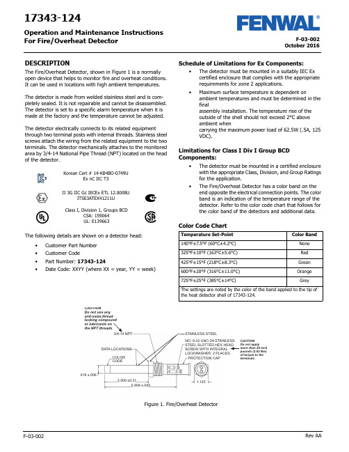
F-03-002October 2016F-03-002Rev AA17343-124Operation and Maintenance Instructions For Fire/Overheat DetectorDESCRIPTIONThe Fire/Overheat Detector, shown in Figure 1 is a normally open device that helps to monitor fire and overheat conditions. It can be used in locations with high ambient temperatures.The detector is made from welded stainless steel and is com-pletely sealed. It is not repairable and cannot be disassembled. The detector is set to a specific alarm temperature when it is made at the factory and the temperature cannot be adjusted.The detector electrically connects to its related equipmentthrough two terminal posts with internal threads. Stainless steel screws attach the wiring from the related equipment to the two terminals. The detector mechanically attaches to the monitored area by 3/4-14 National Pipe Thread (NPT) located on the head of the detector.The following details are shown on a detector head:•Customer Part Number •Customer Code•Part Number: 17343-124•Date Code: XXYY (where XX = year, YY = week)Schedule of Limitations for Ex Components:•The detector must be mounted in a suitably IEC Ex certified enclosure that complies with the appropriate requirements for zone 2 applications.•Maximum surface temperature is dependent onambient temperatures and must be determined in the finalassembly installation. The temperature rise of the outside of the shell should not exceed 2°C above ambient whencarrying the maximum power load of 62.5W (.5A, 125 VDC).Limitations for Class I Div I Group BCD Components:•The detector must be mounted in a certified enclosure with the appropriate Class, Division, and Group Ratings for the application.•The Fire/Overheat Detector has a color band on the end opposite the electrical connection points. The color band is an indication of the temperature range of the detector. Refer to the color code chart that follows for the color band of the detectors and additional data.Color Code ChartII 3G IIC Gc IECEx ETL 12.0008UITS03ATEX41211UClass I, Division 1, Groups BCDCSA: 159064UL: E139663Korean Cert # 14-KB4BO-0749UEx nC IIC T3Temperature Set-Point Color Band140°F±7.5°F (60°C±4.2°C)None 325°F±10°F (163°C±5.6°C)Red 425°F±15°F (218°C±8.3°C)Green 600°F±20°F (316°C±11.0°C)Orange 725°F±25°F (385°C±14°C)GreyThe settings are noted by the color of the band applied to the tip ofthe heat detector shell of 17343-124.NO. 8-32 UNC-2A STAINLESS STEEL SLOTTED HEX HEAD SCREW WITH INTEGRAL LOCKWASHER, 2 PLACES.3/4-14 NPTSTAINLESS STEELDATA LOCATIONSCOLOR CODEPROTECTION CAP.618 ±.0063.500 ±0.315.808 ±.0651.125the NPT threadsFigure 1. Fire/Overheat DetectorOctober 2016F-03-002 Rev AA2Specified data for the Fire/Overheat Detector is given in the table below .INSTALLATIONThis section gives the procedure to install the fire overheat detector .The fire/overheat detector must be attached to an IP 54 suitable/rated junction box with the applicable EquipmentGroup II and Category 3 for the installation. The box must have a 3/4 NPT opening to install the detector .The installer of the detector must supply a means to prevent non-permitted decrease of clearance per IEC60079-15, para-graph 6.7.Replacement parts must be the same part number as the part being replaced.Fastening of the fire detector is through the 3/4 NPT thread. Do not use any anti-seize thread locking compound or lubricant on the NPT threads. The installer must ensure that a proper ground connection is made to the IP 54 box-grounding termi-nal.Procedure1.Turn the detector clockwise into the related equipment’s 3/4 NPT opening a minimum of 5 full turns. Torque the detector to 20 lbf ft (27 Nm).2.Connect the related equipment’s system wiring to the detectors terminals with the No. 8-32 UNC-2A SS slotted hex head screws with integral washer . Make sure the wire connections do not touch each other . Torque the screws to a value between 20 and 25 lbf in. (2.26 and 2.82 Nm).3.Make sure that no objects touch the detector or can touch or damage it during usual system operation.4.Keep the detector free of contamination and unwanted materials. Refer to the Cleaning section.OPERATIONThe Fire/Overheat Detector’s outer shell is made of stainless steel that expands with an increase in temperature. It closely follows changes in the air temperature that surround it. Two inner struts, made of an alloy that expands at a lower rate than the outer shell, are sealed inside the outer shell. An overheat condition causes the shell to expand faster than the innerstruts. This makes the struts move together and make electrical connection through the contacts that are attached to the struts . The electrical connection of the contacts completes the circuit through the terminal posts on the end of the detector . Figure 2 shows a simplified diagram of the Fire/Overheat Detector oper-ation. When the shell and inner struts cool, the contacts open again.There are three conditions that can have an effect on the oper-ation of the detector , especially when a functional test of the detector is done. These conditions are:1.Temperature Overshoot: This condition can occur when the temperature of a detector increases far above its set-point range when heat is supplied too rapidly. This can cause the contacts to close before the specified tempera-ture range.2.Anticipation Effect: This condition causes the alarm circuit to close well before the alarm set-point. This condition is the result of the supply of high heat too rapidly.3.Temperature Undershoot: This condition occurs when the temperature of a detector decreases suddenly below its set-point range when made to cool too rapidly. The detec-tor should be air cool only.If possible, these conditions must be prevented, specially when tests of the detector are done.Figure 2. Detector Simplified DiagramSpecified Item or Function DataTemperature Range for Operation -50°F to +825°F (-45.5°C to +440.5°C)Electrical ContactRating 0.5 Ampere at 125VDCElectrical InterfaceConnection 2 each terminal posts with No. 8-32 UNC-2A Stainless Steel Slotted Hex HeadScrews with Integral LockwasherElectrical ConnectionTorque 25 lbf in. (2.8 Nm) maximum Electrical Connection Protection CapP/N RCL-10 (Vendor: Protective Closures Co., CAGE Code 99017)Dimensions See Figure 1ApprovalATEX approved for Zone 2, Category 3.Type of protection “nC”.Do not supply more than 25 lbf in. torque to the detector’s terminal screws or you can dam-age the detector . If the detector is damaged, you must discard it.Do not paint the detector or let paint from another source get on the detector or it will not operate correctly.READY OR STANDBY CONDITIONALARM OR OVERHEAT CONDITIONCONTACTS CLOSEDSHELL - HIGH EXPANSIONSTRUTS - LOW EXPANSION3October 2016F-03-002 Rev AA TestingThis section gives the equipment and procedures necessary to do tests of the detector and find if there is a malfunction.You must do a no-continuity test and an insulation resistance test to make sure the detector is serviceable.You must do a calibration verification test (or functional test) to make sure that the detector gives an alarm at the correct tem-perature.Testing EquipmentThe test equipment necessary to do the tests on the detector is given in the table below. You can use equivalent alternative items for those given in the table.Pretest InspectionBefore you test the detector , make sure that the detector’s visual inspection is acceptable. Refer to the Inspection section of this manual.No-Continuity TestDo the no-continuity test per the following procedure. Do the test at room temperature. If the test is unsatisfactory, replace the detector. Detector is not a repairable unit.Procedure1.Connect one lead of a digital multimeter (DMM) to one of the two terminals posts of the detector and the other lead of the DMM to the other terminal post. See the no-continuity test setup in Figure 3.2.With the DMM set to measure ohms (Ω) on the highest scale, read the resistance.3.The resistance value must read an open condition or infinite (∞).4.Disconnect the DMM from the detector .Figure 3. No-Continuity Test SetupInsulation Resistance TestDo the insulation resistance test per the following procedure. Do the test at room temperature. If the test is unsatisfactory, replace the detector . Detector is not a repairable unit.Procedure1.Connect one lead of a megohmmeter to the two terminal posts of the detector jumpered together. Connect the other lead of the megohmmeter to the detector shell. See the insulation resistance test setup in Figure 4.2.Set the megohmmeter to supply 500 VDC and measure the insulation resistance of the detector.3.The resistance must be 20 megohms (M Ω) or higher.4.Remove the power from the megohmmeter and disconnect the leads and jumper from the detector .Figure 4. Insulation Resistance Test SetupEquipment Item Range/Accuracy Manufacturer orSource Digital Multimeter , Fluke Model 77100VDC to 1000 VDC, 0.1Ω to 20M Ω,1% AccuracyFluke (CAGE 89536)Dry-Well Calibrator , Model 9141-A (used to verify calibra-tion set-point value)50 to 400°C ±0.5°CHart Scientific (CAGE 64841)Custom Insert, Model 3141-7 (for 9141-A, with one opening 0.629± 0.002in dia.)Not ApplicableHart Scientific (CAGE 64841)Power Source (to supply power to Dry-Well Calibrator 115 VAC, 50-60 Hz, 10 Amps or 230 VAC,5 Amps Get Locally Megohmmeter , Model 1867500 VDC, 20 M Ω andhigherQuad Tech (CAGE 0PK96)Prevent possible dangerous shock. Do not sup-ply power to the megohmmeter until it is con-nected to the detector .DETECTORDIGITALMULTIMETERDETECTORMEGOHMMETERJUMPEROctober 2016F-03-002 Rev AA4Calibration Verification Test1.The detector no-continuity test and insulationresistance test must be satisfactory before you do the calibration verification test.2.Make a test setup with the Model 9141 Dry-Well Calibrator. Make sure that you follow the safetyinstructions given in Section 3 of the Model 9141 Dry-Well Calibrator User Manual.3.Install the detector in the dry-well calibrator insert.4.Connect the dry-well calibrator test leads to the terminal posts on the detector.5.Connect the dry-well calibrator power cable to an applicable 115 or 230 VAC, 50-60 Hz power source.6.Follow the procedures in Section 7 of the Model 9141 Dry-Well Calibrator User Manual to make sure that the detector’s set-point is in limits.7.Record the temperature for each of three consecutive detector contact closures.8.Get an average of the three recorded values (add the three recorded values and divide by three). This is the detector set-point valve. The value must be the temperature shown on the detector ±25°F (±14°C).9.Remove the power from the dry-well calibrator and let the heater block and detector cool before you remove the detector under test.10.If the calibration verification test is unsatisfactory,replace the detector .DisassemblyThe fire/overheat detectors are hermetically sealed units. The detector cannot be disassembled.MAINTENANCECleaningThis section gives the procedure and materials necessary to clean the detector .MaterialsThe materials necessary to clean the detector are given in the table below. You can use equivalent alternatives for the items given in the table.Procedure1.Use a clean lint-free cloth wet with LPS Presolve solvent to clean the detector.2.Use nitrogen dry air at a maximum pressure of 30 psig (205 Kpa) to dry the detector .InspectionMake sure the detector is clean before you do the inspection. Refer to the Cleaning section.1.Examine the electrical connection terminals. Look for cracks or damage. If the connection terminals are damaged or cracked, discard the detector.2.Examine the electrical connection terminal screws. Look for damage to the screw threads and head. If damaged, replace the screws. Make sure the screws turn freely in the connection terminals. If the screws cannot be turned completely into the terminals, discard the detector.3.Examine the shell or tube of the detector. If there is a dent, scratch, or abrasion to the outer area, discard thedetector.Do not supply more than 25 lbf in. (2.82 Nm) torque to the screws in the detector terminals or you can damage the detector and it mustbe discarded.Be careful not to get burned from the hot heater block in the dry-well calibrator or the hot detector . The temperature can exceed 800°F or more.Be careful not to get burned by the hot heater block in the dry-well calibrator or the hot detector . The temperature can exceed 800°F or more.Materials Specification or Part No.Source Cloth, Clean Lint-free Solvent, LPS Presolve None 01428Get Locally LPS Laboratories (CAGE Code 66724)Nitrogen or Clean,Dry AirA-A-59503-1B1Get LocallyClean with solvents in an area that has good airflow. Do not clean near heat or open flame.While cleaning the detector , do not use abra-sive material or excessive force. This action will adversely affect the set point of the heat detector , compromising the accuracy of the detector .Be careful when you use compressed air or gas. Always point the flow away from person-nel. Compressed air or gas and the material moved by the air or gas pressure is dangerous and can cause injuries. Wear applicable eye protection.Fenwal Controls, Kidde-Fenwal Inc.400 Main Street Ashland, MA 01721Tel: 800-FENWAL-1Fax: 508-881-7619This literature is provided for informational purposes only. KIDDE-FENWAL, INC. assumes no responsibility for the product’s suitability for a particular application. The product must be properly applied to work correctly. If you need more information on this product, or have a particular problem or question, contact KIDDE-FENWAL, INC.F-03-002 Rev AA ©2016 Kidde-Fenwal, Inc.Storage and Movement1.Install a protection cap, P/N FS06-250099-071, over the electrical connection end of the detector.2.Make sure the detector has sufficient protection to prevent damage to the threads and outer shell.3.Put the detector in a container that is approved for storage.4.Keep the detector in a cool, dry area that has no contamination.5.If you must move the detector to another location, make sure it has sufficient protection to prevent damage.Fits and ClearancesTorque Values1.When you make electrical connection to the terminal posts, torque the screws to a value between 20 and 25 lbf. in (between2.26 and 2.28 Nm).2.When you install the detector, torque it to a value of 20 lbf. ft (27 Nm).Special Tools, Fixtures, Equipment and ConsumablesThe table below outlines the special tools, fixtures, equipment and consumable items needed to maintain the detector .Also provided are the vendors and the Commercial and Government Entity [CAGE] code.Do not torque the terminal post screws to a value more than 25 lbf in. or you can damage the detector . If the detector is damaged, you must discard it.DescriptionPart NumberVendorsRecommended SourceMultimeter Model 77Fluke Corporation 6920 Seaway BoulevardP .O. Box 9090Everett, WA 98206Fluke (CAGE 89536)Megohmmeter , 500 VDC, 20 M and higherModel 2867Quad Tech Inc.5 Clock Tower Place 210 East Maynard, MA 01754-2530Quad Tech (CAGE 0PK96)Dry-Well Calibrator Model 9141-A Hart Scientific799 E. Utah Valley Drive American Fork, Utah 84003-9775Hart Scientific (CAGE 64841)Customer Insert(used with Dry-Well Calibrator)Model 3141-7Cleaner/Degreaser , LPS Pre-Solve01428LPS Laboratories, Inc 4647 Hugh Howell Rd Tucker , GA 30085-5052LPS Laboratories (CAGE 66724)Protection Cap RCL-10Protective Closures Co., Inc.DBA Caplugs LLC Div. Caplugs Division2150 Elmwood Avenue Buffalo, NY 14207-1984Protective Closures Co.(CAGE 99017)Torque Screwdriver , 20 to 25 lbf in.None Specified Commercially Available Commercially Available Torque Wrench, 20 lbf ft.None SpecifiedCommercial AvailableCommercially AvailablePower Source, 115 VAC, 50-60 Hz, 10 Amps or230 VAC, 5 Amps(Necessary for Dry-Well Calibrator)None Get Locally Get Locally Cloth, Lint free None Get Locally Get Locally Nitrogen or Clean, Dry AirA-A-59503-1B1Get LocallyGet LocallyNote: All vendors are located in the United States.。
艾默生 FLUXUS G532CA利用超声波对压缩空气进行非侵入式体积流量测量 说明书

FLEXIM GmbHBoxberger Str. 412681 BerlinGermany电话: +49 (30) 93 66 76 60传真: +49 (30) 93 66 76 80保留不经事先通知变更的权利。
保留出错的权利。
FLUXUS 是 FLEXIM GmbH 的注册商标。
网址: 电子邮件:***************Copyright (©) FLEXIM GmbH 2023利用超声波对压缩空气进行非侵入式体积流量测量TSFLUXUS_G532CAV1-0-1ZH_Leu, 2023-06-12FLUXUS G532CA 技术规格2023-06-12, TSFLUXUS_G532CAV1-0-1ZH_Leu2功能. . . . . . . . . . . . . . . . . . . . . . . . . . . . . . . . . . . . . . . . . . . . . . . . . . .3测量原理. . . . . . . . . . . . . . . . . . . . . . . . . . . . . . . . . . . . . . . . . . . . . . . . .3计算体积流量. . . . . . . . . . . . . . . . . . . . . . . . . . . . . . . . . . . . . . . . . . . . . . .3计算标准体积流量. . . . . . . . . . . . . . . . . . . . . . . . . . . . . . . . . . . . . . . . . . . . .4声程数. . . . . . . . . . . . . . . . . . . . . . . . . . . . . . . . . . . . . . . . . . . . . . . . . .4典型测量布局. . . . . . . . . . . . . . . . . . . . . . . . . . . . . . . . . . . . . . . . . . . . . . .5测量变送器. . . . . . . . . . . . . . . . . . . . . . . . . . . . . . . . . . . . . . . . . . . . . . . .6技术参数. . . . . . . . . . . . . . . . . . . . . . . . . . . . . . . . . . . . . . . . . . . . . . . . .6尺寸. . . . . . . . . . . . . . . . . . . . . . . . . . . . . . . . . . . . . . . . . . . . . . . . . . .72"管道安装组件 (可选). . . . . . . . . . . . . . . . . . . . . . . . . . . . . . . . . . . . . . . . . .8存储. . . . . . . . . . . . . . . . . . . . . . . . . . . . . . . . . . . . . . . . . . . . . . . . . . .8端子分配. . . . . . . . . . . . . . . . . . . . . . . . . . . . . . . . . . . . . . . . . . . . . . . . .9传感器. . . . . . . . . . . . . . . . . . . . . . . . . . . . . . . . . . . . . . . . . . . . . . . . . 10技术参数. . . . . . . . . . . . . . . . . . . . . . . . . . . . . . . . . . . . . . . . . . . . . . . . 10传感器固定件. . . . . . . . . . . . . . . . . . . . . . . . . . . . . . . . . . . . . . . . . . . . . . 12传感器的耦合材料. . . . . . . . . . . . . . . . . . . . . . . . . . . . . . . . . . . . . . . . . . . . 12阻尼垫. . . . . . . . . . . . . . . . . . . . . . . . . . . . . . . . . . . . . . . . . . . . . . . . . 13连接系统. . . . . . . . . . . . . . . . . . . . . . . . . . . . . . . . . . . . . . . . . . . . . . . . 14接线盒. . . . . . . . . . . . . . . . . . . . . . . . . . . . . . . . . . . . . . . . . . . . . . . . . 15技术参数. . . . . . . . . . . . . . . . . . . . . . . . . . . . . . . . . . . . . . . . . . . . . . . . 15尺寸. . . . . . . . . . . . . . . . . . . . . . . . . . . . . . . . . . . . . . . . . . . . . . . . . . 152"管道安装组件. . . . . . . . . . . . . . . . . . . . . . . . . . . . . . . . . . . . . . . . . . . . . 16温度传感器. . . . . . . . . . . . . . . . . . . . . . . . . . . . . . . . . . . . . . . . . . . . . . . 17技术参数. . . . . . . . . . . . . . . . . . . . . . . . . . . . . . . . . . . . . . . . . . . . . . . . 17固定. . . . . . . . . . . . . . . . . . . . . . . . . . . . . . . . . . . . . . . . . . . . . . . . . . 17接线盒. . . . . . . . . . . . . . . . . . . . . . . . . . . . . . . . . . . . . . . . . . . . . . . . .18压力变送器 (可选). . . . . . . . . . . . . . . . . . . . . . . . . . . . . . . . . . . . . . . . . . . 20技术参数. . . . . . . . . . . . . . . . . . . . . . . . . . . . . . . . . . . . . . . . . . . . . . . . 20技术规格 FLUXUS G532CA3TSFLUXUS_G532CAV1-0-1ZH_Leu, 2023-06-12功能测量原理超声波传感器安装在管道上,该管道完全充满流体。
德国菲索AFRISO烟气分析仪中文使用说明书 Bluelyzer ST -B20
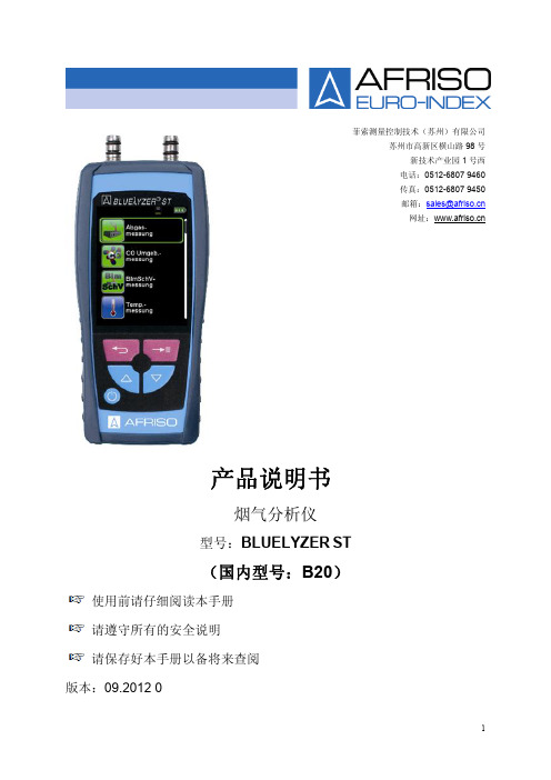
2.3 安全操作 B20 烟气分析仪采用了最先进的技术工艺,测量标准符合 BlmSchV(德国联邦第一 排放法案)。每台仪器在出厂之前都会接受严格的性能和安全测试。
7
3.1 功能图解
1 返回/取消/直接存储键 2 向上移动键 3 开/关机键 4 保护套 5 向下移动键 6 确认/输入键 7 显示屏 8 抽力测量接口(选配) 9 扬声器 10 充电接口 11 红外打印接口 12 SD 卡插槽 13 烟气测量接口 14 烟气温度插口 15 环境温度插口
3.2 随机配置 产品包括:烟气分析仪器,磁性保护套,标准烟气采样探枪(带冷凝过滤装置), 环境温度传感器,备用 Teflon 过滤膜(耗材更换),充电器。
仪器开启后会有一个 30 秒的自动校准过程
当 CO 浓度值超过最大量程时(> 6000 ppm),抽气泵 将自动关闭以保护传感器不被中毒。当 CO 浓度下降 到量程范围内,CO 传感器复位,则抽气泵自动开启, 测量重新开始。
通过采样探枪采集烟气,可以配置“一点采样”探针 也可以“多点采样”探针,满足您的不同需求
警告
电击危险
请勿用仪器或烟气探针接触、甚至测量带电物体。
2.4 人员资格 该产品只能由经过专业培训、有资质的人员进行安装、调试、操作、维修、废弃及 其他相关处理。 产品的电气部分也只能由有资质的电工按照地方和国家的法律法规来执行。
6
2.5 校准 建议烟气分析仪由厂方授权或有资质的相关机构进行传感器的校准。
#4脱硫电动头(扬修非侵入式2SA3说明书)
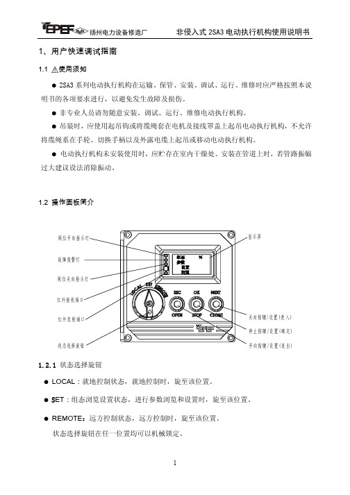
1.4 遥控器 1.4.1 性能参数
电源 使用距离
3 节 1.5VDC 7#电池 ≤3 米(距执行机构显示窗口)
1.4.2 按键功能 取址键: 获取当前需要控制的一个执行机 构的通讯地址; 状态切换键: 就地控制、远方控制、参数 浏览设置三种状态选择切换; 取消键: 退出当前状态; 开向键: 等同于 ESC(OPEN)键的功能;
●遥控器红外传送窗口处有红、绿灯各一,其状态同操作面板红、绿灯。
●每台执行机构的地址是唯一的。
●若遥控器不能及时获取到地址或操作距离减小,请更换电池,长期不使用时,请取出遥 控器中电池。
1.5 快速设置(初次使用)
按照接线罩盖内电气接线图正确接线,检查无误后接通电源;若电动执行机构控制参 数无需改变,用户应根据阀门实际情况设定阀门的开向、关向终端位置。
转矩控制器开关在输出轴的两个旋转方向上各有一只。每台电动执行机构的设置转矩
及转矩最小/最大范围出厂时均已按用户订单的要求进行调整设定,如用户订单无要求则
在出厂时设定在最小转矩上。 如果需要,用户也可以自己在转矩范围内进行调整设定,调整时只要旋转图 1 中的件
4.1(4.2)即可:当电动执行机构为右旋时(出厂默认值),调整调节件 4.1 为开向转矩,顺
●可选方式:行程限位、转矩限位 ●开向限位、关向限位可分别选择
参数设置 基本参数 中间位置1
00.0%
*** %
SET LOCAL REMOTE ESC OK NEXT
OPEN STOP CLOSE
参数设置 基本参数 反馈值斜率
正
00.0% 负
SET LOCAL REMOTE ESC OK NEXT
1.2.1 状态选择旋钮 ● LOCAL:就地控制状态,就地控制时,旋至该位置。 ● SET:组态浏览设置状态,进行参数浏览和设置时,旋至该位置。 ● REMOTE:远方控制状态,远方控制时,旋至该位置。 状态选择旋钮在任一位置均可以机械锁定。
ISA3系列说明书

No.PS※※-OMR0001CN-D
产品特征
能够检出检测面与工件间的缝隙量(0.02 mm~0.15 mm、0.05 mm~0.30 mm)。 在主画面上通过 ON(绿色)/OFF(橙色)显示是否已到位。(出厂时设定的场合) 子画面可以通过水平仪显示检测面与工件间的测定距离的参考基准。 是避免伤到工件的非接触型位置传感器。
配管规格 供给侧:Rc1/8
G 检出侧:φ4快插※1
φ6快插※2 F 供给侧:G1/8※3
检出侧:G1/8※3
输出规格
N
NPN输出
P
PNP输出
无记号 M
压力值的单位规格
带单位切换功能※4 固定SI单位※5
连数
1
1连
2
2连
3
3连
4
4连
5
5连
6
6连
可选项 1(电缆)
直线式 电缆※6 无记号
直角形 电缆※6 L
②请具有充分的知识和经验的人员使用本产品。 在此所述产品若误操作会损害其安全性。 机械·装置的组装、操作、维修保养等作业请由具有充分知识和经验的人进行。
③请务必在确认机械・设备的安全之后,再进行产品的使用和拆卸。 1.请在确认已进行了移动体的落下防止对策和失控防止对策之后再进行机械·设备的使用和维护。 2.请在确认已采取上述安全措施,并切断了能量源和设备电源以保证系统安全的同时,确认和理解设备上产 品个别注意事项的基础上,进行产品的拆卸。 3.重新启动机械·设备时,请对意外动作·误操作采取预防措施。
键盘锁定(设定密码)
49
维护
50
故障一览表
51
错误显示 ················· 52
供给压力与显示的关系 ··········· 52
3M高级光线控制膜(ALCF-A2+、ALCF-A3+和A5+39(H))产品说明说明书

3M™ Advanced Light Control Film AutomotiveALCF-A2+ALCF-A3+ALCF-A5+39ALCF-A5+39HProduct Description3M™ Advanced Light Control Film (ALCF-A2+,ALCF-A3+ and A5+39(H)) constrains light exitingfrom liquid crystal displays and interior light sources.This effect minimizes reflections on the windscreen orside glass.Construction/Performance3M Display Materials & Systems DivisionTechnical Data 2021Automotive Environmental Testing*for 3M ALCF-A5+39 and 3M ALCF-A5+39HAutomotive Display – Recommended Solutions3M™ Dual Brightness Enhancement Film (DBEF)3M™ Enhanced Specular Reflector (ESR)*example data shown in plot from ALCF-A3+3M™ Brightness Enhancement Film (BEF)3M™ Advanced Light Control Film (ALCF)3M™ Advanced Light Control Film ComparisonFull Instrument Cluster or Center Stack Sample Performance (Single BEF)559.2 > 745.1 373.3 187.3 < 1.4559.3> 745.1373.4187.6< 1.8602.7> 803.1402.4202< 1.6Note: Samples measured on a 12.3" IPS display with White Reflector/Light Guide/Diffuser/BEF3-t-155n/ALCF-AX+ film stack Axial Gain with reference diffuser only.Partial Instrument Cluster Sample PerformanceALCF-A2+ALCF-A3+ALCF-A5+39H661 > 881 441 221 < 1631.9> 842.1421.6211.4< 1.2711.3> 948.1474.5237.7< 0.9Note: Samples measured on a 12.3" IPS display with White Reflector/Light Guide/Diffuser/Crossed BEF3-t-155n/ALCF-AX+ film stack Axial Gain with reference diffuser only.3M Demo – Example Angular Luminance DataMeasurement100-80-60-40-20204060800-80-60-40-2020406080200300400500600700800900100200300400500600700800900A2+A3+A5+39A2+A3+A5+39Vertical Cross Section Horizontal Cross Section Optical Stack = Diffuser Sheet/3M™ BEF3-T-155n/Light Control Film Sample Optical Stack = Diffuser Sheet/3M™ BEF3-T-155n/Light Control Film SampleStorage and HandlingProduct must be stored flat, in its original 3M packaging, out of sunlight, and in a clean, dry (relative humidity between 30% and 60%) area that is maintained at a temperature between 10°C and 30°C. Avoid applying pressure to, or resting objects on, the product to prevent marking, denting or deforming. Hold product by the edges to prevent soiling of the view area and wear gloves to prevent fingerprints or nail marks. Do not slide the product.Limited Warranty3M warrants that each Product will conform to our Customer Quality Standard (the “3M Warranty”) for12 months after 3M’s Product shipment (“Warranty Period”). Any engineering or technical information, recommendations, installation instructions, jumbo delivery standards, certificates of analysis, and other information or materials relating to Products (“Other Product Information”) is provided for the Product buyer’s convenience and is not warranted. 3M will have no obligations under the 3M Warranty with respect to any Product that has been: (a) not stored, handled, or transported in accordance with this Warranty or Other Product Information; or (b) modified or damaged by anyone other than 3M.3M Display Materials & Systems Division3M Center, Building 235-1E-54 St. Paul, MN 55144-1000 U.S.A. Phone 1-800-3M HELPS Web /displayfilms 3M is a trademark of 3M Company.All other trademarks herein are the property of their respective owners.© 3M 2021. All rights reserved. dz29888Measurement (continued)。
COD-203A(S)说明书

-6-
COD-203A 型
阅读指南
阅读指南
请根据您的用途阅读本说明书的相应部分,如了解产品概要或开始使用产品,具体内容如下 图所示。圆圈中的数字为参考章节的阅读顺序。
章节
目的
重物
需使用地脚螺栓等固定该产品。该产品是重量约 200 公斤的重物,如果翻倒可能导致 损伤或身体伤害。
拆卸和改装
不得在本说明书说明范围以外拆卸或改装该产品,否则该产品可能损坏。
警告标签丢失
如果该产品随附的警告标签难以阅读,请您通过当地的销售代理或销售办事处订购新的标 签,并将标签粘贴在原来的位置。
(3) 使用说明书时的注意事项
●阅读指南 ··················································································································7
1. 操作面板功能·······························································································13
(2) 保修限制 保修范围不包括下列情况。 (a) 因超出本产品技术规格和说明书记载用途和使用方法而导致的直接或间接故障或损坏。 (b) 因不可抗力而导致的直接或间接故障或损坏,包括但不限于天灾、自然灾害(地震、风暴和水灾)、雷击、 火 灾 、 意 外 事 故 、 电 压 异 常 、 盐 蚀 、 气 体 损 坏 、 劳 工 动 乱 、 战 争 ( 无 论 宣 战 与 否 )、 恐 怖 袭 击 、 内 乱 或 任 何 政府管制行为。 (c) 未经 DKK-TOA 授权的任何修理或改装而导致的故障或损坏。 (d) 购买后因与 DKK-TOA 无关的运输、搬运或掉落而导致的故障或损坏。 (e) 电极和易损件(产品部件的保修期短于主机保修期时,则优先依照该部件的保修期进行保修。自生产之日起 6 个月后,用户如需任何部件,请咨询 DKK-TOA 或经销商)。 (f) 使用非 DKK-TOA 提供的易损件、部件或软件而导致的故障或损坏。 (g) 使用非 DKK-TOA 提供的连接设备而导致的故障或损坏。 (h) 存储于该产品的数据、设置、程序或软件出现与 DKK-TOA 无关的丢失现象。 (i) 如果购买者或用户指定将 DKK-TOA 以外的任何产品与 DKK-TOA 产品相结合或组合使用 (*1),则保修范围 只限于 DKK-TOA 产品。 (j) 未按照 DKK-TOA 提供的说明书进行适当保养的所有产品。 (k) 产品无铭牌(不包括经证实由 DKK-TOA 交付的产品)。
梅思安说明书
Ultima-X系列气体探测器使用说明书(请以原版说明书为准)中美合资无锡梅思安安全设备有限公司WUXI MSA SAFETY EQUIPMENT CO. LTD.重要的警告本说明书只是对该类仪表作简要的介绍,具体使用说明请按原版英文说明书为准。
任何负责或将要负责安装、使用或维修本产品的人员都必须仔细阅读本说明书。
象任何复杂的设备一样,只有按照制造厂家的说明与要求去安装、使用及维修,才能使本仪表按设计的性能要求去年工作,否则,仪表将不能正常工作而致使依靠此仪表来保障安全的愿望无法实现,甚至发生更为严重的伤亡事故。
如果不按照本手册的说明去安装、使用及维修本仪表,无锡梅思安公司对本产品所作的保证将是无效的。
因此,请遵守本手册说明以保障你本人及员工的安全,欢迎用户在使用本产品之前写信或打电话来询问有关使用或维修方面的信息。
1注意事项1、本手册所叙述的变送器应按照产品标签、注意事项、警告等项说明(并仅限在指明的范围内)去安装、操作和维修保养。
2、为防止在危险环境下引燃起爆,当接通电源时探测器的防爆盒盖务必密闭。
如需打开盒盖维修或标定,先要确认环境空气中无可燃性气体存在,直至关上盒盖。
3、探测器设计用来检测空气中的可燃性气体、毒气、氧气或其蒸汽浓度,而不能测定水汽中或惰性气体中或严重缺氧环境中的可燃性气体与蒸汽浓度。
4、探测器探头探测器隔爆片上不能被粘污或涂漆。
如在安放探测器的场所进行喷漆,须注意确保探测器入口处的粉末冶金隔爆片上不能粘有漆,否则,漆会阻碍被监测的气体扩散进入探测器。
安装时探测器朝下并离地面至少0.3M,以方便检修及标定,要杜绝雨水的滴入和地面水的溅入。
5、确保探测器正常工作的唯一方法是用已知浓度的气体对探测器进行标定检查,因此标定检查应作为此系统日常检查工作的一部分。
6、探测器的电源电压为7~30VDC,推荐工作电压为24VDC。
超过30VDC的电压将导致仪表的永久性损坏!7、在进行本手册所介绍的操作和保养时,只可以使用真正无锡梅思安公司的配件,否则,可能会严重影响仪表性能。
成都新为诚科技有限公司微型泵两用调节阀F2A系列产品说明书

微型泵两用调节阀F2A系列产品说明书(Ver.2021.9.1)版权所有©成都新为诚科技有限公司2020。
保留一切权利。
非经本公司书面许可,任何单位和个人不得擅自摘抄、复制本文档内容的部分或全部,并不得以任何形式传播。
商标声明商标为成都新为诚科技有限公司的商标。
本文档提及的其他所有商标或注册商标,由各自的所有人拥有。
注意您购买的产品、服务或特性等应受成都新为诚科技有限公司相关合同和条款的约束,本文档中描述的全部或部分产品、服务或特性可能未包含在您的购买或使用范围之内。
除非合同另有约定,成都新为诚科技有限公司对本文档内容不做任何明示或默示的声明或保证。
由于产品版本升级或其他原因,本文档内容会不定期进行更新。
除非另有约定,本文档仅作为使用指导,本文档中的所有陈述、信息和建议不构成任何明示或暗示的担保。
成都新为诚科技有限公司地址:成都市武侯区武侯大道顺江段77号汇点广场2座905-906邮编:610045网址:电话:************、66165538手机(微信同号):153****8198、133****9186天猫旗舰店:https:///微信公众号:前言摘要本文为微型泵两用调节阀F2A系列产品相关说明,用于指导相关技术人员了解该产品特性。
读者对象本文档适用于产品使用人员和相关技术人员。
您非常了解您的产品,并对所需微型泵的相关参数、规格大小等信息有明确概念。
关键字技术参数、操作说明、安装说明版本记录目录1产品外观及特点 (3)1.1产品外观 (3)1.2产品特点 (4)2技术参数 (6)2.1关键参数 (6)2.2原理 (7)2.3禁忌 (7)3安装说明 (8)3.1安装方向性 (8)3.2安装方式 (10)3.3拆卸和更换直通管或三通管 (11)4调节示意图 (12)4.1微型阀如何调节流量连接方式 (12)4.2微型阀调负压正压时连接方式 (14)5接头尺寸图 (18)6注意事项 (20)7微型阀F2A不同用途时安装尺寸图 (21)7.1F2A-3B7外形尺寸(单位:mm) (21)7.2F2A-3B7外形尺寸(单位:mm) (22)7.3F2A-3B11外形尺寸(单位:mm) (23)7.4F2A-3B11外形尺寸(单位:mm) (24)7.5F2A-3B13外形尺寸(单位:mm) (25)7.6F2A-3B13外形尺寸(单位:mm) (26)1产品外观及特点1.1产品外观1.2产品特点1.新为诚两用微型针型阀F2A系列,以品质气动元件厂家SMC阀芯为核心部件,搭配精密机加工直通接头或三通接头,与微型泵配合,既可以做微型流量阀调节流量,又可以做微型调压阀,调节负压、正压;2.新为诚微型针型阀F2A系列——“接头全能”;既可以接软管:接头采用2级或3级宝塔气嘴,兼容多种内径软管,内径3-6mm或5-10mm,弹性较好的软管都可以直接使用;又可以接Rc1/8螺纹硬管或外径8mm快插管;总有一款适合您!3.F2A-3B13微型针型阀,较独特的接口设计(配备Rc1/8内螺纹,可直接接外螺纹硬管!而行业微型针型阀多数配备得是接软管的宝塔接头),还可定做PC6/PC8的不锈钢快换接头,连接常用的外径6/8mm的快插管,迅速搭配气路。
机械类产品使用说明书的翻译

98现代交际·2019年6期作者简介:赖兴娟,内蒙古大学外国语学院2017级硕士研究生,研究方向:俄语笔译。
机械类产品使用说明书的翻译赖兴娟(内蒙古大学 内蒙古 呼和浩特 010000)摘要:机械类产品使用说明书是向用户介绍产品用途、工作原理、保养和维护等的一种书面文件。
近年来,随着中俄贸易的不断发展,两国之间机械类产品的进出口活动也日益频繁。
因此,机械类产品说明书的翻译作为产品信息交流的桥梁也越来越不可或缺。
本文以《2SA3系列电动执行机构使用说明书》《蒸浓器技术章程》和《JQH 系列气动绞车使用说明书》为例,归纳出机械类产品使用说明书的翻译特点,总结了机械类产品使用说明书的翻译过程,探讨了此类文本的翻译方法与技巧。
希望本文能为今后此类文本的翻译提供一些参考。
关键词:机械类产品使用说明书 科技语体 翻译方法 翻译技巧中图分类号:H315.9 文献标识码:A 文章编号:1009-5349(2019)06-0098-03一、机械类产品使用说明书的翻译特点机械类产品说明书作为科技文体,其目的是向大众传播科学知识。
因此,科技翻译要以准确、严谨为第一要旨。
科技文体通常承载着大量信息,要想使读者在短时间内科学地选取自己所需要的有效信息,就需要语言简练、逻辑明确。
因此,机械类产品说明书需要结合“准确”“严谨”和“简练”的特点来进行翻译。
1.词义单一、意义明确运用到科技语体中的词汇,既有单义词,又有多义词。
但在科技文章中,为避免理解歧义,通常使用同一词语来表示同一概念。
例如:установка本身为多义词,意为“安装”“设置”,在《非侵入式2SA3电动执行机构使用说明书》中,为避免歧义,将“安装”译为установка,而将“设置”译为настройка。
2.大量使用前置词前置词的使用可以使句子逻辑更加清晰、语言更加简练,在科技语体,尤其是在机械产品使用说明书中成为必不可少的一部分。
如:При(在……况下),Для(为了),В связи с(由于), В соответствии с(根据、按照),В качестве(作为)等。
