KPF020D02中文资料
阿特拉斯空压机说明书
4.2 控制面板...........................................................................75
4.3 所用图标...........................................................................76
2
概述.......................................................................10
2.1 简介...............................................................................10 2.2 气流...............................................................................14 2.3 润滑油系统.........................................................................17 2.4 冷却系统...........................................................................18 2.5 冷凝水系统(在 PACK 机组上为可选件)...............................................19 2.6 调节系统...........................................................................21 2.7 电气系统...........................................................................22 2.8 电气原理图.........................................................................23 2.9 空气干燥机..................................30
康诚机组产品使用说明书
第一章安全手则操作发电机之前,需先阅读操作手册,并且熟悉你的设备,只有正确地操作并且维护设备,才能够达到安全、有效的运转。
许多意外伤害产生是由于没有遵循基本规则和安全守则。
燃油和油气非常容易起火●燃油管路必需有足够的安全保证,而且不会渗漏。
和发动机连接处必须用合格而防震的管路,此管路不可使用铜管;●确定所有燃油进油管路皆有控制阀;●检修蓄电池时不可吸烟,铅酸蓄电池会产生爆炸性的氢气,如果有电弧或吸烟的火花会立即发生爆炸。
发动机的排气有致命性●确保机组的通风系统顺畅;●提供一个适当的排烟系统来排放废气,经常目视或耳听检查排气系统是否泄露,并依照保养时间表,确定排气管固定安装好。
转动的机件会使人员重伤或死亡●在起动前的检查保养时,应断开蓄电池线,以防意外起动;●起动之前,应确保零部件的安全,检查其是否紧固牢靠,支架、管夹是否定位,风扇、传动皮带等转动件的护罩是否护好;电击可以使人员受伤或死亡●在维护和保养机组时,应关闭电力电源;在电气设备周围的金属或钢筋结构的地板上,应放置干燥的木版并垫上橡胶绝缘垫;●不允许穿潮湿的衣服和鞋子或皮肤潮湿时处理电气故障;●电压超过36V时,会造成人员伤亡或死亡。
不要擅自修改电气线路;●开关断开时,必须贴上明显标识,防止其他人员误操作,导致人员或设备发生事故;●发电机组不能直接连接到市电供电系统上,否则会造成设备和电力系统损坏或烧损。
安全预防:●在受压的情况下,发动机冷却液的沸点要比一般普通水高,在发动机运转时,千万不要打开水箱或热交换器的压力盖。
检修发动机时,如果需要打开压力盖,必须先让发动机冷却,使压力释放出来后,再打开压力盖;●柴油机内含有导致癌症及其其他有害物质,当检查机组加油或泄油时,不要吸入柴油;●润滑油内含有导致癌症及其其他有害物质,当检查机组加油或泄油时,不要吸入润滑油;●发动机附近不要放置纸屑、布条等等,防止杂物引起火灾;●发电机组上不要放置所有不必要的油脂和润滑油;●发动机排放的废气会导致癌症或其他上海,不要吸入废气,或将废气排入室内;●发电机组和机房应保持清洁,不应放置杂物。
浦发拓温暖系统热泵分系列产品说明书
Product DataSplit System Heat Pump4TWR4018G1000A Array 4TWR4024G1000A4TWR4030G1000A4TWR4036G1000A4TWR4042G1000A4TWR4048G1000A4TWR4060G1000AN o t e:“Graphics in this document are for representationonly.Actual model may differ in appearance.”April202022-1765-13J-E NProduct Specifications(a)Certified in accordance with the Unitary Air-conditioner equipment certification program which is based on AHRI standard210/240.(b)Calculated in accordance with N.E.C.Only use HACR circuit breakers or fuses.(c)Reference the outdoor unit ship-with literature for refrigerant piping length and lift guidelines.Reference the refrigerant piping software pub#32-3312-xx or refrigerant piping application guide SS-APG006-xx for long line sets or specialty applications(xx denotes latest revision).(d)The outdoor condensing units are factory charged with the system charge required for the outdoor condensing unit,ten(10)feet of tested connecting line,and the smallest rated indoor evaporative coil match.Always verify proper system charge via subcooling(TXV/EEV)or superheat(fixed orifice)per the unit nameplate.(e)25,30,35and50foot linesets available.For a complete listing of lineset options available from equipment or supply stores,refer to the Trane Residentialand Light Commercial Product Handbook.P r o d u c t S p e c i f i c a t i o n s(a)Certified in accordance with the Unitary Air-conditioner equipment certification program which is based on AHRI standard210/240.(b)Calculated in accordance with N.E.C.Only use HACR circuit breakers or fuses.(c)Reference the outdoor unit ship-with literature for refrigerant piping length and lift guidelines.Reference the refrigerant piping software pub#32-3312-xx or refrigerant piping application guide SS-APG006-xx for long line sets or specialty applications(xx denotes latest revision).(d)The outdoor condensing units are factory charged with the system charge required for the outdoor condensing unit,ten(10)feet of tested connecting line,and the smallest rated indoor evaporative coil match.Always verify proper system charge via subcooling(TXV/EEV)or superheat(fixed orifice)per the unit nameplate.(e)25,30,35and50foot linesets available.For a complete listing of lineset options available from equipment or supply stores,refer to the Trane Residentialand Light Commercial Product Handbook.Accessory Description and UsageA n t i-S h o r t C y c l e T i m e r—Solid state timing device that prevents compressor recycling untilfive(5)minutes have elapsed after satisfying call or power e in area withquestionable power delivery,commercial applications,long lineset,etc.E v a p o r a t i o n D e f r o s t C o n t r o l—SPST Temperature actuated switch that cycles the condenseroff as indoor coil reaches freeze-up ed for low ambient cooling to30°F with TXV.R u b b e r I s o l a t o r s—Five(5)large rubber donuts to isolate condensing unit from transmittingenergy into mounting frame or e on any application where sound transmission needs tobe minimized.H a r d S t a r t K i t—Start capacitor and relay to assist compressor motor e in areas withmarginal power supply,on long linesets,low ambient conditions,etc.E x t r e m e C o n d i t i o n M o u n t K i t—Bracket kits to securely mount condensing unit to a frame orpad without removing any e in areas with high winds,or on commercial roof tops,etc.A H R I S t a n d a r d C a p a c i t y R a t i n g C o n d i t i o n sAHRI Standard210/240Rating Conditions1.Cooling80°F DB,67°F WB air entering indoor coil,95°F DB air entering outdoor coil.2.High Temperature Heating47°F DB,43°F WB air entering outdoor coil,70°F DB air enteringindoor coil.3.Low Temperature Heating17°F DB air entering indoor coil.4.Rated indoor airflow for heating is the same as for cooling.A H R I S t a n d a r d270R a t i n g C o n d i t i o n s—(Noise rating numbers are determiend with the unit incooling operations.)Standard Noise Rating number is at95°F outdoor air.Model NomenclatureOutdoor Units3 = 134 = 145 = 15Schematic DiagramsFigure 1. 1.5,2.0,2.5&3.5TonModelsFigure 2. 1.5,2.0,2.5&3.5TonModelsS c h e m a t i c D i a g r a m sFigure 3. 3.0TonS c h e m a t i c D i a g r a m sFigure 4.4and 5TonModelsS c h e m a t i c D i a g r a m sFigure 5.4and 5TonModelsS c h e m a t i c D i a g r a m sOutline DrawingMechanical Specification OptionsG e n e r a lThe outdoor condensing units are factory charged with the system charge required for theoutdoor condensing unit,ten(10)feet of tested connecting line,and the smallest rated indoorevaporative coil match.This unit is designed to operate at outdoor ambient temperatures as highas115°F.Cooling capacities are matched with a wide selection of air handlers and furnace coilsthat are AHRI certified.The unit is certified to UL1995.Exterior is designed for outdoorapplication.C a s i n gUnit casing is constructed of heavy gauge,galvanized steel and painted with a weather-resistantpowder paint finish.The corner panels are prepainted.All panels are subjected to our1,000hoursalt spray test.R e f r i g e r a n t C o n t r o l sRefrigeration system controls include condenser fan,compressor contactor and low and highpressure switches.A factory supplied,field installed liquid line drier is standard.C o m p r e s s o rThe compressor features internal over temperature and pressure protection.Other featuresinclude:Centrifugal oil pump and low vibration and noise.C o n d e n s e r C o i lThe outdoor coil provides low airflow resistance and efficient heat transfer.The coil is protectedon all four sides by louvered panels.L o w A m b i e n t C o o l i n gAs manufactured,this system has a cooling capacity to55°F.The addition of an evaporatordefrost control permits operation to40°F.The addition of an evaporator defrost control with TXVpermits low ambient cooling to30°F.The addition of the BAYLOAM107A low ambient kit permits ambient cooling to20°F.T h e r m o s t a t s—Cooling only and heat/cooling(manual and automatic change over).Sub-base tomatch thermostat and locking thermostat cover.22-1765-13J-EN11Trane-by Trane Technologies(NYSE:TT),a global innovator-creates comfortable,energy efficient indoor environments for commercial and residential applications.For more information,please visit or .The AHRI Certified mark indicates Trane U.S.Inc.participation in the AHRI Certification program.For verification of individual certified products,go to ahridirectory. org.Trane has a policy of continuous data improvement and it reserves the right to change design and specifications without notice.We are committed to using environmentally conscious print practices.22-1765-13J-EN28Apr2020Supersedes22-1765-13H-EN(October2019)©2020Trane。
小家电产品及维修培训课件

不通电故障
为什么会 不通电?
主要故障点:
1、配线
2、底部限温组件故障 3、电源电路板 4、电源线坏 5、插座坏 6、电热盘组件 7、控制电路板
饭煮不熟
主要故障点:
1、磁钢限温器 2、电热盘变形 3、内锅变形 4、电源电路板 5、主温控器异常 6、煮粥拨钮 7、外锅坏 8、杠杆故障 9、控制电路板
➢ 原因:无法检测到锅,不能执行加热 ➢ 状态:无法加热、停机 ➢ 分析思路: ①、主板:同步电路、IGBT驱动、振荡电路、比较器故障 ②、显示板:排线接触不良、单片机故障
测试点
比较器
过流电路
谐振电容
滤波电容
风机、E6故障
➢ 原因:风机转速异常 ➢ 状态:无法持续加热 ➢ 分析思路: ①、显示板:显示板信号、排线接触不良 ②、主板:驱动三极管击穿、风机卡死、风机烧坏
硅晶板系列
无机陶瓷
三重方式
NDYH-21a
NDYH-23B
快热炉系列
断电复位
独立增湿
NDA-24
暖风机系列
PTC陶瓷
自动调节功率
NTFD-20B
NTFA-18
远红外系列
波长为6.0~ l000μm
NDJ-06b1
NSJ-8
电热油汀系列
导热油
NDY04-26
发热管
石英管
陶瓷管
作用:产生远红外的发热体
测试点
风机电压15V
风机信号
三极管
电阻值
故障E0、E1
➢ 电磁炉检测到外部电压过低、过高
故障E2、E3
➢ 电磁炉检测到炉面感温包开、短路;温度过高
故障E4
➢ 电磁炉检测到IGBT感温包异常
IRFU020中文资料
IRFU020中文资料Power MOSFETIRFR020, IRFU020, SiHFR020, SiHFU020Vishay SiliconixFEATURESDynamic dV/dt RatingSurface Mount (IRFR020/SiHFR020)?Available in Tape and Reel ?Fast SwitchingEase of Paralleling ?Simple Drive RequirementsLead (Pb)-free AvailableDESCRIPTIONThird generation Power MOSFETs from Vishay provide the designer with the best combination of fast switching,ruggedized device design, low on-resistance and cost-effectiveness.The DPAK is designed for surface mounting using vapor phase, infrared, or wave soldering techniques.Notea.See device orientation.Notesa.Repetitive rating; pulse width limited by maximum junction temperature (see fig. 11).b.V DD = 25 V, starting T J = 25 °C, L = 541 μH, R G = 25 Ω, I AS = 14 A (see fig. 12).c.I SD ≤ 17 A, dI/dt ≤ 110 A/μs, V DD ≤ V DS , T J ≤ 150 °C.d. 1.6 mm from case.e.When mounted on 1" square PCB (FR-4 or G-10 material).PRODUCT SUMMARYV DS (V)60R DS(on) (Ω)V GS = 10 V0.10Q g (Max.) (nC)25Q gs (nC) 5.8Q gd (nC)11ConfigurationSingleORDERING INFORMATIONPackage DPAK (TO-252)DPAK (TO-252)IPAK (TO-251)Lead (Pb)-free IRFR020PbF IRFR020TRPbF a IRFU020PbFSiHFR020-E3SiHFR020T-E3a SiHFU020-E3SnPbIRFR020IRFR020TR a IRFU020SiHFR020SiHFR020T aSiHFU020ABSOLUTE MAXIMUM RATINGS T C = 25 °C, unless otherwise notedPARAMETER SYMBOL LIMIT UNIT Drain-Source Voltage V DS60VGate-Source Voltage V GS ± 20 Continuous Drain Current V GS at 10 VT C = 25 °C I D14A T C = 100 °C9.0Pulsed Drain Current a I DM 56Linear Derating Factor0.33W/°C Linear Derating Factor (PCB Mount)e 0.020Single Pulse Avalanche Energy b E AS 91mJ Maximum Power Dissipation T C = 25 °C P D42WMaximum Power Dissipation (PCB Mount)e T A = 25 °C2.5Peak Diode Recovery dV/dt cdV/dt 5.5V/ns Operating Junction and Storage Temperature Range T J , T stg- 55 to + 150°CSoldering Recommendations (Peak Temperature)for 10 s260d* Pb containing terminations are not RoHS compliant, exemptions may applyIRFR020, IRFU020, SiHFR020, SiHFU020Vishay SiliconixNotea.When mounted on 1" square PCB (FR-4 or G-10 material).Notesa.Repetitive rating; pulse width limited by maximum junction temperature (see fig. 11).b.Pulse width ≤ 300 μs; duty cycle ≤ 2 %.THERMAL RESISTANCE RATINGSPARAMETERYMBOL MIN.TYP.MAX.UNITMaximum Junction-to-Ambient R thJA --110°C/W MaximumJunction-to-Ambient (PCB Mount)aR thJA --50Maximum Junction-to-Case (Drain) R thJC-- 3.0IRFR020, IRFU020, SiHFR020, SiHFU020Vishay SiliconixFig. 11 - Maximum Effective Transient Thermal Impedance, Junction-to-CaseIRFR020, IRFU020, SiHFR020, SiHFU020Vishay SiliconixFig. 12c - Maximum Avalanche Energy vs. Drain CurrentFig. 13a - Basic Gate Charge WaveformFig. 13b - Gate Charge Test CircuitIRFR020, IRFU020, SiHFR020, SiHFU020Vishay Siliconix Array Fig. 14 - For N-ChannelVishay Siliconix maintains worldwide manufacturing capability. Products may be manufactured at one of several q ualified locations. Reliability data for Silicon Technology and Package Reliability represent a composite of all qualified locations. For related documents such as package/tape drawings, part marking, andreliability data, see /ppg?90335.Disclaimer Legal Disclaimer NoticeVishayAll product specifications and data are subject to change without notice.Vishay Intertechnology, Inc., its affiliates, agents, and employees, and all persons acting on its or their behalf (collectively, “Vishay”), disclaim any and all liability for any errors, inaccuracies or incompleteness contained herein or in any other disclosure relating to any product.Vishay disclaims any and all liability arising out of the use or application of any product described herein or of any information provided herein to the maximum extent permitted by law. The product specifications do not expand or otherwise modify Vishay’s terms and conditions of purchase, including but not limited to the warranty expressed therein, which apply to these products.No license, express or implied, by estoppel or otherwise, to any intellectual property rights is granted by this document or by any conduct of Vishay.The products shown herein are not designed for use in medical, life-saving, or life-sustaining applications unless otherwise expressly indicated. Customers using or selling Vishay products not expressly indicated for use in such applications do so entirely at their own risk and agree to fully indemnify Vishay for any damages arising or resulting from such use or sale. Please contact authorized Vishay personnel to obtain written terms andconditions regarding products designed for such applications.Product names and markings noted herein may be trademarks of their respective owners.元器件交易网。
MMDF2P02ER2G;中文规格书,Datasheet资料
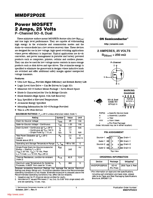
TJ, Tstg EAS
RqJA
−55 to 150 245 62.5
°C mJ
°C/W
Maximum Lead Temperature for Soldering
TL
Purposes, 0.0625″ from case for 10 sec.
Drain−1 Drain−1 Drain−2 Drain−2
ORDERING INFORMATION
Device
Package
Shipping†
MMDF2P02ER2G SO−8 2500 Tape & Reel (Pb−Free)
†For information on tape and reel specifications, including part orientation and tape sizes, please refer to our Tape and Reel Packaging Specifications Brochure, BRD8011/D.
RDS(on)
gFS
Ciss Coss Crss
td(on) tr
td(off) tf
td(on) tr
td(off) tf QT Q1 Q2 Q3
VSD trr ta tb QRR
Min
Typ
Max Unit
25
−
−
2.2
Vdc
−
−
mV/°C
mAdc
−
−
1.0
−
−
10
−
−
100 nAdc
F 系列产品说明书

F系列产品使用说明书安装操作手册注意事项:!请勿将重物至于本设备上;!请勿让任何固体或液体,掉入或渗入设备内;!请定期用刷子对电路板、接插件、机箱风机、机箱等进行除尘,在进行机体清洁工作前,请关闭电源并拔掉电源;!请勿自行对本设备进行拆卸、维修或更换零件;!避免强烈的碰撞,请勿摔落机器;!仅可在额定输入输出范围内使用。
使用环境:!请在0℃~40℃的温度下放置和使用本产品,避免阳光直射,或靠近热源;!请勿将本设备安装在潮湿的环境;!请勿将本设备暴露在多烟、多尘的环境;!请保持本产品的水平安装,安装在稳定的场所,注意防止本产品坠落;!请安装在通风良好的场所,切勿堵塞本产品的通风口。
目录第一章产品介绍 (5)1.1 产品概述 (5)1.2 产品主要功能 (5)第二章开箱检查和线缆连接 (7)2.1 开箱检查 (7)2.2 硬盘安装 (7)2.3 在机架中安装 (8)2.4 前面板 (8)2.5 后面板 (10)2.6 安装连接示意图 (10)2.7 音视频输入输出连接 (11)2.7.1 视频输入的连接 (11)2.7.2 视频输出设备的选择和连接 (11)2.7.3 音频信号的输入 (11)2.7.4 音频输出 (12)2.8 报警输入输出连接 (12)2.8.1 报警输入端口说明 (13)2.8.2 报警输出端口说明 (14)2.8.3 报警输出端继电器参数 (14)2.9 球机连接 (14)第三章基本操作 (16)3.1 开机 (16)3.2 关机 (16)3.3 登录 (16)3.4 预览 (17)3.5 桌面快捷菜单 (17)3.5.1 主菜单 (18)3.5.2 录像控制 (18)3.5.3 录像回放 (19)3.5.4 云台控制 (21)3.5.5 报警输出 (25)3.5.6 图像颜色 (26)3.5.7 输出调节 (26)3.5.8 关闭系统 (27)3.5.9 页面切换 (27)第四章主菜单 (28)4.1 主菜单导航 (28)4.2 录像功能 (29)4.2.1 录像设置 (29)4.2.2录像回放 (31)4.2.3 图片存储 (31)4.2.4 录像备份 (32)4.3 报警功能 (33)4.3.1 移动侦测 (33)4.3.2 视频遮挡 (35)4.3.3 视频丢失 (36)4.3.4 报警输入 (36)4.3.5 报警输出 (37)4.3.6 异常处理 (37)4.4 系统设置 (37)4.4.1 普通设置 (38)4.4.2 编码设置 (39)4.4.3 网络设置 (40)4.4.4 网络服务 (41)4.4.5 输出模式 (49)4.4.6 云台设置 (50)4.4.7 串口设置 (50)4.4.8 轮巡设置 (51)4.5 管理工具 (51)4.5.1 硬盘管理 (51)4.5.2 用户管理 (52)4.5.3 在线用户 (55)4.5.4 输出调节 (55)4.5.5 自动维护 (55)4.5.6 恢复默认 (56)4.5.7 系统升级 (56)4.5.8 设备信息 (57)4.6 系统信息 (57)4.6.1 硬盘信息 (57)4.6.2 码流统计 (58)4.6.3 日志信息 (59)4.6.4 版本信息 (59)4.7 关闭系统 (60)第五章常见问题解答及使用维护 (61)5.1 常见问题解答 (61)5.2 使用维护 (66)附录1.遥控器操作 (67)附录2.鼠标操作 (68)附录3.硬盘的容量计算 (69)附录4.技术参数 (70)第一章产品介绍1.1 产品概述本设备是专为安防领域设计的一款优秀的数字监控产品。
富凌(FULING)BD360中文说明书
BD360
十二、变频器的报废时注意 主回路的电解电容和印制板上电解电容焚烧时可能发生爆炸。塑胶件焚烧时会产生
有毒气体。请作为工业垃圾进行处理。 十三、关于适配电机
1、 标 准 适 配 电 机 为 鼠 笼 式 异 步 感 应 电 机 。 若 非 上 述 电 机 请 按 电 机 额 定 电 流 选 配 变 频器。若需驱动永磁同步电机的场合,请向我公司咨询;
BD360 BD360
F3.05和F3. 06功 能 码 的 说 明 。
BD360
0~200.00
5
3.00 50.0%
BD360 输 入 端 子 来 设 定 。BD 360系 列 变 频 器 标 准
BD360
0.00~200.00
0.50 Hz~F0.05 (运行频率上限)
BD360
7.5/11
20.5P-4
11/15
26/35
24/30
BD360-015G/018P-4 15/18.5
35/38.5
30/37
BD360-018G/022P-4 18.5/22 38.5/46.5
37/46
BD360-022G/030P-4
22/30
46.5/62
16
37
DZ20-100(100A) CJ20-100
45
25
25
8
55 DZ20-200(200A) CJ20-160
35
25*2(50)
75
50
35*2(70)
10
93
70
16
DZ20-400(250A) CJ20-250
50*2(95)
110
~
艾特顿PDG23P0200TFFK电路保护器说明书
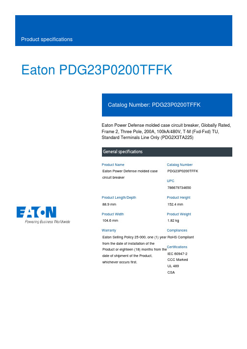
Eaton PDG23P0200TFFKEaton Power Defense molded case circuit breaker, Globally Rated, Frame 2, Three Pole, 200A, 100kA/480V, T-M (Fxd-Fxd) TU, Standard Terminals Line Only (PDG2X3TA225)Eaton Power Defense molded case circuit breakerPDG23P0200TFFK 78667973465088.9 mm 152.4 mm 104.6 mm 1.82 kg Eaton Selling Policy 25-000, one (1) year from the date of installation of theProduct or eighteen (18) months from thedate of shipment of the Product,whichever occurs first.RoHS Compliant IEC 60947-2CCC MarkedUL 489CSAProduct NameCatalog Number UPCProduct Length/Depth Product Height Product Width Product Weight WarrantyCompliancesCertifications200 AComplete breaker 2Three-polePD2 Global Class A T-M (Fxd-Fxd) TU600 Vac600 VStandard Terminals Line Only100 kAIC at 480 Vac 35/25 kAIC Icu/ 18/13 kAIC Ics @525V South Africa (IEC) 85 kAIC Icu/ 40 kAIC Ics/ 187 kAIC Icm @480V Brazil (IEC) 100 kAIC Icu/ 65 kAIC Ics/ 220 kAIC Icm @440V (IEC) 200 kAIC Icu/ 150 kAIC Ics/ 440 kAIC Icm @240V (IEC) 22 kAIC Icu @250 Vdc 200 kAIC @240V (UL) 35/25 kAIC @600V (UL/CSA)100 kAIC Icu/ 70 kAIC Ics/ 220 kAIC Icm @380-415V (IEC) 22 kAIC Icu @125 Vdc 100 kAIC @480V (UL)10 kAIC Icu/ 5 kAIC Ics/ 21 kAIC Icm @690V (IEC)Eaton Power Defense PDG23P0200TFFK 3D drawing Consulting application guide - molded case circuit breakers Amperage Rating Circuit breaker frame type Frame Number of poles Circuit breaker type Class Trip Type Voltage rating Voltage rating - max TerminalsInterrupt rating Interrupt rating range3D CAD drawing packageApplication notesBrochuresPower Defense molded case circuit breaker selection posterPower Defense brochurePower Defense technical selling bookletPower Defense molded case circuit breakers - Frame 2 product aidCatalogsMolded case circuit breakers catalogCertification reportsPDG4 CCC certificationPDG4 CB reportPower Defense Declaration concerning California’s Proposition 65PDG2 CB reportEU Declaration of Conformity - Power Defense molded case circuit breakersInstallation instructionsPower Defense Frame 1-2-3-4 IP door barrier assembly instructions -IL012278ENPower Defense Frame 2 tunnel terminal (aluminum), 150A, 3 pole instructions - IL012238EN H03Power Defense Frame 2/3/4/5/6 voltage neutral sensor module wiring instructions – IL012316ENPower Defense Frame 2 clamp terminal (steel), 20A, 3 pole instructions - IL012246EN H03Power Defense Frame 2 shunt trip UVR instructions - IL012130EN Power Defense Frame 2 locking devices and handle block instructions - IL012149ENPower Defense Frame 2 PDG2 and PDC(E)9 breaker instructions -IL012106ENPower Defense Frame 2 multi wire connector kit -PDG2X3(2)(4)TA2256W instructions - IL012242EN H01Power Defense Frame 2 box terminal (aluminum), 225A, 3 pole instructions - IL012235EN H03Power Defense Frame 2 tunnel terminal (aluminum), 100A, 3 pole instructions - IL012237EN H03Power Defense Frame 2 box terminal (steel), 100A, 3 pole instructions - IL012234EN H03Power Defense Frame 1 IEC and Frame 2 Rotary Mechanism with NFPA Handle Attachment Instructions (IL012260EN).pdfPower Defense Frame 2 tunnel terminal (aluminum), 50A, 3 pole instructions - IL012236EN H03Power Defense Frame 2 terminal kit - PDG2X3(2)(4)TA150RF instructions - IL012244EN H01Power Defense Frame 2 screw terminal_end cap kit, 225A, 3 pole instructions - IL012258EN H01Power Defense Frame 2 Direct Rotary Handle Assy With Interlock Version Instructions (IL012138EN).pdfPower Defense Frame 2 handle mech direct rotary handle instructions - IL012134ENPower Defense Frame 2 handle mech variable depth rotary handle instructions - IL012136ENPower Defense Frame 2 global terminal shield, 3 pole - IL012330EN Power Defense Frame 2 multi wire connector kit -PDG2X3(2)(4)TA2253W instructions - IL012243EN H01Power Defense Frame 2 tunnel terminal kits - PDG2X1TA225K instructions- IL012239EN H01Power Defense Frame 2 terminal kit - PDG2X3(2)(4)TA225RF instructions - IL012245EN H01Installation videosPower Defense Frame 2 TMTU Aux, Alarm, ST and UVR Animated Instructions.rhPower Defense Frame 2 withTMTU, Shunt Trip_UVR Animated Instructions.rhPower Defense Frame 2 Bell Alarm with PXR Animated Instructions.pdf.rh Power Defense Frame 2 Handle Mech Variable Depth Rotary Handle Animated Instructions.rhPower Defense Frame 2 Locking Devices and Handle Block Animated Instructions.pdf.rhMultimediaPower Defense Frame 3 Variable Depth Rotary Handle Mechanism Installation How-To VideoPower Defense Frame 2 Direct Rotary Handle Mechanism Installation How-To VideoPower Defense Frame 2 Variable Depth Rotary Handle Mechanism Installation How-To VideoPower Defense Frame 2 Aux, Alarm, Shunt Trip, and UVR How-To Video Power Defense molded case circuit breakersPower Defense BreakersPower Defense Frame 6 Trip Unit How-To VideoPower Defense Frame 5 Trip Unit How-To VideoEaton Power Defense for superior arc flash safetySpecifications and datasheetsEaton Specification Sheet - PDG23P0200TFFKTime/current curvesEaton Corporation plc Eaton House30 Pembroke Road Dublin 4, Ireland © 2023 Eaton. All Rights Reserved. Eaton is a registered trademark.All other trademarks areproperty of their respectiveowners./socialmediaPower Defense time current curve Frame 2 - PD2Selling Policy 25-000 - Distribution and Control Products and Services Molded case and low-voltage power circuit breaker health Single and double break MCCB performance revisited Intelligent circuit protection yields space savings Making a better machineMolded case and low-voltage breaker health Safer by design: arc energy reduction techniquesWarranty guidesWhite papers。
浦发空调制冷器产品说明书

496 71 5501 02 April 2011Specifications are subject to change without noticeFAN COILSALL MODELSS 1−1/2 thru 4 tonsS Available for environmentally sound R −410A systems S Factory installed piston metering device with Teflon ring S Copper tube / aluminum fin coil on standard models S Available with industry exclusive tin coated copper maintubing for additional corrosion protection S Sweat connectionsS Primary and secondary drain fittings with brass inserts S Multiple electrical entry locations S Time delay relay (TDR)S Field installed heater packages from 5 kW − 30 kW available separatelyS HUD approved for manufactured housing S 208/230−1−60 supply voltageS Units tested and certified by manufacturer to achieve a 2% or less leakage rate at 1.0 inch water column S 1 inch thick insulation with R value of 4.2S Filter (washable) available as accessoryFEM4PS ECM 5−speed motorS Multiposition installation − upflow or horizontal leftstandard, horizontal right with minor modification (field convertible to downflow with available accessory kit)S Low voltage circuit protective fuse (3amp) inline on wire harness S No Heat (Plug) Kit factory installedFSM4PS PSC 2−speed motorS Multiposition installation − upflow or horizontal leftstandard, horizontal right with minor modification (field convertible to downflow with available accessory kit)S Printed circuit board (PCB) with low voltage circuit protective fuse (5 amp)S No Heat (Plug) Kit factory installedFSU4PS PSC 2−speed motorS Upflow installation (field convertible to downflow withavailable accessory kits)S Printed circuit board (PCB) with low voltage circuit protective fuse (5 amp)WARRANTY*FEM•1 year No Hassle Replacement t limited warranty FEM, FSM, FSUS 5 year parts limited warranty− With timely registration, an additional 5 year parts limited warranty* Applies to original purchaser/homeowner, some limitations may apply. See warranty certificate for complete details.Available StylesFEM4P FSM4P FSU4P Upflow 333Horizontal 33−Downflowkit kit kitMotor ECM PSCUse of the AHRI Certified TM Mark indicates a manufacturer’s participation in the program. For verification of certification for individual products,go to .Model Number TonsNom. CFM (L/s)Dimensions H x W x D in. (mm)Filter Size in. (mm)Ship Wt lbs. (kg)FEM4P1800A FEM4P1800AT 1−1/2600 (283)42−11/16 x 14−5/16 x 22−1/16(1084 x 364 x 560)13 x 21−1/2 (330 x 546)112 (51)FSM4P1800A FSM4P1800AT FSU4P1800A FSU4P1800AT47−5/8 x17−5/8 x 22−1/16(1210 x 448 x 560)16−3/8 x 21−1/2(416 x 546)117 (53)Models continued on following pagePRODUCT SPECIFICATIONSFan Coils: FEM4P, FSM4P, FSU4P2496 71 5501 02Specifications are subject to change without noticeModel Number TonsNom. CFM (L/s)Dimensions H x W x D in. (mm)Filter Size in. (mm)Ship Wt lbs. (kg)FEM4P2400A FEM4P2400AT 2800 (378)42−11/16 x 14−5/16 x 22−1/16(1084 x 364 x 560)13 x 21−1/2(330 x 546)112 (51)FSM4P2400A FSM4P2400AT FSU4P2400A FSU4P2400AT 49−5/8 x 17−5/8 x 22−1/16(1261 x 448 x 560)16−3/8 x 21−1/2(416 x 546)128 (58)FEM4P3000A FEM4P3000AT 2−1/21000 (472)49−5/8 x 17−5/8 x 22−1/16(1261 x 448 x 560)16−3/8 x 21−1/2(416 x 546)122 (55)FSM4P3000A FSM4P3000AT FSU4P3000A FSU4P3000AT 53−7/16 x 21−1/8 x 22−1/16(1357 x 537 x 560)19−7/8 x 21−1/2(505 x 546)145 (66)FEM4P3600A FEM4P3600AT 31200 (566)49−5/8 x 17−5/8 x 22−1/16(1261 x 448 x 560)16−3/8 x 21−1/2(416 x 546)122 (55)FSM4P3600A FSM4P3600AT FSU4P3600A FSU4P3600AT 53−7/16 x 21−1/8 x 22−1/16(1357 x 537 x 560)19−7/8 x 21−1/2(505 x 546)148 (67)FEM4P4200A FEM4P4200AT 3-1/21400 (661)49−5/8 x 21−1/8 x 22−1/16(1261 x 537 x 560)19−7/8 x 21−1/2(505 x 546)157 (71)FSM4P4200A FSM4P4200AT FSU4P4200A FSU4P4200AT 156 (71)FEM4P4800A FEM4P4800AT 41600 (755)49−5/8 x 21−1/8 x 22−1/16(1261 x 537 x 560)19−7/8 x 21−1/2(505 x 546)157 (71)FSM4P4800A FSM4P4800AT FSU4P4800A FSU4P4800AT53−7/16 x 24−11//16 x 22−1/16(1357 x 627 x 560)23−5/16 x 21−1/2(592 x 546)182 (83)PRODUCT SPECIFICATIONS Fan Coils: FEM4P, FSM4P , FSU4P496 71 5501 023Specifications are subject to change without noticeFAN COIL MODEL NUMBER IDENTIFICATION GUIDEF E M 4P 1800A TF = Fan CoilS = Standard PSC E = ECM 5−Speed MOTOR TYPE U = UpflowM = MultipositionINSTALLATION TYPE4 = Environmentally Sound R −410A REFRIGERANTP = Piston Metering DeviceMETERING DEVICE1800 = 18,000 BTUH = 1−1/2 tons 2400 = 24,000 BTUH = 2 tons 3000 = 30,000 BTUH = 2−1/2 tons 3600 = 36,000 BTUH = 3 tons 4200 = 42,000 BTUH = 3−1/2 tons 4800 = 48,000 BTUH = 4 tons NOMINAL CAPACITYA = StandardAT = Tin coated copper tubesSALES CODE / FEATURESACCESSORIES PART NUMBER IDENTIFICATION GUIDEEB AC 01NCBAEB = Evaporator Blower AC = Accessory01 = Product Identifier Number NCB = Non −Combustible Base Kit DFK = Down Flow KitPLG = Power Plug (no heat kit)SPK = Single Point Wiring Kit FKS = Filter Kit Small FKM = Filter Kit Medium FKL = Filter Kit LargeFKX = Filter Kit Extra LargeCTK = Condensate Trap Kit (PVC pipe)Sales CodeELECTRIC HEATER MODEL NUMBER IDENTIFICATION GUIDEEHK 05A K N1EHK = Electric Heater Kit05 = 5 kW 07 = 7 kW 09 = 9 kW 10 = 10 kW 15 = 15 kW 18 = 18 kW 20 = 20 kW 25 = 25 kW 30 = 30 kW NOMINAL HEAT VALUE Sales CodeK = 208 / 230 single −phase H = 208 / 230, 3−phaseKC = 208 / 230, supplied as single phase, field convertible to 3−phase HC = 208 / 230 supplied as 3−phase, field convertible to single phase VOLTAGE (60 Hz)Product Identifier Engineering CodePRODUCT SPECIFICATIONS Fan Coils: FEM4P, FSM4P, FSU4P4496 71 5501 02Specifications are subject to change without noticeREQUIRED CLEARANCES − ALL MODELS inches (mm)No Heaters All Sides0From Supply Duct 0With HeatersAll Sides0From First 3 feet of Supply Duct to Combustibles 1 (25)From Supply Duct to Combustibles after 3 feetFEM4P inches (English)Unit Size A B C D E FG H 180042−11/1614−5/1612−7/1612−5/822−1/16112119−13/16240042−11/1614−5/1612−7/1612−5/822−1/16112119−13/16300049−5/817−5/815−3/415−5/822−1/16112119−13/16360049−5/817−5/815−3/415−5/822−1/16112119−13/16420049−5/821−1/819−1/419−1/822−1/16112119−13/16480049−5/821−1/819−1/419−1/822−1/16112119−13/16FEM4P (mm SI Metric)Unit Size A B C D E FG H 180010843643163135602795335032400108436431631356027953350330001261448400397560279533503360012614484003975602795335034200126153748948656027953350348001261537489486560279533503PRODUCT SPECIFICATIONS Fan Coils: FEM4P, FSM4P , FSU4P496 71 5501 025Specifications are subject to change without noticeREQUIRED CLEARANCES − ALL MODELS inches (mm)No Heaters All Sides0From Supply Duct 0With HeatersAll Sides0From First 3 feet of Supply Duct to Combustibles 1 (25)From Supply Duct to Combustibles after 3 feetFSM4P , FSU4P inches (English)Unit Size A B C D E F GH 180047−5/817−5/815−3/415−5/822−1/16112119−13/16240049−5/817−5/815−3/415−5/822−1/16112119−13/16300053−7/1621−1/819−1/419−1/822−1/16112119−13/16360053−7/1621−1/819−1/419−1/822−1/16112119−13/16420049−5/821−1/819−1/419−1/822−1/16112119−13/16480053−7/1624−11/1622−3/422−11/1622−1/16112419−13/16FSM4P , FSU4P mm (SI Metric)Unit Size A B C D E F GH 180012104484003975602795335032400126144840039756027953350330001357537489486560279533503360013575374894865602795335034200126153748948656027953350348001357627578576560279610503PRODUCT SPECIFICATIONSFan Coils: FEM4P, FSM4P, FSU4P10496 71 5501 02Specifications are subject to change without noticeDIMENSIONAL DATA (refer to drawings)ModelSize (tons)Dimensions inches (English)Coil Type Ship.WT lbs.A B C D E F G HJ Suct.LiquidFEM4P1800A(T)1−1/242−11/1614−5/1612−7/1612−5/1610−7/1618−1/818−5/8—125/83/8Slope112FSM4P1800A(T)47−5/817−5/815−3/415−5/815−3/823−1/823−5/8—3/4117FSU4P1800A(T)FEM4P2400A(T)242−11/1614−5/1612−7/1612−5/1610−7/1618−1/818−5/8—125/83/8Slope112FSM4P2400A(T)49−5/817−5/815−3/415−5/815−3/823−1/823−5/8—3/4128FSU4P2400A(T)FEM4P3000A(T)2−1/249−5/817−5/815−3/415−5/815−3/823−1/823−5/8—173/43/8Slope122FSM4P3000A(T)53−7/1621−1/819−1/419−1/819−3/1626−15/1627−1/2—145FSU4P3000A(T)FEM4P3600A(T)349−5/817−5/815−3/415−5/815−3/823−1/823−5/8—173/43/8Slope122FSM4P3600A(T)53−7/1621−1/819−1/419−1/819−3/1626−15/1627−1/2—148FSU4P3600A(T)FEM4P4200A(T)3−1/249−5/821−1/819−1/419−1/815−11/1623−7/1623−1/8——7/83/8“A”157FSM4P4200A(T)49−5/821−1/819−1/419−1/815−11/1623−7/1623−1/8156FSU4P4200A(T)FEM4P4800A(T)449−5/821−1/819−1/419−1/815−11/1623−7/1623−1/8——7/83/8“A”157FSM4P4800A(T)53−7/1624−11/1622−3/422−11/1619−1/227−1/426−15/16182FSU4P4800A(T)ModelSize (tons)Dimensions mm (SI Metric)Coil Type Ship.WT kg A B C D E F G HJ Suct.LiquidFEM4P1800A(T)1−1/21084364316313265460473—3051610Slope51FSM4P1800A(T)1210448400397391587600—1953FSU4P1800A(T)FEM4P2400A(T)21084364316313265460473—3051610Slope51FSM4P2400A(T)1261448400397391587600—1958FSU4P2400A(T)FEM4P3000A(T)2−1/21261448400397391587600—3051910Slope55FSM4P3000A(T)1357537489486487684699—66FSU4P3000A(T)FEM4P3600A(T)31261448400397391587600—3051910Slope55FSM4P3600A(T)1357537489486487684699—67FSU4P3600A(T)FEM4P4200A(T)3−1/21261537489486399595587——2210“A”71FSM4P4200A(T)126153748948639959558771FSU4P4200A(T)FEM4P4800A(T)41261537489486399595587——2210“A”71FSM4P4800A(T)135762757857649569268483FSU4P4800A(T)PRODUCT SPECIFICATIONS Fan Coils: FEM4P , FSM4P , FSU4P496 71 5501 0211Specifications are subject to change without noticePHYSICAL DATAModelSize180024003000360042004800Metering Device** − Factory Installed Piston Size (R −410A)FEM4P 525767707680FSM4P, FSU4P 525767707680Blower DataCFM(nominal)FEM4P 6008001000120014001600FSM4P, FSU4P 6008001000120014001600MotorType FEM4P ECM 5−speed FSM4P, FSU4P PSC (Permanent Split Capacitor) 2−speedHPFEM4P 1/31/21/31/21/23/4FSM4P, FSU4P 1/61/41/31/31/21/2Filter Data (washable, available as accessory)FEM4P 13 x 21−1/216−3/8 x 21−1/219−7/8 x 21−1/2FSM4P, FSU4P 16−3/8 x 21−1/219−7/8 x 21−1/223-5/16 x 21-1/2Coil Data − Face Area ft 2 (m 2)FEM4P2.23 (0.21) 2.23 (0.21) 2.97 (0.28) 2.97 (0.28) 4.45 (0.41) 4.45 (0.41)FSM4P, FSU4P2.97 (0.28) 2.97 (0.28)3.46 (0.32) 3.46 (0.32)4.45 (0.41)5.93 (0.55)Refrigerant Line Connections (sweat)FEM4PLiquid inch (mm)3/8 (10)Suction inch (mm)5/8 (16)5/8 (16)3/4 (19)3/4 (19)7/8 (22)7/8 (22)FSM4P,FSU4P Liquid inch (mm)3/8 (10)Suction inch (mm)3/4 (19)3/4 (19)3/4 (19)3/4 (19)7/8 (22)7/8 (22)ELECTRICAL DATA, FAN COIL ONLY WITHOUT ELECTRIC HEATModel208/230V, single phase, 60 Hz Motor Full Load Amps (FLA )Minimum Circuit Ampacity (MCA )Maximum Fuse/Ckt Bkr Amps (Max OverCurrent Protection − MOCP )FEM4P18002.83.515FSM4P1800, FSU4P18000.9 1.215FEM4P24004.15.115FSM4P2400, FSU4P24001.4 1.815FEM4P30002.83.515FSM4P3000, FSU4P30001.4 1.815FEM4P36004.15.115FSM4P3600,FSU4P36001.72.215FEM4P42004.15.115FSM4P4200, FSU4P42002.83.515FEM4P48006.07.515FSM4P4800, FSU4P48002.73.415**Always check piston size on indoor unit to see if it matches required piston on outdoor unit nameplate. If it does not match, replace indoor piston with piston size marked on outdoor unit nameplate .PRODUCT SPECIFICATIONS Fan Coils: FEM4P, FSM4P, FSU4P12496 71 5501 02Specifications are subject to change without noticeNOTES:1.Airflow based upon dry coil at 230v with factory −approved filter and electric heater (2 element heater sizes 1800 through 3600, 3element heater sizes 4200 through 4800). For FEM4P models, airflow at 208 volts is approximately the same as 230 volts because the ECM motor is a constant torque motor. The torque doesn’t drop off at the speeds the motor operates.2.T o avoid potential for condensate blowing out of drain pan prior to making drain trap:Return static pressure must be less than 0.40 in. wc.Horizontal applications of 4200 − 4800 sizes must have supply static greater than 0.20 in. wc.3.Airflow above 400 cfm/ton on 4800−4800 size could result in condensate blowing off coil or splashing out of drain pan.PRODUCT SPECIFICATIONS Fan Coils: FEM4P , FSM4P , FSU4P496 71 5501 0213Specifications are subject to change without noticePRODUCT SPECIFICATIONS Fan Coils: FEM4P, FSM4P, FSU4P14496 71 5501 02Specifications are subject to change without noticeSTATIC PRESSURE CORRECTION FOR ELECTRIC HEATERS (inches of water column)Airflow performance chart was developed using fan coils with 10 kW electric heater (2 elements) in the 1800 − 3600model sizes, and 15 kW electric heaters (3 elements) in the 4200 − 4800 model sizes.When using a different number of heater elements, adjust the static pressure numbers by adding or subtracting the values in this table (for a given CFM, more electric heater elements create higher static pressure drop).Model SizeHeater kWNo Heater 3 or 58 or 109 or 152018, 24, or 30Number of Heat Elements0123461800+0.02+0.010−0.02−0.04−2400+0.02+0.010−0.02−0.04−3000+0.02+0.010−0.02−0.04−3600+0.02+0.010−0.02−0.04−4200+0.04−+0.020−0.02−0.104800+0.04−+0.020−0.02−0.10PRODUCT SPECIFICATIONS Fan Coils: FEM4P, FSM4P, FSU4P16496 71 5501 02Specifications are subject to change without noticeACCESSORIESDescriptionPart NumberUse with modelsFSM4P & FSU4P models FEM4P modelsDisconnect KitEBAC01DSC use with All Heaters 3 kW thru 10 kWDownflow Base KitEBAC01NCB −1800, 2400EBAC02NCB 1800, 24003000, 3600EBAC03NCB3000, 3600, 4200, 48004200, 4800Downflow Conversion Kit − Slope Coil EBAC01DFS 1800, 2400, 3000, 36001800, 2400, 3000, 3600Downflow Conversion Kit − “A” Coil EBAC02DFA 4200, 48004200, 4800Single Point Wiring Kit EBAC01SPKonly for use with 15 kW & 20 kW fused heatersSingle Point Wiring Kit − Square D rJumper Bar AssemblyAMFK20SPA orSquare D r part #QOU14100JBAFOnly for use withEHK15AKB and EHK20AKB breaker heaters Filter Kit (washable, box of 12)EBAC01FKS −1800, 2400EBAC01FKM 1800, 24003000, 3600EBAC01FKL 3000, 3600, 42004200, 4800EBAC01FKX 4800−No Heat (Plug) Kit (box of 6)EBAC01PLG FSU4P −ALLFSM4P and FEM4P − Factory InstalledPVC Condensate Trap Kit (box of 50)EBAC01CTK ALL ALL Downflow Gasket KitEBAC01GSK ALL ALL(required for horizontal right and downflow)TXV Kit, R −410ANAEA40501TX1800, 2400, 30001800, 2400, 3000NAEA40601TX 3600, 42003600, 4200NAEA40701TX48004800TXV Kit, R −22NAEA20101TX 1800, 2400, 3000, 3600, 42001800, 2400, 3000, 3600, 4200NAEA20201TX48004800ELECTRIC HEATERSPart Number DescriptionUse with Model SizesEHK05AKN 5 kW, single phase, no internal circuit protection ALL EHK05AKB 5 kW, single phase, with circuit breakers ALL EHK07AKN 8 kW, single phase, no internal circuit protection ALL EHK07AKB 8 kW, single phase, with circuit breakersALLEHK09AKCN 9 kW, supplied as single phase, field convertible to 3−phase, no inter-nal circuit protection3600, 4200, 4800EHK10AKN 10 kW, single phase, no internal circuit protection ALL EHK10AKB 10 kW, single phase, with circuit breakers ALLEHK15AKF 15 kW, single phase, with fuses2400, 3000, 3600, 4200, 4800EHK15AKB 15 kW, single phase, with circuit breakers 2400, 3000, 3600, 4200, 4800EHK15AHN 15 kW, 3−phase, no internal circuit protection 3600, 4200, 4800EHK18AHN 18 kW, 3−phase, no internal circuit protection 4200, 4800EHK20AKF 20 kW, single phase, with fuses3000, 3600, 4200, 4800EHK20AKB 20 kW, single phase, with circuit breakers3000, 3600, 4200, 4800EHK25AHCF 24 kW, supplied as 3−phase, field convertible to single phase, with fuses 4800EHK30AHCF30 kW, supplied as 3−phase, field convertible to single phase, with fuses4800International Comfort Products, LLC Lewisburg, Tennessee 37091 USA 。
KPFK系列复合开关使用说明书

KPFK系列低压电容投切复合开关使用说明书南京卡鹏科技有限公司二零零九年引用标准GB/T14598.14-1998(idt IEC255-22-2)电磁兼容静电放电试验标准GB/T14598.9-1995(idt IEC255-22-3)辐射电磁场干扰标准GB/T14598.13-1998(idt IEC255-22-1)脉冲群干扰符标GB/T14598.10-1996(idt IEC255-22-4)快速瞬变干扰标准IEC1000-4-5《电磁兼容性(EMC)》标准DL/T478-3001 4.13.1机械性能振动标准DL/T478-3001 4.13.2 冲击试验标准DL/T478-3001 4.13.3 碰撞试验标准1.概述KPFK系列智能低压复合开关是一种智能化环保型低压电容投切开关,采用单片机控制投切,智能监控可控硅、继电器以及输入电源和负载的运行状况,具有完善的保护功能。
其工作原理为:将可控硅与磁保持继电器并联接通电路。
可控硅在投入和切除的瞬间进行过零投切,即电压过零时刻投入,电流过零时刻切除,可控硅短时间导通后,转为磁保持继电器接通运行。
因此,它既具有可控硅开关过零投切无涌流的优点,又具有机械触点运行无功耗的长处,也就避免了可控硅运行发热和机械触点投切火花的缺陷,是一种较为理想的投切开关。
由于磁保持继电器在吸合与断开的瞬间都没有涌流和火花,因此,它的电器寿命远高于设计的寿命,而它的机械寿命高达百万次,可以保证长期运行。
2.使用条件1)环境温度:-25℃至+70℃2)海拨高度:不超过2000M3)大气条件:空气湿度不超过90%4)环境条件:介质无导电尘埃3.选型及配置1)型号解释KPFK□□ S - 1616:可控硅耐压1600VS:共补型、D:分相型030、045或060:额定电流KPFK:KP表示,卡鹏,FK表示复合开关如:三相型KPFK045S-16分相型KPFK045D-164.技术参数基本参数●额定电压:AC 380V±20%50Hz ± 10%●额定电流:30A、45A、60A三种规格●工作电源:AC 220V±20%50Hz ± 10%●电源电压谐波畸变率≤5.0 %●控制电压:直流电压5~12V / 10mA 由控制器提供控制电压●本机功耗:≤3V A●动作响应时间:≤1S 即控制器发出投入或切除信号后,复合开关在1秒内完成投入或切除动作●重复投切时间:≤2S 即复合开关切除后,只需过2秒就可以重新投电容器,而不必等待3分钟的电容放电时间。
欧科变频器说明书文档
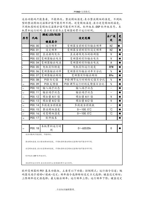
频率;加速时间1;减速时间1;运行方向选择;载波频率设定;功能参数恢复;AVR功能选择
欧科变频器的P01基本功能组,主要有以下功能:控制模式;运行指令信道;编码器及端子递增+/递减-设定;频率指令选择;转矩设定方式选择;键盘设定转矩;上限频率设定源选择;最大输出频率;运行频率上限;运行频率下限;键盘设定频率;加速时间1;减速时间1;运行方向选择;载波频率设定;功能参数恢复;AVR功能选择
P01组基本功能组
P02.00启动运行方式;P02.01 启动开始频率;P02.02启动频率保持时间;P02.03 启动前制动电流;P02.04 启动前制动时间;P02.05 停机方式选择;P02.06 停机制动开始频率;P02.07 停机制动等待时间;P02.08 停机直流制动电流;P02.09 停机直流制动时间;P02.10 正反转死区时间;P02.11 上电端子运行保护选择;P02.12 预留
欧科变频器P02启停控制组主要具有以下功能:P02.00启动运行方式;P02.01 启动开始频率;P02.02启动频率保持时间;P02.03 启动前制动电流;P02.04 启动前制动时间;P02.05 停机方式选择;P02.06 停机制动开始频率;P02.07 停机制动等待时间;P02.08 停机直流制动电流;P02.09 停机直流制动时间;P02.10 正反转死区时间;P02.11 上电端子运行保护选择;P02.12 预留
P02组启停控制组。
德力西9600变频器说明书第二版
目录目录前言第一章安全运行及注意事项 (1)第二章产品信息 (3)2.1 铭牌数据及命名规则 (3)2.2 技术规范 (4)2.3 CDI9600系列小功率矢量变频器 (6)2.4 外型及安装尺寸 (7)2.5 日常使用的保养与维护 (8)第三章变频器的安装及接线 (12)3.1 变频器前盖与数字操作键盘的安装 (12)3.1.1 变频器前盖的安装 (12)3.1.2 数字操作键盘的安装 (12)3.2 安装地点及空间的选择 (13)3.3 安装地点及空间的选择 (15)3.3.1 主回路输入侧的接线注意事项 (15)3.3.2 主回路输出侧的接线注意事项 (16)3.3.3 主回路输出侧的接线注意事项 (18)3.4 控制电路的接线 (20)3.4.1控制电路端子排列及接线图 (20)3.4.2 控制电路端子的功能 (22)3.5 接地 (24)Ⅰ目录第四章键盘操作与运行 (25)4.1 操作方式的选择 (25)4.2 试运行及检查 (25)4.2.1 试运行前的注意事项及检查 (25)4.2.2 试运行 (26)4.2.3 运行时的检查 (26)4.3 键盘的操作方法 (27)4.3.1 键盘按键及功能 (27)4.3.2 键盘显示方式 (27)4.3.3 查看/设定参数的方法(用数字键盘) (29)4.3.4 键盘设定频率的方法 (30)第五章功能参数表 (31)第六章功能参数说明 (47)6.1 基本功能参数P00组 (47)6.2 辅助功能参数P01组 (64)6.3 输入输出端子与多段速运行功能P02组 (78)6.4多段速运行功能P03组 (97)6.5 其他功能参数P04组 (106)6.6 显示功能参数P05组 (110)第七章故障排除 (111)7.1 故障的诊断与排除措施 (111)7.2 报警显示和解释 (113)7.3 电机故障和排除措施 (113)附录RS-485通讯协议修正 (115)Ⅱ第一章 安全运行及注意事项第 1 页第一章 安全运行及注意事项CDI9600系列小功率矢量变频器安装、运行、维护和检查之前要认真阅读本说明书。
软启动器中文样本_082008

電動機電壓
電壓 V
100 %
直接起動
星 / 三角起動
軟起動
58 %
70 % 30 %
可調節的起 動斜坡曲線
電動機電流
電流 I
直接起動
時間
星 / 三角起動
軟起動
電動機力矩
力矩 T
直接起動
電動機轉速
星 / 三角起動 軟起動
電動機轉速
圖中所示的是直接起動、星/三角起動和軟起動在電動機電壓 (V)、電動機 電流 (I) 和電動機力矩 (T) 時的不同表現。
10 A
16 A
25 A
32 A
32 A
隔離開關熔斷器組 (適配的gG隔離開關熔斷器組)
型號 OS32D
主接觸器 (用於斷開主電路)
型號 A9
A9
A9
A12
A16
熱過載繼電器 (用於保護電動機)
型號 TA25DU
旁路觸點
內置
PSR25 ... PSR30
PSR25 11 25 15 24.2
PSR30 15 30 20 28
MS325
MS450
50 A
63 A
A26
A30
型號說明
PSR 30-600-70
控制回路工作電壓 70:100-240V AC 81:24V DC 主回路工作電壓 額定工作電流 緊湊型
1/1
應用說明
PSR - 緊湊型系列,覆蓋電動機電流范圍從3A至105A,是ABB軟起動器家族的 最新成員,設計獨特、外形緊湊。
軟起動器的工業信息化
得益於ABB廣泛推行產品標準化的概念,如今通過工業信 息化的元件-無論它們是產品還是系統,軟件還是硬 件,都可以作為更大型解決方案的 "構建模塊" ,實現在實 時自動化和信息系統中的無縫運作。在產品的層次上,帶 有ABB工業信息化標誌的產品可以完美地配合工作。關於 所有產品的相關信息都有基於Aspect Object技術的電子版 本。ABB工業信息化的承諾就是確保每一個產品在其壽命 周期中都配備有進行有效安裝、使用和維護所需的工具。 顧客同樣可以瀏覽/lowvoltage的網址直接 查找所有產品相關的資料小冊子、目錄、証書和圖紙。
智能应急疏散系统

技术参数
系统设计1
• • • • 9米左右一个标志灯具,箭头指向安全出口; 6-7米一个照明灯具; 安全出口标志。 灯具输入功率:标志灯具为输入功率1W 照明灯具输入功率为4W、6W • 分配电配置:满载输出功率0.5KVA。电源可以分配8 路输出,每路输出小于140W,每路所带灯具数量小 于25台;通讯可以分配出4路,每路所带灯具数量小 于60台。 • 集中电源的输出功率5KVA 。
系统框图
系统组成
应急照明控制器
消防应急灯具专用应急电源 应急照明分配电装置 集中电源集中控制型消防应急标志灯具 疏散预案软件
灯具
分为照明灯具和标志灯具。 二总线,两根电源线,无极性。 电子编码,占用一个地址点。 具有频闪、状态监测、调向、灭灯、楼层 指示等功能。 采用DC36V安全电压供电,避免了人身触 电,安全可靠。 采用LED光源,绿色环保、寿命长。 具有红外遥控功能,方便灯具的调试、测 试及维护。 内嵌CPU控制模块,能接收控制器和分配 电装置的控制指令。 实时监测灯具的光源、连接线等的状态信 息,并上传给控制器。
技术参数
分配电装置系统图
LD-D-5KVA-502消防应急灯具专用应急电源
能接收应急照明控制器的指令,并上传本 机状态信息。 当主电失电或火灾时为应急照明分配电装 置和灯具提供备用电源。 可实现智能分布、点对点投入备用电源。
具有主电电压、充电、故障和应急状态指 示功能,并具有显示功能。 具有电池巡检、每节电池电压显示功能。 具有故障声光报警功能,并指示故障类型。 具有过压、欠压、过载、过放电保护功能。
标志灯具技术参数
标志灯具外形与安装
照明灯具技术参数
照明灯具外形与安装
LD-FP-601分配电装置
- 1、下载文档前请自行甄别文档内容的完整性,平台不提供额外的编辑、内容补充、找答案等附加服务。
- 2、"仅部分预览"的文档,不可在线预览部分如存在完整性等问题,可反馈申请退款(可完整预览的文档不适用该条件!)。
- 3、如文档侵犯您的权益,请联系客服反馈,我们会尽快为您处理(人工客服工作时间:9:00-18:30)。
FEATURESLow pressure (0~1)Easy to use dual in-line package (DIP)Wide 0~60compensated temperature range Span calibration to 2% for low pressure Zero offset calibrationHigh performance, stable packaged silicon chip Gage and differential pressure configurationsAPPLICATIONSMedical Equipment Respiration HVACLevel Detection Flow Measurement Industrial ControlMODEL NUMBER FOR ORDERINGMAXIMUM RATINGOperating Input Current 1.5constant, Ambient Temperature Ta=25mV 2mV 2.50.650.32.02.0PIN CONFIGURATIONRELIABILITY TESTCover 9.40 13.973.3 OD 2.03ID PACKAGE CONFIGURATION AND DIMENSIONS (U nit : mm )120, 1000hrs-40, 1000hrs255, 1 million times, Rated Pressure -20, 1 million times, Rated Pressure100, 1 million times, Rated Pressure 40, 90%RH, 1 million times, Rated Voltage 260, 10 seconds -40~120, 30minutes/1Cycle, 100Cycles Amplitude : 1.5mm, Frequency : 10~55Hz,X, Y, Z(3-directions), 2 hrs each direction 75cm height, 2 timesBending Strength : 4.9N(0.5kgf), Right/Left 90, 1time 230, 5 secondsNote1. Mounting on printed circuit boardsWhen mounting a transistor on a printed circuit, it is assumed that lead wires will be processed or reformed due to space limitation or relations with other components. Even if no such special processing reforming is conducted exercise care on the following points :(a) Make the spaces of lead wire inserting holes on the printed circuit board the same as those of lead wires on a transistor.(b) Even if The spaces are not the same, do not pull the lead wires or push heavily against the sensor element.(c) Use a spacer for form a lead maintain space between a sensor and a printed circuit board, rather than closely contacting them with each other.(d) When forming a lead prior to mounting onto a board- Bend the lead at a point 3mm or more apart from the body(Lead root).- Bend one lead wire after securing the other lead wire. (near the main body)- Keep space between the sensor main body and and a fixing jig.- When bending the lead along the jig, be careful not to damage it with an edge of the jig.- Follow other precautions described in respective standard (e) When mounting a sensor onto a heat sink - Use the specified accessory.- Drill threaded holes on the heat kink as per specifications and keep the surface free from burrs and undulations.- Use KEC’s recommended silicon grease.- Tighten the screw within the specified torque.- Never apply a pneumatic screwdriver to a transistor main body.(f) Do not bend or stretch the lead wires repeatedly.When pulling in the axial directions, apply 500g or 600gpower, depending on the shapes of lead wires.2. SolderingWhen soldering a sensor to a printed circuit board, the soldering temperature is usually so high that it adversely affects the sensor.Normally, tests are conducted at a soldering temperature of 265for 10 seconds or 300for 3 seconds. Be sure to complete soldering procedures under these conditions of temperature and time.Be careful to select a type of flux that will neither corrode the lead wires nor affect the electrical characteristics of a sensor.The basic precautions for soldering procedures are as follows :(a) Complete soldering procedures in a time as short as possible.(b) Do not apply stress to a sensor after soldering by correcting or modifying its location or direction.(c) For a sensor employing a heat sink, mount it on the heat sink first: then solder this unit to a printed circuit board after confirming that it is fully secured.(d) Do not directly solder the heat-radiating portion of a sensor to a printed circuit board.(e) In flow solder jobs, sensors are apt to float on the solder due to solder surface tension. When adjusting the locations of sensor, be careful not to apply excessive stress to the roots ofthe sensor lead wires.(f) When using a soldering iron select those which have less leakage, and be sure to ground the soldering iron.3. Cleaning a circuit boardAfter soldering, circuit boards must be cleaned to remove flux.Observe the following precautions while cleaning them(a) When cleaning circuit boards to remove flux, make sure that no residual reactive ions such as Na or Cl ions remain. Note that organic solvents react with water to generate hydrogen chloride and other corrosive gases which can degrade device performance.(b) Do not rub the indication marks with a brush or one ’s fingers when cleaning or while a cleaning agent is applied to the markings.(c) There are ultrasonic wave cleaning methods which offer a high cleaning effect within a short time. Since there methods involve a complicated combination of factors such as the cleaning bath size, ultrasonic wave vibrator output, andprinted circuit board mounting method, there is fear that theservice life of airtight seal-type sensors may be extremely shortened. Therefore, as far as possible avoid using the ultrasonic wave cleaning method.- Basic requirements of ultrasonic wave cleaning method.Frequency : 27~29kHzOutput : 300W or less (300W/or less)Recommended solvents : Refer to details above Cleaning time : 30seconds or less。
