RSM-SY6使用手册
Synchro_6_使用手册

Synchro 6 使用手册Synchro软件是一套完整的城市路网信号配时分析与优化的仿真软件;与“道路通行能力手册(HCM2000)”完全兼容,可与“道路通行能力分析软件(HCS)”及“车流仿真软件(SimTraffic)”相互衔接来整合使用,并且具备与传统交通仿真软件CORSIM, TRANSYT-7F等的接口,它生成的优化信号配时方案可以直接输入到Vissim软件中进行微观仿真。
Synchro软件既具有直观的图形显示,又具有较强的计算能力,能很好地满足信号配时评价的各项要求,其仿真结果对交通管理者具有极高的参考价值,是一套易学易用、能与交通管理与控制的专业知识密切结合的有效分析工具。
目前,Trafficware公司已推出Synchro 7版本,与Synchro 6相比,Synchro 7增加了不少新的功能。
教学要求:本课程将在《交通管理与控制》课程的基础上,通过学习Synchro软件的主要功能与其操作步骤,能以实例探讨来阐述此软件的使用方法与运算结果及其输出,并具备自行针对市区各类型路网的各种道路交通现状进行分析,掌握包括信号配时优化设计在内的各种交通工程改善方案及其仿真分析与评估的专业技能。
一、引言Synchro软件以城市道路信号系统作为分析对象,具备通行能力分析仿真,协调控制仿真,自适应信号控制仿真等功能,包括:1.单一交叉口/干道/区域交通系统的通行能力分析2.单一交叉口/干道/区域交通系统的现状服务水平分析3.单一交叉口/干道/区域交通系统的现状信号运作绩效评估4.单一交叉口的信号配时设计5.干道/区域交通系统的信号协调控制系统设计Synchro软件同时结合了道路通行能力分析、服务水平评估及信号配时设计等多项功能,且可同时适用于市区独立交叉口(十字形或T形、Y形)、干道系统与区域交通系统等多种道路几何类型。
此外,Synchro 在从事信号配时设计时,其配时优化目标的设定,除可沿用传统独立交叉口配时设计中所常用的最小化平均延误外,还加入了干道续进绿波带宽最大化的信号协调控制目标,同时还兼顾到交叉口相位设计的需要。
MRAS6中文操作手册
V 1.0目录操作须知 (3)仪器介绍 (4)安全通则 (5)密闭微波消解中不适消解的物质 (6)高温下化学物质的安全要点 (6)安装 (7)工具 (7)安装地点 (7)开箱 (8)检查 (8)仪器描述 (9)软件图标和按键指引 (13)创建传统方法 (14)编辑方法 (19)删除方法 (20)运行方法 (21)系统菜单 (25)工具 (25)系统 (25)诊断 (26)功率 (26)红外 (26)压力 (27)升级管理 (27)设置 (28)维护、故障解决及服务 (37)清洁 (37)微波泄漏测试 (37)微波功率测试 (37)温度标定(红外传感器) (40)红外温度传感器的校验 (42)压力标定 (43)升级固件 (43)故障解决指南 (44)规格 (47)保修 (48)操作须知MARS6仪器所使用电源必须具有良好接地,以防电源短路对仪器造成严重伤害。
仪器配备了接地插头,必须插入正常接地的插座中。
如果接地要求不能达到或者怀疑仪器没有正常接地,请咨询电工或者相关认证部门。
如果需要使用延长线,仅适用3插头延长线,并保证插入3插头接地插座。
延长线的标号必须等于或者高于仪器原装线指标。
仪器不应该放置在易受电磁干扰的设备旁边。
仪器应远离磁场,微波泄漏量应小于5 mW/cm 2。
本仪器如果选配有磁力搅拌功能会产生一定的磁场,患有心脏病或体内有心脏起搏器的人员请勿操作使用仪器。
仪器发生问题时,维修应由CEM 公司专业工作人员来完成。
本仪器所通过美国、加拿大、欧共体相关安全标准。
本手册中使用的Teflon 为E.I. DuPont 公司注册商标。
仪器介绍微波加速反应系统(MARS6)是一种应用于消解、萃取、蛋白水解浓缩、干燥、合成等实验室工作的仪器。
它的主要功能是为AA(原子吸收)、ICP(电感耦合等离子发射光谱)和LC(液相色谱)等分析的前处理加速样品反应,缩短处理时间,从而提高工作效率。
MARS 组成:◆磁控管(输出功率:0~1800W±15%,IEC)◆防腐内腔◆排风扇及排气管◆数字化电脑编程,每个程序最高可达5步◆自动转盘◆三个内锁开关和一个检测开关保护仪器在开门时停止微波发射MARS 使用微波能量加热样品。
SY6000用户手册V3.0完整版(13.12月修订)

SY6000系列变频器 用户手册版本 V3.0修订日期 2014年2月前 言感谢您购买神源SY6000系列变频器!本用户手册介绍了如何正确使用SY6000系列变频器。
在使用SY6000系列变频器之前,请认真阅读本手册,以确保正确使用以及使用者和设备的安全。
同时,请您妥善保管本手册,以备今后调试、维护和检修时使用。
目 录前 言..........................................................................................................1 目 录..........................................................................................................1 第1章 综述..............................................................................................5 1.1购入检查..............................................................................................5 1.2 安全注意事项......................................................................................5 1.3 变频器的综合技术特性......................................................................7 1.4 变频器型号说明. (8)1.5 变频器铭牌说明..................................................................................9 1.6 变频器系列规范................................................................................10 第二章 安装............................................................................................11 2.1 变频器外形尺寸................................................................................12 2.2 安装场所要求和管理........................................................................16 2.2.1 温湿度........................................................................................16 2.2.2 海拔高度....................................................................................16 2.2.3 其它环境要求............................................................................16 2.2.4 防范措施....................................................................................16 2.3 变频器安装方向和空间....................................................................17 第3章 接线............................................................................................18 3.1 与外围设备的连接图........................................................................20 3.2 接线图...............................................................................................21 3.3 端子排组成与接线............................................................................22 3.3.1 主回路端子排功能.....................................................................22 3.3.2 主回路的连接............................................................................22 3.3.3 控制回路端子............................................................................27 3.3.4 控制回路的连接........................................................................28 3.3.5 跳线端子说明............................................................................29 3.4 外围电气元件造型参考表. (30)3.4.1 断路器、接触器、线径规格 (30)3.4.2 输入/输出交流电抗器和直流电抗器规格 (31)3.5符合EMC要求的安装指导 (32)3.5.1传导干扰处理 (32)3.5.2射频干扰处理 (32)第4章键盘操作指南 (40)4.1键盘说明 (40)4.1.1 键盘示意图 (40)4.1.2 按键功能说明 (42)4.1.3 指示灯说明 (43)4.2键盘基本操作 (43)4.2.1 直接显示状态 (43)4.2.2 显示参数的切换 (43)4.3快速菜单 (45)4.3.1 快捷菜单操作 (45)4.3.2 快捷调试模式 (46)第5章功能代码参数说明 (48)F0组基本功能组 (48)F1组频率设定功能组 (50)F2组起停控制组 (53)F3组辅助运行功能组 (57)F4组输入端子组 (61)F5组输出参数组 (67)F6组增强功能组 (70)F7组保护参数组 (76)F8组PID控制组 (80)F9组简易PLC及多段速控制组 (84)FA组键盘与显示组 (89)F B组电机参数组 (93)FC组串行通讯组 (93)F D组机型选择组 (95)FE组厂家参数组 (96)第6章制动单元和制动电阻 (97)6.1制动单元型号 (97)6.2制动电阻的选用 (97)6.2.1 阻值的选择 (97)6.2.2 功率的选择 (97)6.3制动单元外形尺寸 (100)6.4制动单元的连接 (100)第7章故障及对策 (101)7.1故障代码及原因分析 (101)7.2常见故障及其处理方法 (103)第8章保养和维护 (105)8.1日常维护 (105)8.2定期维护 (105)8.3变频器易损件更换 (106)8.4变频器的保修 (106)第9章通讯协议 (107)9.1协议内容 (107)9.2应用方式 (107)9.3总线结构 (107)9.4协议说明 (108)9.5通讯帧结构 (108)9.6命令码及通讯数据描述 (111)9.6.1 命令码:03H(0000 0011) (111)9.6.2 命令码:06H(0000 0110) (112)9.6.3 命令码:08H(0000 1000) (114)9.6.4 通讯帧错误校验方式 (116)9.6.5 通信数据地址的定义 (119)9.6.6 错误消息的回应......................................................................122 9.6.7 设备代码的编码规则...............................................................123 第10章 功能参数简表.........................................................................124 第11章 用户须知.................................................................................146 11.1 变频器的安装环境要求................................................................146 11.1.1 在粉尘比较多的场合.............................................................146 11.1.2 在棉絮较多的场合.................................................................147 11.1.3 在有潮湿性气体或有水滴的环境中......................................147 11.1.4 在油污较重的场合.................................................................148 11.1.5 在金属粉尘较多的场合.........................................................149 11.2 接线注意事项................................................................................150 11.3 变频器的长期停机再使用............................................................151 保修条款....................................................................................................146 产品保修卡 (147)第1章 综述感谢您使用SYRUNS SY6000系列变频器!SY6000系列变频器是按照国家标准设计、开发、制造的高品质、多功能、低噪音变频器,能满足不同的工况需求。
RS-WS-ETH-6系列以太网型温湿度变送器使用说明
RS-WS-ETH-6系列以太网型温湿度变送器用户手册文档版本:V1.0目录1.产品介绍 (4)1.1功能特点 (4)1.2技术参数 (4)1.3产品选型 (5)2.外形尺寸 (5)3.面板及配置说明 (6)3.1面板说明 (6)3.2配置说明 (7)4.设备安装说明 (7)4.1设备安装前检查 (7)4.2接口说明 (7)4.3安装说明 (8)5.配置软件使用说明 (8)5.1搜索连接设备 (9)5.2网络参数设置 (11)5.3设备参数设置 (12)5.4快速接入设备到内网的监控平台 (13)5.5快速接入云平台 (16)5.6设置温湿度本地报警 (19)6.系统菜单与设置 (20)6.1按键功能说明 (20)6.2按键操作简介 (21)6.3功能显示项目说明 (21)7.接入监控平台 (28)8.联系方式 (30)9.文档历史 (30)1.产品介绍RS-WS-ETH-6系列产品是工业级以太网型温湿度变送器,可采集温湿度数据并通过以太网方式上传到服务器。
本系列产品充分利用已架设好的以太网通讯网络实现远距离的数据采集和传输,实现温湿度数据的集中监控。
可大大减少施工量,提高施工效率和维护成本。
产品采用大屏液晶显示,具有温湿度上下限双控,限值自由设置,温度、湿度凭密码校准,网口数据传输等功能,内部集成报警功能模块(蜂鸣器或继电器),可实现高、低温报警和高、低湿报警。
产品采用瑞士进口原装高品质温湿度测量单元,具有测量精度高,抗干扰能力强等特点,保证了产品的优异测量性能。
本系列产品在机房监控系统、电力监控系统、安防工程、医疗卫生监控、能耗监控系统、智能家居等领域广泛应用。
1.1功能特点⏹瑞士进口原装高品质温湿度测量单元,探头可外置,探头线最长可达30米⏹通过以太网方式上传数据,支持局域网内通信、跨网关广域网通信⏹支持动态域名解析DNS⏹设备参数通过网口配置,简单方便⏹温湿度采集频率2S/次,数据上传频率1S~10000S/次可设⏹内置报警功能,可进行报警的上下限值及回差值设置⏹具有2路常开触点,可任意关联报警事项输出⏹内置一路蜂鸣器,外置一路声光报警器(选配)⏹可接免费的RS-RJ-K软件平台及环境监控云平台()⏹设备适应DC10~30V宽电压供电1.2技术参数供电DC10~30V功耗0.7W通信接口RJ45网口,TCP数据上传,支持静态IP地址、DHCP IP地址自动获取功能、支持跨网关、DNS域名解析A准精度湿度±2%RH(5%RH~95%RH,25℃)温度±0.4℃(25℃)B准精度(默认)湿度±3%RH(5%RH~95%RH,25℃)温度±0.5℃(25℃)变送器电路工作温度-20℃~+60℃,0%RH~80%RH 探头工作温度默认-40℃~+80℃,其他量程可定制探头工作湿度0%RH-100%RH温度显示分辨率0.1℃湿度显示分辨率0.1%RH温湿度刷新时间1s长期稳定性湿度≤1%RH/y温度≤0.1℃/y响应时间湿度≤8s(1m/s风速)温度≤25s(1m/s风速)数据上传时间默认2S/次,1S~10000S可设1.3产品选型RS-仁硕公司代号WS-温湿度变送、传感器ETH-以太网型6-大液晶壳2-内置PE探头6-外置防水探头2.外形尺寸3.面板及配置说明3.1面板说明序号说明①实时温湿度显示②温度或湿度报警提示③网络通信断开提示④轮显已存储数量、系统时间⑤是否处于参数修改模式的提示⑥剩余电量显示,外置电源款产品显示电量满3.2配置说明1、根据需要连接声光报警器或者其他报警设备(此步骤非必须);2、将网线接入电脑或者交换机、给设备上电;3、通过和设备在同一路由器或交换机下的电脑对设备进行配置;4、配置完毕后设备便可将数据上传至局域网内或广域网的监控平台。
RSM_用户手册_V1.2.6
Remote Scanner Management(RSM)用 户 手 册文档版本: RSM_UM_CN_V1.2.6索引1. 安装RSM2. 运行RSM3. 使基座进入软件升级就绪状态4. 使手持终端进入软件升级就绪状态5. 设置通信协议(Set Protocol)6. 设置基座(Set Base Unit)7. 升级基座的软件(Upgrade Base Unit)8. 升级手持终端的软件(Upgrade Handheld Unit)9. 退出升级模式附录A:外观图1. 安装RSM1.1把光盘放入CD-ROM,在…\RSM V1.2.3 EN\目录找到SETUP.EXE文件,点击运行。
1.2在Welcome (欢迎)界面,点击“Next >”。
1.3在Choose Destination Location界面,如选择一个非默认的安装目录,可以点击“Browse”按钮进行选择,然后点击“Next >”进入下一步骤;如果确认默认安装目录,点击“Next >”进入下一步骤。
1.4在Setup Complete界面,点击“Finish”完成安装。
图1 Welcome(欢迎)界面图2 Choose Destination Location(选择安装目录)界面2. 运行RSM2.1在RSM的安装目录,找到“…\RSM\bin\RSM.exe”,双击运行,或2.2在Windows桌面系统的左下角,点击“开始➔程序(P)➔RSM➔RSM”运行。
图3 Remote Scanner Manager界面3. 使基座进入软件升级就绪状态3.1参考《CS3260用户手册》,将基座与PC机连接好。
按住基座侧面的设置按钮○S,看见绿色LED开始闪烁即可松开。
稍后会看到三个LED灯全部亮起,表示基座已进入软件升级就绪状态。
4. 使手持终端进入软件升级就绪状态4.1先关闭手持终端的电源。
接着按住手持终端的扳机,按下手持终端的电源按钮2秒钟,听见“哔”一声然后松开电源按钮,然后松开扳机。
NXP SCM-i.MX 6 Series Yocto Linux 用户指南说明书
© 2017 NXP B.V.SCM-i.MX 6 Series Yocto Linux User'sGuide1. IntroductionThe NXP SCM Linux BSP (Board Support Package) leverages the existing i.MX 6 Linux BSP release L4.1.15-2.0.0. The i.MX Linux BSP is a collection of binary files, source code, and support files that can be used to create a U-Boot bootloader, a Linux kernel image, and a root file system. The Yocto Project is the framework of choice to build the images described in this document, although other methods can be also used.The purpose of this document is to explain how to build an image and install the Linux BSP using the Yocto Project build environment on the SCM-i.MX 6Dual/Quad Quick Start (QWKS) board and the SCM-i.MX 6SoloX Evaluation Board (EVB). This release supports these SCM-i.MX 6 Series boards:• Quick Start Board for SCM-i.MX 6Dual/6Quad (QWKS-SCMIMX6DQ)• Evaluation Board for SCM-i.MX 6SoloX (EVB-SCMIMX6SX)NXP Semiconductors Document Number: SCMIMX6LRNUGUser's GuideRev. L4.1.15-2.0.0-ga , 04/2017Contents1. Introduction........................................................................ 1 1.1. Supporting documents ............................................ 22. Enabling Linux OS for SCM-i.MX 6Dual/6Quad/SoloX .. 2 2.1. Host setup ............................................................... 2 2.2. Host packages ......................................................... 23.Building Linux OS for SCM i.MX platforms .................... 3 3.1. Setting up the Repo utility ...................................... 3 3.2. Installing Yocto Project layers ................................ 3 3.3. Building the Yocto image ....................................... 4 3.4. Choosing a graphical back end ............................... 4 4. Deploying the image .......................................................... 5 4.1. Flashing the SD card image .................................... 5 4.2. MFGTool (Manufacturing Tool) ............................ 6 5. Specifying displays ............................................................ 6 6. Reset and boot switch configuration .................................. 7 6.1. Boot switch settings for QWKS SCM-i.MX 6D/Q . 7 6.2. Boot switch settings for EVB SCM-i.MX 6SoloX . 8 7. SCM uboot and kernel repos .............................................. 8 8. References.......................................................................... 8 9.Revision history (9)Enabling Linux OS for SCM-i.MX 6Dual/6Quad/SoloX1.1. Supporting documentsThese documents provide additional information and can be found at the NXP webpage (L4.1.15-2.0.0_LINUX_DOCS):•i.MX Linux® Release Notes—Provides the release information.•i.MX Linux® User's Guide—Contains the information on installing the U-Boot and Linux OS and using the i.MX-specific features.•i.MX Yocto Project User's Guide—Contains the instructions for setting up and building the Linux OS in the Yocto Project.•i.MX Linux®Reference Manual—Contains the information about the Linux drivers for i.MX.•i.MX BSP Porting Guide—Contains the instructions to port the BSP to a new board.These quick start guides contain basic information about the board and its setup:•QWKS board for SCM-i.MX 6D/Q Quick Start Guide•Evaluation board for SCM-i.MX 6SoloX Quick Start Guide2. Enabling Linux OS for SCM-i.MX 6Dual/6Quad/SoloXThis section describes how to obtain the SCM-related build environment for Yocto. This assumes that you are familiar with the standard i.MX Yocto Linux OS BSP environment and build process. If you are not familiar with this process, see the NXP Yocto Project User’s Guide (available at L4.1.15-2.0.0_LINUX_DOCS).2.1. Host setupTo get the Yocto Project expected behavior on a Linux OS host machine, install the packages and utilities described below. The hard disk space required on the host machine is an important consideration. For example, when building on a machine running Ubuntu, the minimum hard disk space required is about 50 GB for the X11 backend. It is recommended that at least 120 GB is provided, which is enough to compile any backend.The minimum recommended Ubuntu version is 14.04, but the builds for dizzy work on 12.04 (or later). Earlier versions may cause the Yocto Project build setup to fail, because it requires python versions only available on Ubuntu 12.04 (or later). See the Yocto Project reference manual for more information.2.2. Host packagesThe Yocto Project build requires that the packages documented under the Yocto Project are installed for the build. Visit the Yocto Project Quick Start at /docs/current/yocto-project-qs/yocto-project-qs.html and check for the packages that must be installed on your build machine.The essential Yocto Project host packages are:$ sudo apt-get install gawk wget git-core diffstat unzip texinfo gcc-multilib build-essential chrpath socat libsdl1.2-devThe i.MX layers’ host packages for the Ubuntu 12.04 (or 14.04) host setup are:$ sudo apt-get install libsdl1.2-dev xterm sed cvs subversion coreutils texi2html docbook-utils python-pysqlite2 help2man make gcc g++ desktop-file-utils libgl1-mesa-dev libglu1-mesa-dev mercurial autoconf automake groff curl lzop asciidocThe i.MX layers’ host packages for the Ubuntu 12.04 host setup are:$ sudo apt-get install uboot-mkimageThe i.MX layers’ host packages for the Ubuntu 14.04 host s etup are:$ sudo apt-get install u-boot-toolsThe configuration tool uses the default version of grep that is on your build machine. If there is a different version of grep in your path, it may cause the builds to fail. One workaround is to rename the special versi on to something not containing “grep”.3. Building Linux OS for SCM i.MX platforms3.1. Setting up the Repo utilityRepo is a tool built on top of GIT, which makes it easier to manage projects that contain multiple repositories that do not have to be on the same server. Repo complements the layered nature of the Yocto Project very well, making it easier for customers to add their own layers to the BSP.To install the Repo utility, perform these steps:1.Create a bin folder in the home directory.$ mkdir ~/bin (this step may not be needed if the bin folder already exists)$ curl /git-repo-downloads/repo > ~/bin/repo$ chmod a+x ~/bin/repo2.Add this line to the .bashrc file to ensure that the ~/bin folder is in your PATH variable:$ export PATH=~/bin:$PATH3.2. Installing Yocto Project layersAll the SCM-related changes are collected in the new meta-nxp-imx-scm layer, which is obtained through the Repo sync pointing to the corresponding scm-imx branch.Make sure that GIT is set up properly with these commands:$ git config --global "Your Name"$ git config --global user.email "Your Email"$ git config --listThe NXP Yocto Project BSP Release directory contains the sources directory, which contains the recipes used to build, one (or more) build directories, and a set of scripts used to set up the environment. The recipes used to build the project come from both the community and NXP. The Yocto Project layers are downloaded to the sources directory. This sets up the recipes that are used to build the project. The following code snippets show how to set up the SCM L4.1.15-2.0.0_ga Yocto environment for the SCM-i.MX 6 QWKS board and the evaluation board. In this example, a directory called fsl-arm-yocto-bsp is created for the project. Any name can be used instead of this.Building Linux OS for SCM i.MX platforms3.2.1. SCM-i.MX 6D/Q quick start board$ mkdir fsl-arm-yocto-bsp$ cd fsl-arm-yocto-bsp$ repo init -u git:///imx/fsl-arm-yocto-bsp.git -b imx-4.1-krogoth -m scm-imx-4.1.15-2.0.0.xml$ repo sync3.2.2. SCM-i.MX 6SoloX evaluation board$ mkdir my-evb_6sxscm-yocto-bsp$ cd my-evb_6sxscm-yocto-bsp$ repo init -u git:///imx/fsl-arm-yocto-bsp.git -b imx-4.1-krogoth -m scm-imx-4.1.15-2.0.0.xml$ repo sync3.3. Building the Yocto imageNote that the quick start board for SCM-i.MX 6D/Q and the evaluation board for SCM-i.MX 6SoloX are commercially available with a 1 GB LPDDR2 PoP memory configuration.This release supports the imx6dqscm-1gb-qwks, imx6dqscm-1gb-qwks-rev3, and imx6sxscm-1gb-evb. Set the machine configuration in MACHINE= in the following section.3.3.1. Choosing a machineChoose the machine configuration that matches your reference board.•imx6dqscm-1gb-qwks (QWKS board for SCM-i.MX 6DQ with 1 GB LPDDR2 PoP)•imx6dqscm-1gb-qwks-rev3 (QWKS board Rev C for SCM-i.MX 6DQ with 1GB LPDDR2 PoP) •imx6sxscm-1gb-evb (EVB for SCM-i.MX 6SX with 1 GB LPDDR2 PoP)3.4. Choosing a graphical back endBefore the setup, choose a graphical back end. The default is X11.Choose one of these graphical back ends:•X11•Wayland: using the Weston compositor•XWayland•FrameBufferSpecify the machine configuration for each graphical back end.The following are examples of building the Yocto image for each back end using the QWKS board for SCM-i.MX 6D/Q and the evaluation board for SCM-i.MX 6SoloX. Do not forget to replace the machine configuration with what matches your reference board.3.4.1. X11 image on QWKS board Rev C for SCM-i.MX 6D/Q$ DISTRO=fsl-imx-x11 imx6dqscm-1gb-qwks-rev3 source fsl-setup-release.sh -b build-x11$ bitbake fsl-image-gui3.4.2. FrameBuffer image on evaluation board for SCM-i.MX 6SX$ DISTRO=fsl-imx-fb MACHINE=imx6sxscm-1gb-evb source fsl-setup-release.sh –b build-fb-evb_6sxscm$ bitbake fsl-image-qt53.4.3. XWayland image on QWKS board for SCM-i.MX 6D/Q$ DISTRO=fsl-imx-xwayland MACHINE=imx6dqscm-1gb-qwks source fsl-setup-release.sh –b build-xwayland$ bitbake fsl-image-gui3.4.4. Wayland image on QWKS board for SCM-i.MX 6D/Q$ DISTRO=fsl-imx-wayland MACHINE=imx6dqscm-1gb-qwks source fsl-setup-release.sh -b build-wayland$ bitbake fsl-image-qt5The fsl-setup-release script installs the meta-fsl-bsp-release layer and configures theDISTRO_FEATURES required to choose the graphical back end. The –b parameter specifies the build directory target. In this build directory, the conf directory that contains the local.conf file is created from the setup where the MACHINE and DISTRO_FEATURES are set. The meta-fslbsp-release layer is added into the bblayer.conf file in the conf directory under the build directory specified by the –e parameter.4. Deploying the imageAfter the build is complete, the created image resides in the <build directory>/tmp/deploy/images directory. The image is (for the most part) specific to the machine set in the environment setup. Each image build creates the U-Boot, kernel, and image type based on the IMAGE_FSTYPES defined in the machine configuration file. Most machine configurations provide the SD card image (.sdcard), ext4, and tar.bz2. The ext4 is the root file system only. The .sdcard image contains the U-Boot, kernel, and rootfs, completely set up for use on an SD card.4.1. Flashing the SD card imageThe SD card image provides the full system to boot with the U-Boot and kernel. To flash the SD card image, run this command:$ sudo dd if=<image name>.sdcard of=/dev/sd<partition> bs=1M && syncFor more information about flashing, see “P reparing an SD/MMC Card to Boot” in the i.MX Linux User's Guide (document IMXLUG).Specifying displays4.2. MFGTool (Manufacturing Tool)MFGTool is one of the ways to place the image on a device. To download the manufacturing tool for the SCM-i.MX 6D/Q and for details on how to use it, download the SCM-i.MX 6 Manufacturing Toolkit for Linux 4.1.15-2.0.0 under the "Downloads" tab from /qwks-scm-imx6dq. Similarly, download the manufacturing tool for the SCM-i.MX 6SoloX evaluation board under the "Downloads" tab from /evb-scm-imx6sx.5. Specifying displaysSpecify the display information on the Linux OS boot command line. It is not dependent on the source of the Linux OS image. If nothing is specified for the display, the settings in the device tree are used. Find the specific parameters in the i.MX 6 Release Notes L4.1.15-2.0.0 (available at L4.1.15-2.0.0_LINUX_DOCS). The examples are shown in the following subsections. Interrupt the auto-boot and enter the following commands.5.1.1. Display options for QWKS board for SCM-i.MX 6D/QHDMI displayU-Boot > setenv mmcargs 'setenv bootargs console=${console},${baudrate} ${smp}root=${mmcroot} video=mxcfb0:dev=hdmi,1920x1080M@60,if=RGB24'U-Boot > run bootcmd5.1.2. Display options for EVB for SCM-i.MX 6SXNote that the SCM-i.MX 6SX EVB supports HDMI with a HDMI accessory card (MCIMXHDMICARD) that plugs into the LCD connector on the EVB.Accessory boards:•The LVDS connector pairs with the NXP MCIMX-LVDS1 LCD display board.•The LCD expansion connector (parallel, 24-bit) pairs with the NXP MCIMXHDMICARD adapter board.LVDS displayU-Boot > setenv mmcargs 'setenv bootargs console=${console},${baudrate} ${smp}root=${mmcroot} ${dmfc} video=mxcfb0:dev=ldb,1024x768M@60,if=RGB666 ldb=sep0'U-Boot > run bootcmdHDMI display (dual display for the HDMI as primary and the LVDS as secondary)U-Boot > setenv mmcargs 'setenv bootargs console=${console},${baudrate} ${smp}root=${mmcroot} video=mxcfb0:dev=hdmi,1920x1080M@60,if=RGB24video=mxcfb1:dev=ldb,LDBXGA,if=RGB666'U-Boot > run bootcmdLCD displayu-boot > setenv mmcargs 'setenv bootargs ${bootargs}root=${mmcroot} rootwait rw video=mxcfb0:dev=lcd,if=RGB565'u-boot> run bootcmd6. Reset and boot switch configuration6.1. Boot switch settings for QWKS SCM-i.MX 6D/QThere are two push-button switches on the QWKS-SCMIMX6DQ board. SW1 (SW3 for QWKS board Rev B) is the system reset that resets the PMIC. SW2 is the i.MX 6Dual/6Quad on/off button that is needed for Android.There are three boot options. The board can boot either from the internal SPI-NOR flash inside the SCM-i.MX6Dual/6Quad or from either of the two SD card slots. The following table shows the switch settings for the boot options.Table 1.Boot configuration switch settingsBoot from top SD slot (SD3)Boot from bottom SD slot (SD2)Boot from internal SPI NORDefault1.References6.2. Boot switch settings for EVB SCM-i.MX 6SoloXThis table shows the jumper configuration to boot the evaluation board from the SD card slot SD3.7. SCM uboot and kernel repositoriesThe kernel and uboot patches for both SCM-i.MX 6 QWKS board and evaluation board are integrated in specific git repositories. Below are the git repos for SCM-i.MX 6 uboot and kernel:uBoot repo: /git/cgit.cgi/imx/uboot-imx.gitSCM Branch: scm-imx_v2016.03_4.1.15_2.0.0_gakernel repo: /git/cgit.cgi/imx/linux-imx.gitSCM branch: scm-imx_4.1.15_2.0.0_ga8. References1.For details about setting up the Host and Yocto Project, see the NXP Yocto Project User’s Guide(document IMXLXYOCTOUG).2.For information about downloading images using U-Boot, see “Downloading images usingU-Boot” in the i.MX Linux User's Guide (document IMXLUG).3.For information about setting up the SD/MMC card, see “P reparing an SD/MMC card to boot” inthe i.MX Linux User's Guide (document IMXLUG).9. Revision historyDocument Number: SCMIMX6LRNUGRev. L4.1.15-2.0.0-ga04/2017How to Reach Us: Home Page: Web Support: /supportInformation in this document is provided solely to enable system and softwareimplementers to use NXP products. There are no express or implied copyright licenses granted hereunder to design or fabricate any integrated circuits based on the information in this document. NXP reserves the right to make changes without further notice to any products herein.NXP makes no warranty, representation, or guarantee regarding the suitability of its products for any particular purpose, nor does NXP assume any liability arising out of the application or use of any product or circuit, and specifically disclaims any and all liability, including without limitation consequentia l or incidental damages. “Typical”parameters that may be provided in NXP data sheets and/or specifications can and do vary in different applications, and actual performance may vary over time. All operating parameters, including “typicals,” must be valida ted for each customer application by customer’s technical experts. NXP does not convey any license under its patent rights nor the rights of others. NXP sells products pursuant to standard terms and conditions of sale, which can be found at the following address: /SalesTermsandConditions .NXP, the NXP logo, NXP SECURE CONNECTIONS FOR A SMARTER WORLD, Freescale, and the Freescale logo are trademarks of NXP B.V. All other product or service names are the property of their respective owners.ARM, the ARM Powered logo, and Cortex are registered trademarks of ARM Limited (or its subsidiaries) in the EU and/or elsewhere. All rights reserved. © 2017 NXP B.V.。
房屋结构安全性检测鉴定报告模版
房屋结构安全性检测鉴定报告模版XXX综合楼结构安全性检测鉴定报告编号:XX工程名称:XX综合楼工程地点:XX社区委托单位:XXX检测时间:2018.12.12~2018.12.14XXX有限公司二〇一八年十二月十七日声明重要提示:1.报告未盖本单位检测专用章无效。
2.报告无批准、审核、编写和检测人员签字无效。
3.报告发生涂改、换页或剪贴后无效。
4.未经本单位同意,报告不得部分复制。
5.如对报告有异议,应在收到报告之日起十五日内向本单位书面提出,逾期视为认可。
单位地址:XX邮编:XXXX传真:XX0联系人:XX结构安全性检测鉴定报告项目称号工程地址委托单位监理单位设计单元施工单位维修单位检测单元XX楼XXXXX////XX限公司检测部位检测面积结构形式层数设计时间竣工时间完成时间检测时间1-31390.00m2框架三层///2018-121.结构平面布置检测结果表明,该建筑结构平面布置合理,竖向传力明确。
2.砼柱钢筋配置情况检测结果表明,该建筑抽检的框架柱钢筋配置情况(包括主筋直径和数目、箍筋直径、间距和加密区长度等)根本满意规范请求。
3.砼梁钢筋配置情况检测结果表明,该建筑抽检的框架梁钢筋配置情况(包括主筋直径和数目、箍筋直径、间距和加密区长度等)根本满意规范请求。
4.楼板钢筋配置情况检测结果表明,该建筑抽检的楼板钢筋配置情况(包括钢筋结构检测结论直径和间距等)根本满意规范请求。
5.结构构造措施检测结果表明,该建筑主要构造措施如框架柱、梁箍筋及主筋配置情况均符合规范要求。
6.经观察,该建筑表里空中与主体布局之间没有出现裂痕,主体布局未发觉明显倾斜和变形,基础没有出现不均匀沉降征象,表明地基基础趋于不乱状态,能满意一般利用的安全请求。
7.结构外观破损情况检测结果表明,该建筑的主体框架结构构件和其它梁板承重结构构件以及围护结构构件目前没有出现由于结构受力或变形引起的明显可见裂缝或损伤。
结构安全性检测鉴定报告xxx综合楼xxx号xxx////xxx限公司检测部位检测面积结构形式层数设计时间竣工时间完成时间检测时间1-31390.00m2框架三层///2018-12项目名称工程地址拜托单元监理单元设计单位施工单位维修单位鉴定单位1.本次鉴定评估所采用楼面、屋面活荷载如下:二至三层楼面活荷载为5.0kN/m2,上人屋面活荷载为2.0kN/m2。
单孔声波测试在水库勘察中的应用

单孔声波测试在水库勘察中的应用摘要:文中单孔声波测试采用的是一发双收装置,反映的是沿孔深方向孔壁附近岩体波速值的变化情况,就垂直孔而言,对缓倾角裂隙等反映灵敏,是反映微观的、局部的测试结果。
单孔声波测试可用于测试岩体或混凝土纵波、横波速度和岩体完整性系数,探测不良地质结构、岩体风化带和卸荷带,检测水库等建基岩体质量及灌浆效果等。
在水库勘察中的坝轴线钻孔声波测试得到的纵波参数,可以有效判定岩体全、强、弱风化的界限,并且根据钻孔取出的完整新鲜岩芯的纵波速度计算出岩体完整性系数。
关键词:单孔声波测试;风化界限;完整性系数1.工程概况拟建水库位于太行山东麓,地貌属低山丘陵向山前倾斜平原过渡区。
是白马河防洪的唯一控制性工程,控制流域面积248km2,是一座以防洪为主、结合灌溉的型水利枢纽工程。
由于河流侧向侵蚀作用,河流靠近南岸,坝址区河谷呈“U”型谷形态,现代河床宽度一般30~50m。
坝址区河底高程一般在121.0~126.7m,山顶高程一般在145~163m。
最高172m,多呈低丘缓坡状。
河流左岸基岩岩性主要为花岗片麻岩,风化剥蚀形成低缓山丘,河流右岸基岩岩性主要为石英砂岩,靠近河岸一侧多形成悬岩峭壁,地形较陡峭。
库区出露地层有太古界赞皇群、震旦亚界长城系、古生界寒武系、奥陶系及新生界第四系松散层等。
太古界变质岩构成基底,变质岩上部为古风化壳,与盖层胶结紧密;盖层为震旦亚界长城系石英砂岩,与基底呈角度不整合接触。
寒武系、奥陶系为滨海相和浅海相岩层,沉积物以页岩、碳酸盐岩为主,平行不整合于震旦亚界之上。
2.工作方法和基本原理2.1工作方法单孔声波测试应在无金属套管、有水耦合的钻孔中测试。
漏水严重的钻孔,采取分段封堵措施进行逐段测试。
声波检测孔须用清水冲洗钻孔,孔内不能有岩屑或掉块,以保证检测探头进出畅通。
检测工作开始前应对声波探头进行检查,在注水的专用厚壁金属钢管或水池中校验探头测试的钢管或水的波速,同时还应对电缆标记米数,以便测试进行时校对工作深度。
SKM6使用说明书
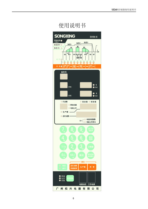
运转及设定时规范表示有时会有不一致的时候,请特别注意。
⑦CYCLE显示窗口(00~99): 运行中的电流显示选择部分(请参照H1~3:⑨、⑫)的通电时间显示。 设定中各个时序程序的时间显示。 ⑧kA.%显示窗口: 运行中的电流显示选择部分,请参照(H1~3:⑨、⑫)的焊接电流等显示。 设定中各电流设定值等显示。 ⑨加压SV指示灯: 加压SV指示灯亮灯时,电磁阀(SV)序号在电流显示窗口显示。 ⑪时序区间/异常项目指示灯: 运行中及设定中、时序区间显示。 运行停止、CYCLE电流显示及通电1~3段间显示。 如果异常指示灯亮时,则表示此为这个异常的项目显示指示。 ⑫异常指示灯: 异常发生显示。异常的内容⑫在这个异常的项目显示。 ⑬打点数、阶段、附加功能显示窗口: 在运行中,当有计数器使用时的打点数值显示。 阶段指示灯亮时,阶段电流制御的阶段序号显示。
线圈端用束带固定
二次导体
请将感应线圈尾部铺平, 并用 束线带包扎固定之, 并避免让 中间的缝隙发生 线圈标准安装示意图 线圈不良安装示意图
3
SKM6 控制器使用说明书
2.各部名称及接线
2-1正面面板的概要说明
4 9 11
12 13 6
7
8
14
15 16
17 5 18 19 20
3
21
2
1
4
SKM6 控制器使用说明书
注意:外部端子30B-42焊接“入—切”断路时, “模式”指示灯闪烁来指示当前灯的状态,且不能通电焊接。
③设定/运行选择键: 设定模式及运行模式选择用。按一次设定及运行交替切换。 ④焊接电源指示灯: 焊接电源供给时,亮灯显示。 当SCR触发控制的端子台3、4及5号有焊接电源输入时,焊接电源指示灯亮。 要接触端子台时请先将主电源确认关闭。 ⑤数字(0~9确定)键; 规范、程序阶段、计数器及附加功能参数输入时使用。 ⑥规范显示窗口【0,1~15(31)】 选择运行及设定时规范显示。 当运行规范采用外部启动选择时,小数点亮灯。
华控RSM 智能模块及其分布式系统(SDS)使用手册.

华控RSM 智能模块及其分布式系统(SDS使用手册北京华控技术有限责任公司北京华控技术有限责任公司1目录系统简介............................................................................................................................................ . (1)第一部分华控RSM 智能模块及其分布式系统 (1)1 系统组成............................................................................................................................................ ....................................... 12 系统工作方式........................................................................................................................................ (2)第二部分系统硬件配置和智能模块 (3)1 上位机的选用硬件配置工作温度和安装方式. ............................... ................................ ................................ (4)4.1.4 模块的供电................................ ................................ ................................ ................................ ........ ........................ .. 44.1.5 面板指示灯RSM 智能模块及分布式系统23.1 CBSM软件的运行............................................................................................................................................ . (28)3.2 组态............................................................................................................................................ .. (28)3.2.1 添加节点............................................................................................................................................ (28)3.2.2 上位机组态............................................................................................................................................ .. (29)3.2.3 RSM01—RSM08节点的组态 (29)4 DDE服务器的启动及使用............................................................................................................................................ .. 334.1 华控DDE 服务器的接口信息 (33)4.1.1 DDE 接口信息............................................................................................................................................ (33)4.1.2 Network DDE接口信息.............................................................................................................................................344.2 在VB 中应用华控DDE 服务器软件 (34)4.2.1 基本概念............................................................................................................................................ (34)4.2.2 应用实例............................................................................................................................................ (35)4.3 华控DDE 服务器软件在其它应用程序中的应用 (35)北京华控技术有限责任公司1华控RSM 智能模块及其分布式系统(SDS使用手册华控RSM 智能模块及其分布式系统(SDS的特点系统简介CAN是属于现场总线的范畴IEC°´ÕÕSP ÏÖ³¡×ÜÏßÊÇ“在制造/过程现场和安装在生产控制室先进自动化控制装置中所配置的主要自动化装置之间的一种串行数字通信链路”ÏÖ³¡×ÜÏßϵͳ¾ß±¸¼àÊÓ¿ØÖÆÄÜÁ¦Ç¿ÊµÊ±ÏìÓ¦ÐÔºÃͨÐÅÐ-Òé¼òµ¥µÈÓŵãÔÚ¹ú¼ÊÉÏÄ¿Ç°ÓÃÓÚ×Ô¶¯»¯¿ØÖÆÁìÓòµÄCAN 总线产品已占第二位CAN 通信卡通信媒体MMIÈçͼ1-1ÆäͨÐÅÐ-Òé·ûºÏÃÀ¹úHONEYWELL 公司SDS CAN2.0标准我们的模块不是一个简单的远程I/O模块而每个模块上位机(内插CAN 通信卡通信媒体系统软件:组态与驱动RSM 智能模块及分布式系统2都是在一个嵌入式实时多任务的内核管理下周期性工作具体见RSM 智能模块部分按组态要求定时地向上发送和取得数据保证了调节的实时性因此本系统的工作方式是其它模块不能比拟的以避免电缆反射波1总线型拓扑结构总线最大长度为40m两节点间最短距离0.1m说明总线长度可以加长1所示1波特率最大总线长度 1Mbps 40m 250Kbps 270m 125bps 530m 100Kbps620m 50Kbps13km 10Kbps 6Óû§¿ÉÒÔÑ¡ÓÃ1mm 2的优质铜芯双绞线则应选用带屏蔽层的护套线应在线路的两个终端模块各接入一个120ÒÔ¼õÉÙÐźŷ´Éä¿É²åÉÏ°åÄÚÖն˵ç×è¶Ì·¿éµ±Í¨ÐŲ忨λÓÚÏß·µÄÖмäʱ×ÜÖ®µ±Í¨ÐÅÏß·ÔÚ2km以上时可适当加大终端电阻的阻值北京华控技术有限责任公司3第二部分系统硬件配置和智能模块1 上位机的选用至少需要下列软硬件配置l M icrosoft Windows 95/98/ NT/2000操作系统 l 586以上工控机及其兼容机建议使用32M 以上的内存l 10M 可用硬盘空间 l SVGA 显示卡2 C A N 通信卡的选用华控公司也是各种专用CAN 通信卡的专业生产厂家其产品包括HKHK HK HK以上这几种CAN 卡都能很好的服务于由华控RSM 智能模块组成的系统带屏蔽双绞线底层软件固化于片内看门狗功能保证系统具有自恢复能力CAN 通信方式最多可有4台上位机运行通信协议采用CAN2.0A 协议4. 1. 2 模块地址和通信速率的设置模块地址和通信速率通过模块内拨码开关设定CAN 通信的速率和距离的关系请参照附表CAN 通信的最高通信速率可达1Mbit/sÎÒÃÇÌṩ¸øÓû§µÄͨ¹ý²¦Â뿪¹ØÉ趨µÄͨÐŲ¨ÌØÂÊΪ4档100K500K用户可以根据现场实际通信距离的长度在订货时提出更改要求bps ÒÔÉÏΪ²Î¿¼Êý¾ÝͨÐÅÏßÏß¾¶µÈÓйØÒ»°ãͨÐÅËÙ¶ÈÆ«µÍÑ¡ÔñΪ¼ÑRSM 智能模块及分布式系统4拨码开关SW1的设置如下所述6位为智能模块通信地址设定开关第一位为最低位633为上位机通信地址用户使用时SW1的任何一位开关拨向位置该位为即无效OFF1ͼ2-1中,a 开关右侧所标注数值是各位对应的十进制值例2644²¦Â뿪¹ØSW1的7RSM 模块波特率一般在出厂时设置分为4档250K20Kef用户如果有特殊需要我们可按用户要求设置80mm长厚智能模块的工作温度257085智能模块的安装方式24V DC4. 1. 5 面板指示灯红色为电源指示灯COM ÉÁ˸ΪͨÐÅÕý³£Ã»ÓÐÌØÊâ˵Ã÷µÄÖ¸±ê¾ùΪµäÐÍÖµ4. 2. 1 R S M 01隔离型模拟量输入模块4. 2. 1. 1 模块工作原理RSM01隔离型模拟量输入模块设有8路双端模拟量输入通道RSM01在工作时仪表放大器经光耦隔离送入单片机平滑化后通过CAN 通信接口将数据送至上位机型号20mA电流输入模块图 2-1 拨码开关设置a 1 2 4 8 1632b c20K100K250K500KSW1 SW1 SW1 SW1d e f g北京华控技术有限责任公司5RSM01-CI10型 0输入通道数模拟信号输入范围05V -CI型20mA-CI10型10mAd12 位e输入阻抗10M250500采样速率8通道/次输入共模电压4V i -CV 型过压CPU 看门狗定时时间通信方式CAN通信波特率CAN通信距离10km d CAN 通信方式选择20Kbps 250Kbps64个4.2.1.2.4电源部分 a. 供电电压5%b.隔离电压信号输入24VDCX1可拔插接线端子 SW1电源指示发光二极管H2X2接线端子定义如图2-3所示CH7+:模拟量输入通道0CH7-:模拟量输入通道0 C H 1+ C H 1C H 3+ C H 3C H 5+ C H 5RSM 智能模块及分布式系统64.2.1.4.2 接线方法a.RSM01-CV 电压输入方式输入信号负端接到CH–端图 2-4 RSM01-CV电压信号接线图 b.RSM01-CI 电流输入方式输入信号正端接到CH+±äËÍÆ÷¹©µçÓÉÓû§Ìṩ图 2-5 RSM01-CI 四线制变送器接线图 c.RSM01-CI 电流输入方式输入信号正端接到CH–±äËÍÆ÷¹©µçÓÉÓû§Ìṩ图 2-6 RSM01-CI 两线制变送器接线图 d.RSM01-CI10电流输入方式输入信号正端接到CH+±äËÍÆ÷¹©µçÓÉÓû§Ìṩ图 2-7 RSM01-CI10 四线制变送器接线图 4. 2. 2 R S M 01C 隔离型模拟量输入模块4. 2. 2. 1 模块工作原理RSM01C 隔离型模拟量输入模块设有8路模拟量输入通道RSM01C在工作时仪表放大器经光耦隔离送入单片机平滑化后通过CAN通信接口将数据送至上位机北京华控技术有限责任公司7X1电源24V信号输入端子通信接口X2辅助电源图2-9 RSM01C接线端子示意图4. 2. 2. 2 主要技术指标4.2.2.2.1模拟信号输入部分 a RSM01C 型 4 输入通道数模拟电流输入范围20mA由辅助电源供电A/D分辨率模拟电流输入精度0.1% f 250 采样速率8通道/次输入限流保护CPU看门狗定时时间通信方式CAN通信波特率CAN通信距离10km d CAN 通信方式选择20Kbps 250Kbps 通信站点数量 60 f 64个4.2.2.2.4电源部分a 24V DC 隔离电压信号输入功耗50mA4. 2. 2. 3主要元器件位置图如图2-8所示X2CAN通信地址及波特率设置开关H1CAN 通信指示发光二极管 4. 2. 2. 4 接线端子定义4.2.2.4.1 RSM01C模块X1CH7+:模拟量输入通道0CH7-:模拟量输入通道0RSM 智能模块及分布式系统8RSM01C 接两线制变送器输入信号负端接到CH–端如图2-1016位分辨率AD 转换器可编程放大器周期性地将输入的毫伏电压信号经AD 转换单片机对输入数据经过滤波及平滑化处理后4. 2. 3. 2 主要技术指标4.2.3.2.1模拟信号输入部分 a RSM02型小信号电压输入模块 b 2 路c39mV/0.156V/0.625V/2.5Vd 16 位e输入阻抗g 10 次/秒 h 24V 4.2.3.2.2控制部分 a 51系列单片机 b 1.4秒4.2.3.2.3通信部分 a CAN b 5k/10k/20k/50k/100k/250k/500k/1Mbps c波特率设置100Kbps500Kbps四种波特率e通信站地址设置供电电压5%b1000V DC (模块供电通信端口三者之间均隔离c24VDCX1可拔插接线端子SW1北京华控技术有限责任公司9H1CAN 通信指示发光二极管4. 2. 3. 4 接线端子定义 4.2.3.4.1RSM02模块X1 模块24V 供电电源正极地为未用端子4.2.3.4.2接线方法输入信号正端接到CH+Èçͼ2-1324位分辨率AD 转换器可编程放大器周期性地将输入的热电偶或毫伏电压信号经输入端低通滤波光电隔离后送入单片机通过CAN 接口通信接口送至上位机4. 2. 4. 2 主要技术指标4.2.4.2.1模拟信号输入部分 a RSM02A 型热电偶输入模块 b 4路 c. 输入信号类型J 型 -2101200/ T 型 -200400/ R 型1750/ B 型 6501800e. 输入信号范围25mV/100mV f. 热电偶冷端补偿精度124 位h. A/D转换精度0.05% i. 输入阻抗图2-14 RSM02A元器件位置图电源24V信号输入端子通信接口X2X1图2-12 RSM02接线端子示意图RSM 智能模块及分布式系统10j. 转换速率4通道/次断线识别CPU看门狗定时时间通信方式CAN通信波特率CAN通信距离10km d CAN 通信方式选择20Kbps 250Kbps通信站点数量 60 f 64个 4.2.4.2.4电源部分 a 24VDC隔离电压信号输入功耗 40mA 4. 2. 4. 3 主要元器件位置如图2-14所示X2CAN通信地址及波特率设置开关H1CAN 通信指示发光二极管 4. 2. 4. 4 接线端子定义 4.2.4.4.1 RSM02A模块X1 模块24V 供电电源正极地为未用端子4.2.4.4.2接线方法RSM02A 热电偶输入方式输入信号负端接到CH–端图 2-16 RSM02A热电偶输入接线图电源24V信号输入端子通信接口X2X1图2-15 RSM02A 接线端子示意图北京华控技术有限责任公司114. 2. 5 R S M 03A 隔离型热电阻输入模块4. 2.5. 1 模块工作原理RSM03A 隔离型智能模块设有4路热电阻输入通道RSM03A隔离型热电阻输入模块采用的是高精度的A/D转换器可编程放大器及精度校准功能连接在输入端的热电阻在200µÃµ½µÄµçѹÐźž-ÊäÈë¶ËµÍͨÂ˲¨¾-¹âñî¸ôÀëËÍÈ뵥Ƭ»úͨ¹ýCAN 通信接口将温度结果传送至上位机显示4. 2.5. 2 主要技术指标4.2.5.2.1模拟信号输入部分 a RSM03A 型热电阻输入模块 b 4路 c3线制RT D 类型-200850/Pt100-50150/Cu100恒流源采集分辨率采样速率4通道/次断线识别断信号负端显示量程下限输入过压保护24VjPt50和Pt1000.54.2.5.2.2控制部分 a 51系列单片机b 1.4秒4.2.5.2.3通信部分a CANb 5k/10k/20k/50k/100k/250k/500k/1Mbps c波特率设置100Kbps500Kbps四种波特率e通信站地址设置供电电压5%b1000V DC (模块供电通信端口三者之间均隔离 c 24VDC X1可拔插接线端子 SW1电源指示发光二极管H2X2接线端子定义如图2-18所示:电源24V信号输入端子通信接口X2X1图2-18 RSM03A 接线端子示意图RSM 智能模块及分布式系统12+24V:模块供电电源(24VDC 正极地:模块供电电源(24VDC 负极 COMi+:接CAN 通信信号正端 COMi-:接CAN 通信信号负端COMo+:接CAN 通信网络终端匹配电阻 COMo-:接CAN 通信网络终端匹配电阻CH0CH3热电阻输入端 CH0CH3热电阻输入端 GND为未用端子 4.2.5.4.2 接线方法RSM03A 热电阻输入不同线制的接线方法如图2-19¶þÏßÖƵĽÓÏß·½Ê½Ö»ÊÊÓÃÓÚ½ÓÏ߱Ƚ϶̵ij¡ºÏ4. 2. 6 R S M 04隔离型脉冲输入计数器模块4. 2. 6. 1 模块工作原理RSM04模块设有2路脉冲量输入可滤除窄于设定脉宽的干扰脉冲将输入的脉冲信号经输入端信号调理后在单片机的控制下处理若用户的设备输出的脉冲为负脉冲再送入本模块进行滤波计数用户应了解输入的有效正脉冲信号的宽度Tin ÓÈÆäÐèÈ·ÈÏ×îÕ-µÄÂö¿íΪ¶àÉÙTp 是一个以微秒为单位的整型值当输入脉冲的上升沿到来时对输入脉冲的宽度进行判断输入的脉冲可以被正常计数所以设置参数Tp 时应满足2ÔÚÕâÀïÓÐÒ»ÖÖÌØÀýÇé¿ö»á±»ÈÏΪÊÇÓÐЧÂö³åÓèÒÔ¼ÆÊý设Tp=90S 110S输入 1 2 3 4 5 图2-20 信号输入图中的脉冲1可被正常计数被正确滤除被误认为有效脉冲而被计数可通过对Tp 稍加调整来解决对于干扰信号将1个有效正脉冲变为两个正脉冲时 4. 2. 6. 2 主要技术指标4.2.6.2.1脉冲信号计数输入部分CH0+ CH0北京华控技术有限责任公司13a RSM04-C5型 015V 脉冲量计数模块RSM04-C24型 0´¥µã¹©µçµçÔ´ÓÉϵͳ24V 提供b -C5型 2路-C15型 2路-C24型 2路 -CC型 2路c <200 KHzd -C5型高电平4V8mA 低电平1V0.5mA 电流电流-C24型高电平21V 8mA 低电平1V 0.5mA1断开为逻辑e16位f 0.01%g 265mS 4.2.6.2.2控制部分 a 51系列单片机 b 1.4秒 4.2.6.2.3通信部分a CAN b 5k/10k/20k/50k/100k/250k/500k/1Mbps c波特率设置100Kbps500Kbps四种波特率e通信站地址设置供电电压5%b1000V DC (-C5型模块供电通信端口三者之间均隔离信号输入-C24型模块供电通信端口三者之间均隔离功耗30mA4. 2. 6. 3 主要元器件位置如图2-21所示X2CAN通信地址及波特率设置开关H1CAN 通信指示发光二极管 4. 2. 6. 4 接线端子定义4.2.6.4.1 RSM04模块X1RSM 智能模块及分布式系统14COMi-:接CAN 通信信号负端COMo+:接CAN 通信网络终端匹配电阻 COMo-:接CAN 通信网络终端匹配电阻CH0和CH1接脉冲量输入通道0和1信号负端 NC:未用端子4.2.6.4.2 接线方法输入信号的接线方法如图2-23¿ÉÊä³ö120mA 电流信号通过CAN 通信接口将输出数据送入单片机后信号类型可通过跳线器选择电压或电流信号输出型号5V电压/4输出通道数输出范围5V电流方式 4带载能力5K400D/A分辨率输出建立时间输出精度0.1% hCPU看门狗定时时间通信方式CAN通信波特率CAN通信距离10km d CAN 通信方式选择20Kbps250Kbps通信站点数量 60 f 64个图2-24 RSM05元器件位置图北京华控技术有限责任公司154.2.7.2.4电源部分 a 24V DC隔离电压电压方式模块供电通信端口三者之间均隔离h电压方式 24VDC160mA4. 2. 7. 3 主要元器件位置如图2-24所示X2CAN通信地址及波特率设置开关H1CAN 通信指示发光二极管 4. 2. 7. 4 接线端子定义4.2.7.4.1 RSM05模块X1电流输出端OUT0接摸拟量信号输出端(见接线方法 GND½ÓÏß·½·¨ÊDz»Í¬µÄXF5的不同跳线方式来选择表 2-2 通道号0通道1通道2通道3通道X1X2图2-25 RSM05接线端子示意图24VO U T 0G N D电流输出负载+ –图2-26RSM05模拟输出接线图RSM 智能模块及分布式系统16跳线器 XF2 XF3 XF4 XF5 输出电压信号输出电流信号4. 2. 8 R S M 06隔离型开关量输入模块4. 2. 8. 1 模块工作原理RSM06模块设有8路隔离开关量输入通道将输入的电压经输入端信号调理后在单片机的控制下4. 2. 8. 2 主要技术指标4.2.8.2.1开关量信号输入部分 a RSM06-C5型 015V 开关量输入模块RSM06-C24型 0输入通道数通道间隔离输入信号阈值电流电流-C15型高电平14V5mA 低电平1V0.5mA电流电流d100Hz 4.2.8.2.2控制部分 a 51系列单片机 b 1.4秒 4.2.8.2.3通信部分 a CAN b 5k/10k/20k/50k/100k/250k/500k/1Mbps c波特率设置100Kbps500Kbps四种波特率 e通信站地址设置供电电压5%b1000V DC (模块供电通信端口三者之间均隔离c24VDCX1可拔插接线端子 SW1电源指示发光二极管H2北京华控技术有限责任公司17图2-30 RSM06C元器件位置图4. 2. 8. 4 接线端子定义 4.2.8.4.1 RSM06模块X1 7信号正端CH0CH7接开关量输入通道0RSM06C模块在工作时经光耦隔离送入单片机通过CAN 通信接口将开关量状态输入信号传送至上位机型号输入通道数触点信号输入逻辑关系1断开为逻辑d100Hz 4.2.9.2.2控制部分a 51系列单片机b 1.4秒 4.2.9.2.3通信部分 a CAN b 5k/10k/20k/50k/100k/250k/500k/1Mbps c 波特率设置100Kbps500Kbps四种波特率e通信站地址设置24V DC1000V DC (模块供电和通信端口之间隔离RSM 智能模块及分布式系统18c. 功耗30mA 4. 2. 9. 3 主要元器件位置如图2-30所示X2CAN通信地址及波特率设置开关H1CAN 通信指示发光二极管 4. 2. 9. 4 接线端子定义 4.2.9.4.1 RSM06模块X1 7信号正端CH0CH7接开关量输入通道0¾ßÓÐCAN 现场总线通信功能的隔离型智能开关量输出模块通过CAN 通信接口将输出数据送入单片机后4. 2. 10. 2 主要技术指标4.2.10.2.1开关量信号输出部分 a RSM07-C5型 0TTL15V 开关量输出模块RSM07-C24型 0 开关量输出通道数开关量输出形式-C5型高电平2.8V 1mA 低电平0.5V10mA 电流电流-C24型高电平18V1mA低电平0.7V 10mA输出信号建立时间北京华控技术有限责任公司19图2-33 RSM07元器件位置图a 51系列单片机b 1.4秒 4.2.10.2.3通信部分 a CAN b5k/10k/20k/50k/100k/250k/500k/1Mbps c波特率设置100Kbps500Kbps四种波特率 e 通信站地址设置24V DC1000V DC (模块供电与通信端口之间隔离 d24VDCX1可拔插接线端子 SW1电源指示发光二极管H2X2接线端子定义如图2-34所示:+24V:模块供电电源(24VDC 正极地:模块供电电源(24VDC 负极 COMi+:接CAN 通信信号正端 COMi-:接CAN 通信信号负端COMo+:接CAN 通信网络终端匹配电阻 COMo-:接CAN 通信网络终端匹配电阻 CH0CH7接开关量输出通道07信号负端NC:未用端子4.2.10.4.2接线方法如图2-35,CH+端接到负载正端端接到负载负端RSM 智能模块及分布式系统20图2-36 RSM07B元器件位置图4. 2. 11 R S M 07B 隔离型开关量输出模块 4. 2. 11. 1 模块工作原理RSM07B 模块设有8路开关量输出通道RSM07B 模块在工作时经光耦隔离后输出型号开关量输出通道数通道间隔离输出形式输出逻辑关系输出0 断开f µçѹ30V DC 电流100mA g µ¼Í¨ 1mSCPU看门狗定时时间通信方式CAN通信波特率CAN通信距离10km d CAN 通信方式选择20Kbps250Kbps通信站点数量 60 f 64个 4.2.11.2.4电源部分a. 供电电压5%b.隔离电压信号输出24VDCX1可拔插接线端子 SW1电源指示发光二极管H2X2接线端子定义如图2-37所示:+24V:模块供电电源(24VDC 正极地:模块供电电源(24VDC 负极 COMi+:接CAN 通信信号正端 COMi-:接CAN通信信号负端COMo+:接CAN 通信网络终端匹配电阻 COMo-:接CAN 通信网络终端匹配电阻 CH0CH7接开关量输出通道07信号负端信号输入端子X1 X2电源24V通信接口图2-37 RSM07B接线端子示意图北京华控技术有限责任公司21NC:未用端子4.2.11.4.2接线方法如图2-38,RSM07CH ¹¤×÷µçÔ´ÐèÍâ½Ó输出接线图注意如继电器应如图所示接保护二极管4. 2. 12 R S M 08隔离型继电器输出模4. 2. 12. 1 模块工作原理RSM-08模块设有4路具有自保持功能继电器输出通道通过CAN 通信接口将输出数据送入单片机后4. 2. 12. 2 主要技术指标 4.2.12.2.1继电器输出部分 a RSM08型继电器输出模块 b 4 路 c 2c (触点输出状态自保持触点控制1断开 e DC250V AC /0.5A注意应增加防护盒否则将危及人身安全触点寿命105 次 4.2.12.2.2控制部分 a 51系列单片机 b 1.4秒 4.2.12.2.3通信部分 a CAN b 5k/10k/20k/50k/100k/250k/500k/1Mbps c波特率设置100Kbps500Kbps四种波特率 e通信站地址设置供电电压5%b模块供电与通信端口之间隔离耐压1000V DC信号输出端与通信端口之间隔离耐压2500V DC c 24VDC图2-39 RSM08元器件位置图RSM 智能模块及分布式系统224. 2. 12. 3 主要元器件位置如图2-39所示X2CAN通信地址及波特率设置开关H1CAN 通信指示发光二极管4. 2. 12. 4 接线端子定义4.2.12.4.1 RSM08模块X1RL0_4RL1_4RL2_4RL3_4RL_1和RL_2为触点1的输出端, RL_3和RL_4为触点2的输出端. aÈçͼ2-41用户也可以用继电器的两个触点控制两个动作相同的设备c如图2-43当用户外接感性负载时, 应在负载两端增加与负载相适应阻容X1电源24V信号输入端子通信接口X2北京华控技术有限责任公司234. 2. 13 R S M 08A 隔离型继电器输出模4. 2. 13. 1 模块工作原理RSM-08A 模块设有4路具有自保持功能继电器输出通道通过CAN 通信接口将输出数据送入单片机后4. 2. 13. 2 主要技术指标 4.2.13.2.1继电器输出部分 a RSM08A 型继电器输出模块 b 4 路 c 1c (触点输出状态自保持 g 吸合0 触点容量30VDC /2AAC Èç¹ûÓû§Íâ½Ó220V 交流设备时并注明强电标志f. 触点寿命105 次 4.2.13.2.2控制部分 a 51系列单片机 b 1.4秒 4.2.13.2.3通信部分 a CAN b 5k/10k/20k/50k/100k/250k/500k/1Mbps c 波特率设置100Kbps500Kbps四种波特率 e通信站地址设置供电电压5%b模块供电与通信端口之间隔离耐压1000V DC信号输出端与通信端口之间隔离耐压2500V DC c 24VDCX1可拔插接线端子 SW1电源指示发光二极管H2X2接线端子定义如图2-46所示:+24V:模块供电电源(24VDC 正极地:模块供电电源(24VDC 负极 COMi+:接CAN 通信信号正端 COMi-:接CAN 通信信号负端COMo+:接CAN 通信网络终端匹配电阻图X1电源24V输入信号端子通信接口X2RSM 智能模块及分布式系统24COMo-:接CAN 通信网络终端匹配电阻 RL0_1继电器0接线端子 RL1_1继电器1接线端子 RL2_1继电器2接线端子 RL3_1继电器3接线端子NC:未用端子 4.2.13.4.2 接线方法RSM08A 继电器模块输出接线方法如下RL_1和RL_2为继电器的触点输出端如图2-47Èçͼ2-48H K C A N 10S 智能通信卡符合CAN2.0A 规范最高通信速率DOSÈ·±£Êý¾Ý°²È«ÐÔH K C A N 20C 非智能通信卡符合CAN2.0A 规范北京华控技术有限责任公司25最高通信速率DOS1Mbit/s运行环境1Mbit/s运行环境例如我们的CAN10S 通信卡就适合在用户对丢帧现象要求又极苛刻时使用性价比极高HK-CAN20C 非智能CAN 总线通信板相信对我们 CAN 卡的使用已了然于胸a如果您的 CAN卡与我们的RSM 模块一同工作所以上面提到的磁盘将没有任何作用如果您的PC 机中IRQ11IRQ15等中断都已经被其它设备占用这种状况会有两种情形即插即用由于各PC 的具体设置不尽相同首先按 DEL 键进入 BIOS 其次将 Resources Controlled By½« IRQ-10IRQ-12与CAN 卡的IRQ 跳线值保持一致项选成 legacy ISA 最终并重新启动PC 完成所需设置说明您的机器上一同使用的设备太多腾出相应资源RSM 智能模块及分布式系统265. 1. 2 通信线缆的选用对于一般环境若现场干扰较大但此时应注意屏蔽层的良好接地若屏蔽层接地欠妥具体细则请参见相关手册中关于计算机接地要求的部分应在线路的终端串接一120ʹÏß·ÐγɻØ·ÔÚCOMo+和COMo 之间接CAN 通信网络终端匹配电阻¶ÔµçÔ´ÒªÇóÊ×ÏÈÊÇÎȶ¨ÎÞÔÓ²¨Æä´ÎÒÔ½â¾ö³¤¾àÀëÊäµçµÄѹ½µµÄÎÊÌâRSM 模块本身不防水l 防雷 l 防爆场合 l 当RSM08和RSM08A 用于控制220V 交流设备时并注明强电标志否则将危及人身安全北京华控技术有限责任公司27第三部分系统软件使用说明华控CAN 总线软件工具是运行在 Windows¸ÃÈí¼þÓÃÓÚÍê³É»ª¿Ø¼¼Êõ¹«Ë¾ÑÐÖƵĻùÓÚCAN 总线的智能模块的组态工作及数据通信工作其倾注了公司技术人员的心血在运行HUCE.EXE 和HKDDEServre.exe 这两个程序之前随软件赠送此加密锁的安装我们为您能支持我们的工作而表示感谢华控软件的安装通过的方式首先然后在Windows 或WinNT 的菜单中选则R命令打开[O]X:\setup这里确定这时在屏幕中央出现CBSM 的安装程序界面在屏幕的右下方出现一提示框安装向导通过的提示图 3-1 安装程序界面RSM 智能模块及分布式系统。
M-System R6N-TS2 热电偶输入模块说明书

BEFORE USE ....Thank you for choosing M-System. Before use, please check contents of the package you received as outlined below.I f you have any problems or questions with the product, please contact M-System’s Sales Office or representatives.■PACKAGE INCLUDES:Thermocouple input module (1)■MODEL NO.Confirm Model No. marking on the product to be exactly what you ordered.■INSTRUCTION MANUALThis manual describes necessary points of caution when you use this product, including installation, connection and basic maintenance procedures.The unit is programmable using the PC Configurator Soft-ware. For detailed information on the PC configuration, refer to the R6CON users manual. The R6CON PC Con-figurator Software is downloadable at M-System’s web site: http://www.m-system.co.jpPOINTS OF CAUTION■CONFORMITY WITH EU DIRECTIVES• The equipment must be mounted inside a panel.• Insert a noise filter for the input and communication line connected to the unit. NEC TOKIN Model ESD-SR-250 or equivalent is recommended.• The actual installation environments such as panel con-figurations, connected devices, connected wires, may af-fect the protection level of this unit when it is integrated in a panel system. The user may have to review the CE requirements in regard to the whole system and employ additional protective measures to ensure the CE conform-ity.• Install lightning surge protectors for those wires connect-ed to remote locations.■HOT INSERTION/REMOVAL OF MODULES• Removing or replacing modules does not affect other mod-ules on the same backplane. It is possible to replace them without removing the power supply. However, replacing multiple modules at once may greatly change line voltage levels. We recommend that you replace them one by one.■GENERAL PRECAUTIONS• Do NOT set the switches while the power is supplied. The switches are used only for maintenance without the power.■ENVIRONMENT• Indoor use.• When heavy dust or metal particles are present in the air, install the unit inside proper housing with sufficient ventilation.• Do not install the unit where it is subjected to continuous vibration. Do not subject the unit to physical impact.• Environmental temperature must be within -10 to +55°C (14 to 131°F) with relative humidity within 30 to 90% RH in order to ensure adequate life span and operation.■WIRING• Do not install cables close to noise sources (relay drive cable, high frequency line, etc.).• Do not bind these cables together with those in which noises are present. Do not install them in the same duct.■AND ....• The unit is designed to function as soon as power is sup-plied, however, a warm up for 10 minutes is required for satisfying complete performance described in the data sheet.COMPONENT IDENTIFICATION INSTALLATIONMount the unit on the base (model: R6N-BS).EXTERNAL VIEWS• Front View (cover opened)• Side View Operating Mode■INDICATOR LEDID COLOR FUNCTIONPower OFF Power supply is offGreen ON Power supply is on.Status OFF Standing by (at the startup)or communication errorGreen ON Normal communicationGreen blink Configuration modeRed ON DIP switch errorRed blink2 sec. intervalParameter errorRed blink0.5 sec. intervalBurnout■MODULE ADDRESSModule address is selectable between 0 and 31. Choose 0 or 16 with SW1 for offsetting the address selected with SW2 (0 to F, hexadecimal).The module’s slot position on the base and the module ad-dress are not necessarily correlated.ADDRESS SW1SW2ADDRESS SW1SW2 00016160101171612021816230319163404201645052116560622166707231678082416890925169100A2616A110B2716B120C2816C130D2916D140E3016E150F3116F ■OPERATING MODE(*) Factory setting• Thermocouple TypeT/CINPUT 1INPUT 2SW3SW3123456K (CA) (*)E (CRC)■■J (IC)■■T (CC)■■■■B (RH)■■R■■■■S■■■■C (WRe 5-26)■■■■■■Use PC Configurator Software (model: R6CON) to set N, U, L, P (Platinel II) and PR thermocouples.■ = ON, Blank = OFF • BurnoutBURNOUT SW3-7Upscale (*)Downscale■■ = ON, Blank = OFF • Configuration ModeCONFIGURATION MODE SW3-8DIP SW (*)PC■■ = ON, Blank = OFFTERMINAL CONNECTIONSConnect the unit as in the diagram below or refer to the connection diagram on the side of the unit. ■EXTERNAL DIMENSIONS unit: mm (inch)*Screwdriver stem diameter: 6 mm (.24”) or less■CONNECTION DIAGRAMINPUT 1INPUT 2• Unused Input ChannelsClose across the unused input terminals as shown below . (Choose K (CA) thermocouple for unused channels.)ShortIf unused input terminals are not short-circuited, status in-dicator LED blinks in red (0.5 sec. cycle), and a burnout flag is set in the PLC or the host device.WIRING INSTRUCTIONS■SCREW TERMINAL Torque: 0.5 N·m■SOLDERLESS TERMINAL unit: mm (inch)Refer to the drawing below for recommended ring tongue terminal size. Spade tongue type is also applicable.Solderless terminals with insulation sleeve do not fit.Applicable wire size: 0.2 – 2.5 mm 2PC CONFIGURATORWith configurator software, settings shown below are available.Refer to the software manual of R6CON for detailed operation.■CHANNEL INDIVIDUAL SETTINGPARAMETER AVAILABLE RANGE DEFAULT SETTINGK (CA)Sensor type K (CA)E (CRC)J (IC)T (CC)B (RH)RSC (WRe 5-26)NULP (Platinel II)(PR)Lower range value Depends on sensor type0.00 (degC)Upper range value Depends on sensor type0.00 (degC)Fine zero adjustment -320.00 to +320.00 (%)0.00 (%)Fine gain adjustment -3.2000 to +3.2000 1.0000Scaled range Zero -32000 to +320000Scaled range Span -32000 to +3200010000Burnout Upscale, Downscale Upscale■CHANNEL BATCH SETTINGPARAMETER AVAILABLE RANGE DEFAULT SETTING0.0 – 99.9 (sec.) 1.0 (sec.)Loss of internal bus commu-nication detection timeConversion rate250, 500 (msec.)500 (msec.) Temperature unit degC, degF, K degCCJC ON, OFF ONLimit -15 to +115%-15 to +115%Scaled range Zero / Span。
斯莱姆斯曼系列钢铁工作台说明书

SSWT36, SSWT48Stainless Steel Work Table Assembly InstructionsMax Weight Capacity = 330 LbsREAD ALL INSTRUCTIONS AND WARNINGS BEFORE USING THIS PRODUCT.This manual provides important information on proper operation & maintenance. Every effort has been made to ensure the accuracy of this manual. These instructions are not meant to cover every possible condition and situation that may occur. We reserve the right to change this product at any time without prior notice.IF THERE IS ANY QUESTION ABOUT A CONDITION BEING SAFE OR UNSAFE, DO NOT USE THIS PRODUCT!DO NOT RETURN THIS PRODUCT TO THE RETAILER - CONTACT CUSTOMER SERVICE. If you experience a problem, have questions or need parts for this product, visit our website or call Customer Service at 1-888-287-6981, Monday-Friday, 8 AM - 4 PM Central Time . A copy of the sales receipt is required.KEEP MANUAL, SALES RECEIPT & APPLICABLE WARRANTY FOR REFERENCEPARTS LISTCheck all packaging materials for any small parts that may have come loose during shipping.Before assembly, locate and identify all parts.Table Top - 1 PieceUnder Shelf - 1 PieceLegs - 4 PiecesSet Screws - 16 PiecesHex Key - 1 PieceFig 3 Fig 4 Fig 2 Fig 1Fig 5ASSEMBLY INSTRUCTIONWARNING: BE PREPARED FOR TEAM LIFT WHEN ASSEMBLING/MOVING HEAVY TABLE.WARNING: SHARP EDGES CAN CAUSE INJURY. USE CAUTION WHEN ASSEMBLING/MOVING TABLE.WARNING: DO NOT SIT OR STAND ON TABLE OR SHELF.1. Place the under shelf on it’s side on the floor.2. One by one, insert each leg into the corner socket of the under shelf [Fig.1]3. Use set screws to loosely attach the under shelf to the legs, approx. 7 inches from floor.[Fig.2]4. Stand table upright [Fig.3]5. Position the table top onto the legs, ensuring each leg is firmly located in its corresponding corner socket of the table top.[Fig.4]6. Attach the table top using set screws. Ensure the table top is level and securely fixed.[Fig.5]7. Securely tighten all set screws before use.Safety Tips· Use caution when cleaning or handling to prevent risk of injury from exposed metal edges. · Do not overload the table or shelf.Cleaning· Before use, remove protective film then clean the table.· Clean the table using a cleaning agent suitable for use with stainless steel and galvanized surfaces. · Always remove cleaning agent residues, as this can discolor the surface.· Never leave any surface damp as this may cause discoloration. Wipe dry thoroughly. 201703。
FESTO MSE6 能源效率模块说明书
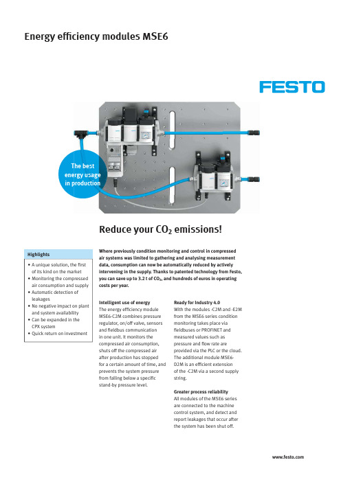
Energy effi ciency modules MSE6Reduce your CO 2 emissions!• A unique solution, the first of its kind on the market • Monitoring the compressed air consumption and supply • Automatic detection of leakages• No negative impact on plant and system availability • Can be expanded in the CPX system• Quick return on investmentHighlightsIntelligent use of energy The energy effi ciency module MSE6-C2M combines pressure regulator, on/off valve, sensors and fi eldbus communication in one unit. It monitors the compressed air consumption, shuts off the compressed air after production has stopped for a certain amount of time, and prevents the system pressure from falling below a specifi c stand-by pressure level.Ready for Industry 4.0With the modules -C2M and -E2M from the MSE6 series condition monitoring takes place via fi eldbuses or PROFINET and measured values such as pressure and fl ow rate areprovided via the PLC or the cloud. The additional module MSE6-D2M is an effi cient extension of the -C2M via a second supply string.Greater process reliabilityAll modules of the MSE6 series are connected to the machine control system, and detect and report leakages that occur after the system has been shut off.Where previously condition monitoring and control in compressed air systems was limited to gathering and analysing measurement data, consumption can now be automatically reduced by actively intervening in the supply. Thanks to patented technology from Festo, you can save up to 3.2 t of CO 2, and hundreds of euros in operating costs per year.2Energy efficiency modules MSE6 – Subject to change – 2020/02Thinking ahead about compressed air supplyMSE6-C2M MSE6-D2MNew standards for clean productionThe topics of resource conservation and energy effi ciency, galvanised by the Paris Climate ProtectionAgreement on CO 2 reduction, are also playing an increasingly important role in industrial automation. Leading companies have already defi ned clear CO 2 targets for their products. Implementing these requires machines that achieve signifi cant energy savings compared to previous models. That is precisely why Festo offers the MSE6 series, a solution that is unique on the market.Energy effi ciency modules MSE6 at a glance2020/02 – Subject to change – Energy efficiency modules MSE63MSE6-E2MWhether with existing or new systems, there are implementation options in almost every applicationEnergy efficiency modules MSE6 can be installed in existing or new systems, wherever the supply of compressed air is to be monitored and controlled.Detecting stand-by states, automatic shut-off or stand-by pressure controlAfter entering machine-specific parameters, the modules recognise when a system is operating or idling. By shutting off the compressed air supply, air cannot be consumed unnecessarily and will not continue to be supplied to any leaks in the machine. Instead, the MSE6-C2M can maintain the output pressure at a previously defined stand-by pressure so that system availability is not impaired.Leakage measurementAfter shutting off the compressed air supply, the system can be checked for pressure leaks. The user therefore first needs to determine if the rate of pressure drops are too high or untypical. By reporting such pressure drops to the PLC, the energy efficiency modules trigger a warning, such as “Possible leakage in the machine. Check required”. This information can then be used by maintenance staff to plan and carry out a service.Condition monitoringEnergy efficiency modules MSE6 can be fully integrated into the machine control system via fieldbus nodes in order to cyclically exchange important energy consumption andavailability data for the system. This data can be transferred from the MSE6-E2M to the cloud via the Festo IoT gateway CPX-IOT, and thus recorded and analysed as long-term measured values.4Energy efficiency modules MSE6 – Subject to change – 2020/02* Assumption: 760 h repair/maintenance ** Depending on the type of leakage:based on a purely statistical worst-case scenario (hole in the tubing) = 70%Return on investment after only 1 to 1½ years*Let’s assume that a machine is operational on 250 days per year based on two shifts and has a compressed air consumption of 2,000 l/min at 6 bar and a leakage rate of 10%. If the compressed air is not shut off during the 4,000 hours of non-production time, 48,000 Nm³ is simply lost. This would be an expensive luxury that would cost you €912 and 3.2 t of CO 2 emissions. On the other hand, by simply reducing the pressure from 6 bar to 2.5 bar, you can save as much as €640 and 2.2 t in CO 2 emissions. And since the energy efficiency modulesincorporate additional functions such as those of the classic pressure regulator MS6-LR, on/off valve MS6-EE, pressuresensors SPAU and flow rate sensors SFAM, the amortisation period is further reduced. Especially if you consider the costs of a cyclical manualleakage detection. The bottom line is that a more conscious use of compressed air pays for itself in less than 1 to 1½ years.Plenty of savings potential* Please note: the following sample calculations are based on realistic assumptions and conditions. The values for your systems may differ and therefore the validity of this information cannot be guaranteed.Possible savings with the module MSE6-C2M*** 1 kWh of electricity produces 0.5 kg CO 2.These figures apply to Germany and may vary in other countries. Source for 2015 figures: German Federal Environment Agency (https://www.umweltbundesamt.de/themen/klima-energie/energieversorgung/strom-waermeversorgung-in-zahlen#Strommix)Possible savings with the modules MSE6-E2M and MSE6-D2M* Assumption: 760 h repair/maintenance ** Depending on the type of leakage *** 1 kWh of electricity produces 0.5 kg CO2.These figures apply to Germany and may vary in other countries. Source for 2015 figures: German Federal Environment Agency (https://www.umweltbundesamt.de/themen/klima-energie/ energieversorgung/strom-waermeversorgung-in-zahlen#Strommix)2020/02 – Subject to change – Energy efficiency modules MSE656Energy efficiency modules MSE6 – Subject to change – 2020/02Proportional pressure regulatorElectric on/off valve(normally open)Integrated pressure sensor (P2)MS pressure gauge (P2)Mounting bracketElectronics housingDC 24V supplyFlow rate sensorInterface for integration into the Festo MS6 seriesStatus display(status device and IOs)Profi net bus node CPX FB342 DI (M12) / 2 DO (M12) /CPX extension port (optional)Energy effi ciency module MSE6-C2MReducing the pressure in stand-by modeP1P22020/02 – Subject to change – Energy effi ciency modules MSE67Control functions• Adjustable regulated output pressure• Automatic pressure reduction without exhausting the system during downtimes• Detecting leaks by evaluating the pressure drop in stand-by mode• Adjustable pressure increase (soft-start)• Digital inputs and outputsProcess monitoring • Flow rate• Air consumption • Output pressure • Change in pressureModularity• Can be combined in the MS modular system • Compatible with CPX (system bus extension)Benefi ts• Optimised consumptionthrough adjustable, regulated output pressure• Avoiding or reducingcompressed air consumption during system downtime • Leakage detection• Gathering and preparingpneumatic measured variables for process monitoring • Connecting externalcomponents via electrical inputs and outputs • Fieldbus networkingOperation in automatic mode Flow rateFlow rate limitNormal Wait Stand-by NormalPressure P2Power-saving modeTimeAutomatic shut-offRestarting productionLeakage detectedProduction stop detected−60 ... 75%Soft-startHolding pressure regulationNormal operating pressure Stand-by pressureExample of regulating the holding pressure from 6 bar to 2.5 bar, depending on the type of leakage: based on a purely statistical worst-case scenario (hole in tubing) = 60%8Energy efficiency modules MSE6 – Subject to change – 2020/02Status indicatorsFieldbus nodeProfibus, Profinet, EtherCAT,EthernetIPStand-alone solution for shutting off the compressed airIntegrated pressure sensor (P2)Flow rate sensorPower supply2020/02 – Subject to change – Energy effi ciency modules MSE69Restarting productionFlow rate sensorElectric on/off valve(normally open)Integrated pressure sensor (P2)MS pressure gauge (P2)Mounting bracketElectronics housingCPX extension port for connecting to theFesto MSE6-C2M or CPXStatus display deviceInterface for integration into the Festo MS6 seriesBenefi ts• Avoiding compressed air consumption during system downtime• Leakage detection• Gathering and preparingpneumatic measured variables for process monitoring • Connecting externalcomponents via electrical inputs and outputs • Fieldbus networkingExtended solution for shutting off the compressed airFlow rateFlow rate limitNormal Wait Stand-by NormalPressure P2Power-saving modeTimeLeakage detectedProduction stop detectedOperation in automatic mode P1P2Automatic shut-offNo compressed air consumption10Energy effi ciency modules MSE6 – Subject to change – 2020/02Shaping the future with a leading technological edgeHow to distinguish yourself as a “green company ”The energy effi ciency modules MSE6 are particularly interesting for applications in the automotive industry, in machine tools, in food and packaging systems, in general machine building and in process technology. But they can also contribute to energy optimisation in virtually every industry that has a high degree ofautomation, whether it is integrated in or separate from an existing service air preparation unit.Perfect for supplying compressed air to cells • Pressure control via fi eldbus • Continuous pressure and fl ow measurement• Automatic holding pressure reduction during non-production times prevents pneumatic clamps from dropping• Automatic leakage detection • Connecting additional devices (IOs) to the hall or robot installation plate• Data provider for condition monitoring and process data acquisition systemMSE6-C2M/D2M in the car body shop in the automotive industry2020/02 – Subject to change – Energy effi ciency modules MSE611Perfect for supplyingcompressed air to machine tools • Pressure control via fi eldbus • Continuous pressure and fl ow measurement• Automatic reduction of the stand-by pressure during non-production times• Guaranteed supply of sealing air during stand-by• Automatic leakage detection • Mounting additional devices (IOs) on the installation plate reduces the number of fi eldbus nodes• Data provider for condition monitoring and process data acquisition system as well asapps and servicesLock-out/tag-out: lockable manual on/off valve MS6-EM1 with exhaust functionLow pressure drop for maximum energy effi ciency: high-fl ow MS9-LF fi lter in size 9Networkable energy effi ciency module MSE6-C2M for pressure control and measurementSoft-start/quick exhaust valve MS6-SV-EMSE6-C2M in machine toolsMSE6 in an air preparation environment12Energy effi ciency modules MSE6 – Subject to change – 2020/02Clever combination for comprehensive conceptsThe right product at the right timeVirtually all large companies across all industry sectors are setting themselves ambitious energy effi ciency targets. This is precisely where the Festo MSE6 series is the perfect solution, as it demonstrates how products that are available immediately can create signifi cant added value in digitalisation and energy effi ciency. Being able to expand the MSE6-C2M-...-M-...with an MSE6-D2M or a CPX IO terminal saves you fi eldbus nodes. This enables you to control sub-functions such as mounting plates for system power supply with only one fi eldbus connection. The network topology of your system remains lean and clear.Application 1: combination of MSE6-C2M and MSE6-D2MMSE6-D2MBenefi ts• Energy effi ciency function for two separate compressed air networks• Leakage detection • Only one fi eldbus connection required• Direct integration of 2DI/2DO, e.g. for controlling external valves and sensor technology• Process monitoring• Integrated pressure and fl ow measurement• Fieldbus controlled pressure regulation with automatic stand-by pressure reductionvia MSE6-C2MMSE6-C2M Profi netDevice/unit Festo system bus2 DI/2 DO CloudPLC2020/02 – Subject to change – Energy effi ciency modules MSE613Application 2: combining MSE6-C2M with CPX terminalBenefi ts• Energy effi ciency function with pressure regulation • Leakage detection • Only one fi eldbus connection required• Direct integration of 2DI/2DO, e.g. for controlling the valves and the sensor technology• Additional DI/DO/AI/AO can be integrated on a CPX IO terminal (max. 3 modules – please observe the system limits of the CPX)• Process monitoring with leakage detection• Integrated pressure and fl ow measurement• Fieldbus-controlled pressure regulation with automatic stand-by pressure reductionApplication 3: combining CPX terminal with connected MSE6-D2M on a mounting plateBenefi ts• Energy effi ciency function • Connection to CPX terminal with CPX extension (please observe the system limits of the CPX)• Process monitoring with leakage detection• Integrated pressure and fl ow measurement• Automatic detection of the end of production and subsequent shut-off of the compressed air supply • Cost-effi cient solution with only one fieldbus nodeMSE6-C2MProfi netDevice/unit Festo system bus2 DI/2 DO CPX-IO terminalAvailable modules• CPX-4DI (24VDC, PNP)• CPX-8DI (24VDC, PNP)• CPX-4DO(24VDC, 0,5A, PNP)• CPX-8DO(24VDC, 0,5A, PNP• CPX-8DI/8DO (24VDC, 0,25A, PNP)• CPX-4AI-U-I • CPX-2AO-U-IProfinetCPX-IO terminalMSE6-D2MFesto system busCloudPLCCloudPLC14Energy efficiency modules MSE6 – Subject to change – 2020/02Easy and consistent implementation of digitalisation with the MSE6What’s the compressed air consumption and the system status? Completely transparent!Thanks to cloud-based analysis with the Festo energy effi ciency module MSE6-E2M and the Festo Dashboard you can now fi nd out exactly how your system is doing.Innovative cloud solutionModern web-based data analysis ensures greater transparency and improves the availability of the pneumatics in your system. You will immediately notice the energy and CO 2 savings that are achieved when using the Festo energy effi ciency module.Not only does this save you money, but it can also help your company to answer any questions about certifi cation, e.g. by providing information on the CO 2 footprint of the products, sustainability and so on.Predictive maintenance The new analysis options support the early detection of changes in the system. As a result, service can be scheduled to take place outside ofproduction hours. This reduces unplanned downtime and unproductive time as well as cuts costs.15Festo DashboardsFesto’s cloud solution supports you as a customer over the entire life cycle of your system – and increases your productivity, e.g. through more effi cient engineering and various value-added services. The fi rst step is to access the condition monitoring dashboard for your Festo devices.Flexible widgets for a wide range of evaluationsYou can analyse limit values for any periods within a given year. The energy savings that have been automatically made during idle times are clear to see.IoT gateway CPX-IOT hardware for unlimited communication The industrial Internet of Things gateway in the CPX module format collects information about Festo devices and their statuses via Ethernet using a standardised communication protocol. It then sends this information to the cloud via the second Ethernet port. State-of-the-art IT security mechanisms keep the data completely secure.Flow rate sensor Total values overdefi ned periods • New cloud technology with web interface without the need for additional software• Cloud-based database forfast and effi cient analysis of long-term measured values2020/02 – Subject to change – Energy effi ciency modules MSE6Energy effi ciency modules MSE6Everything that distinguishes a classic win-win situationEveryone benefi ts from intelligent solutions that make processes even more effi cient thanks to a competitive advantage. A welcome effect is that anyone who drives automation with Festo is also at the forefront of environmental awareness. See for yourself!Advantages for OEMs in machine building l You have the opportunity to sell energy effi ciency packagesl You can offer after-sales services in case of leakagel You will distinguish yourself as a leader in innovation Benefi ts for corporate end usersl You lower your manufacturing costs by reducing your compressed air consumption l You considerably reduce yourCO2 footprintl You will distinguish yourself as a“green company”Overview: MSE6-C2M/-D2M/-E2M technical dataMSE6-C2M-…MSE6-C2M-…-M-…MSE6-D2M MSE6-E2MMeasurement data acquisition Flow measurement•Pressure measurement p2•Measurement data calculation (derived measurement data)Consumption measurement•Change in pressure•Pressure regulation and control functions • Shut-off function: automatic shut-off in theevent of a permanent fl ow rate shortfall(energy effi ciency function)• User-controlled pressurisation/exhausting•• Pressure regulation minus holdingpressure• Working pressure control•.Connections Electrical inputs2x DI (24V).Electrical outputs1x DO (24V 0.5A)1x DO (24V 0.5A) (together max. 1A).CPX extension.••.24V supply• (Push-pull AIDA).• (M18) Display LEDs (status indication)•(•) Pressure gauge p2•. Fieldbus connection Profi bus / Profi net / EtherCAT / Ethernet IP. / Profi net / . / .• / • / • / •Characteristic values – pneumatics Operating pressure P1 5.0 … 11.0 bar 3.5 … 13.0 bar 4.0 … 10.0 barOutput pressure P2 2.5 … 10.0 bar 3.5 … 13.0 bar 4.0 … 10.0 bar Standard nominal fl ow rate (qnN)5,000 L/min4,500 L/min4,500 L/min135999en22/2–Errorsandomissionsexcepted。
Winsen MQ-6 可燃性气体传感器手册说明书

Flammable Gas Sensor(Model:MQ-6)ManualVersion: 1.4Valid from: 2015-03-10Zhengzhou Winsen Electronics Technology Co., LtdStatementThis manual copyright belongs to Zhengzhou Winsen Electronics Technology Co., LTD. Without the written permission, any part of this manual shall not be copied, translated, stored in database or retrieval system, also can’t spread through electronic, copying, record ways.Thanks for purchasing our product. In order to let customers use it better and reduce the faults caused by misuse, please read the manual carefully and operate it correctly in accordance with the instructions. If users disobey the terms or remove, disassemble, change the components inside of the sensor, we shall not be responsible for the loss.The specific such as color, appearance, sizes &etc, please in kind prevail.We are devoting ourselves to products development and technical innovation, so we reserve the right to improve the products without notice. Please confirm it is the valid version before using this manual. At the same time, users’ comments on optimized using way are welcome.Please keep the manual properly, in order to get help if you have questions during the usage in the future.Zhengzhou Winsen Electronics Technology CO., LTDMQ-6 Semiconductor Sensor for Flammable GasProfileSensitive material of MQ-6 gas sensor is SnO 2, which with lower conductivity in clean air. When the target flammable gas exist, t he sensor’s conductivity gets higher along with the gas concentration rising. Users can convert the change of conductivity to correspond output signal of gas concentration through a simple circuit.MQ-6 gas sensor can detect kinds of flammable gases, especially has high sensitivity to LPG (propane). It is a kind of low –cost sensor for many applications.FeaturesIt has good sensitivity to flammable gas(especially propane) in wide range, and has advantages such as long lifespan, low cost and simple drive circuit &etc.Main ApplicationsIt is widely used in domestic gas leakage alarm, industrial flammable gas alarm and portable gas detector.Technical Parameters table 1.NOTE: Output voltage(Vs) is V RL in test environment.Basic CircuitFig2. MQ-6 Test CircuitInstructions: The above fig is the basic test circuit of MQ-6.The sensor requires two voltage inputs: heater voltage(V H ) and circuit voltage(V C ). V H is used to supply standard working temperature to the sensor and it can adopts DC or AC power, while V RL is the voltage of load resistance R L which is in series with sensor. Vc supplies the detect voltage to load resistance R L and it should adopts DC power.Description of Sensor CharactersFig3.Typical Sensitivity Curve The ordinate is resistance ratio of the sensor (Rs/R 0), the abscissa is concentration of gases. Rs means resistance in target gas with different concentration, R 0 means resistance of sensor in clean air. All tests are finished under standard test conditions. Fig4.Typical temperature/humidity characteristicsThe ordinate is resistance ratio of the sensor (Rs/Rso).Rs means resistance of sensor in 2000ppm propane(C3H8) under different tem. and humidity. Rso means resistance of the sensor in 2000ppm propane under 20℃/55%RH.C3H8 Air CH4 C2H5OHCautions1 .Following conditions must be prohibited1.1 Exposed to organic silicon steamSensing material will lose sensitivity and never recover if the sensor absorbs organic silicon steam. Sensors must be avoid exposing to silicon bond, fixature, silicon latex, putty or plastic contain silicon environment. 1.2 High Corrosive gasIf the sensors are exposed to high concentration corrosive gas (such as H 2S, SO X , Cl 2, HCl etc.), it will not only result in corrosion of sensors structure, also it cause sincere sensitivity attenuation. 1.3 Alkali, Alkali metals salt, halogen pollutionThe sensors performance will be changed badly if sensors be sprayed polluted by alkali metals salt especially brine, or be exposed to halogen such as fluorine. 1.4 Touch waterFig5.Sensitity CurveTime(day)Time(s)2000ppm C3H8 (RL=4.7k)Sensitivity of the sensors will be reduced when spattered or dipped in water.1.5 FreezingDo avoid icing on sensor’s surface, otherwise sensing material will be broken and lost sensitivity.1.6 Applied higher voltageApplied voltage on sensor should not be higher than stipulated value, even if the sensor is not physically damaged or broken, it causes down-line or heater damaged, and bring on sensors’ sensitivity characteristic changed badly.1.7 Voltage on wrong pinselectrodes (Pin 1 connects with Pin 3, while Pin 4 connects with Pin 6).Ifapply voltage on Pin 1&3 or 4&6, it will make lead broken; and no signalputout if apply on pins 2&4.Fig8. Lead sketch2 .Following conditions must be avoided2.1 Water CondensationIndoor conditions, slight water condensation will influence sensors’ performance lightly. However, if water condensation on sensors surface and keep a certain period, sensors’ sensitiv e will be decreased.2.2 Used in high gas concentrationNo matter the sensor is electrified or not, if it is placed in high gas concentration for long time, sensors characteristic will be affected. If lighter gas sprays the sensor,it will cause extremely damage.2.3 Long time storageThe sensors resistance will drift reversibly if it’s stored for long time without electrify, this drift is related with storage conditions. Sensors should be stored in airproof bag without volatile silicon compound. For the sensors with long time storage but no electrify, they need long galvanical aging time for stability before using. The suggested aging time as follow:Stable2.2.4 Long time exposed to adverse environmentNo matter the sensors electrified or not, if exposed to adverse environment for long time, such as highhumidity, high temperature, or high pollution etc., it will influence the sensors’ performance badly.2.5 VibrationContinual vibration will result in sensors down-lead response then break. In transportation orassembling line, pneumatic screwdriver/ultrasonic welding machine can lead this vibration.2.6 ConcussionIf sensors meet strong concussion, it may lead its lead wire disconnected.2.7 Usage Conditions2.7.1For sensor, handmade welding is optimal way. The welding conditions as follow:●Soldering flux: Rosin soldering flux contains least chlorine●homothermal soldering iron●Temperature:250℃Zhengzhou Winsen Electronics Technology Co., Ltd ● Time :less than 3 seconds2.7.1If users choose wave-soldering, the following conditions should be obey: ● Soldering flux: Rosin soldering flux contains least chlorine ● Speed: 1-2 Meter/ Minute● Warm-up temperature :100±20℃ ●Welding temperature :250±10℃●One time pass wave crest welding machineIf disobey the above using terms, sensors sensitivity will be reduced.Flammable Gas S(Model :MQ-6ManuaVersion: 1.4Valid from: 2015-03Zhengzhou Winsen Electronics T。
Series 636D 钢质差压传感器说明书

The Series 636D is an all stainless steel differential pres-sure transmitter that was designed to endure harsh envi-ronmental and media conditions. This transmitter is CSA approved explosion-proof for use in the specified, haz-ardous locations and also meets NACE standards for off-shore applications. The Series 636D is also weatherproof and has a NEMA 4 enclosure rating. With all 316L stainless steel wetted materials this unit is compatible with most media.The design of the Series 636D transmitter allows for quick and inexpensive installation. Its light weight and slim profile eliminate complicated mounting hardware and allows for installation where space is limited. The piezoresistive sens-ing element utilizes a Wheatstone bridge to correlate a change in resistance to change in the process pressure.This series is offered with either a 4-20 mA output or a 1-5VDC output.SPECIFICATIONSService: Compatible gases, liquids, or vapors.Wetted Materials:Types 316L SS.Accuracy: BFSL: ±0.5% F .S. (includes linearity, hysteresis,& repeatability).Stability: ±1.0% F .S./yr.Pressure Limits: 3 x full scale differential pressure; Burst:2500 psig.Temperature Limits:Ambient Operating: -40 to 140°F (-40 to 60°C).Process Interface: -40 to 212°F (-40 to 100°C).Storage: -40 to 212°F (-40 to 100°C).Compensated Temperature Range: -20 to 160°F (-29 to 71°C).Thermal Effect: ±2% F .S./50°F (reference to 77°F).Power Requirements: 12-30 VDC for 4-20 mA outputs;8-14 VDC for 1-5 VDC outputs, both with reverse polarity protection.Output Signal: 4-20 mA DC or 1-5 VDC.Zero and Span Adjustment: Fixed.Response Time: 20 ms.Loop Resistance: 900 ohms max @ 30 VDC for current outputs. For voltage outputs, minimum lead resistance 50k ohms.Current Consumption: 4-20 mA for current output mod-els; 3 mA for voltage output models.Electrical Connections:2 ft, 22 AWG cable; 3/4˝ female NPT conduit.Process Connections:Two 1/2˝ female NPT.Enclosure Rating:NEMA 4 (IP65).Mounting Orientation:±0.05 psi/90° rotation from hori-zontal.Weight:1.8 lb (0.82 kg).Agency Approvals:CSA approved explosion-proof for Class I, Division 1, Groups B, C, and D; Class II, Groups E,F , and G; Class III.©Copyright 2009 Dwyer Instruments, Inc.。
HC-06用户手册V2.0_160301
HC-06 蓝牙串口通信模块 用户手册 V2.0Rev 22.0~2013/4/1 2013/4/1~2016/2/22 2016/2/26~ Linvor1.5 Linvor1.8 V2.0DRAWN BY : Ling Xin MODEL : HC-05(主从一体)CHECKED BY : Eric Huang APPD. BY :SimonMok描述:BC04 外置 8M Flash 模块蓝牙模块HC-05、HC-06、HC-08无线模块HC-11、HC-12UART (默认) 9600 参数架 HC-USB-PPIN (默认) 1234 MODE (默认)从机带底板模块USB 转TTL 接口HC-05-USB 、HC-06-USB HC-11-USB新版模块带有蓝牙指示灯(靠近模块第1脚)。
模块的22脚LED_CON是指示灯控制脚,该脚接地,蓝牙指示灯关闭;该脚悬空,蓝牙指示灯亮。
如果要调整灯的亮度,可以在该脚接一个1K~47K的电阻到模块的31脚LED2,电阻越小,灯越亮。
贴片炉温参考建议首次大批量贴片生产的厂家,先过炉20~30片模块,检查炉温是否合适建议贴片锅炉炉温不得超过参考图温度,二次贴片降低5度左右,夏天可以再适当降低温度供电电压3.1~4.2V 工作电流不大于50mA(以实测为准) 尺寸大小 27mm*13mm*2mm存储温度:-40℃ 至+85 ℃,工作温度:-25℃ 至+75℃ 数字 2.4GHz 无线收发射内置 2.4GHz 天线, 用户无需调试天线蓝牙 2.0 带 EDR, 2Mbps-3Mbps 空中波特率 CSR BC04 蓝牙芯片技术支持Android、WINXP、WIN7数据收发通过UART串口收发HC-06封装下载:安卓串口助手APP下载:PC串口助手下载:注:蓝牙模块的PIN2:UART-RXD不带上拉,如果单片机TXD无上拉能力的话需要在模块的UART-RXD脚上接个上拉电阻,这个很容易被用户忽略。
基桩检测期间核查方法
RSM-SY6基桩声波检测仪期间核查方法1、适用范围本方法适用于对RSM-SY6基桩声检测测仪的期间核查。
2、相关文件《期间核查程序》JNXZ-CX-0243、核查项目及核查用设备4、技术要求4.1、仪器应能够正常开机,进入参数设置和检测界面。
4.2、发射换能器正常发射声波,接收换能器能正常接收声信号,并且在均匀介质(如水、匀质混凝土)中接收声波首波清晰可判,波形无畸变。
4.3连续发射模式下,在提升过程可即时调整系统增益,自动判读首波。
5、核查方法5.1、仪器接220V 交流电源,开机并进入参数设置及检测界面,检查仪器是否正常运转。
5.2、将接收和发射换能器连接主机,并将探头平行置于注满清水的水槽内,进行声信号采集,观察显示屏,所显示声信号,看首波是否明显,波形是否发生畸变。
将三只声波换能器交替作为发射端和接收端,把探头平行放于盛满清水的水槽内,间距20cm ,采集声信号,读取屏幕显示声时值和波幅值。
声时值偏差<5%,波幅值偏差±10dB 视为合格。
6、结果处理所检项目符合要求则判为合格,否则应进行调整或维修,然后进行检定或校准,合格后方可使用。
7、核查周期两次相邻检定之间,当仪器在运转中发生异常或怀疑状态发生变化时,应进行期间核查。
8、核查记录《设备期间核查记录》编制人:批准人:年月日年月日仪器设备期间核查记录JNXZ-D-5.4-09校核人:核查人:记录:基桩动测仪期间核查作业指导书一、总则1.1目的:确保基桩动测仪在两次周期检定内运行正常,保证仪器在周期检测内的准确性。
1.2范围:本公司所有基桩动测仪均按此检查方法进行。
二、核查内容对模型桩桩长及缺陷位置进行检测,取其三次检测数据作为核查数据,当实际桩长和缺陷位置与核查数据对比其绝对误差不大于5cm时,或波速差异不大于±5%时,判定该仪器运行正常。
三、核查用主要器具及介质:桩径300mm、桩长3.0m,强度等级C30的混凝土预制桩。
(31)RSM-SY7(F)非金属超声波检测仪操作规程
(31)RSM-SY7(F)非金属超声波检测仪操作规程
RSM-SY7(F)非金属超声波检测仪操作规程
一、打开仪器电源,确认设备状态完好。
二、将四只换能器正确的连接在仪器上,卡好卡口,进入测试状态。
三、打开采集软件进入界面,根据施工单位提供的信息,进行相应
的参数设置。
四、设置完成后,开始采样,查看是否所有检测剖面的设置合理,
波形清晰。
再开始拉动环能器连接,将换能器往上提升,直到
显示的深度为零时停止采样。
五、波形采集完成后,将波形的导出到电脑上用RSM声波透射分析
软件进行相应的分析工作。
六、试验完成,关闭仪器电源并做好仪器使用记录。
七、非本检测所检测人员不得操作本机。
八、维护和保养:
1、仪器应存放在干燥清洁的地方,避免强烈振动。
2、仪器应避免油或水等进入位器内部。
3、仪器长时间不工作时,应定期开机和充放电,一般每月一次。
4、请勿撞击、跌落仪器和随意拆卸仪器以避免损坏。
- 1、下载文档前请自行甄别文档内容的完整性,平台不提供额外的编辑、内容补充、找答案等附加服务。
- 2、"仅部分预览"的文档,不可在线预览部分如存在完整性等问题,可反馈申请退款(可完整预览的文档不适用该条件!)。
- 3、如文档侵犯您的权益,请联系客服反馈,我们会尽快为您处理(人工客服工作时间:9:00-18:30)。
武汉中科智创岩土技术有限公司 中科院武汉岩土力学研究所
z 外接端口:2USB z 电 源:12V DC;220V±10%,50Hz AC z 工作时间:6 小时(锂电) z 体 积:370×260×130(mm) z 重 量:4.5 Kg(带电池) z 工作温度:-10~40℃
1-4
约定
z 注意:指用户在仪器使用过程中应予以特别注意的过程或操作 1-5
2-1
z 测桩系统
第4页
武汉中科智创岩土技术有限公司 中科院武汉岩土力学研究所
外围设备
z 孔口滑能
2-2
2-3
第5页
z 测桩探头
RSM-SY6 智能声波仪使用手册
2-4
z 三脚架及编码器
2-5
第6页
武汉中科智创岩土技术有限公司 中科院武汉岩土力学研究所
第三章 硬件及连线安装
z 探头与仪器连接
3-1
z 请您仔细核对您所购仪器及其配件,并要求本公司工作人员认真填写交接单。购买 仪器后,请您认真仔细地阅读仪器的相关资料,以便了解您应有的权利和义务。
z 武汉中科智创岩土技术有限公司(原中国科学院武汉岩土力学研究所智能仪器室) 生产的智能超声波仪是设计先进、制造精良的高科技产品,在研发和制造过程中经 过了严格的技术评测,具有很高的可靠性。即使如此,您仍可能会在使用中遇到一 些问题,甚至会对该产品质量产生怀疑。为此,我们在手册中进行了详细说明,以 消除您的疑虑。如果您在仪器使用过程中遇到问题,请查阅本使用手册相关部分(特 别是第四、五章),或直接与武汉中科智创岩土技术有限公司(原中国科学院武汉 岩土力学研究所智能仪器室)联系。感谢您的合作。
b. 测点间距:5cm,10cm,15cm,20cm,25cm,40cm 可选 c. 增益:0.1~10000 倍 (一 20dB~80dB) 可选 d. 记录长度;0.5k,1k,2k,4k,8k,16k
e. 采样间隔:0.1 µs ~6553.5 µs f. 延迟时间:0~1000 µs g. 脉宽:0.2 µs ~6553.5 µs
1-1
安全
z 使用指定的电源类型,如有不详情况请与我单位联系。 z 不要在插头连接松弛的地方使用充电器。 z 如使用其他电源线,其负载应不小于随机配备电源线的安培数。 z 仪器应存放在干燥清洁的地方,避免强烈振动。 z 仪器长时间不工作时,应定期充放电,一般每月一次。 z 外部设备与仪器连接时,须在关机状态下进行。 z 如果本仪器运行有所失常,请与我单位联系。 z 请勿擅自拆装本仪器,修理事宜请与厂家联系。
程序的基本功能与指标
① 数据采集:作为专用性软件,本程序可以实现基于 ARM9 的一体化声波检测仪硬件 系统所支持的专用于跨孔检测的所有指标。用户可以根据现场测试结果选择参数或输入 改变。
a. 记录通道;CH1,CH2 或双通道 CH1&CH2
第 10 页
武汉中科智创岩土技术有限公司 中科院武汉岩土力学研究所
1-2
第1页
RSM-SY6 智能声波仪使用手册
特性
z 内置高清晰、高亮度彩色液晶显示屏 z 采用全触摸屏操作,操作简单、易学。 z 采用 WIN-CE 操作平台,采集软件界面直观。 z 采用全自动深度计数器,避免手动提升误差,大幅度提高检测速度。 z 双通道测试,一次可同时检测两个剖面的数据,节省检测时间。 z 采用全新自动判读功能,首波声时、声副判读更准确。 z 高容量电子硬盘(2G)。 z 内置高能锂电池,满足野外长时间工作。 z 配备 USB 接口,U 盘直接传输数据。 z 配备全面支持 WINDOWS 操作系统的分析软件,功能强大、界面友好、操作方便。
波列方式:一个波形文件用以存储一个桩多个测点的数据。
程序环境
《基于 ARM9 的一体化声波仪检测程序》工作平台为简体中文版 Windows 嵌入式开发版本,熟悉 Windows 平台基本概念与操作的用户对 Windows 操作平 台可以轻车熟路的进行交互和操作。
程序基本概念与约定
a,测点自动定位系统确定的测点坐标。 b.一发一收,一发双收的声时,声速,声幅。 ⑤ 可实时调整的参数: a.增益:本程序提供实时调整增益。 b.延时:本程序提供实时调整延时。 c. 自判模式:采样过程中可以根据采样的情况实时的调整幅值阈值,从而来
调整判断首波的声时和声幅。 ⑥ 数据Leabharlann 储与读取:以波列方式存储或读取数据。
武汉中科智创岩土技术有限公司 中科院武汉岩土力学研究所
第一章 序言
z 感谢您使用武汉中科智创岩土技术有限公司(原中国科学院武汉岩土力学研究所智 能仪器室)的产品,您能成为我们的用户,是我们莫大的荣幸。RSM-SY6 型智能超 声波仪采用国际先进的嵌入式 ARM9 技术,采用 WIN-CE 操作平台和新型全触摸彩 色液晶屏显示,其各项性能指标均达到或超过国际先进水平。仪器采用人工智能 技术,功能强劲,使用方便。为了您能尽快熟练掌握该地应变仪,请务必仔细阅读 本使用手册以及随机配送的其他相关资料,以便您更好地使用本仪器。
z 编码器与仪器连接
3-2
第7页
z 现场采集
RSM-SY6 智能声波仪使用手册
基桩声波透射法现场检测示意图
3-3
z 数据传输
第8页
武汉中科智创岩土技术有限公司 中科院武汉岩土力学研究所
SY6
U 盘直接拷贝
z 分析处理
系统结构示意图如下:
RSM-SY6 声波检测仪
计算机 RSM-SY6 处理软件
3-4
② 波形,波列显示:本程序提供灵活、方便、实用的波形,波列显示功能。 a. 显示波形区域:用以进行波形的局部观察。 b. 实时波列显示;加入自判后实时显示波形的波列图。 c. 漏点波列显示;提供漏点波列显示。 d. 绝对坐标轴:给出数据点对应的准确时间值。
③ 测点位置自动定位功能(参见§5.测点自动定位与记录参数) ④ 可实时读取的参数:
1-3
指标
z 通道数:双通道 z 声时读数精度:0.1μs z 采用时间间隔:0.1μs~200μs 连续可选 z 采样长度:0.5K~16K 六档可调 z 发射脉宽:0.1μs~100μs 连续可调 z 发射电压:300V、800V 可选 z 触发延迟:随时可调 z 触发电路:内触发方式
z 显示方式:彩色液晶屏显示 z 存储方式:电子硬盘(2G) z 操作系统:WIN-CE z 操作方式:触摸式操作
在程序设计指导思想上,编者强调程序操作的高效性,尽量做到使用户在执行某个 操作时,只敲击一下鼠标或触摸屏即可达到目的,而不是为了追求程序表面上的简洁, 给用户增加大量无谓的重复繁琐操作。
针对声波仪专用于跨孔检测这一实际,基于硬件上实现的自动提升功能,本程序设 计有独特的测点自动标识与记录系统,真正意义上实现了测点的自动定位与记录。另外, 针对实际测试中的可能出现的测试漏点情况,本程序特别设计支持漏点补测功能,并能 在界面上及时反馈测试和补测信息,提供灵活的记录系统,可以极大地提高跨孔检测效 率,对 CT 方法的应用有重要意义。
在数据存储方面,本程序充分考虑到声波检测任务的广泛性,设计有包容性极强 的数据格式,并采用文本文件与二进制文件并用的方式,使得数据易于读取,有利于具 有编程能力的用户进一步的开发利用。另外,在保存方式上设有最后保存和实时保存两 种方式并存的方法,使用户可以灵活选择,更快的提高存取速度和检测速度。
在人机交互方面,界面上一改以往分体式机器的繁琐,以一体化机的全新面目出炉, 用户操作上支持键盘鼠标和触摸屏多种输入方式,程序设计上灵活,好用,真正达到了 人机友好交互界面设计的目的。
第3页
RSM-SY6 智能声波仪使用手册
第二章 仪器组件和外围设备
仪器组件
z 仪器正面
发射接口
接收 1 接收 2
自动提升 装置接口
充电器接口 电源开关 USB 接口
电量指示
电源指示灯表示电量的多少,但四格电量并非均匀分布,其使用时间与灯熄灭个数并 非等比例。
充电时,充电器上的指示灯为红色,充电一段时间后指示灯自动变为绿色,此时可认 为电源已经充电完成,也可在绿灯状况下再慢充一段时间。
仪器面板 3-6
第9页
第四章
程序简介
RSM-SY6 智能声波仪使用手册
现场检测软件操作说明
z 程序特点
《基于 ARM9 的一体化声波仪检测程序》是为此套基于 ARM9 的一体化非金属超声波 检测仪配备的专用性操作软件,其工作平台为 Windows ,是目前嵌入式领域中 最为应用广泛和流行的操作平台。该软件是基于 Windows 这个操作平台的应用 程序开发工具 Embedded Visual C++开发而成,工作性能上强调专用性,着眼于使用户 能灵活、自主地操纵声波仪完成相应的声波检测与记录任务,最大限度地使用户能够实 现此一体化非金属超声波检测仪硬件系统所支持的各项性能。
结果输出 打印
注:(适用于建筑基桩检测技术规程 JGJ106-2003,公路工程基桩动测技术规程 JTG/TF81-01-2004, 铁路工程基桩无损检测规范 TB10218-99,其它部、委、省、自治区的行业规范或者规程)
3-5
z 充电示意
充电器(小圆圈表示充电器指示灯) 红灯:表示正在充电 绿灯:表示充电基本完成(小电流充电)
图 4-1 控件示例 a. 文本框,用于输入文本,显示文本。本程序中大量使用此控件,用以完成参数 输入和修改。其键盘操作与 Windows 的文本方式一致。 输入方法为:以鼠标单击文本框,(或触摸笔选中文本框)使文本框获得焦点,而后 以键盘输入文本。 b. 组合框:具有文本框的所有功能,同时组合有列表功能,以鼠标单击组合框右 侧三角形标记,下拉一个选项列表,用户可以选择任意一项作为输入的文本,选择的方 法有两种:1.以鼠标点下拉列表中的选项。2. 触摸笔点击下拉列表中的选项。本程序 中大量使用此种控件设置仪器工作状态。 c. 命令按钮:用于响应用户的操作命令,完成某项操作。使用方法有两种:1.直 接以鼠标单击命令按钮。2.触摸笔单击命令按钮。 d.标签栏:用于显示读取的数据,用户不能输入。 e.图片框,用于显示图形和文本的控件。本程序中用于显示实测的时程曲线,自判 处理后的波列图形显示。
