TC9400中文资料
Canweigh 9400 检 weigh 器说明书

C h e c k w e i g h e r sColor touch screenLarge 15” display for excellent visability and easy operation. Dashboard style configuration presents all pertinent information at a glance.9400 shown with an XS controller andoptional signal device.Servo-Cam rejectersThe servo-cam rejecter will gently redirect the non-conformed container without damage or spillage while maintaining maximum throughput./hi-speedFor more informationTechnical data9400– for more uptime and tighter tolerancesStandard features•300 series stainless steel constructions with 2B or #4 finish • 3 weight zones for classification of under, accept, and over weight packages•Gliding Mean Value (selectable from last 5 to 99 weights)•Flexible production line integration •IP65 ingress protectionWeighing controller•Bright, high contrast 15” (VGA) color touch screen display •Embedded Windows XP operating system•Comprehensive display of current product, current packageweight, throughput and mean value gauges, real time individual weight graphic display, zone classification, machine status, standard deviation, message center and help screen•Simple intuitive operation with secondary language capability •Multi-level password security •200 product memory• 3 or 5 weight zones for classification•Gliding Mean Value (selectable from last 5 to 99 weights)•Flexible production line integration •IP65 ingress protectionOptions and accessories•Single head filler feedback control for optimizing fill processes • Statistics program• PrintStick USB device for printing data output• Network interface for METTLER TOLEDO FreeWeigh SQC system •Various monitoring detection devices•Choice of serial interfaces for weight transmission •400 product memory•Range of reject devices, including air blast, sweep, and lift-up rejecters•Up to 7 weight zone classification •Guide rail transfer•Draft shield and reject bins •PortabilityL i n e h e i g h tBase width9400 typical schematicConveyor lengthMettler-Toledo Hi-Speed, Inc.5 Barr Road, Ithaca, NY 14850Toll Free: 800-836-0836Tel: 607-257-6000Fax: 607-257-6396e-mail:***************Subject to technical changes®2007 Mettler-Toledo Hi-Speed, Inc.Printed in U.S.A.6J-01C-0070AThe 9400 is an excellent checkweigher for round containers such as cans, jars, and bottles. The HI-SPEED industry leadership led to the development of the patented 9400 Canweigh design, which integrates timing, spacing and scale sections to eliminate timing screws and enable seam-to-seam weighing.The optional side transfer conveyors can be integrated with reject mechanisms to efficiently quarantine non-conforming products,redirecting them to holding bins, rework lines, or scrap areas.The XS user interface allows for monitoring the Canweigh produc-tion line from long distances.Technical data9400Weighing range, specific to article weight* 28 g to 1200 gPackage diameter Minimum 43 mm, maximum 114 mm Package heightMinimum 26 mm, maximum 184 mm Accuracy* @ ± 2 sigma 1 to 3 gSpeed**50 to 200 fpm Throughput (weighings/minute)** 400 to 800 cpmLine height520 – 1248 mm ±50 mm Typical machine footpring 1248 mm long x 468 mm wideMotor 24 VDC IP 66 servo brushless motors with speed memory Weigh cellHermetically-sealed, moment insenesitive, analog strain gauge Standard sorting/rejecting device Horizontal air-operated mini-plow or vertical servo-cam rejector Compressed air supply 60 to 115 psiPower requirements120/240 VAC, 50/60 Hz, single phase, >500 VA* Depends on the design and dimensions of the weighing belt used** Depends on the weight, dimensions, and transport of the product to be weighedConveyor width。
伦茨中文使用手册

7
Next Back
Exercise 1: Detect the drive status
by means of LEDs and keypad 通过指示灯和面板检测驱动器
= Controller inhibited 控制器禁止
= Controller enabled 控制器使能
24 V
CAN ERROR
CAN 错误
= Bus warning 总线报警
= Bus off 总线关闭
DRIVE ERROR
驱动器错误 OFF = OK
= Error status 错误状态
= System error 系统错误
通过Engineer 和 操作面板进行参数设定
Technology Applications (TA)
技术应用
Next
Diagnostics and configuration of the
Back
application with the function block
editor
2
Next Back
Modular set-up (≤ 11 kW)
Mounting base 安装底板
Power module 功率模块
Extension module 扩展模块
3
Next Back
Interfaces at the power module
Analog / digital IOs
指示灯
ready
TC9新000-NDA说明书

(请务必在使用之前阅读)为了安全使用本产品▲在安装和使用之前,请务必详细阅读本说 明书,一定要注意安全,正确使用本产品, 并遵守本说明书中的各种规定。
▲基于VDE 0160。
本张力控制器是采用CPU 控制的电子设备,用来控制设备的张力, 所以要严格遵守电子设备有关规定和法则,适用标准,进行搬运安装操作和维护。
在打开控制器准备安装和接线之前要断开控制器电源至少要5分钟。
正确的配置和安装是控制器正常运行的前提。
对以下几点要特别注意:● 容许保护等级:保护接地,只有正确连接保护接地,才能减少外界电磁干扰。
●安装工作必须在无电状态下进行。
●与电网断开后,要等电容放电完毕,才可进行操作。
●不要让任何异物进入驱动器内。
●在使用前,要除去所有覆盖物,以防止装置过热。
●切勿在易燃易爆等危险环境中使用。
●请勿将本产品安装在高温、潮湿等恶劣环境下。
● 请勿将产品直接安装在易受震动冲击的环境中。
● 任何单位部门(Kortis 和Kortis 指定公司除外)未经允许不得擅自拆卸、修理、更改产品。
※注意:Kortis对由于不遵守本说明或适用规则而造成的损坏概不负责。
危险如果错误操作,将会产生危险情况,导致死亡或受重伤。
注意如果错误操作,将会产生危险情况,造成设备损坏或财产损失。
设计注意事项1.1 概述TC9000-NDA型张力控制器是一种高精度数字式可以自动控制卷材张力的自动控制仪器,它可以控制材料的放卷、送料、牵引及收卷张力。
1.2 功能及特点●采用16位高精度A/D转换器,传感器采样精度高,响应快。
●模糊PID控制,输出精度高达0.1%,张力控制更精确。
●可以直接驱动磁粉(电磁)离合器/制动器,也可控制变频、伺服等。
●可以接收传感器输入信号,自动调零,自动标定。
●人性化界面设计,操作十分方便。
●多行液晶显示,中英文菜单,编程简单,方便明了。
●内有密码功能,可以避免误操作改变设定参数。
●带有储存盒,可以将各种参数进行备份。
伦茨变频器9400选型样本介绍

L-force样本自动化系统驱动系统解决方案控制装置变频器电机减速机工程设计工具变频器:伺服9400HighLineL-force样本的内容Lenze,让许多事物变得简单。
关于Lenze我们的原则:用最合适的产品应对实际应用L-force产品系列1.1基于控制器的自动化自动化系统1.2基于驱动器的自动化2.1HighLine任务驱动系统解决方案2.2StateLine任务2.3BaseLine任务3.1控制器3200C柜式控制器控制装置3.2控制器c3003.3控制器p500面板控制器3.4控制器p3003.5I/O1000'3.6监控面板4.1变频器8400protec分布式变频器4.2变频器8400motec4.4柜式伺服9400HighLine4.5伺服8400TopLine4.6伺服驱动器i7004.7变频器8400HighLine4.8变频器8400StateLine4.10变频器8400BaseLine5.1同步伺服电机MCS伺服电机电机5.2MD☐KS同步伺服电机5.3异步伺服电机MQA5.4异步伺服电机MCA5.5三相交流电机MF三相交流电机5.6三相交流电机MH5.7三相交流电机MD5.8Lenze Smart电机m3005.9基础型MD/MH三相交流电机6.1g700-P行星轮减速机轴向减速机减速机6.2MPR/MPG行星轮减速机6.3g500-H斜齿轮减速机6.4GST斜齿轮减速机6.5g500-S小侧隙斜齿轮减速机6.6GFL小侧隙斜齿轮减速机6.7g500-B伞齿轮减速机直角减速机6.8GKR伞齿轮减速机6.9GKS螺旋伞齿轮减速机6.10GSS圆柱斜齿轮蜗轮蜗杆减速机6.11分配如上电机数据7.1Navigator工程设计工具7.2Drive Solution Designer7.3Drive Solution Catalogue7.4Engineer7.5PLC Designer7.6VisiWinNET®7.7EASY Starter精选组合附加组合Lenze,让许多事物变得简单。
sda 9400中文资料
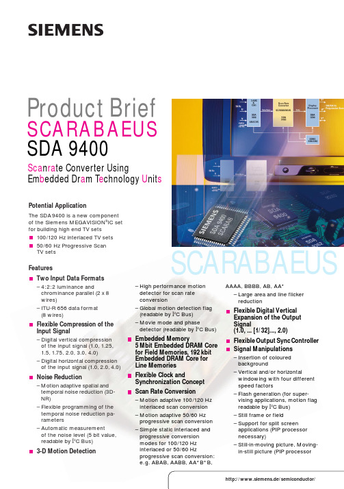
SCARABAEUSProduct BriefSCARABAEUS SDA 9400Sca n ra te Converter UsingEm b edded Dr a m T e chnology U nit sPotential ApplicationThe SDA9400 is a new component of the Siemens MEGAVISION ®IC set for building high end TV sets 100/120 Hz interlaced TV sets 50/60 Hz Progressive Scan TV sets FeaturesTwo Input Data Formats – 4:2:2 luminance andchrominance parallel (2x 8wires)– ITU-R 656 data format (8 wires)Flexible Compression of the Input Signal– Digital vertical compression of the input signal (1.0,1.25,1.5,1.75, 2.0, 3.0, 4.0)– Digital horizontal compression of the input signal (1.0,2.0,4.0)Noise Reduction– Motion adaptive spatial and temporal noise reduction (3D-NR)– Flexible programming of the temporal noise reduction pa-rameters– Automatic measurement of the noise level (5 bit value,readable by I 2C Bus)3-D Motion Detection– High performance motion detector for scan rate conversion– Global motion detection flag (readable by I 2C Bus)– Movie mode and phasedetector (readable by I 2C Bus)Embedded Memory5Mbit Embedded DRAM Core for Field Memories, 192kbit Embedded DRAM Core for Line MemoriesFlexible Clock andSynchronization Concept Scan Rate Conversion– Motion adaptive 100/120 Hz interlaced scan conversion – Motion adaptive 50/60 Hz progressive scan conversion – Simple static interlaced and progressive conversion modes for 100/120 Hz interlaced or 50/60 Hzprogressive scan conversion:e.g. ABAB, AABB, AA*B*B,AAAA, BBBB, AB, AA*– Large area and line flicker reduction Flexible Digital Vertical Expansion of the Output Signal(1.0, ... [1/32]..., 2.0)Flexible Output Sync Controller Signal Manipulations – Insertion of coloured background– Vertical and/or horizontalwindowing with four different speed factors– Flash generation (for super-vising applications, motion flag readable by I 2C Bus)– Still frame or field– Support for split screen applications (PIP processor necessary)– Still-in-moving picture, Moving-in-still picture (PIP processorshttp://www.siemens.de/semiconductor/Published by Semiconductor Group Siemens AktiengesellschaftOrdering No. B110-H7217-X-X-7600Printed in Germany PS 05983.1102980029SDA 9400 and a complete 1998. MassHow to reach us:http://www.siemens.de/semiconductor/address/address.htm© Siemens AG 1998.All Rights Reserved.Please note that any information contained in this publication may be subject to change. Siemens reserves the right to make changes to or to discontinue any product or service identified in this publication without notice.Please contact our regional offices to receive the latest version of the relevant information to verify,before placing orders, that the information being relied upon is current.(+43) 1-1707-35611(Melbourne),3121(+61) 3-94207111(+32) 2-5362348(+55) 11-836 2547(+1) 905-8198000(+41) 1-4953111(+49) 211-3991551(Hannover)(+49) 511-8772706(+49) 911-6547622(+49) 711-1373314(+49) 89-92214086(+45) 4477-4477Cantos-Madrid (+34)1-5148000 CEDEX 2(+33) 1-49223100(Helsinki)(+35) 9-51051RG 12 8FZ (+44) 1344-396000Amaroussio/Athen ట(+30) 1-6864111Hong Kongట(+852) 28320500Milanoట(+39) 2-6676-1 New Delhi 110014ట(+91)11-4617447Bangalore 560001ట(+91)80-2279874Mumbai 18ట(+91)22-4962199Dublin 4ట(+353) 1-6032348Tokyo 141-0022ట(+81) 3-544964Penangట(+60) 4-6449975Oslo 5ట(+47) 22-633000Den Haagట(+31) 70-3332429Aucklandట(+64) 9-5203033Amadoraట(+35) 1-4170011Islamabadట(+92) 51-212200Warszawaట(+48) 2-6709151Taipeiట(+886) 2-25237990Seoul 135-080ట(+82) 2-5277700Moskvaట(+7) 095-237-6476,-6911Kistaట(+46) 8-7033500Singapore 349253ట(+65) 8400610Findikli (Istanbul)ట(+90) 212-2510900Cupertino, CA 95014 ట(+1) 408-7774500Cupertino, CA 95014 ట(+1) 408-2577910Iselin, NJ 08830-2770ట(+1) 732-9064300Beijingట(+86) 10-685790-06,-07Shanghai 200003ట(+86) 21-63612618/19Halfway House 1685 ట(+27) 11-652-2000,-2700INDGR HKIIRLJNNLNZPPLRCROKRUSSSGPTRZAUSAVRC MALPKApplication Example。
9400技术规格对照

重量
□ M整机:约25公斤 (不可选,无油墨) □ M整机:约26公斤 (不可选,无油墨) □ 耗材盒:约0.8公斤(0.8升)
性能参数
打印
□ 任意介质,任意位置,灵活处理 □ 每条信息最多可包含4000字符 □ 1-5行信息 □ 高度1.2-10.7毫米(根据字型和喷头) □ 5/7/9/11/16/24/32点矩阵可选 □ 多字型可选 □ 可打印条形码、二维码等所有类型字符和符号
1
10.6
0.41
81
1000
•
•
•
•
•
•
•
•
•
•
•
•
•
•
•
•
•
•
•
•
•
•
•
•
•
•
•
•
•
•
•
•
•
•
•
•
•
•
•
•
•
•
•
•
1
6.1
0.67
132
316
•
•
•
•
1
6.9
0.60
118
318
•
•
•
•
1
9.2
0.47
92
324
•
•
•
•
1
7.8
0.57
112
155
1009
•
•
•
•
2
7.2
1.35
265
7/3
•
•
•
•
3
8
0.52
102
1006
•
9400TP 用户手册

版本 1.0 2002.09
2 Ecotech版权© 200 2002 所有权利被保留 本文件的信息如有更改,恕不另行通知,且文件中的信息不代表Ecotech Pty Ltd 的承诺。 在未经Ecotech同意,本手册中的任何部分均不允许再版、散布、传播或用于检 索系统保存,或者在没Ecotech Pty Ltd 同意之前简化电子版。 对本手册中可能出现的错误或者没有按照手册说明操作而引起的损害,Ecotech 厂家不承担任何责任。 Ecotech 承认本文档中涉及到的各种商标以及各厂家的专利商品名称及相关产 品,Ecotech 与手册中提及的任何厂家团体不存在附属关系,不赞成或支持 任何明确或暗示提及的意有所指的或已知的团体组织。 Ecotech 有权更改说明书中的部分或者全部内容,恕不另行通知。 每台Ecotech 9400TPIM 终端都有唯一的ID号码。 Ecotech证券代号:D-ECO-9400AD16-O. 澳大利亚印制 版本号:1.0 发行日期:2002.09 9400TP用户手册.Doc 手册ID:320
Ecotech Pty 081 12 Apollo Court Blackburn, Victoria 3130, AUSTRALIA 电话: 61 3 9894 2399 传真: 61 3 9894 2445 网址: .au 注意:本文是对英文版的9400TP终端连接手册的翻译,说明信息若有不同,请 以英文为准。
目录
1 引言 Introduction....................................................................................................................... 1 1.1 叙述
伦茨9400系列手册
!"#$ !"#$%& ! IP23 !"#$%&'() !" !F !"#
!"#$%&'()* !"#$%&'&()* !"#$%&'()* !"#$%&'()*+, !"#$%& ! IP54 UR CE ! MDFQA MDFQA !"# ! MDFQA ! ! MCS !" IP65
KTY !" CSA
OPC DriveServer
!"
!"#$
!"
!"#$%&'()*+,-./ !"# !"#$ !"#$%&(MMxxx) !"#$%&
!"#$%&'()*+,-. !"#$%&'()*+,-./0 !"#$%&' !"#$%& !"#$%&'() !"#$%& !"#$%&'
MM220
!"
7
!" !"#$%&'()*+ ,-
!"#$%&'()*+,
!"#"$
!"!#$% CAN ! Engineer !"#$%&'()
!"#$%&' !"# !"#$%&'()*+,-./01 !"#$ !"#$%& !"#$%&'()
伦茨9400中文使用手册
Notes:
注:
Diagnostic & parameter setting only
ready
Next Back
9400 Servo Drives
Target
First without engineer
Engineer with single drive, basics of TA Structured project, further TA FB editor Multi axis applications Online alternatives
Engineer with single drive, basics of TA Structured project, further TA FB editor Multi axis applications Online alternatives
Interfaces at the power module
ready
Next Back
5
LEDs
指示灯
CAN RUN
CAN 运行
OFF
= CAN inactive CAN没激活
= Pre-operational 预操作
= Operational 操作
DRIVE READY
驱动器投入
OFF
= Pulse inhibit due to an error 由于错误而禁止
9400 Servo Drives
Target
First without engineer Engineer with single drive, basics of TA Structured project, further TA FB editor Multi axis applications Online alternatives
伦茨9400伺服使用手册
伦茨9400伺服使用手册Welcome Practical introduction: 实用简介 L-force 9400 Servo DrivesL-force Engineer19 January 2007 Trainer: Torsten He Markus Toeberg Markus Warnecke StefanWitte 9400 Servo Drives Target Introduction to L-force 9400 and engineer First withoutengineer L-force 9400 和 engineer 的介绍 Engineer with single drive basics of TA 9400 servo drive set-up with interfaces Structured project further TA 9400伺服的接口设置 FB editor Parameter setting with Engineer and keypad Multi axis applications Onlinealternatives 通过Engineer 和操作面板进行参数设定 Technology Applications TA 技术应用 Diagnostics and configuration of the application with the function block editor使用功能块编辑器的应用配置和诊断 Next Back Multi axis application with horizontal CAN communication 2 使用CAN总线通讯的多轴应用 9400 Servo DrivesModular set-up ? 11 kW Target First without engineer Engineer with single drive basicsof TA Mounting base Structured project 安装底板 further TA FB editor Power module Multi axis applications 功率模块 Online alternatives Extension module 扩展模块Accessories Next Back 附件 3 9400 Servo Drives Interfaces at the power module Target First without engineer Engineer with single drive basics of TA CAN on board 内置CAN Structured project further TA 24 V supply and FB editor state bus 24V和状态总线 Multi axis applications Online alternatives Analog / digital IOs 2 module receptacles模拟/数字 I/O for extensions 2个扩展模块插槽 LEDs 指示灯 Diagnostic interfaceModule receptacle for 诊断接口 memory module 存储模块插槽 Resolver input 旋转变压器接口 Module receptacle for Next Multi encoder input safety technology Back 编码器接口安全模块插槽 HighLine StateLine: 1 个扩展插槽 4 9400 Servo DrivesLEDs Target First without engineer 指示灯 Engineer with single drive basics of TA CAN RUN CAN ERROR CAN 运行 Structured project CAN 错误further TA OFFCAN inactive CAN没激活 FB editor Bus warning Pre-operational 总线报警预操作 Multi axis applications Bus off Operational 总线关闭操作 Online alternativesDRIVE READY DRIVE ERROR 驱动器投入驱动器错误 OFF Pulse inhibit OFF OK due to an error 由于错误而禁止 Error status Controller inhibited 错误状态控制器禁止 System error Controller enabled 系统错误控制器使能 USER ready 24V 用户定义 Next Applicable in the application Back 在应用中使用 5 9400 ServoDrives Keypad Target First without engineer 面板 Engineer with single drive basics of TA 4 direction keys for navigation Structured project 4个方向键用于导航 further TA 2context-sensitive function keys FB editor 2个功能键 Multi axis applications Run and stop keys configurable Online alternatives 运行和停止键(可配置) Status field 状态区 Notes: 注: Diagnostic amp parameter setting only ready 仅用于诊断和参数设定Next Application is stored in the memory module Back 应用存储在存储模块中 6 9400Servo Drives Your training set-up… Target First without engineer 你的培训设置…Engineer with single drive basics of TA 2x 9400 HighLine Single Drive type 1(2个9400HighLine Structured project 单驱动型1) further TA – Extension module Ethernet (扩展模块-以太网) FB editor – Memory module MM330 (存储模块-MM330)Multiaxis applications – Safety module SM0 (安全模块-SM0) Online alternatives –Firmware version 01.51.01 (固件版本01.51.01) 2x Motor MCS06C41 with resolverand tooth wheel(2个伺服电机带旋变和齿型轮) – left Z 72 and 32 (左Z72,32)– right Z 60 and 20 (右Z60,20) Belt 皮带– left L 600 mm Z 120(左L600mm;Z120) Next – right L 535 mm Z 107 (右L535mm;Z107) Back Active application:“Actuator –speed“ (激活应用 Actuator 7 – speed) 9400 ServoDrives Exercise 1:Detect the drive status Target First without engineer by means of LEDs and keypad 通过指示灯和面板检测驱动器状态 Engineer with single drive basics of TA 1. Switch on the supply voltages 24 V and 400 V Structured project 电源上电further TA FB editor 2.Make the left drive rotate:运转左侧驱动器 Multi axis applicationsRFR Controllerenable Reglerfreigabe控制器使能 Online alternatives DI1 Deactivation of quick stop 快停取消 DI2 Start 启动 AI1 Speed setpoint 速度设定 3. Switch off the 400 Vsupply voltage 切断400V电源 4. Find out the drive status by means of the LEDs and the keypad 通过指示灯和面板观察状态 5. Make the logbook being displayed at the keypad Next 对面板显示进行记录 Back 8 9400 Servo Drives Start assistant 启动助手Target First without engineer Engineer with single drive basics of TA Structured projectfurther TA FB editor Multi axis applications Online alternatives Next Back 9 9400 Servo Drives User interface 用户界面 Target First without engineer Engineer with single drive basics of TA Work space Structured project 工作区 further TA Menu bar 菜单栏FB editor Tool bar Multi axis applications 工具栏 Onlinealternatives View bar 浏览栏Project tree 工程树 ready Next Back Messages and monitor panel 信息和监视盘 109400 Servo Drives Target First without engineer Going online 在线连接 Engineer withsingle drive basics of TA Diagnostic adapter 诊断适配器 Structured project further TACAN FB editor Ethernet TCP/IP 以太网 Multi axis applications Online alternatives Point-to-point- connection 点对点连接 ready Next 10-pole special cable Back RJ69 10芯RJ69电缆 11 9400 Servo Drives How to go online 如何连接 Target First withoutengineer Engineer with single drive basics of TA 1. Select the channel of communication 选择通讯通道 Structured project further TA FBeditor Multi axis applications 2. Start the search for devices 搜索驱动器 Online alternatives 3. Confirm the detected device 确认检测到的设备 4. Connect 连接 ready Next Back 12 9400 Servo Drives Colour represents online 在线的颜色表示 Target First without engineer Engineer with single drive basics of TA Value in the Structured project work space:工作区的颜色 further TAyellow modifiable FB editor Multi axis applications 黄可修改 Online alternativesgrey yellow read only 土黄只读 red communication error 红通讯错误NextBack 13 9400 Servo Drives Exercise 2: Detect the drive status Target First without engineer by means of the engineer 通过engineer检测驱动器状态 Engineer with singledrive basics of TA 1. Start the L-force Engineer. 启动 Structured project further TA 2.Create a new project by going online via diagnostic adapters and uploading the data fromthe right drive FB editor controller. Name the project “P ractical intro“. 创建一个新工Multi axis applications 程,并通过诊断电缆从右侧的驱动器上载数据,命名为”Practical Online alternatives intro” 3. Open the project tree. Click on the drive controller. Evaluate the drive status by means of the tab “Diagnostics”. 打开工程树,点击控制器,通过“Diagnostics”栏监控驱动器状态 4. Adapt the monitor window: Showthe “Device utilisation Ixt” as a log with a suitable resolution.观察设备利用率“Deviceutilisation Ixt”是否合适 Next 5. Save your project. 保存工程 Back 14 9400 ServoDrives Solution: Detect the drive status检测驱动器状态 Target First without engineerEngineer with single drive basics of TA Structured project further TA FB editor Multi axis applications Online alternatives Next Back 15 9400 Servo Drives Applications Target 应用 First without engineer Engineer with single drive basics of TA Application configured function of one device Structured project further TA 应用单个驱动器配置的功能 FB editor Multi axis applications How can applications be created如何建立应用, Online alternatives Two possible solutions:两个可能的方法: 1. Modify or extenda prefabricated technology application supplied by Lenze 修改和扩展伦茨预先提供的技术应用 2. Create the application completely by yourself insert “No Application” or just don’t insert any application. The empty application can be edited then within the function block editor 完全由用户自己创建(插入“No Application” 或不插入任何ready Next 应用,可以用功能块编辑器在空应用上编辑) Back 16 9400 Servo DrivesApplications supplied by Lenze…伦茨提供的应 Target First without engineer 用Engineer with single drive basics of TA are called technology applications e. g.我们称作“TA”,如: Structured project further TA – Actua.。
伦茨9400中文使用手册行业严选
7
Exercise 1: Detect the drive status
by means of LEDs and keypad 通过指示灯和面板检测驱动器状态
1.Switch on the supply voltages (24 V and 400 V)电
源上电
2.Make the left drive rotate:运转
Next Back
1
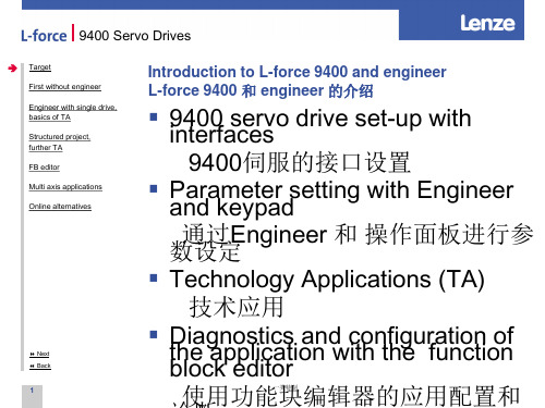
Introduction to L-force 9400 and engineer L-force 9400 和 engineer 的介绍
▪ 9in4te0r0fasceersvo drive set-up with 9400伺服的接口设置
▪ Panadrakmeeytpeardsetting with Engineer 数通设过定Engineer 和 操作面板进行参
Engineer with single drive,
basics of TA Structured project, further TA FB editor Multi axis applications Online alternatives
Start assistant 启动助手
Next Back
4.Find out the drive status by means of the LEDs and the keypad 通过指示灯和面板观察状态
5.Make the 一l类o特制gbook being
9400 Servo Drives
Target First without engineer
一类特制
9400 Servo Drives
Target First without engineer
霍尼韦尔 VersaFlow TWC 9400 产品说明书
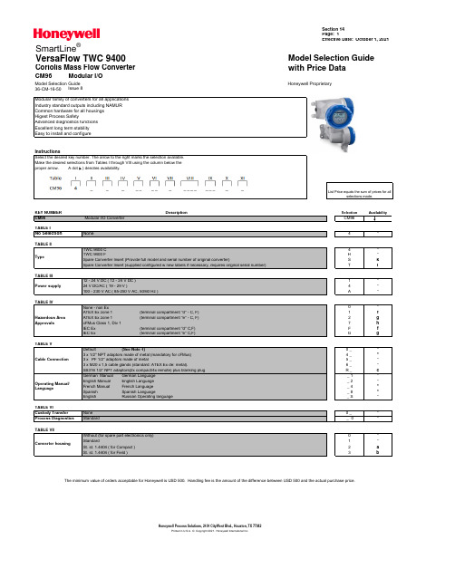
Section 14Page: 1Effective Date: October 1, 2021VersaFlow TWC 9400Model Selection Guide Coriolis Mass Flow Converterwith Price DataCM96Modular I/OModel Selection Guide Honeywell Proprietary36-CM-16-50 Issue 8The minimum value of orders acceptable for Honeywell is USD 500. Handling fee is the amount of the difference between USD 500 and the actual purchase price.Printed in U.S.A. © Copyright 2021. Honeywell International Inc.Honeywell Process Solutions, 2101 CityWest Blvd., Houston, TX 77042SmartLine ®Section 14Honeywell Proprietary Page: 2Effective Date: October 1, 2021Note 1: For cable gland option "0" - Default:For non Ex: 2x plastic M20 cable glands and 1 plastic blanking plugFor ATEX Ex d: 2 plastic transport plugs and 1 ATEX Ex d blanking plug made of metalFor ATEX Ex de: 2 metal M20 cable glands and 1 ATEX Ex d blanking plug made of metalThe minimum value of orders acceptable for Honeywell is USD 500. Handling fee is the amount of the difference between USD 500 and the actual purchase price.Honeywell Proprietary Section 14Page: 3Effective Date: October 1, 2021The minimum value of orders acceptable for Honeywell is USD 500. Handling fee is the amount of the difference between USD 500 and the actual purchase price.Section 14Honeywell Proprietary Page: 4Effective Date: October 1, 2021The minimum value of orders acceptable for Honeywell is USD 500. Handling fee is the amount of the difference between USD 500 and the actual purchase price.。
T9400S-软件说明书
机型确定 ☆
50.00Hz ★
0.00Hz ★
0.0%
★
0.00Hz ★
0.0%
★
0.00Hz ★
0.0%
★
0.0%
☆
64
☆
机型确定 ☆
1
★
4
★
9
★
12
★
0
★
43:PID 参数切换 46:速度控制/转矩控制切换 47:紧急停车 48:外部停车端子 2 50:本次运行时间清零 51: 泵 1 无效 52: 泵 2 无效 53: 泵 3 无效 54: 泵 4 无效
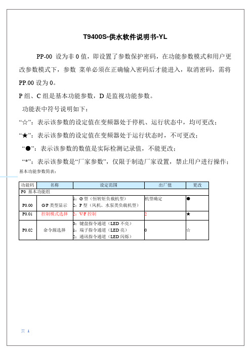
T9400S-供水软件说明书-YL
PP-00 设为非 0 值,即设置了参数保护密码,在功能参数模式和用户更 改参数模式下,参数 菜单必须在正确输入密码后才能进入,取消密码,需将 PP.00 设为 0。 P 组、C 组是基本功能参数,D 是监视功能参数。 功能表中符号说明如下: “☆”:表示该参数的设定值在变频器处于停机、运行状态中,均可更改; “★”:表示该参数的设定值在变频器处于运行状态时,不可更改; “●”:表示该参数的数值是实际检测记录值,不能更改; “*”:表示该参数是“厂家参数”,仅限于制造厂家设置,禁止用户进行操作;
启动频率
0.00Hz~10.00Hz
0.00Hz
☆
P6.04 启动频率保持时间
0.0s~100.0s
0.0s
★
P6.07
加减速方式
0:直线加减速
1:S 曲线加减速 A
0
★
P6.10
停机方式
0:减2:速S停曲车线加1:减自速由B停车
0
☆
P7 组 键盘与显示
页6
P7.01 Func 功能参数
GE OEC 9400 C-Arm产品说明书
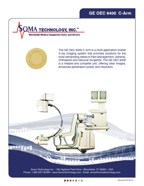
S ,★L R AO A R N T ★M T E O G Y IN★★Y ★★Soma Technology Inc. • 166 Highland Park Drive • Bloomfield, CT 06002 • USA Revised 9/07/2012X-Ray SystemSpecialty Packages Available • Clinical Platform• Expanded Surgical Platform• E xpanded Surgical Platform 4 Frames per second• Special Procedure Module• S pecial Procedure Module 4/30 FPSGenerator• 2.5 kHz High frequency• 6.0 kW Full-wave• Up to 120 kVp• U p to 100 mA for radiographic film exposures• F luoro boost mode up to 20 mA (optional)• Pulsed fluoro mode• P ulsed fluorography mode up to 60 mA (optional)• Full power from outlet:- 50 Hz or 60 Hz- 100V-15A to 240V-12AX-Ray Tube• Rotating anode X-ray tube• Focal spots: 0.3 mm and 0.1 mm • Anode heat capacity: 300,000 HU • Anode cooling rate: 70,000 HU/min • Housing heat capacity: 1,250,000 HUCollimator• Dual leaf collimation• Minimum beam size < 5 X 5 cm2• Leaves are continuously variable • R emotely controlled from the C-Arm control panelFluoroscopy Mode• Focal spot: 0.3 mm• kVp range: 40 – 120 kVp• mA range: 0.2 – 5.0 mA normal mode • m A range: Up to 20 mA boost mode (optional)• Auto, manual and pulsed modes • Continuous or One-Shot operation • ABS varies mA, kVp and camera gain • User specific ABS tables Pulsed Fluoroscopy Mode(opyional)• Focal spot: 0.3 mm• kVp range: 40 – 120 kVp• mA range: 0.2 – 5.0 mA• P ulse rate: 1, 2, 4, or 8 pulses persecond• Pulse width: 30 or 50 milliseconds• C omputer controlled ABS, mA, kVp andcamera gainPulsed Fluorography Mode(optional)• Focal spot: 0.3 mm• kVp range: 40 – 120 kVp• mA range: Up to 60 mA• P ulse rate: 1, 2, 4, or 8 pulses persecond• Pulse width: 35 or 50 millisecondsRadiographic Mode• Focal spot: 0.3 mm or 1.0 mm• Focal spot automatically selected• 0.3 mm - mAs range: 1 – 100 mAs• 1.0 mm - mAs range: 100 – 300 mAs• kVp range: 50 – 120 kVpVideo Imaging SystemImage Intensifier6 in Image Intensifier• Single-mode 6 in image intensifier- 6 in.: 1.4 lp/mm• DQE: 65% (typical)9 in Image Intensifier (optional)• T ri-mode 9 in / 6 in / 4.5 in imageintensifier- 9 in.: 2.3 lp/mm- 6 in.: 3.2 lp/mm- 4.5 in.: 3.8 lp/mm• DQE: 65% (typical)Video Camera• Vidicon Image Tube• 525 lines/frame• 360˚ motorized rotation• O n-screen orientation indicator (real-time feedback without fluoro)• Left-right image reversal• Top-bottom image reversal• 256 shades of grayVideo Monitors• D ual 17 in. Ultrabrite anti-glaremonitors• Ambient room light sensor• Remote brightness/contrast controlsHardcopy Options• Thermal printer• External DICOM box• Image Capture DeviceC-Arm Dimensions• Height: 66 in. / 83 in. (1681 / 2120 mm)• Width: 34 in. (864 mm)• Length: 74.5 in. (1892 mm)• Weight: 740 lbsWorkstation Dimensions• Height: 65 in. (1651 mm)• Width: 32 in. (813 mm)• Depth: 28 in (710 mm)• Weight: 360 lbs.Soma Technology Inc.166 Highland Park DriveBloomfield, CT 06002 • USA1.800.438.7662GE OEC 9400 C-ArmNote: The technical data given in this publication is for general information and is subject to change without notice. Actual configuration on the unit may vary. Contact our sales representatives for a complete list of details.。
OMEGA CN9300, CN9400, CN9500 和 CN9600 系列控制器产品说明书

Load
The relay output is allocated to SP1 and wired to switch the load (heater) using a contactor
Common Mode Rejection:
Specifications
Power: 100 to 240 Vac, ±10%, 50 to 60 Hz, 4 VA; optional 12 or 24 Vac/Vdc, ±20%, 50 to 60 Hz, 4 VA polarity is not required; the controllers are fitted with an internal 250 mA time lag fuse
CN9400/CN9600 Dual Display: Lower Display: 9 mm (0.35") orange LED output indicators-flashing SP1: Square green SP2: Round red SP3: 2nd round red (CN9600 only)
CN9600 Series Unique Features U Multi Ramp and Soak:
31 Programs, 126 Segments U Assured Soak U mA or V Linear Inputs U mA or V Linear Outputs U Three Outputs Standard U Analog Retransmission U High Accuracy ±0.1% Display of Linear Input
CN9300, CN9400, CN9500 Linear
- 1、下载文档前请自行甄别文档内容的完整性,平台不提供额外的编辑、内容补充、找答案等附加服务。
- 2、"仅部分预览"的文档,不可在线预览部分如存在完整性等问题,可反馈申请退款(可完整预览的文档不适用该条件!)。
- 3、如文档侵犯您的权益,请联系客服反馈,我们会尽快为您处理(人工客服工作时间:9:00-18:30)。
14-Pin
0°C to +70°C
SOIC (Narrow)
14-Pin
0°C to +70°C
Plastic DIP
14-Pin
– 40°C to +85°C
CerDIP 14-Pin
5 0°C to +70°C
Plastic DIP
14-Pin
– 40°C to +85°C
CerDIP
14-Pin
APPLICATIONS
s µP Data Acquisition s 13-Bit Analog-to-Digital Converters s Analog Data Transmission and Recording s Phase-Locked Loops s Frequency Meters/Tachometer s Motor Control s FM Demodulation
TC9401 ......................................................... 0.02% TC9400 ......................................................... 0.05% TC9402 ......................................................... 0.25% s Programmable Scale Factor
FUNCTIONAL BLOCK DIAGRAM
ORDERING INFORMATION
Part No.
Linearity (V/F) Package
4 Temperature Range
TC9400COD 0.05% TC9400CPD 0.05% TC9400EJD 0.05% TC9401CPD 0.01% TC9401EJD 0.01% TC9402CPD 0.25% TC9402EJD 0.25%
VOLTAGE-TO-FREQUENCY
Parameter
Definition
TC9401
TC9400
TC9402
Min Typ Max Min Typ Max Min Typ Max Unit
Accuracy Linearity 10 kHz
Linearity 100 kHz
Gain Temperature Drift (Note 1) Gain Variance401 TC9402
VOLTAGE-TO-FREQUENCY/FREQUENCY-TO-VOLTAGE CONVERTERS
FEATURES
GENERAL DESCRIPTION
2
Voltage-to-Frequency
s Choice of Guaranteed Linearity: TC9401 ......................................................... 0.01% TC9400 ......................................................... 0.05% TC9402 ......................................................... 0.25%
*Static-sensitive device. Unused devices must be stored in conductive material. Protect devices from static discharge and static fields. Stresses above those listed under Absolute Maximum Ratings may cause permanent damage to the device. These are stress ratings only and functional operation of the device at these or any other conditions above those indicated in the operational sections of the specifications is not implied. Exposure to Absolute Maximum Rating Conditions for extended periods may affect device reliability.
3 The devices can also be used as highly-accurate fre-
quency-to-voltage (F/V) converters, accepting virtually any input frequency waveform and providing a linearly-proportional voltage output.
IIN Overrange Response Time Digital Section VSAT @ IOL = 10mA VOUT Max – VOUT Common (Note 4) Pulse Frequency Output Width
Correction at Zero Adjust for Zero Output When Input is Zero Variation in Zero Offset Due to Temperature Change
Output Deviation From Straight Line Between Normalized Zero and Full-Scale Input
Output Deviation From Straight Line Between Normalized Zero Reading and Full-Scale Input
A complete V/F or F/V system only requires the addition of two capacitors, three resistors, and reference voltage.
Frequency-to-Voltage
s Operation ........................................... DC to 100 kHz s Choice of Guaranteed Linearity:
One Shot
÷2
Pulse Output Pulse/2 Output
7
IREF
Reference Voltage
TELCOM SEMICONDUCTOR, INC.
8
TC9400/1/2-5 11/6/96
3-287
元器件交易网
TC9400 TC9401 TC9402
Variation in Gain A Due to Temperature Change
Variation From Ideal Accuracy
Zero Offset (Note 2)
Zero Temperature Drift (Note 1) Analog Input IIN Full Scale
ELECTRICAL CHARACTERISTICS: VDD = +5V, VSS = – 5V, VGND = 0V, VREF = – 5V, RBIAS = 100kΩ,
Full Scale = 10kHz, unless otherwise specified. TA = +25°C, unless temperature range is specified (– 40°C to +85°C for E device, 0°C to +70°C for C device).
Full-Scale Analog Input Current to Achieve Specified Accuracy Overrange Current Settling Time to 0.1% Full Scale
0°C to +70°C
Plastic DIP
14-Pin CerDIP
– 40°C to +85°C
6
Integrator Capacitor
Input Voltage
RIN IIN
Reference Capacitor
Integrator OpAmp
Threshold Detector
TC9400
VOLTAGE-TO-FREQUENCY/ FREQUENCY-TO-VOLTAGE CONVERTERS
ABSOLUTE MAXIMUM RATINGS*
VDD – VSS ................................................................. +18V IIN ...........................................................................10mA VOUT Max –VOUT Common .......................................... 23V VREF – VSS ..............................................................– 1.5V Storage Temperature Range ................ – 65°C to +150°C Operating Temperature Range
s DC to 100 kHz (F/V) or 1Hz to 100kHz (V/F) s Low Power Dissipation .......................... 27mW Typ s Single/Dual Supply Operation .................................
