实验02-虚链路配置
7.配置OSPF虚链路

F0/2 172.17.1.2/24
172.16.1.1/24
RB
F0/0
Area 0
Area 0
F0/0
172.17.1.1/24
RC
RB能学习到 ,RC也能学习到 ,但是 和RC之间不能相互学习。 能学习到RA, 也能学习到 也能学习到RA,但是RB和 之间不能相互学习 之间不能相互学习。 能学习到
《网络设备》课程授课
计算机工程学院
李锋
RB和RC配置 和 配置 配置OSPF
RB(config)# router ospf 1 RB(config-router)# network 172.16.1.0 RC(config)# router ospf 1 RC(config-router)# network 172.17.1.0 0.0.0.255 0.0.0.255 aera 0 aera 0
F0/2 172.16.1.2/24
F0/3 F0/2 192.168.3.2/24 172.17.1./0
172.17.1.1/24 F0/0
RB
RC
Area 0
《网络设备》课程授课 计算机工程学院 李锋
配置OSPF虚链路( P71) 配置OSPF虚链路(实P71) 虚链路
192.168.1.1/24 F0/0 192.168.1.2/24 F0/1
Area 100
192.168.2.1/24 F0/1 192.168.2.2/24 F0/1
RID:192.168.100.29 :
SW1
X
F0/3 192.168.3.1/24
SW2
RID:192.168.100.33 :
SW1与SW2断开时,骨干区域 与 断开时, 被分割, 断开时 骨干区域Aera 0被分割,会产生非骨干区域连接两个骨干区域, 被分割 会产生非骨干区域连接两个骨干区域, 由于非骨干区域不能转发路由通告,导致RA和 路由学习不完整 路由学习不完整。 由于非骨干区域不能转发路由通告,导致 和RC路由学习不完整。 RA
OSPF虚链路(virtual-link)配置实例

OSPF虚链路(virtual-link)配置实例这个配置将验证一个OSPF虚电路(Virtual-Link)的过程,重点在观察虚链路连接的临时网络与正常区域间路由有何区别。
上图中区域4(area 4)没有和area 0直接相连。
在R2与R3之间配置了一条虚链路。
// R1 //int lo0ip ad 1.1.1.1 255.255.255.0int e0ip ad 192.1.1.1 255.255.255.0router os 1network 192.1.1.0 0.0.0.255 area 0// R2 //int lo0ip ad 2.2.2.2 255.255.255.0int e0ip ad 192.1.1.2 255.255.255.0int e1ip ad 193.1.1.2 255.255.255.0router os 1network 192.1.1.0 0.0.0.255 area 0network 193.1.1.0 0.0.0.255 area 1// R3 //int lo0ip ad 3.3.3.3 255.255.255.0int e1ip ad 193.1.1.3 255.255.255.0int e0ip ad 194.1.1.3 255.255.255.0router os 1network 193.1.1.0 0.0.0.255 area 1network 194.1.1.0 0.0.0.255 area 4// R4 //int lo0ip ad 4.4.4.4 255.255.255.0int e0ip ad 194.1.1.4 255.255.255.0router os 1network 194.1.1.0 0.0.0.255 area 4基本配置完成后,我们在每台路由器上分别来验证一下:r1#sh ip os neiTime Address Interface2.2.2.2 1 FULL/BDR 00:00:33 192.1.1.2 Eth ernet0/0r1#r1#sh ip ro1.0.0.0/24 is subnetted, 1 subnetsC 1.1.1.0 is directly connected, Loopback0O IA 193.1.1.0/24 [110/20] via 192.1.1.2, 00:00:19, Ethernet0/0C 192.1.1.0/24 is directly connected, Ethernet0/0//注意R1上有关于193.1.1.0的路由条目,是属于IA类型(域间路由)r2#sh ip os neiNeighbor ID Pri State DeadTime Address Interface1.1.1.1 1 FULL/DR 00:00:35 192.1.1.1 Eth ernet0/03.3.3.3 1 FULL/BDR 00:00:35 193.1.1.3 Eth ernet1/0r2#r2#r2#sh ip ro2.0.0.0/24 is subnetted, 1 subnetsC 2.2.2.0 is directly connected, Loopback0C 193.1.1.0/24 is directly connected, Ethernet1/0C 192.1.1.0/24 is directly connected, Ethernet0/0r3#sh ip os neiNeighbor ID Pri State DeadTime Address Interface2.2.2.2 1 FULL/DR 00:00:32 193.1.1.2 Eth ernet1/04.4.4.4 1 FULL/DR 00:00:34 194.1.1.4 Eth ernet0/0r3#sh ip ro3.0.0.0/24 is subnetted, 1 subnetsC 3.3.3.0 is directly connected, Loopback0C 193.1.1.0/24 is directly connected, Ethernet1/0O IA 192.1.1.0/24 [110/20] via 193.1.1.2, 00:02:49, Ethernet1/0C 194.1.1.0/24 is directly connected, Ethernet0/0//注意R3中有关于192.1.1.0的路由是属于IA类型(域间路由)r4#sh ip os neiTime Address Interface3.3.3.3 1 FULL/BDR 00:00:33 194.1.1.3 Eth ernet0/0r4#sh ip ro4.0.0.0/24 is subnetted, 1 subnetsC 4.4.4.0 is directly connected, Loopback0C 194.1.1.0/24 is directly connected, Ethernet0/0//R4上没有关于AREA 0内的任何路由信息我们下面在R2、R3上添加Virtual-link的配置:R2:router os 1area 1 virtual-link 3.3.3.3R3:router os 1area 1 virtual-link 2.2.2.2对比之前的路由信息,看有何区别:r1#sh ip ro1.0.0.0/24 is subnetted, 1 subnetsC 1.1.1.0 is directly connected, Loopback0O IA 193.1.1.0/24 [110/20] via 192.1.1.2, 00:00:01, Ethernet0/0C 192.1.1.0/24 is directly connected, Ethernet0/0O IA 194.1.1.0/24 [110/30] via 192.1.1.2, 00:00:01, Ethernet0/0//多了一条194网段的路由,类型IA(区域间)r2#sh ip ro2.0.0.0/24 is subnetted, 1 subnetsC 2.2.2.0 is directly connected, Loopback0C 193.1.1.0/24 is directly connected, Ethernet1/0C 192.1.1.0/24 is directly connected, Ethernet0/0O IA 194.1.1.0/24 [110/20] via 193.1.1.3, 00:00:06, Ethernet1/0//多了一条194网段路由,类型为IA(区域间)r3#sh ip ro3.0.0.0/24 is subnetted, 1 subnetsC 3.3.3.0 is directly connected, Loopback0C 193.1.1.0/24 is directly connected, Ethernet1/0O 192.1.1.0/24 [110/20] via 193.1.1.2, 00:02:56, Ethernet1/0C 194.1.1.0/24 is directly connected, Ethernet0/0//R3的192路由原本为IA类型(区域间),现在转为O类型(区域内),说明R3认为自已与192网段是直连的。
W3L300040 OSPF虚连接和验证配置 教师参考

实验5 OSPF虚连接和验证配置实验任务一:虚连接的配置步骤一:建立物理连接步骤二:IP地址配置步骤三:配置OSPF协议在RTA上启用OSPF协议,并在G0/0和Loopback0接口上使能OSPF,将它们加入OSPF 的Area0。
在RTB上启用OSPF协议,并在G0/0、G0/1和Loopback0接口上使能OSPF,将G0/0加入OSPF的Area0,将G0/1、Loopback0加入OSPF的Area1。
在RTC上启用OSPF协议,并在G0/0、G0/1和Loopback0接口上使能OSPF,将G0/1、Loopback0加入OSPF的Area1,将G0/0加入OSPF的Area2。
在RTD上启用OSPF协议,并在G0/0和Loopback0接口上使能OSPF,将它们加入OSPF的Area2。
请在下面填入配置RTA的命令:[RTA]ospf 1[RTA-ospf-1]area 0[RTA-ospf-1-area-0.0.0.0]network 1.1.1.1 0.0.0.0[RTA-ospf-1-area-0.0.0.0]network 10.0.0.0 0.0.0.255请在下面填入配置RTB的命令:[RTB]ospf 1[RTB-ospf-1]area 0[RTB-ospf-1-area-0.0.0.0]network 10.0.0.0 0.0.0.255[RTB-ospf-1-area-0.0.0.0]area 1[RTB-ospf-1-area-0.0.0.1]network 2.2.2.2 0.0.0.0[RTB-ospf-1-area-0.0.0.1]network 20.0.0.0 0.0.0.255请在下面填入配置RTC的命令:[RTC]ospf 1[RTC-ospf-1]area 1[RTC-ospf-1-area-0.0.0.1]network 3.3.3.3 0.0.0.0[RTC-ospf-1-area-0.0.0.1]network 20.0.0.0 0.0.0.255[RTC-ospf-1-area-0.0.0.1]area 2[RTC-ospf-1-area-0.0.0.2]network 30.0.0.0 0.0.0.255请在下面填入配置RTD的命令:[RTD]ospf 1[RTD-ospf-1]area 2[RTD-ospf-1-area-0.0.0.2]network 4.4.4.4 0.0.0.0[RTD-ospf-1-area-0.0.0.2]network 30.0.0.0 0.0.0.255配置结束后,在RTD上观察路由表,RTD的路由表中是否存在1.1.1.1/32这条路由?为什么?步骤四:_不存在。
OSPF虚链路--远离区域 0 的虚链路
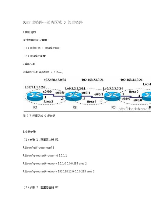
OSPF虚链路--远离区域 0 的虚链路1.实验目的通过本实验可以掌握:(1)远离区域0 虚链路的特征(2)虚链路的配置2.实验拓扑本实验的拓扑结构如图7-7 所示。
图7-7 远离区域0 虚链路3.实验步骤(1)步骤1:配置路由器R1R1(config)#router ospf 1R1(config-router)#router-id 1.1.1.1R1(config-router)#network 1.1.1.0 0.0.0.255 area 2R1(config-router)#network 192.168.12.0 0.0.0.255 area 2 (2)步骤2:配置路由器R2R2(config)#router ospf 1R2(config-router)#router-id 2.2.2.2R2(config-router)#network 2.2.2.0 0.0.0.255 area 1R2(config-router)#network 192.168.12.0 0.0.0.255 area 2 R2(config-router)#network 192.168.23.0 0.0.0.255 area 1 R2(config-router)#area 1 virtual-link 3.3.3.3(3)步骤3:配置路由器R3R3(config)#router ospf 1R3(config-router)#router-id 3.3.3.3R3(config-router)#network 3.3.3.0 0.0.0.255 area 0R3(config-router)#network 192.168.23.0 0.0.0.255 area 1 R3(config-router)#network 192.168.34.0 0.0.0.255 area 0 R3(config-router)#area 1 virtual-link 2.2.2.2(4)步骤4:配置路由器R4R4(config)#router ospf 1R4(config-router)#router-id 4.4.4.4R4(config-router)#network 4.4.4.0 0.0.0.255 area 0R4(config-router)#network 192.168.34.0 0.0.0.255 area 04.实验调试在路由器R4 上查看路由表:R4#show ip routeCodes: C –connected, S –static, R –RIP, M –mobile, B –BGPD –EIGRP, EX –EIGRP external, O –OSPF, IA –OSPF inter areaN1 –OSPF NSSA external type 1, N2 –OSPF NSSA external type 2 E1 –OSPF external type 1, E2 –OSPF external type 2i –IS-IS, L1 –IS-IS level-1, L2 –IS-IS level-2, ia –IS-IS inter area * –candidate default, U –per-user static route, o –ODRP –periodic downloaded static routeGateway of last resort is not setO IA 192.168.12.0/24 [110/192] via 192.168.34.3, 00:02:19, Serial0/0/0 1.0.0.0/32 is subnetted, 1 subnetsO IA 1.1.1.1 [110/193] via 192.168.34.3, 00:02:19, Serial0/0/02.0.0.0/32 is subnetted, 1 subnetsO IA 2.2.2.2 [110/129] via 192.168.34.3, 00:02:19, Serial0/0/03.0.0.0/32 is subnetted, 1 subnetsO 3.3.3.3 [110/65] via 192.168.34.3, 00:02:19, Serial0/0/04.0.0.0/24 is subnetted, 1 subnetsC 4.4.4.0 is directly connected, Loopback0O IA 192.168.23.0/24 [110/128] via 192.168.34.3, 00:02:19, Serial0/0/0 C 192.168.34.0/24 is directly connected, Serial0/0/0从R4 的路由表的输出,可以看出路由器R1 能够通过使用转接区域1 的虚拟链路到达区域0。
OSPF虚链路实验研究

OSPF虚链路实验研究一.实验目的理解OSPF虚链路原理及何时需要使用虚链路掌握OSPF虚链路配置方法(1)使用虚链路将区域连接到骨干区域的配置方法;(2)使用虚链路将不连续的区域0连接起来的配置方法二、实验拓扑图使用虚链路将区域连接到骨干区域的拓扑图使用虚链路将不连续的区域0连接起来的拓扑图三、实验步骤及要求(一)使用虚链路将区域连接到骨干区域1.R2、R3、R4配置OSPFR2(config)#router ospf 1R2(config-router)#network 172.16.255.4 0.0.0.3 area 2R2(config-router)#exitR2的f0/1接口先不要宣称networkR3(config)#router ospf 1R3(config-router)#network 172.16.255.4 0.0.0.3 area 2R3(config-router)#network 172.16.255.8 0.0.0.3 area 0R4(config)#router ospf 1R4(config-router)#network 172.16.255.8 0.0.0.3 area 0R4(config-router)#network 172.16.16.0 0.0.0.255 area 12.查看R2的路由表R2#show ip route172.16.0.0/16 is variably subnetted, 4 subnets, 2 masksC 172.16.255.0/30 is directly connected, FastEthernet0/1C 172.16.255.4/30 is directly connected, FastEthernet0/0O IA 172.16.255.8/30 [110/2] via 172.16.255.6, 00:06:42, FastEthernet0/0O IA 172.16.16.1/32 [110/3] via 172.16.255.6, 00:06:09, FastEthernet0/03.再次配置R1和R2的OSPF协议R1(config)#router ospf 1R1(config-router)#network 172.16.255.0 0.0.0.3 area 3R1(config-router)#network 172.16.1.0 0.0.0.255 area 3R1(config-router)#exitR2(config)#router ospf 1R2(config-router)#network 172.16.255.0 0.0.0.3 area 3R2(config-router)#exit4. 查看R1与R2的OSPF的邻居表R1#show ip ospf neighborNeighbor ID Pri State Dead Time Address Interface 172.16.255.5 1 FULL/BDR 00:00:39 172.16.255.2 FastEthernet0/0 R2#show ip ospf neighborNeighbor ID Pri State Dead Time Address Interface 172.16.255.9 1 FULL/BDR 00:00:36 172.16.255.6 FastEthernet0/0 172.16.1.1 1 FULL/DR 00:00:30 172.16.255.1 FastEthernet0/1 5. 查看R1的路由表R1#show ip route172.16.0.0/16 is variably subnetted, 2 subnets, 2 masksC 172.16.255.0/30 is directly connected, FastEthernet0/0C 172.16.1.0/24 is directly connected, Loopback0通过观察R1的路由表,R1的路由器无法学习到骨干区域、area 1和area 2区域的路由。
ospf的虚拟链路

192.168.3.2/24
E0
192.168.4.1/24
R5(QuidwayAR-28)
E0/0
192.168.4.2/24
Loopback 1
192.168.5.1/24
案列实施:
1)、配置IP地址与ospf区域
R2配置:
sysname R2
router id 2.2.2.2
local-user admin
R3配置:
ospf
area 0.0.0.2
network 192.168.3.1 0.0.0.0
vlink-peer 4.4.4.4#指定对端的router id,这个对端指的是连接下一个区域的路由器
R4配置:
ospf enable
vlink peer-id 3.3.3.3 transit-area 0.0.0.2#指定对端的router id
password cipher %K/T]3SXOF$[FR9&2:*aF1!!
service-type telnet level 3
vlan 20
vlan 30
#
interface Vlan-interface20
ip address 192.168.2.1 255.255.255.0
#
interface LoopBack1
ip address 192.168.1.1 255.255.255.0
ospf
area 0.0.0.0
network 192.168.1.1 0.0.0.0
network 192.168.2.1 0.0.0.0
R3配置:
sysname R3
router id 3.3.3.3
虚链路(Virtual Link)
4.1.5 虚链路(Virtual Link)以下两种情况需要使用到虚链路:1. 通过一个非骨干区域连接到一个骨干区域。
2. 通过一个非骨干区域连接一个分段的骨干区域两边的部分区域。
虚链接是一个逻辑的隧道(Tunnel),配置虚链接的一些规则:1. 虚链接必须配置在2个ABR之间。
2. 虚链接所经过的区域叫Transit Area,它必须拥有完整的路由信息。
3. Transit Area不能是Stub Area。
4. 尽可能的避免使用虚链接,它增加了网络的复杂程度和加大了排错的难度。
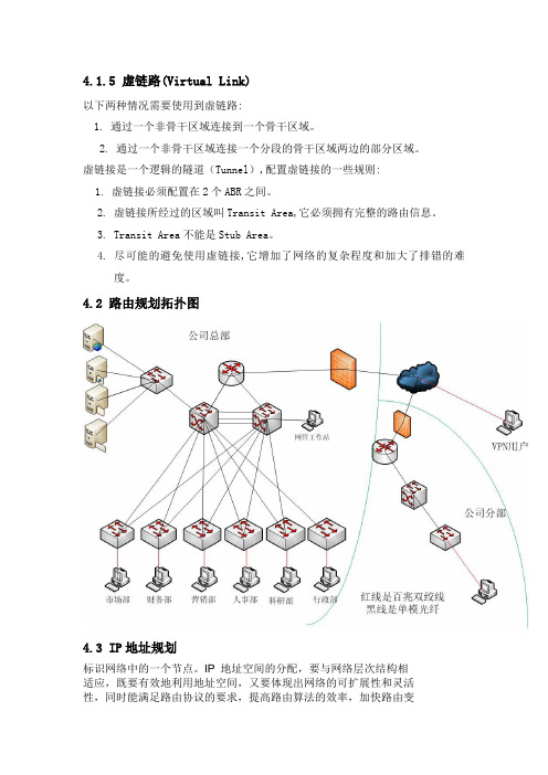
4.2路由规划拓扑图4.3 IP地址规划标识网络中的一个节点。
IP 地址空间的分配,要与网络层次结构相适应,既要有效地利用地址空间,又要体现出网络的可扩展性和灵活性,同时能满足路由协议的要求,提高路由算法的效率,加快路由变化的收敛速度。
我们根据以下几个原则来分配IP 地址:唯一性:一个IP 网络中不能有两个主机采用相同的IP 地址简单性:地址分配应简单易于管理,降低网络扩展的复杂性,简化路由表的款项连续性:连续地址在层次结构网络中易于进行路由总结(RouteSummarization),大大缩减路由表,提高路由算法的效率可扩展性:地址分配在每一层次上都要留有余量,在网络规模扩展时能保证地址总结所需的连续性灵活性:地址分配应具有灵活性,可借助可变长子网掩码技术(VLSM Variable-Length Subnet Mask),以满足多种路由策略的优化,充分利用地址空间。
部门网段子网掩码网关地址广播地址VLAN总部市场部10.1.1.0 255.255.255.0 10.1.1.1 10.1.1.255 2 财务部10.1.2.0 255.255.255.0 10.1.2.1 10.1.2.255 3 营销部10.1.3.0 255.255.255.0 10.1.3.1 10.1.3.255 4 人事部10.1.4.0 255.255.255.0 10.1.4.1 10.1.4.255 5 科研部10.1.5.0 255.255.255.0 10.1.5.1 10.1.5.255 6 行政部10.1.6.0 255.255.255.0 10.1.6.1 10.1.6.255 7部门网段子网掩码子网网段网关地址广播地址保留地址VLAN市场部10.10.0.0 255.255.255.224 10.10.0.0/27 10.10.0.1 10.10.0.31 6个 2 财务部10.10.0.0 255.255.255.248 10.10.0.96/29 10.10.0.97 10.10.0.103 1个 3营销部10.10.0.0 255.255.255.224 10.10.0.32/27 10.10.0.33 10.10.0.63 10个 4 分部人事部10.10.0.0 255.255.255.240 10.10.0.64/28 10.10.0.65 10.10.0.79 4个 5 科研部10.10.0.0 255.255.255.240 10.10.0.80/28 10.10.0.81 10.10.0.95 4个 6 行政部10.10.0.0 255.255.255.248 10.10.0.104/29 10.10.0.105 10.10.0.111 1个7第五章网络安全解决方案5.1 网络边界安全威胁分析与非安全网络的互联面临的安全问题与网络内部的安全是不同的,主要的原因是攻击人是不可控的,攻击是不可溯源的,也没有办法去“封杀”,一般来说网络边界上的安全问题主要有下面几个方面:1、信息泄密:网络上的资源是可以共享的,但没有授权的人得到了他不该得到的资源,信息就泄露了。
实验5 OSPF虚链路配置

(一)实验内容
1、实现功能如下
实现不能与骨干网络直连的ospf区域与骨干网络交互信息。
R2(config-router)#area 1 virtual-link 192.168.34.3!配置虚链路穿越area 1
R3(config-router)#area 1 virtual-link 192.168.23.2!配置虚链路穿越area 1
2、实验拓扑图:
(二)实验步骤
第一步:在主机的运行中分别对这四个路由器进行基本配置及ospf协议配置
(1)Router 1的配置
R1(config)#int s0/0
R1(config)#encap ppp
R1(config-if)#ip add 192.168.12.1 255.255.255.0
R1(config-if)#clock rate 64000
R1(config-if)#no shut
R1(config-if)#exit
R1(config)#int e1/0
R1(config)#ip add 192.16 shut
R1(config)#exit
R1(config)#router ospf 100
R1(config-router)#network 192.168.12.0 0.0.0.255 area 0
R1(config-router)#network 192.168.11.0 0.0.0.255 area 0
《OSPF虚链路配置》实验报告
2014至2015学年第1学期
姓名
系别
计科系
实验地点
综合楼四楼实验室
学号
年级、班
12级计科2班
6、OSPF虚链路的原理和配置

OSPF虚链路的原理和配置一、原理概述通常情况下,一个OSPF网路的每个非骨干区域都必须与骨干区域通过ABR路由器直接连接,非骨干区域之间的通信都需要通过骨干区域进行中转。
但是在现实中,可能会因为各种限制条件,导致非骨干区域和骨干区域无法相连接,在这种情况下,可以使用OSPF虚链路(Virtual Link)来实现非骨干区域和骨干区域在逻辑上的直接相连。
OSPF协议还要求骨干区域是必须唯一且连续,然而,由于发生故障等原因,骨干区域可能出现被分割的情况。
此时,同样可以使用虚链路来实现物理上被分割的骨干区域能够逻辑上相连。
虚链路在网络中会穿越其他区域,因此可能会带来安全隐患,所以通常都会对虚链路进行认证功能的配置。
虚链路认证其实是OSPF接口认证的一种,支持MD5、HMAC-MD5、明文以及Keychain等特性。
二、案例实验实验拓扑图1所示,实验编址如表1所示。
本实验模拟一个企业网络场景,全网运行OSPF,路由器R1、R2为公司总部路由器,R3是新建公司的接入路由器,R4为分公司下面的分支机构的接入路由器。
由于网络升级尚未完成,所以目前的区域划分是:R1与R2之间链路位于区域0,R3与R1、R3与R2之间的链路位于区域1,R3与R4之间的链路位于区域2.网络需求:使用虚链路技术,使得分支机构所属的区域2可以访问总部网络,且优先使用路径R4→R3→R1,并且R4→R3→R2路径作为备份。
同时总部路由器R1和R2之间的通信需要采用R1→R3→R2路径作为冗余备份。
另外为了网络安全,对于使用的虚链路进行认证功能的配置。
实验拓扑图1关于网络拓扑基本配置和OSPF网络的搭建,这里就不在详细叙述了,我们从虚链路的搭建开始介绍。
1、使用虚链路使区域2和区域0建立逻辑链接配置虚链路使得区域2和区域0在逻辑上相互连接,此时区域1将作为区域2和区域0之间的传输区域。
虚链路配置操作将在连接区域2和区域1的R3上,及连接区域0和区域1的ABR的路由器R1上。
OSPF虚链路
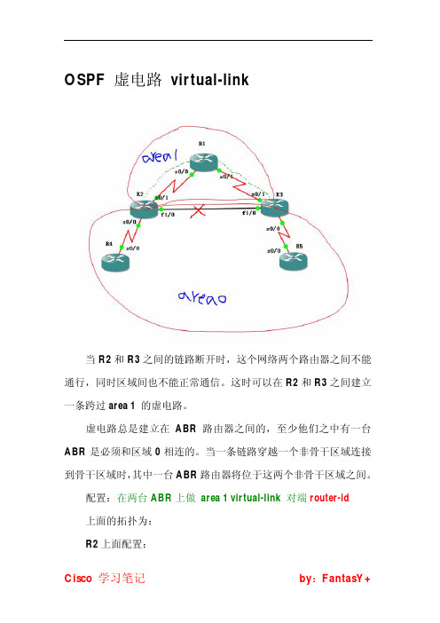
当 R2 和 R3 之间的链路断开时,这个网络两个路由器之间不能 通行,同时区域间也不能正常通信。这时可以在 R2 和 R3 之间建立 一条跨过 area 1 的虚电路。 虚电路总是建立在 ABR 路由器之间的,至少他们之中有一台 ABR 是必须和区域 0 相连的。当一条链路穿越一个非骨干区域连接 到骨干区域时, 其中一台 ABR 路由器将位于这两个非骨干区域之间。 配置:在两台 ABR 上做 area 1 virtual-link 对端 router-id 上面的拓扑为: R2 上面配置:
Cisco 学习笔nfig-router)#area 1 virtual-link 3.3.3.3 R3 上面配置: R3(config-router)#area 1 virtual-link 2.2.2.2
Cisco 学习笔记
by:FantasY+
思科CCNP认证OSPF之认证、虚链路及过滤案例分析
思科CCNP认证OSPF之认证、虚链路及过滤案例分析本⽂讲述了思科CCNP认证OSPF之认证、虚链路及过滤。
分享给⼤家供⼤家参考,具体如下:认证1:链路认证 //防⽌链路接⼊⾮法路由器(⽆授权),在链路的所有设备都需要开启1> 明⽂认证 //不安全在IOS15.2的版本中的配置:int e0/0 //进⼊需要做认证的接⼝ip ospf authentication //开启明⽂认证ip ospf authentication key-chain k //k为key-chain的名字,⾃⾏决定key chain kkey 1key-string cisco //输⼊明⽂认证的密钥在IOS15.4版本中的配置:int e0/0 //进⼊需要认证的接⼝ip ospf authentication //开启明⽂认证ip ospf authentication-key cisco //(密钥,可不写)将密钥进⾏⽐对,若⽐对成功则认证成功。
PS:开启明⽂认证后,本地的hello包中认证类型的字段发⽣变化。
未认证时为0,开启认证后将0置位为1。
做认证的邻居间必须保持⼀致。
若仅链路的⼀端开启认证,则整条链路的路由不互通。
同时明⽂认证若仅开启认证,不输⼊密钥,则丧失了认证的安全性,容易被他⼈窃取数据。
2> md5认证 //安全int e0/0 //进⼊需要做md5认证的接⼝ip ospf authentication message-digest //开启认证ip ospf authentication message-digest-key 1 md5 cisco //输⼊密钥PS:与明⽂认证⼀样,邻居间的md5认证密钥必须保持⼀致,否则不能进⾏通信。
2:区域认证 //防⽌区域接⼊⾮法路由器,区域内所有设备都需要开启1> 明⽂认证router ospf 1area 0 authenticationint e0/0ip ospf authentication-key cisco //接⼝写⼊认证密钥2> md5认证router ospf 1area 0 authentication message-digest //区域0开启md5认证int e0/0ip ospf message-digest-key 1 md5 cisco //接⼝写⼊md5认证密钥PS:在路由器上开启关于某个区域的明⽂或密⽂认证,实际上是将该路由上⼯作与此区域的接⼝修改认证类型字段为明⽂或密⽂,密钥需要在各个接⼝逐⼀配置。
H3Cospf实验和ospf虚链路

H3Cospf实验和ospf虚链路RT1配置<RT1>dis cu[V200R003C00]#sysname RT1#snmp-agent local-engineid 800007DB03000000000000snmp-agent#clock timezone Indian Standard Time minus 05:13:20clock daylight-saving-time Day Light Saving Time repeating 12:32 9-1 12:32 11-23 00:00 2005 2005#drop illegal-mac alarm#set cpu-usage threshold 80 restore 75#aaaauthentication-scheme defaultauthorization-scheme defaultaccounting-scheme defaultdomain defaultdomain default_adminlocal-user admin password cipher %$%$K8m.Nt84DZ}e#<0`8bmE3Uw}%$%$ local-user admin service-type http#firewall zone Localpriority 15#interface Ethernet0/0/0#interface Ethernet0/0/1#interface Ethernet0/0/2#interface Ethernet0/0/3#interface Ethernet0/0/4#interface Ethernet0/0/5#interface Ethernet0/0/6#interface Ethernet0/0/7#interface GigabitEthernet0/0/0ip address 172.16.1.1 255.255.255.252 #interface GigabitEthernet0/0/1#interface NULL0#interface LoopBack0ip address 192.168.0.1 255.255.255.0 #ospf 1import-route directarea 0.0.0.0network 172.16.1.0 0.0.0.3#user-interface con 0authentication-mode passworduser-interface vty 0 4user-interface vty 16 20#wlan ac#ReturnRT2配置[RT2]dis cu[V200R003C00]#sysname RT2#snmp-agent local-engineid 800007DB03000000000000snmp-agent#clock timezone Indian Standard Time minus 05:13:20clock daylight-saving-time Day Light Saving Time repeating 12:32 9-1 12:32 11-23 00:00 2005 2005#drop illegal-mac alarm#set cpu-usage threshold 80 restore 75#aaaauthentication-scheme defaultauthorization-scheme defaultaccounting-scheme defaultdomain defaultdomain default_adminlocal-user admin password cipher %$%$K8m.Nt84DZ}e#<0`8bmE3Uw}%$%$ local-user admin service-type http#firewall zone Localpriority 15#interface Ethernet0/0/0#interface Ethernet0/0/1#interface Ethernet0/0/2#interface Ethernet0/0/3#interface Ethernet0/0/4#interface Ethernet0/0/5#interface Ethernet0/0/6#interface Ethernet0/0/7interface GigabitEthernet0/0/0ip address 172.16.1.2 255.255.255.252#interface GigabitEthernet0/0/1ip address 172.16.1.5 255.255.255.252#interface NULL0#interface LoopBack1ip address 192.168.1.1 255.255.255.0#ospf 1import-route directarea 0.0.0.0network 172.16.1.0 0.0.0.3area 0.0.0.1network 172.16.1.0 0.0.0.255vlink-peer 172.16.1.6#user-interface con 0authentication-mode passworduser-interface vty 0 4user-interface vty 16 20#wlan ac#returnRT3 配置<RT3>dis cu[V200R003C00]#sysname RT3#snmp-agent local-engineid 800007DB03000000000000snmp-agent#clock timezone Indian Standard Time minus 05:13:20clock daylight-saving-time Day Light Saving Time repeating 12:32 9-1 12:32 11-23 00:00 2005 2005#drop illegal-mac alarm#set cpu-usage threshold 80 restore 75aaaauthentication-scheme defaultauthorization-scheme defaultaccounting-scheme defaultdomain defaultdomain default_adminlocal-user admin password cipher %$%$K8m.Nt84DZ}e#<0`8bmE3Uw}%$%$ local-user admin service-type http#ospfv3 1#firewall zone Localpriority 15#interface Ethernet0/0/0#interface Ethernet0/0/1#interface Ethernet0/0/2#interface Ethernet0/0/3#interface Ethernet0/0/4#interface Ethernet0/0/5#interface Ethernet0/0/6#interface Ethernet0/0/7#interface GigabitEthernet0/0/0ip address 172.16.1.6 255.255.255.252#interface GigabitEthernet0/0/1ip address 172.16.1.9 255.255.255.252#interface NULL0#interface LoopBack2ip address 192.168.2.1 255.255.255.0#ospf 1area 0.0.0.1network 172.16.1.4 0.0.0.3vlink-peer 172.16.1.2area 0.0.0.2network 172.16.1.8 0.0.0.3vlink-peer 172.16.1.2#user-interface con 0authentication-mode passworduser-interface vty 0 4user-interface vty 16 20#wlan ac#returnRT4配置[RT4]dis cu[V200R003C00]#sysname RT4#snmp-agent local-engineid 800007DB03000000000000snmp-agent#clock timezone Indian Standard Time minus 05:13:20clock daylight-saving-time Day Light Saving Time repeating 12:32 9-1 12:32 11-23 00:00 2005 2005#drop illegal-mac alarm#set cpu-usage threshold 80 restore 75#aaaauthentication-scheme defaultauthorization-scheme defaultaccounting-scheme defaultdomain defaultdomain default_adminlocal-user admin password cipher %$%$K8m.Nt84DZ}e#<0`8bmE3Uw}%$%$ local-user admin service-type http#firewall zone Localpriority 15#interface Ethernet0/0/0#interface Ethernet0/0/1#interface Ethernet0/0/2#interface Ethernet0/0/3#interface Ethernet0/0/4#interface Ethernet0/0/5#interface Ethernet0/0/6#interface Ethernet0/0/7#interface GigabitEthernet0/0/0ip address 172.16.1.10 255.255.255.252 #interface GigabitEthernet0/0/1#interface NULL#ospf 1area 0.0.0.2network 172.16.1.8 0.0.0.3#user-interface con 0authentication-mode passworduser-interface vty 0 4user-interface vty 16 20#wlan ac#return。
虚链路技术

Virtual-link虚链路技术
一、虚链路的介绍
1、使用虚链路可以使非骨干区域之间进行通信
2、可以扩展ABR、但虚拟路径不产生数据
3、虚链路的存在只是暂时的
4、只能在OSPF路由协议中使用
二、虚链路的配置命令
1、OSPF中配置虚链路
①router ospf 100 :进入OSPF进程
②area 1 virtual-link (对方id) :指定对方Route-id生成虚链路
2、虚链路的明文验证命令
①router ospf 100 :进入OSPF进程
②area 1 virtual-link (对方id) authentication :开启明文验证
③area 1 virtual-link (对方id) authentication-key (名字) :为虚链路验证起名字
3、虚链路的密文验证命令
①router ospf 100 :进入OSPF进程
②area 1 virtual-link (对方id) authentication message-digest :开启密文验证
③area 1 virtual-link (对方id) authentication message-digest-key 1 md5 (名字) :为密文虚链路起名字
4、查看虚链路配置
①show running-config |section router ospf :查看OSPF里虚链路配置。
ospf虚链路(点到多点)
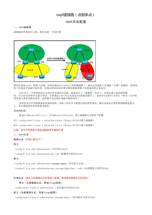
ospf虚链路(点到多点)OSPF其他配置一、OSPF虚链路虚链路的作用是什么呢,我们先看一个拓扑图黄色区域是area0,即骨干区域,如果如图示RT1与RT6之间的链路断了,那么会出现骨干区域被“分裂”的情况,很明显骨干区域是不能被分割开的,出现这种状况的时候可能会影响到整个自制系统的正常运行。
OSPF这么一个优秀的协议当然会有处理的办法啦,那就是引入“虚链路”技术了。
如果出现上面这样的情况,RT1与RT6仍然可以建立邻居,只要理论上RT1可以有到达RT6的路径就行了,此时RT5会替RT1与RT6 “转交”OSPF的邻居建立消息及路由信息,这样就不会出现区域被分割的状况了。
这种技术只作为特殊事故处理而用的,实际工程中并不期望出现这样的情况,最好还是有正常的物理链路连接为上,所以规划拓扑的时候要考虑好。
虚链路配置:假设RT1的route-id为 1.1.1.1, RT6的route-id为 6.6.6.6,那么虚链路可以做如下配置:RT1(config-router)# area 1 virtual-link 6.6.6.6(在area 1内与RT6建立虚链路)RT6(config-router)# area 1 virtual-link 1.1.1.1(在area 1内与RT1建立虚链路)注意:命令中所指的区域是虚链路要穿越的区域二、OSPF认证链路认证(在接口模式下)明文(config-if)# ip ospf authentication(开启明文认证)(config-if)# ip ospf authentication-key 123(配置明文密码为123)密文(config-if)# ip ospf authentication message-digest(开启密文认证)(config-if)# ip ospf authentication-key message-digest-key 1 md5 123(配置密文密码为123)区域认证(要在已有链路认证的基础上配置,密码就是链路认证的密码)明文(先做链路认证,再进入ospf进程)(config-route)# area 0 authentication (对区域0开启明文认证)密文(先做链路认证,再进入ospf进程)(config-route)# area 0 authentication message-digest(对区域0开启密文认证)虚链路认证:只要在配置虚链路时后面加上链路认证的方式就可以了,如下:虚链路明文认证:(config-route)# area 1 virtual-link 6.6.6.6 authentication(开启虚链路明文认证)(config-route)# area 1 virtual-link 6.6.6.6 authentication key 123(配置明文密码为123)密文的就不写了,套上面的认证的格式,改几个关键字就行了。
CCNP路由实验OSPF虚链路的配置
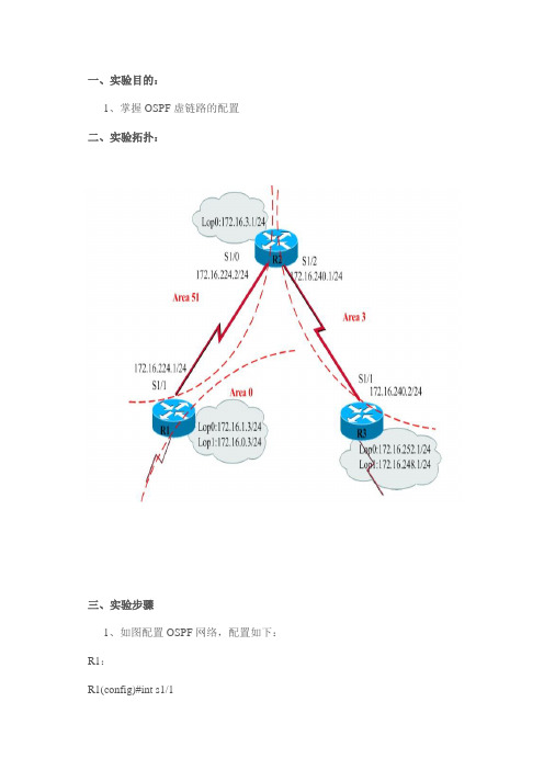
一、实验目的:1、掌握OSPF虚链路的配置二、实验拓扑:三、实验步骤1、如图配置OSPF网络,配置如下:R1:R1(config)#int s1/1R1(config-if)#ip add 172.16.224.1 255.255.255.0R1(config-if)#no shutR1(config)#int loop 0R1(config-if)#ip add 172.16.1.3 255.255.255.0R1(config)#int loop 1R1(config-if)#ip add 172.16.0.3 255.255.255.0R1(config-if)#exitR1(config)#router ospf 1R1(config-router)#network 172.16.224.0 0.0.0.255 area 51 R1(config-router)#network 172.16.0.0 0.0.0.255 area 0R1(config-router)#network 172.16.1.0 0.0.0.255 area 0R1(config-router)#R2:R2(config)#int s1/0R2(config-if)#ip add 172.16.224.2 255.255.255.0R2(config-if)#no shutR2(config)#int s1/2R2(config-if)#ip add 172.16.240.1 255.255.255.0R2(config-if)#no shutR2(config)#int loop 0R2(config-if)#ip add 172.16.3.1 255.255.255.0R2(config-if)#exitR2(config)#router ospf 1R2(config-router)#network 172.16.224.0 0.0.0.255 area 51R2(config-router)#network 172.16.3.0 0.0.0.255 area 51R2(config-router)#network 172.16.240.0 0.0.0.255 area 3R3:R3(config)#int s1/1R3(config-if)#ip add 172.16.240.2 255.255.255.0R3(config-if)#no shutR3(config)#int loop 0R3(config-if)#ip add 172.16.252.1 255.255.255.0R3(config)#int loop 1R3(config-if)#ip add 172.16.248.1 255.255.255.0R3(config)#router ospf 1R3(config-router)#network 172.16.240.0 0.0.0.255 area 32、使用show ip route、show ip ospf nei查看OSPF配置结果。
OSPF的虚链路配置实例
OSPF的虚链路配置实例虚连接:Virtual Link为了避免区域间的环路,OSPF规定不允许直接在两个⾮⾻⼲区域之间发布路由信息,只允许在⼀个区域内部或者在⾻⼲区域和⾮⾻⼲区域之间发布路由信息。
因此,每个ABR都不必须连接到⾻⼲区域。
即要求所有⾮⾻⼲区域必须和⾻⼲区域相连,同时⾻⼲区域也必须连续。
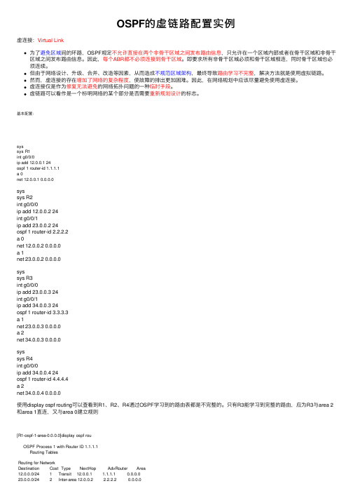
但由于⽹络设计、升级、合并、改造等因素,从⽽造成不规范区域架构,最终导致路由学习不完整,解决⽅法就是使⽤虚拟链路。
然⽽,虚连接的存在增加了⽹络的复杂程度,使故障的排出更加困难。
因此,在⽹络规划中应该尽量避免使⽤虚连接。
虚连接仅是作为修复⽆法避免的⽹络拓扑问题的⼀种临时⼿段。
虚链路可以看作是⼀个标明⽹络的某个部分是否需要重新规划设计的标志。
基本配置:syssys R1int g0/0/0ip add 12.0.0.1 24ospf 1 router-id 1.1.1.1a 0net 12.0.0.1 0.0.0.0syssys R2int g0/0/0ip add 12.0.0.2 24int g0/0/1ip add 23.0.0.2 24ospf 1 router-id 2.2.2.2a 0net 12.0.0.2 0.0.0.0a 1net 23.0.0.2 0.0.0.0syssys R3int g0/0/0ip add 23.0.0.3 24int g0/0/1ip add 34.0.0.3 24ospf 1 router-id 3.3.3.3a 1net 23.0.0.3 0.0.0.0a 2net 34.0.0.3 0.0.0.0syssys R4int g0/0/0ip add 34.0.0.4 24ospf 1 router-id 4.4.4.4a 2net 34.0.0.4 0.0.0.0使⽤display ospf routing可以查看到R1、R2、R4通过OSPF学习到的路由表都是不完整的。
实验6 配置OSPF虚链路

实验6 配置OSPF虚链路一、实验拓扑图,如图1.1所示:图1.1 OSPF虚链路实验拓扑图二、路由器初始配置:1.R1上的初始配置R1(config-line)#int s2/1R1(config-if)#ip add 12.0.0.1 255.255.255.0R1(config-if)#no shR1(config-if)#int lo 0R1(config-if)#ip add 1.1.1.1 255.255.255.0R1(config-if)#router os 1R1(config-router)#router-id 1.1.1.1R1(config-router)#net 1.1.1.1 0.0.0.0 a 0R1(config-router)#net 12.0.0.1 0.0.0.0 a 02.R2上的初始配置:R2(config-line)#int s2/1R2(config-if)#ip add 12.0.0.2 255.255.255.0R2(config-if)#no shR2(config-if)#int s2/2R2(config-if)#ip add 23.0.0.2 255.255.255.0R2(config-if)#no shR2(config-if)#int lo 0R2(config-if)#ip add 2.2.2.2 255.255.255.0R2(config-if)#router os 1R2(config-router)#router-id 2.2.2.2R2(config-router)#net 2.2.2.2 0.0.0.0 a 0R2(config-router)#net 12.0.0.2 0.0.0.0 a 0R2(config-router)#net 23.0.0.2 0.0.0.0 a 13.R3上的初始配置:R3(config-line)#int s2/1R3(config-if)#ip add 23.0.0.3 255.255.255.0R3(config-if)#no shR3(config-if)#int s2/2R3(config-if)#ip add 34.0.0.3 255.255.255.0R3(config-if)#no shR3(config-if)#int lo 0R3(config-if)#ip add 3.3.3.3 255.255.255.0R3(config-if)#router os 1R3(config-router)#router-id 3.3.3.3R3(config-router)#net 3.3.3.3 0.0.0.0 a 0R3(config-router)#net 23.0.0.3 0.0.0.0 a 1R3(config-router)#net 34.0.0.3 0.0.0.0 a 04.R4上的初始配置:R4(config-line)#int s2/1R4(config-if)#ip add 34.0.0.4 255.255.255.0R4(config-if)#no shR4(config-if)#int lo 0R4(config-if)#ip add 4.4.4.4 255.255.255.0R4(config-if)#router os 1R4(config-router)#router-id 4.4.4.4R4(config-router)#net 4.4.4.4 0.0.0.0 a 0R4(config-router)#net 34.0.0.4 0.0.0.0 a 05.在R1上查看路由表信息R1(config-router)#do sh ip routCodes: C - connected, S - static, R - RIP, M - mobile, B - BGPD - EIGRP, EX - EIGRP external, O - OSPF, IA - OSPF inter areaN1 - OSPF NSSA external type 1, N2 - OSPF NSSA external type 2E1 - OSPF external type 1, E2 - OSPF external type 2i - IS-IS, su - IS-IS summary, L1 - IS-IS level-1, L2 - IS-IS level-2ia - IS-IS inter area, * - candidate default, U - per-user static routeo - ODR, P - periodic downloaded static routeGateway of last resort is not set1.0.0.0/24 is subnetted, 1 subnetsC 1.1.1.0 is directly connected, Loopback02.0.0.0/32 is subnetted, 1 subnetsO 2.2.2.2 [110/65] via 12.0.0.2, 00:06:09, Serial2/123.0.0.0/24 is subnetted, 1 subnetsO IA 23.0.0.0 [110/128] via 12.0.0.2, 00:06:09, Serial2/112.0.0.0/24 is subnetted, 1 subnetsC 12.0.0.0 is directly connected, Serial2/1以上输出表明,R1不能获知分割开的Area 0的路由信息,需要将Area 0 连在一起。
- 1、下载文档前请自行甄别文档内容的完整性,平台不提供额外的编辑、内容补充、找答案等附加服务。
- 2、"仅部分预览"的文档,不可在线预览部分如存在完整性等问题,可反馈申请退款(可完整预览的文档不适用该条件!)。
- 3、如文档侵犯您的权益,请联系客服反馈,我们会尽快为您处理(人工客服工作时间:9:00-18:30)。
实验二OSPF虚链路一.实验目的理解OSPF虚链路原理及何时需要使用虚链路掌握OSPF虚链路配置方法(1)使用虚链路将区域连接到骨干区域的配置方法;(2)使用虚链路将不连续的区域0连接起来的配置方法二、实验拓扑图使用虚链路将区域连接到骨干区域的拓扑图使用虚链路将不连续的区域0连接起来的拓扑图三、实验步骤及要求(一)使用虚链路将区域连接到骨干区域1.R2、R3、R4配置OSPFR2(config)#router ospf 1R2(config-router)#network 172.16.255.4 0.0.0.3 area 2R2(config-router)#exitR2的f0/1接口先不要宣称networkR3(config)#router ospf 1R3(config-router)#network 172.16.255.4 0.0.0.3 area 2R3(config-router)#network 172.16.255.8 0.0.0.3 area 0R4(config)#router ospf 1R4(config-router)#network 172.16.255.8 0.0.0.3 area 0R4(config-router)#network 172.16.16.0 0.0.0.255 area 12.查看R2的路由表R2#show ip route172.16.0.0/16 is variably subnetted, 4 subnets, 2 masksC 172.16.255.0/30 is directly connected, FastEthernet0/1C 172.16.255.4/30 is directly connected, FastEthernet0/0O IA 172.16.255.8/30 [110/2] via 172.16.255.6, 00:06:42, FastEthernet0/0O IA 172.16.16.1/32 [110/3] via 172.16.255.6, 00:06:09, FastEthernet0/03.再次配置R1和R2的OSPF协议R1(config)#router ospf 1R1(config-router)#network 172.16.255.0 0.0.0.3 area 3R1(config-router)#network 172.16.1.0 0.0.0.255 area 3R1(config-router)#exitR2(config)#router ospf 1R2(config-router)#network 172.16.255.0 0.0.0.3 area 3R2(config-router)#exit4. 查看R1与R2的OSPF的邻居表R1#show ip ospf neighborNeighbor ID Pri State Dead Time Address Interface 172.16.255.5 1 FULL/BDR 00:00:39 172.16.255.2 FastEthernet0/0 R2#show ip ospf neighborNeighbor ID Pri State Dead Time Address Interface 172.16.255.9 1 FULL/BDR 00:00:36 172.16.255.6 FastEthernet0/0 172.16.1.1 1 FULL/DR 00:00:30 172.16.255.1 FastEthernet0/1 5. 查看R1的路由表R1#show ip route172.16.0.0/16 is variably subnetted, 2 subnets, 2 masksC 172.16.255.0/30 is directly connected, FastEthernet0/0C 172.16.1.0/24 is directly connected, Loopback0通过观察R1的路由表,R1的路由器无法学习到骨干区域、area 1和area 2区域的路由。
造成这个问题的主要原因是:area 3区域与骨干区域area 0被分割。
OSPF的区域配置规则是:普通区域必须与骨干区域直连。
6. 当有这种问题出现时,可以使用虚链路的配置方案解决。
使用虚链路可以确保非直连区域能够逻辑认为自己与骨干区域直连。
在R2和R3上进行如下虚链路的配置。
R2(config)#router ospf 1R2(config-router)#area 2 virtual-link 172.16.255.9R2(config-router)#exit命令中的area 2 指出有一条虚链路存在于区域2中。
virtual-link 172.16.255.9指出创建虚链路的对端R3路由器的router id。
R3(config)#router ospf 1R3(config-router)#area 2 virtual-link 172.16.255.5R3(config-router)#exit配置到R2路由器虚链路。
注意:使用router id,而不是接口ip.7.查看R1的路由表R1#show ip route172.16.0.0/16 is variably subnetted, 5 subnets, 3 masksC 172.16.255.0/30 is directly connected, FastEthernet0/0O IA 172.16.255.4/30 [110/2] via 172.16.255.2, 00:05:22, FastEthernet0/0O IA 172.16.255.8/30 [110/3] via 172.16.255.2, 00:03:04, FastEthernet0/0O IA 172.16.16.1/32 [110/4] via 172.16.255.2, 00:03:04, FastEthernet0/0C 172.16.1.0/24 is directly connected, Loopback0R1路由器已经正确的学习到其它区域的路由8. show ip ospf virtual-links查看OSPF虚链路的运行情况R2#show ip ospf virtual-linksVirtual Link OSPF_VL0 to router 172.16.255.9 is upRun as demand circuitDoNotAge LSA allowed.Transit area 2, via interface FastEthernet0/0, Cost of using 1Transmit Delay is 1 sec, State POINT_TO_POINT,Timer intervals configured, Hello 10, Dead 40, Wait 40, Retransmit 5Hello due in 00:00:09Adjacency State FULL (Hello suppressed)Index 1/3, retransmission queue length 0, number of retransmission 1First 0x0(0)/0x0(0) Next 0x0(0)/0x0(0)Last retransmission scan length is 1, maximum is 1Last retransmission scan time is 0 msec, maximum is 0 msecVirtual Link OSPF_VL0 to router 172.16.255.9 is up 指出OSPF邻居以及连接该邻居的链路处于up还是down状态Transit area 2 虚链路穿越的中转区域via interface FastEthernet0/0 端接虚链路的接口Cost of using 1 通过虚链路前往OSPF邻居的开销Transmit Delay is 1 sec 虚链路的传输延迟State POINT_TO_POINT OSPF邻居的状态Timer intervals configured 给链路配置的各种定时器值Hello due in 00:00:09 预期多久后将收到邻居的下一个Hello分组Adjacency State FULL 邻居之间的邻接关系状态(二)使用虚链路将不连续的区域0连接起来1.配置OSPF协议,注意区域号2.完成配置以后,查看R1-R4的路由表R3#show ip route172.16.0.0/16 is variably subnetted, 3 subnets, 2 masksC 172.16.255.4/30 is directly connected, Serial1/0C 172.16.255.8/30 is directly connected, Serial1/1O IA 172.16.16.1/32 [110/65] via 172.16.255.10, 00:05:16, Serial1/1R3仅仅学习到area 1区域的路由。
3.通过以上查看,可以发现,任何一台路由器都无法学习到完整的网络路由。
产生此问题的主要原因是:骨干0的区域被area 2分割,造成整个网络变成两个OSPF的自治系统。
所以相互之间都无法学习完整的路由。
4.在这种情况下,可以通过配置虚链路来解决骨干被分割的问题。
在R2与R3的路由器上实施如下配置:R2(config)#router ospf 1R2(config-router)#area 2 virtual-link 172.16.255.9R2(config-router)#exit命令中的area 2 指出有一条虚链路存在于区域2中。
virtual-link 172.16.255.9指出创建虚链路的对端R3路由器的router id。
R3(config)#router ospf 1R3(config-router)#area 2 virtual-link 172.16.255.5R3(config-router)#exit配置到R2路由器虚链路。
注意:使用router id,而不是接口ip.5.查看任意一台路由,确认路由学习情况。
本处选择R1路由器。
R1#show ip route172.16.0.0/16 is variably subnetted, 5 subnets, 3 masksC 172.16.255.0/30 is directly connected, Serial1/1O IA 172.16.255.4/30 [110/128] via 172.16.255.2, 00:01:08, Serial1/1O 172.16.255.8/30 [110/192] via 172.16.255.2, 00:01:08, Serial1/1O IA 172.16.16.1/32 [110/193] via 172.16.255.2, 00:01:08, Serial1/1 C 172.16.1.0/24 is directly connected, Loopback0此时,R1已经学习到完整的网络路由。
