T6316B-75DG中文资料
PMC-651T配电变压器保护测控装置用户说明书_V5.2
我们已经检查了本手册关于描述硬件和软件保持一致的内容。由于不可能完全消除差错,所以我们不 能保证完全的一致。本手册中的数据将定期审核,并在新一版的文件中做必要的修改,欢迎提出修改建议。 以后版本中的变动不再另行通知。
PMC-651T专业人士进行安装,对于因不遵守本手册的说明所引起 的故障,厂家将不承担任何责任。
重要提示 感谢您使用深圳市中电电力技术股份有限公司的产品。为了安全、正 确、高效地使用本装置,请您务必注意以下重要提示: 1) 本说明书仅适用于 PMC-651T 配电变压器保护测控装置。 2) 请仔细阅读本说明书,并按照说明书的说明设置、测试和操作。如 有随机资料,请以随机资料为准。 3) 为防止装置损坏,严禁带电插拔装置各插件、触摸印制电路板上的 芯片和器件。 4) 请使用合格的测试仪器和设备对装置进行试验和检测。 5) 装置如出现异常,请及时与本公司售后技术服务(400-8860-418) 联系。 6) 本装置的设置缺省密码是:0000。
2 技术指标...................................................................................................................................................................3 2.1 工作环境条件.............................................................................................................................................. 3 2.2 额定参数.......................................................................................................................................................3 2.3 准确度...........................................................................................................................................................3 2.4 遥信分辨率.................................................................................................................................................. 5 2.5 过载能力.......................................................................................................................................................5 2.6 继电器输出.................................................................................................................................................. 5 2.7 开关量输入.................................................................................................................................................. 5 2.8 外壳防护等级(IP).................................................................................................................................. 5 2.9 端子螺丝紧固力矩...................................................................................................................................... 5 2.10 电气绝缘性能............................................................................................................................................ 5 2.11 机械性能.....................................................................................................................................................6 2.12 电磁兼容性能............................................................................................................................................ 6
奥德维特说明书

PDA 系列产品的设计、制造、检查、试验及特性都应遵照适合的最新版IEC 和中国GB 标准及国际单位SI 制。
GB/T13730《地区电网数据采集与监控系统通用技术条件》GB/50171-92《电气装置安装工作盘、柜及二次回路接线施工及验收规范》DL/T630《交流采样远动终端通用技术条件》DL/478-92《静态继电保护及安全自动装置通用技术条件》GB/50062-92《电力装置的继电保护和自动装置设计规范》GB/T50063-2008《电力装置的电测量仪表装置设计规范》DL/T587-1996《微机继电保护装置运行管理规程》GB/T13729-2002《远动终端通用技术条件》GB/14285-93《继电保护和安全自动装置技术规程》GB/T17626.12-1998《振荡波抗扰度试验》GB/T17626.11-2008《电压暂降、短时中断和电压变化抗扰度试验》GB/T17626.10-1998《阻尼振荡磁场抗扰度试验》GB/T17626.8-2006《工频磁场的抗扰度试验》GB/T17626.6-2008《射频场感应的传导骚扰抗扰度》GB/T17626.5-2008《浪涌(冲击)抗扰度试验》GB/T17626.4-2008《电快速瞬变脉冲群抗扰度试验》GB/T17626.2-2006《静电放电抗扰度试验》GB/T 14047-1993《量度继电器和保护装置》GB 3836.3-2000《爆炸性气体环境用电气设备 第 3 部 分:增安型"e"》JB/T 10613-2006《数字式电动机综合保护装置》GB/T13850-1998《交流电量转换为模拟量或数字信号的电测量变送器》JJG596-1999《电子式电能表检定规程》GB/T17215.321-2008《静止式有功电能表(1级和2级)》GB/T 22264-2008《安装式数字显示电测量仪表》产品标准Contents 目 录A -01综合电力监控仪PDA-120系列B -13 三相智能型电力仪表 PDA-103系列C -31单相智能型电力仪表 PDA-101系列D -51 智能型电动机保护控制器 PDA-110MRK F -66参考设计图附录产品业绩G -73GB/T17215.322-2008《》静止式有功电能表(0.2S 级和0.5S 级)E -58 低压电动机保护装置 ADVP-1451产品简介功能详表产品特点PDA -120系列综合电力监控仪是北京奥德威特电力科技股份有限公司按IEC 国际标准开发,与当今国际先进技术同步的网络化综合电力监控仪表。
G631高级版维修手册V10_20140710资料

G631 高级版维修手册V1.0华为技术有限公司Huawei Technologies Co., Ltd.版权所有侵权必究All rights reserved修订记录目录第1章主板工作原理 (4)第2章主板器件位置图与物料BOM信息 (7)第3章维修流程指导 (10)3.1主机维修流程 (10)3.2多路端口下载工具加载指导(半擦FLASH) (11)3.3单机版写号工具指导 (13)3.4写定制信息指导(G631-T00项目暂无定制) (13)第4章高级维修环境工具清单 (14)第5章手机原理及故障分析 (15)5.1不开机故障 (15)5.1.1无电流(直流电源供电) (15)5.1.2小电流(直流电源供电) (17)5.1.3大电流(直流电源供电) (21)5.2重启定屏 (25)5.3自动关机死机 (27)5.3.1自动关机 (27)5.3.2死机 (28)5.4手机发烫,待机时间短 (30)5.5无铃声 (32)5.5.1喇叭本体坏 (32)5.5.2喇叭通路 (32)5.6无受话 (34)5.7无送话,送话声音小 (34)5.8无信号,信号弱 (36)5.9不识别卡 (39)5.9.1 SIM卡不识 (39)5.9.2 T卡不识别 (43)5.10不摄像 (43)5.11触摸屏失灵 (46)5.12不充电故障 (48)5.13耳机问题 (51)5.14FM (55)5.15GPS WIFI BT (58)5.16马达G-SENSOR侧键 (60)5.16.1马达 (60)5.16.2 G-SENSOR (61)5.16.3侧键 (62)第6章 PCB板和BGA芯片焊点指示图 (64)第1章主板工作原理手机原理框图及介绍MT6582为基带信号处理芯片,主要负责IMAGE,VIDEO,AUDIO, RF INTERFACES, CONECTIVITY信号输入,输出处理. 基带接口部分提供侧键、LCD、SD卡、蓝牙、CAMERA、TP等接口。
施耐德宝光微机保护产品选型手册说明书
Schneider Baoguang关于施耐德宝光施耐德(陕西)宝光电器有限公司(简称SSBEA或施耐德宝光)是施耐德电气有限公司与陕西宝光集团有限公司共同组建的一家专业从事中、系统及相关产品研发、生产和销售的中外合资企业。
高新科技园区。
在世界五百强企业与中国中压电器龙头企业的通力合作下,作为国内中压行业著名的“宝光”品牌真空断路器的唯一合法生产商,施耐德宝光秉承精益生产科学理念,凭借品质过硬、安全可靠的全系列高品质产品和覆盖用户全生命周期的完善服务,帮助用户实现卓越的生产运营绩效和市场竞争力,用品质的“不妥协”实现可持续发展之道。
我们致力于将施耐德宝光打造成为中国卓越和高效的中压断路器和系统的制造平台,依托自身的专业优势,为广大用户和合作伙伴提供领先的总成本和长期全面的安心保障。
目录V5系列新一代微机保护测控装置 (1)产品概述 (1)产品特点 (2)型号及功能说明 (3)保护功能 (4)测控功能 (6)技术参数 (7)典型接线图 (8)外形尺寸及面板开孔尺寸 (11)V5订货选型表 (12)V3系列微机保护测控装置 (13)产品概述 (13)产品特点 (14)型号及功能说明 (15)保护功能 (16)测控功能 (17)技术参数 (18)典型接线图 (19)外形尺寸及面板开孔尺寸 (21)V3订货选型表 (22)V3U微机综合保护装置 (23)产品概述 (23)型号及功能说明 (24)保护功能 (25)测控功能 (26)技术参数 (27)外形尺寸图/典型接线图 (28)后台系统 (29)系统总体结构 (30)V5系列新一代微机保护测控装置是一种用于测量、控制、保护、通讯一体化的智能设备,产品主要用于工业及能源领域对线路、变压器、电动机及电容器的保护测控。
此产品外观时尚、结构精巧、大屏幕液晶显示,图形化中文菜单,四位方向导航盘,操作快捷方便。
内部基于SOC芯片软件方案,32位处理器,并根据硬件进行深度改良优化的嵌入式操作系统,使CPU运行效率更高。
Q1E-17-元器件【缺少资料】

5微
MG80C196KB
5
控
6 制 SMJ320F240HFPM40 5
器
12 256×8
30
双通道 544
109
A/D 转换 器,监视
CMOS
B-1
CMOS B-1
GJB597A DESC/ DESC/
D40
D48 LCC68
9
SM320F2407APGEMEP
CMOS
DESC/
PQFP
生产厂家
772 所 INTEL INTEL 进口
QZJ840611 QZJ840611
DO-35 济半四厂 DO-35 济半四厂
备注
3
2CK75D
150
75
50 150 ≤1 ≤5
A4
QZJ840611
DO-35 济半四厂
4
2CK76D
200
75
50 200 ≤1 ≤5
A4
QZJ840611
型号
1 滤波器 HFB-CE03F
2
滤波器
MLLC807030-22 2KZW1ED3
3 EM I 滤波器 ZREM I-1.5A
4
磁珠
JMLCB2B2012-1 00B
主要性能参数
Vin
Ii
(V)
(A)
18~36
3.8
100
7
0~50
1.5
质量等级 A3
B1
技术标准 [总规范/详细规范]
Q/HW30312-2001 GJB1518-1992
型号
1 2
开关 二极
管
玻璃 封装
2CK50
2CK70C 2CK70E
75176B中文资料

PACKAGING INFORMATIONOrderable Device Status(1)PackageType PackageDrawingPins PackageQtyEco Plan(2)Lead/Ball Finish MSL Peak Temp(3)SN65176BD ACTIVE SOIC D875Green(RoHS&no Sb/Br)CU NIPDAU Level-1-260C-UNLIMSN65176BDE4ACTIVE SOIC D875Green(RoHS&no Sb/Br)CU NIPDAU Level-1-260C-UNLIMSN65176BDG4ACTIVE SOIC D875Green(RoHS&no Sb/Br)CU NIPDAU Level-1-260C-UNLIMSN65176BDR ACTIVE SOIC D82500Green(RoHS&no Sb/Br)CU NIPDAU Level-1-260C-UNLIMSN65176BDRE4ACTIVE SOIC D82500Green(RoHS&no Sb/Br)CU NIPDAU Level-1-260C-UNLIMSN65176BDRG4ACTIVE SOIC D82500Green(RoHS&no Sb/Br)CU NIPDAU Level-1-260C-UNLIMSN65176BP ACTIVE PDIP P850Pb-Free(RoHS)CU NIPDAU N/A for Pkg TypeSN65176BPE4ACTIVE PDIP P850Pb-Free(RoHS)CU NIPDAU N/A for Pkg TypeSN75176BD ACTIVE SOIC D875Green(RoHS&no Sb/Br)CU NIPDAU Level-1-260C-UNLIMSN75176BDE4ACTIVE SOIC D875Green(RoHS&no Sb/Br)CU NIPDAU Level-1-260C-UNLIMSN75176BDG4ACTIVE SOIC D875Green(RoHS&no Sb/Br)CU NIPDAU Level-1-260C-UNLIMSN75176BDR ACTIVE SOIC D82500Green(RoHS&no Sb/Br)CU NIPDAU Level-1-260C-UNLIMSN75176BDRE4ACTIVE SOIC D82500Green(RoHS&no Sb/Br)CU NIPDAU Level-1-260C-UNLIMSN75176BDRG4ACTIVE SOIC D82500Green(RoHS&no Sb/Br)CU NIPDAU Level-1-260C-UNLIMSN75176BP ACTIVE PDIP P850Pb-Free(RoHS)CU NIPDAU N/A for Pkg TypeSN75176BPE4ACTIVE PDIP P850Pb-Free(RoHS)CU NIPDAU N/A for Pkg TypeSN75176BPSR ACTIVE SO PS82000Green(RoHS&no Sb/Br)CU NIPDAU Level-1-260C-UNLIMSN75176BPSRG4ACTIVE SO PS82000Green(RoHS&no Sb/Br)CU NIPDAU Level-1-260C-UNLIM(1)The marketing status values are defined as follows:ACTIVE:Product device recommended for new designs.LIFEBUY:TI has announced that the device will be discontinued,and a lifetime-buy period is in effect.NRND:Not recommended for new designs.Device is in production to support existing customers,but TI does not recommend using this part in a new design.PREVIEW:Device has been announced but is not in production.Samples may or may not be available.OBSOLETE:TI has discontinued the production of the device.(2)Eco Plan-The planned eco-friendly classification:Pb-Free(RoHS),Pb-Free(RoHS Exempt),or Green(RoHS&no Sb/Br)-please check /productcontent for the latest availability information and additional product content details.TBD:The Pb-Free/Green conversion plan has not been defined.Pb-Free(RoHS):TI's terms"Lead-Free"or"Pb-Free"mean semiconductor products that are compatible with the current RoHS requirements for all6substances,including the requirement that lead not exceed0.1%by weight in homogeneous materials.Where designed to be soldered at high temperatures,TI Pb-Free products are suitable for use in specified lead-free processes.Pb-Free(RoHS Exempt):This component has a RoHS exemption for either1)lead-based flip-chip solder bumps used between the die andpackage,or2)lead-based die adhesive used between the die and leadframe.The component is otherwise considered Pb-Free(RoHS compatible)as defined above.Green(RoHS&no Sb/Br):TI defines"Green"to mean Pb-Free(RoHS compatible),and free of Bromine(Br)and Antimony(Sb)based flame retardants(Br or Sb do not exceed0.1%by weight in homogeneous material)(3)MSL,Peak Temp.--The Moisture Sensitivity Level rating according to the JEDEC industry standard classifications,and peak solder temperature.Important Information and Disclaimer:The information provided on this page represents TI's knowledge and belief as of the date that it is provided.TI bases its knowledge and belief on information provided by third parties,and makes no representation or warranty as to the accuracy of such information.Efforts are underway to better integrate information from third parties.TI has taken and continues to take reasonable steps to provide representative and accurate information but may not have conducted destructive testing or chemical analysis on incoming materials and chemicals.TI and TI suppliers consider certain information to be proprietary,and thus CAS numbers and other limited information may not be available for release.In no event shall TI's liability arising out of such information exceed the total purchase price of the TI part(s)at issue in this document sold by TI to Customer on an annual basis.TAPE AND REEL INFORMATIONDevice Package Pins Site ReelDiameter(mm)ReelWidth(mm)A0(mm)B0(mm)K0(mm)P1(mm)W(mm)Pin1QuadrantSN65176BDR D8FMX33012 6.4 5.2 2.1812Q1 SN75176BDR D8FMX33012 6.4 5.2 2.1812Q1 SN75176BPSR PS8MLA330168.2 6.6 2.51216Q1TAPE AND REEL BOX INFORMATIONDevice Package Pins Site Length(mm)Width(mm)Height(mm)SN65176BDR D8FMX338.1340.520.64SN75176BDR D8FMX338.1340.520.64SN75176BPSR PS8MLA342.9336.628.58IMPORTANT NOTICETexas Instruments Incorporated and its subsidiaries (TI)reserve the right to make corrections,modifications,enhancements,improvements,and other changes to its products and services at any time and to discontinue any product or service without notice.Customers should obtain the latest relevant information before placing orders and should verify that such information is current and complete.All products are sold subject to TI’s terms and conditions of sale supplied at the time of order acknowledgment.TI warrants performance of its hardware products to the specifications applicable at the time of sale in accordance with TI’s standard warranty.Testing and other quality control techniques are used to the extent TI deems necessary to support this warranty.Except where mandated by government requirements,testing of all parameters of each product is not necessarily performed.TI assumes no liability for applications assistance or customer product design.Customers are responsible for their products and applications using TI components.To minimize the risks associated with customer products and applications,customers should provide adequate design and operating safeguards.TI does not warrant or represent that any license,either express or implied,is granted under any TI patent right,copyright,mask work right,or other TI intellectual property right relating to any combination,machine,or process in which TI products or services are rmation published by TI regarding third-party products or services does not constitute a license from TI to use such products or services or a warranty or endorsement e of such information may require a license from a third party under the patents or other intellectual property of the third party,or a license from TI under the patents or other intellectual property of TI.Reproduction of information in TI data books or data sheets is permissible only if reproduction is without alteration and isaccompanied by all associated warranties,conditions,limitations,and notices.Reproduction of this information with alteration is an unfair and deceptive business practice.TI is not responsible or liable for such altered documentation.Resale of TI products or services with statements different from or beyond the parameters stated by TI for that product or service voids all express and any implied warranties for the associated TI product or service and is an unfair and deceptive business practice.TI is not responsible or liable for any such statements.TI products are not authorized for use in safety-critical applications (such as life support)where a failure of the TI product would reasonably be expected to cause severe personal injury or death,unless officers of the parties have executed an agreementspecifically governing such use.Buyers represent that they have all necessary expertise in the safety and regulatory ramifications of their applications,and acknowledge and agree that they are solely responsible for all legal,regulatory and safety-related requirements concerning their products and any use of TI products in such safety-critical applications,notwithstanding any applications-related information or support that may be provided by TI.Further,Buyers must fully indemnify TI and itsrepresentatives against any damages arising out of the use of TI products in such safety-critical applications.TI products are neither designed nor intended for use in military/aerospace applications or environments unless the TI products are specifically designated by TI as military-grade or "enhanced plastic."Only products designated by TI as military-grade meet military specifications.Buyers acknowledge and agree that any such use of TI products which TI has not designated as military-grade is solely at the Buyer's risk,and that they are solely responsible for compliance with all legal and regulatory requirements in connection with such use.TI products are neither designed nor intended for use in automotive applications or environments unless the specific TI products are designated by TI as compliant with ISO/TS 16949requirements.Buyers acknowledge and agree that,if they use any non-designated products in automotive applications,TI will not be responsible for any failure to meet such requirements.Following are URLs where you can obtain information on other Texas Instruments products and application solutions:ProductsApplications AmplifiersAudioDataConvertersAutomotiveDSPBroadband InterfaceDigital Control LogicMilitary Power MgmtOptical Networking MicrocontrollersSecurity RFIDTelephony Low PowerVideo &ImagingWireless Wireless Mailing Address:Texas Instruments,Post Office Box 655303,Dallas,Texas 75265Copyright ©2007,Texas Instruments Incorporated 元器件交易网。
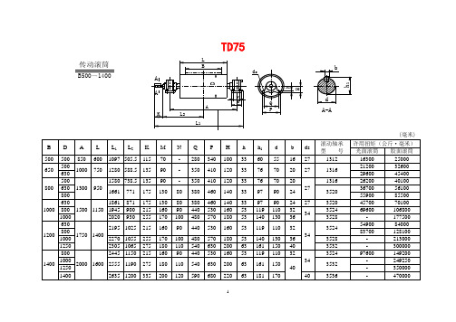
TD75、DTⅡ及DTⅡ(A)型滚筒
501
TD3A35
503
1000
630
TD4A14
442
TD4A24
467
TD4A34
471
800
TD4A15
682
TD4A25
715
TD4A35
719
1000
—
—
TD4A26
963
TD4A36
969
1250
630
TD5A14
660
TD5A24
691
TD5A34
696
800
TD5A15
759
33
76
70
20
27
1316
21200
32600
630
29600
45400
800
500
1300
950
1580
738.5
135
90
-
350
410
120
33
76
70
20
27
1316
26200
40100
630
1661
771
175
130
80
380
460
140
33
97
90
24
3520
36700
56100
800
1784
1400
—
—
TD6A28
2203
TD6A38
2216
说明:
1.滚筒为钢板焊接结构,分光面、胶面两种。
胶面又分铸胶和包胶两种。
TD1A13≈TD1A1.3≈ TD1A13
2.滚筒直径D在1000毫米以上者只有胶面滚
FGT综合布线产品手册

* 颜色、低烟无卤等可定制,每轴(305 米 ± 2%)
包装 纸箱 纸箱
工作温度 -20 ~ 60℃ -20 ~ 60℃
安装温度 0℃~ 60℃ 0℃~ 60℃
FGT 超五类室外阻水双绞线
超五类四线对阻水双绞线,线芯导体为 24AWG 的实芯裸铜,绝 缘层采用聚乙烯类高分子材料,外套阻水层加入具有防水功能 的线性低密度聚乙烯材料(LLDPE),可以防止潮气浸入,使用于 室外架空及管道使用,尺寸紧凑,易于施工。
铜缆类产品
六类屏蔽模块和线
FGT -48P-6L
专业 有效 保障
汇海科技综合布线系统
FGT六类屏蔽配线架
FGT-2P-J1L
汇海科技 营造完美生活!
FGT-24P-5L
FGT-6M-L
FGT 结构化综合布线系统
地址:上海市松江工业园区宝胜路 18 号 订购热线:4006669085 网址:
综合布线系统
Premises Distrbuted System
FGT INTRODUCTION
简介
FGT 是国际专业的结构化布线产品供应商,提供完整和多样 化的结构化布线解决方案,包括铜缆 CAT5E、CAT6、CAT6A、CAT7 综合布线系统、光纤布线及各种数据业务光端机产品。
FGT 不仅提供标准的产品,并拥有经验丰富的设计团队,为 客户提供产品设计及制造服务(OEM、ODM),以满足不同客户的需 求。
FGT 致力于提供高品质的通信产品,被客户信任是我们的首 要任务,FGT 开发和制造产品符和国际标准,如 ISO/IEC11801 标 准、ANSI/TIA 和 568B.2、IEEE、UL 认证、ROHS、CE 等。
FGT 提供高品质的产品,具有竞争力的价格,不同于其它品 牌公司提供高品质的产品也是高昂的价格,我们希望以降低经营 成本和利润来回馈我们的合作伙伴和消费者。
ZD6系列电动转辙机中文使用说明书
ZD6系列电动转辙机使用说明书西安铁路信号工厂编写说明《ZD6系列电动转辙机使用说明书》于1974年第一次编写,1979年第一次订正,1989年第二次订正,2001年第三次订正,2008年第四次订正。
表中的主副销抗挤切力等参数均依据TB/T1477-2005《ZD6系列电动转辙机》订正。
本次订正归入了相关的最新改进内容并对必需的增补、说明。
工厂保留设计更正而不早先在说明书中通知的权益。
西安铁路信号工厂版权所有未经同意不得摘录工厂保留更正权益2009年1月一、归纳1.1用途ZD6系列电动转辙机是用于铁路电气会合站场,用来改变道岔开通方向,锁闭道岔尖轨,反响道岔尖轨地点状态的设备。
1.2应用环境及分类工作环境:大气压力不低于70Kpa(海拔高度不超出3000m);四周空气温度-40℃~70℃;空气相对湿度不大于90%(25℃);四周无引起爆炸危险的有害气体。
电气运行电压DC160V电机额定转矩转辙机型号及分类1.3靠谱性ZD6系列转辙机实验室寿命为300,000次。
1.4安全要乞降警告使用限制本工厂对因为不遵守本手册的说明而以致的物件破坏和人身损害不负任何责任。
本产品的使用和操作人员一定先掌握本产品的相关性能并具备相关资格,技术协助、保护和维修工作一定在安全条件下进行,并一直遵守安全标准。
用户应保证人员具备安全要求,包含考虑人员身体状况。
产品在投入使用前,应检查四周相关环境能否安全,只有在完整正常的状况下可以启动。
转辙机保护时,一定在机器停运状态并需装备一定的个人防范装备。
本产品的使用不得违反相关的法律、法规、标准和规程。
风险及说明其余可能存在的风险见下表1,需强迫遵守相关规定。
表1风险及说明风险说明地域和阶段规定压碎用户应负责通地域:转辙机,1.未经同意的人员不得凑近尖轨。
夹伤过执行规定来尖轨和基本轨之2.负责保护的人员一定保证每次变换以前,控制压碎和夹间。
尖轨周边没有异物。
住风险阶段:转辙机操作比方:人员培训、特别作业程序、个人防范时期设备、警告表记等。
福建力得温控仪LD B 系列说明书

目录1.技术指标基本技术参数环境温度:-10~+55℃环境湿度:< 90%工作电压:220VAC (+10%,-15%)工作频率:50Hz或60Hz(±2Hz)测量范围:~℃或~℃测量精度:±1%FS(温控器级,传感器级)分辨力:℃风机输出总容量:6A/250VAC控制输出容量:5A/250VAC;5A/30VDC (阻性)温控器功耗:≤8W标准生产标准: JB/T7631-2005《变压器用电子温控器》通过的认证标准:ISO9001:2000国际质量管理体系认证通过的试验标准:IEC61000-4:1995 国际标准GB/T17626-1998《电磁兼容试验和测量技术》标准2.功能与型号分类注:具体选型请参考封底的产品外形照片及对应的型号,D 、E 、F 、G 、I 型是从具体功能上的划分,是属于功能字符,一般出现在型号的最后一位。
3.显 示D1:一位数码显示,显示测量相序及提示符 D2:四位数码显示,显示测量值及参数4.传感电缆总成D25传感电缆(三线制)D/E/F 型三路电缆连接示意图Pt100传感器电缆线LB C相D25传感器插头B相A相LAG/I 型四路电缆连接示意图D/E/F 型三路插头内部示意图 G/I 型四路插头内部示意图Pt100铂电阻是一种在~℃范围内线性较好的热电阻,它符合GB/T8622-97《工业铂电阻技术条件及分度表》B 级要求。
外形尺寸: Ф3×25mm 或Ф4×40mm Pt100铂电阻的电阻与温度的对应曲线:5.操作与显示-351122Pt100传感器电缆线LC、LdLBC相D25传感器插头B相A相d路LA温控器工作状态显示(以常规D型温控为例)按键功能6. 功能模块操作流程“黑匣子”功能进入该功能操作状态,可查看停电前瞬间各相绕组的温度值(仅G/I型号有d路)冷却风机激励(风机定时启停)功能注:时间间隔单位为小时,设定范围0~150。
新安装SGT-756微机变压器保护检验标准化作业指导书
变电所变压器微机保护检验标准化作业指导书保护型号:制造厂家:出厂日期:投运日期:辽宁省电力有限公司设备变更记录SGT-756型微机变压器保护检验标准化作业指导书目录1 装置检验要求及注意事项 (5)2 保护装置检验准备工作: (6)3 屏柜及装置的检查 (7)4 二次回路检验 (8)5装置通电检验 (9)6.开关量输入回路检验 (10)7.模数变换试验 (11)8.差动保护功能测试 (12)9高压侧后备保护定值校验 (13)10.低压侧后备保护定值检验 (15)11.保护带开关传动试验 (15)12.装置投运准备工作: (16)13带负荷测试 (16)附件一:继电保护二次工作保护压板及设备投切位置确认单 (19)附件二:继电保护二次工作安全措施票 (20)1 装置检验要求及注意事项1.1新安装装置的检验应按本检验报告规定的全部项目进行。
1.2 定期检验的全部检验项目按本检验报告中注“*”、“Δ”号的项目进行。
1.3 定期检验的部分检验项目按本检验报告中注“Δ”号的项目进行。
1.4 每2年进行一次部分检验,6年进行一次全部检验,结合一次设备停电进行断路器的传动试验。
1.5 装置检验详细步骤参照相应规程及生产厂家说明书。
1.6本作业指导书以书面的形式保存现场班组。
1.7 试验过程中的注意事项1.7.1 断开直流电源后才允许插、拔插件,插、拔插件必须有措施,防止因人身静电损坏集成电路芯片。
插、拔交流插件时应防止交流电流回路开路。
1.7.2 存放E2PROM芯片的窗口要用防紫外线的不干胶封死。
1.7.3 调试中不要更换芯片,确要更换芯片时应采用人体防静电接地措施,芯片插入的方向应正确,并保证接触可靠。
1.7.4 原则上不能使用电烙铁,试验中确需电烙铁时,应采用带接地线的烙铁或电烙铁断电后再焊接。
1.7.5 试验过程中,应注意不要将插件插错位置。
1.7.6 使用交流电源的电子仪器进行电路参数测试时,仪器外壳应与保护屏在同一点接地。
75176B中文资料

75176B中⽂资料PACKAGING INFORMATION Orderable Device Status(1)PackageType PackageDrawingPins PackageQtyEco Plan(2)Lead/Ball Finish MSL Peak Temp(3)SN65176BD ACTIVE SOIC D875Green(RoHS&no Sb/Br)CU NIPDAU Level-1-260C-UNLIMSN65176BDE4ACTIVE SOIC D875Green(RoHS&no Sb/Br)CU NIPDAU Level-1-260C-UNLIMSN65176BDG4ACTIVE SOIC D875Green(RoHS&no Sb/Br)CU NIPDAU Level-1-260C-UNLIMSN65176BDR ACTIVE SOIC D82500Green(RoHS& no Sb/Br)CU NIPDAU Level-1-260C-UNLIMSN65176BDRE4ACTIVE SOIC D82500Green(RoHS& no Sb/Br)CU NIPDAU Level-1-260C-UNLIMSN65176BDRG4ACTIVE SOIC D82500Green(RoHS& no Sb/Br)CU NIPDAU Level-1-260C-UNLIMSN65176BP ACTIVE PDIP P850Pb-Free (RoHS)CU NIPDAU N/A for Pkg TypeSN65176BPE4ACTIVE PDIP P850Pb-Free (RoHS)CU NIPDAU N/A for Pkg TypeSN75176BD ACTIVE SOIC D875Green(RoHS&no Sb/Br)CU NIPDAU Level-1-260C-UNLIMSN75176BDE4ACTIVE SOIC D875Green(RoHS&no Sb/Br)CU NIPDAU Level-1-260C-UNLIMSN75176BDG4ACTIVE SOIC D875Green(RoHS&no Sb/Br)CU NIPDAU Level-1-260C-UNLIMSN75176BDR ACTIVE SOIC D82500Green(RoHS& no Sb/Br)CU NIPDAU Level-1-260C-UNLIMSN75176BDRE4ACTIVE SOIC D82500Green(RoHS&no Sb/Br)CU NIPDAU Level-1-260C-UNLIMSN75176BDRG4ACTIVE SOIC D82500Green(RoHS&no Sb/Br)CU NIPDAU Level-1-260C-UNLIMSN75176BP ACTIVE PDIP P850Pb-Free(RoHS)CU NIPDAU N/A for Pkg TypeSN75176BPE4ACTIVE PDIP P850Pb-Free(RoHS)CU NIPDAU N/A for Pkg TypeSN75176BPSR ACTIVE SO PS82000Green(RoHS&no Sb/Br)CU NIPDAU Level-1-260C-UNLIMSN75176BPSRG4ACTIVE SO PS82000Green(RoHS&no Sb/Br)CU NIPDAU Level-1-260C-UNLIM(1)The marketing status values are defined as follows:ACTIVE:Product device recommended for new designs.LIFEBUY:TI has announced that the device will be discontinued,and a lifetime-buy period is in effect.NRND:Not recommended for new designs.Device is in production to support existing customers,but TI does not recommend using this part in a new design.PREVIEW:Device has been announced but is not in production.Samples may or may not be available.OBSOLETE:TI has discontinued the production of the device.(2)Eco Plan-The planned eco-friendly classification:Pb-Free(RoHS),Pb-Free(RoHS Exempt),or Green(RoHS&no Sb/Br)-please check /doc/7167b986cc22bcd126ff0c93.html /productcontent for the latest availability information and additional product content details.TBD:The Pb-Free/Green conversion plan has not been defined.Pb-Free(RoHS):TI's terms"Lead-Free"or"Pb-Free"mean semiconductor products that are compatible with the current RoHS requirements for all6substances,including the requirement that lead not exceed0.1%by weight in homogeneous materials.Where designed to be soldered at high temperatures,TI Pb-Free products are suitable for use in specified lead-free processes.Pb-Free(RoHS Exempt):This component has a RoHS exemption for either1)lead-based flip-chip solder bumps used between the die andpackage,or2)lead-based die adhesive used between the die and leadframe.The component is otherwise considered Pb-Free(RoHS compatible)as defined above.Green(RoHS&no Sb/Br):TI defines"Green"to mean Pb-Free(RoHS compatible),and free of Bromine(Br)and Antimony(Sb)based flame retardants(Br or Sb do not exceed0.1%by weight in homogeneous material)(3)MSL,Peak Temp.--The Moisture Sensitivity Level rating according to the JEDEC industry standard classifications,and peak soldertemperature.Important Information and Disclaimer:The information provided on this page represents TI's knowledge and belief as of the date that it is provided.TI bases its knowledge and belief on information provided by third parties,and makes no representation or warranty as to the accuracy of such information.Efforts are underway to better integrate information from third parties.TI has taken and continues to take reasonable steps to provide representative and accurate information but may not have conducted destructive testing or chemical analysis on incoming materials and chemicals.TI and TI suppliers consider certain information to be proprietary,and thus CAS numbers and other limited information may not be available for release.In no event shall TI's liability arising out of such information exceed the total purchase price of the TI part(s)at issue in this document sold by TI to Customer on an annual basis.TAPE AND REEL INFORMATIONDevice Package Pins Site ReelDiameter(mm)ReelWidth(mm)A0(mm)B0(mm)K0(mm)P1(mm)W(mm)Pin1QuadrantSN65176BDR D8FMX33012 6.4 5.2 2.1812Q1 SN75176BDR D8FMX33012 6.4 5.2 2.1812Q1 SN75176BPSR PS8MLA330168.2 6.6 2.51216Q1TAPE AND REEL BOX INFORMATIONDevice Package Pins Site Length(mm)Width(mm)Height(mm)SN65176BDR D8FMX338.1340.520.64SN75176BDR D8FMX338.1340.520.64SN75176BPSR PS8MLA342.9336.628.58。
电磁炉用功率管的型号 代换 参数

电磁炉用功率管的型号代换参数2007年07月28日星期六 12:05大量维修实践表明,电磁炉(灶)内的部分元器件因工作温度较高,工作电流较大,电压较高等,其故障或损坏概率也较高。
其中的场效应功率管损坏率最高。
但由于商业竞争激烈,一般都不随机附带图纸,加之电磁炉所采用的场效应功率管一般均为较新产品,这便给维修带来不便和困难。
下面笔者根据汇集来的相关资料,提供几种常用电磁炉场效应功率管及代换资料供参考。
电磁炉一般均采用N型沟道功率场效应管,其相关参数为BVCBO≥1600V,BVCEO≥1000V,PCM≥100W,ICM≥7A,HFE≥40。
常用的电磁炉用场效应管内部带阻尼二极管的型号有 GT40N150D、GT40T301、SEC·G40N150D、ZON120ND、GT40T101、SQD35JA等。
内部不带阻尼二极管的型号有BT40T101、SGL40N150/150D等。
在维修代换时,若采用不带阻尼二极管的功率场效应管,应在D、S极间加接一只阻尼二极管,该二极管必须是快恢复型阻尼二极管,其耐压应≥1500V。
加接时正极接S 极,负极接D极即可。
参考型号如S5J53、 BY4591500等。
在负载电磁线圈和功率管之间串一只100W的灯泡再通电试机,可以防止烧管。
GT40Q321,FGL40N150D, FGL60N170D, FGA25N120,SK25N120,G40N150D, FGA25N135,1MBH25D--120,GP20B120UD--E,IXGH20N120BDI,以上功率管内部都带阻尼管,耐压都在1200V以上电流在20A以上只要电流相差不多都可以互相代换。
SGW25N120,K15T120。
以上的管子内部不带阻尼,如果要代换一上功率管时可以在电路板上安装2个以上的阻尼二极管耐压1200V以上,电流在8A以上。
电磁炉的关键元器件介绍1、大功率管IGBT(H20T120)说明:(1)、IGBT为电磁炉电路控制核心元器件,使用温度为小于85℃。
SG(B)系列浸渍式H级绝缘干式变压器
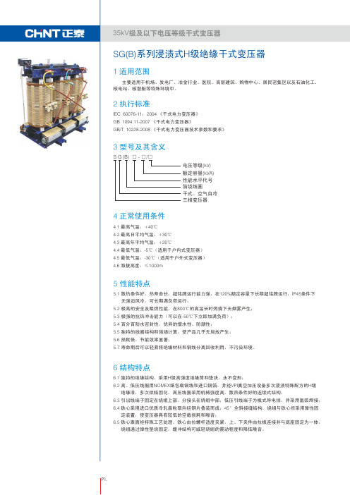
11
联结组 标号
Dyn11 或 Yyn0
空载 损耗 (W)
450 530 610 700 810 990 1100 1310 1510 1460 1710 1990 2350 2760 3400 4000 2760 3400 4000
不同的绝缘 耐热等级下的 负载损耗 (W)
H (145℃)
表10 短路 阻抗 (%)
4
6
8
7.2 浸渍式H级绝缘10系列10kV级无励磁调压配电变压器技术参数
额定 容量 (kVA)
100 125 160 200 250 315 400 500 630 630 800 1000 1250 1600 2000 2500 1600 2000 2500
电压组合
高压 (kV)
2250×1500×2400
SG(B)10-2500/10 1920 1270 1070 1070 625 313 205 2070 430 350 Ⅵ
2400×1500×2600
以上数据仅供参考,我公司保留更改数据的权利。我公司可根据用户要求提供非标产品
(请提供详细资料) 。
P3.
35kV级及以下电压等级干式变压器
%
W 标准误差范围
%
W 标准误差范围
%
□F □50Hz
□H □ 其它
□ 其它
LI
AC
/LI
AC
□400C
□其它
0C
□ 1000m
□其它
m
□GB6450
□IEC 60076-11 □DIN42523
□其它
□ 幅流式风机 □其它
□常规功能
□带RS485接
□带4-20mA输出
TCT7520-16D塔式起重机使用说明书(中文标准B版)

17 16 15 14 13 12 11 10
9 8 7 6 5 4 3 2 1 0
0
70m臂起重性能曲线
二倍率 四倍率
5 10 15 20 25 30 35 40 45 50 55 60 65 70 臂长(m)
65m 臂起重性能特性
幅度 (m)
最大起重性能 3.5~12.5 15.0 20.0 25.0
30.0
35.0
40
起重量 两倍率 3.5~25.4m, 8t
8.00
6.57
5.47
4.64
(t) 四倍率 3.5~13..4m, 16t 16.00 13.94 9.82 7.43
5.86
4.75
3.93
幅度 (m)
45.0
50.0
55.0
60.0
65.0
70.0
75.0
起重量 两倍率 4.01
着装置即可实现,起升高度可达 200m。
该机还有内爬式,用户需要请订货时说明 4. 变幅机构采用当今国际上最先进的变频无级调速方案,工作速度高,调速性能好, 工作更加平稳可靠; 5. 电气控制系统采用专业电器厂引进国外先进技术生产的电气元件,故障少,维修简 单,工作可靠; 6. 各种安全装置齐备, 且为机械式或机电一体化产品,适应于恶劣的施工环境,能 确保塔机工作可靠; 7. 设计在坚持切实符合国情,确保安全可靠原则的同时,尽可能地吸收采用国内外成 熟可靠的先进技术,来提高整机的技术水平, 采用成熟可靠的先进技术有:
出厂编号.: 出厂日期:
本公司致力于塔机的不断完善,满 足用户的各种需求,随机文件变化频 繁。
该编号的随机文件与该编号的主 机一一对应,切忌混用!即使是同型 号塔机,也不保证适用!
电气化铁道接触网零件第1部分接触线吊弦线夹

电气化铁道接触网零件第1部分接触线吊弦线夹TB 中华人民共和国铁道行业标准TB/T2075.1-2002电气化铁道接触网零部件第1部分:接触线吊弦线夹Fittings for overhead contact system of electrification railway Part1:Dropper clamp for contact wire2002-05-17发布 2002-08-01实施中华人民共和国铁道部发布TB/T 2075.1-2002前言TB/T 2075《电气化铁道接触网零部件》分为54个部分:——第1部分:接触线吊弦线夹;——第2部分:承力索吊弦线夹;——第3部分:双横承力索线夹;——第4部分:横承力索线夹;——第5部分:接触线中心锚结线夹;——第6部分:承力索中心锚结线夹;——第7部分:杵座鞍子;——第8部分:钩头鞍子;——第9部分:吊环;——第10部分:长吊环;——第11部分:耳环杆;——第12部分:悬吊滑轮;——第13部分:定位线夹;——第14部分:支持器;——第15部分:长支持器;——第16部分:定位环线夹;——第17部分:定位器;——第18部分:特型定位器;——第19部分:软定位器;——第20部分:特型软定位器;——第21部分:定位管;——第22部分:线岔;——第23部分:连接器;——第24部分:定位环;——第25部分:长定位环;——第26部分:套管双耳;——第27部分:套管铰环;——第28部分:铜接触线接头线夹;——第29部分:承力索接头线夹;——第30部分:UT型耐张线夹;——第31部分:杵座楔形线夹;——第32部分:双耳楔形线夹;——第33部分:双环杆;——第34部分:接触线终端锚固线夹;——第35部分:承力索终端锚固线夹;——第36部分:坠砣;TB/T 2075.1-2002——第37部分:补偿滑轮组;——第38部分:补偿棘轮;——第39部分:旋转腕臂底座;——第40部分:特型旋转腕臂底座;——第41部分:调节板;——第42部分:压管;——第43部分:杵环杆;——第44部分:软横跨固定底座;——第45部分:拉杆底座;——第46部分:特型拉杆底座;——第47部分:钢柱拉杆底座;——第48部分:腕臂;——第49部分:接触线电连接线夹(斜型);——第50部分:接触线电连接线夹(垂直型);——第51部分:电连接线夹(方型);——第52部分:电连接线夹(长方型);——第53部分:接地线夹;——第54部分:接地线连接线夹。
WGB-631说明书
WGB-631微机厂用变保护测控装置技术及使用说明书(ver-1.00)许继集团股份有限公司XJ GROUP CORPORATION CO.,LTD.WGB-631微机厂用变保护测控装置应用范围适用于3kV~10kV电压等级厂用变、所用变的保护及测控。
装置硬件后插拔方式,强弱电分离;加强型单元机箱按抗强振动、强干扰设计,可分散安装于开关柜上运行。
采用32位微机处理器,大容量的RAM和Flash Memory;数据处理、逻辑运算和信息存储能力强,运行速度快,可靠性高。
16位高精度AD,测量精度高。
可保存不少于80个最近发生的事件报告及运行报告。
采用图形液晶,中文显示,菜单式操作。
主要特点实时多任务操作系统,模块化编程;实时性好,可靠性高。
8套保护定值,定值区切换安全方便。
标准通信规约,方便与微机监控或保护管理机联网通讯。
完整的断路器操作回路,设置断路器遥控功能。
保护与测控一体化,单台装置完成间隔主要功能。
我公司保留对本说明书进行修改的权利;产品与说明书不符时,请参照实际产品说明。
2008.07 第一版印刷1装置简介 1 1.1 功能配置 1 1.2 主要特点 12技术指标 2 2.1 额定数据 2 2.2 功耗 2 2.3 环境条件 2 2.4 抗干扰性能 3 2.5 绝缘性能 3 2.6 机械性能 3 2.7 各元件工作范围及误差 3 2.8 测量精度 43装置硬件 4 3.1 机箱结构 4 3.2 主要插件 5 4保护原理 6 4.1 三段电流电压方向保护 6 4.2 过负荷保护 6 4.3 反时限过流保护 6 4.4 负序过流保护 7 4.5 高压侧零序保护 7 4.6 低压侧零序定时限保护 7 4.7 低压侧零序反时限保护 8 4.8 低电压保护 8 4.9 零序电压保护 8 4.10 PT断线告警 9 4.11 非电量保护 9 4.12 备用非电量保护 9 4.13 控制回路异常 10 4.14 手车位置异常告警 10 4.15 跳位异常告警 10 4.16 弹簧未储能告警 11 4.17 装置故障告警 114.18 遥测、遥信、遥控及遥脉功能 114.19 录波 114.20 G P S对时 115 定值范围及动作告警信息 11 5.1 压板整定信息 11 5.2 定值整定及说明 12 5.3 动作信息及说明 136 装置对外接线 15 6.1 装置对外接线 15 6.2 装置辅助电源 15 6.3 交流电流及电压输入 15 6.4 开入及开入电源 15 6.5 信号及控制回路 15 6.6 通信端子 167 人机界面说明 167.1 键盘说明 16 7.2 运行显示 16 7.3 菜单结构 16 7.4 菜单操作 17 7.5 浏览 18 7.6 记录 18 7.7 整定 19 7.8 调试 20 7.9 设置 22 7.10 版本 258 调试及异常处理 26 8.1 调试说明 26 8.2 程序检查 26 8.3 开关量输入检查 26 8.4 继电器回路检查 26 8.5 模拟量输入检查 26 8.6 整组试验 268.7 异常处理 269 IEC60870-5-103规约点表 27 9.1 保护动作故障信号 27 9.2 告警信号 27 9.3 状态信号 28 9.4 控制信号 28 9.5 遥测信号 29 9.6 电镀信号 29 9.7 总召唤信息 29 9.8 录波 2910 投运说明及注意事项 3011 贮存及保修 3012 供应成套性 3013 订货须知3114 附图1:装置面板布置图32附图2:装置背面端子图33附图3:装置接线示意图34附图4:控制回路原理图351.装置简介WGB-631微机厂用变保护装置主要适用于3~10kV电压等级小电流接地系统或小电阻接地系统中的厂用变、所用变或接地变的保护。
SG T756数字式变压器保护装置说明书(南网220kV版)_V1.00N2_印刷
* *
本说明书可能会被修改,请注意核对实际产品与说明书的版本是否相符 2012 年 3 月 第 1 版 第 1 次印刷
目
安全声明 版本声明
录
1 概述 ......................................................................................................................................................1 1.1 适用范围 .........................................................................................................................................1 1.2 保护配置 .........................................................................................................................................1 1.3 性能特点 .........................................................................................................................................1 2 技术性能及指标 ....................................................................................................................................3 2.1 额定电气参数 ..................................................................................................................................3 2.2 主要技术性能及指标 .......................................................................................................................3 2.3 环境大气条件 ..................................................................................................................................4 2.4 绝缘和耐湿热性能 ...........................................................................................................................4 2.5 电磁兼容性能 ..................................................................................................................................4 2.6 机械性能 .........................................................................................................................................5 3 保护原理说明 .........................................................................................................................................6 3.1 保护启动 .........................................................................................................................................6 3.2 差动保护 .........................................................................................................................................6 3.3 后备保护 .......................................................................................................................................12 3.4 告警功能及其它辅助功能 ..............................................................................................................22 4 硬件结构说明 ......................................................................................................................................24 4.1 装置安装结构、外观 .....................................................................................................................24 4.2 背板布置 .......................................................................................................................................25 4.3 背板布置及端子 ............................................................................................................................26 4.4 硬件系统框图及说明 .....................................................................................................................26 4.5 主要模件工作原理 .........................................................................................................................28 5 定值说明 .............................................................................................................................................30 5.1 220KV 电压等级定值整定 ..............................................................................................................30 6 使用说明 .............................................................................................................................................40 6.1 指示灯说明 ..................................................................................................................................40 6.2 人机界面总体结构 .......................................................................................................................40 6.3 人机界面使用说明 .......................................................................................................................41 7 订货须知及其他 ..................................................................................................................................51
特灵柜式空调技术要求

分体落地式房间空调器电控技术要求(特灵专用)宁波德贝里克电器有限公司二零零三年元月十号1 主题内容与适用范围本要求规定了德贝里克牌房间空调器用电控系统的设计、制造、储存、运输、交付及质量验收标准本要求适用于落地式房间空调器。
2 引用标准2.1 GB17625.1-1998 《低压电器及电子设备发出的谐波电流限值》2.2 QB/T2263-96 《房间空气调节器电子控制器》2.3 GB13028-91 《隔离变压器和安全隔离变压器》2.4 GB4706.32-1996 《家用和类似用途电器的安全热泵、空调器和除湿机的特殊要求》2.6 GB4798.1-86 《电工电子产品应用环境条件贮存》2.7 GB4798.2-84 《电工电子产品应用环境条件运输》3 技术指标3.1 工作电压范围:1Φ,165V—264V~50/60HZ;3.2 电路板工作环境3.2.1 工作温度范围:-10℃—+70℃;3.2.2 相对湿度:30—99%RH;3.2.3 大气压力:86kpa—106kpa3.3 储存温度范围:-20℃—+85℃;3.4 温度测量精度:±0.5℃;3.5 温度控制精度:±1℃;3.6 遥控器时钟精度:±10S/24H(每24小时走时误差小于10秒);3.7 遥控器遥控距离:8m/60°3.8 遥控器静态工作电流<20μA3.9 控制器成品必须通过EMC测试(2000V/2min)并应符合CCC要求;3.10 安全性能:控制器用安全件必须通过国家权威机构的安全认证;3.11 平均无故障工作时间(MTBF):30,000小时以上。
3.13 控制器消耗功率不大于标称值的10%(变压器次级电流<600mA)。
4 功能要求4.1 具有自动、制冷、除湿、通风、制热五种运行模式(单冷型为四种模式,无制热功能);4.2 具备三种除霜方式;a)室外传感器除霜:通过测量室外盘管传感器参数控制除霜。
- 1、下载文档前请自行甄别文档内容的完整性,平台不提供额外的编辑、内容补充、找答案等附加服务。
- 2、"仅部分预览"的文档,不可在线预览部分如存在完整性等问题,可反馈申请退款(可完整预览的文档不适用该条件!)。
- 3、如文档侵犯您的权益,请联系客服反馈,我们会尽快为您处理(人工客服工作时间:9:00-18:30)。
Low-Dropout, Constant-Current White LED Bias SupplyFEATURES• Up to 400mA LED Bias Current• 3% LED Current Matching• Simple LED Brightness Control• Low 0.05uA Shutdown Current• 2.7V to 5V Supply Voltage Range• SOP-8 Package and L ead-free• VSET Resistor Option :T6316A : External ResistorT6316B : 20, 85, 100, 125, 150, 175, 200, 250, 300 and 350mA OutputCurrent Option by InternalResistor• Build in Thermat Protect 160 °C Applications• Portable Communication Devices• Handheld Electronics• LED/Display Back Light Driver• LightingsGENERAL DESCRIPTIONThe T6316A/B low-dropout bias supply for white LEDs is a high-performance alternativeto the simple ballast resistors used in conventional white LED designs. The T6316A uses a single resistor to set the bias current forfour LEDs, which are matched to 3%. TheT6316B build in internal resistor to set the bias current for four LED. The T6316A/B advantages over ballast resistors include significantly better LED to LED bias matching, much lower bias variation with supply voltage variation, significantly lower dropout voltage,and in some applications, significantly improved efficiency. The T6316A/B is available in SOP-8 package and lead-free.PART NUMBER EXAMPLESPART NO. PACKAGEOutputCurrentVsetresistorT6316A-D SOP-8 - External T6316A-DGSOP-8lead-free- External T6316B-20D SOP-8 20mA InternalT6316B-20DGSOP-8lead-free20mA InternalT6316B-75D SOP-8 75mA InternalT6316B-75DGSOP-8lead-free75mA InternalT6316B-350D SOP-8 350mA InternalT6316B-350DGSOP-8lead-free350mA InternalPIN ARRANGEMENT(Top view)E N V S E T V D DL E D 1L E D 2L E D 3V S SL E D 4SOP-8 T6316A-DV D D V S S EN L E D 1L E D 2L E D 3V S SL E D 4SOP-8 T6316B-DPIN DESCRIPTIONSYMBOLT6316A T6316BDESCRIPTIONLED1 1 1LED 1 Cathode Connection. Current flowing into LED1 is 270/250 times the current flowing into SET. LED1 is high impedance when EN is low.LED2 2 2LED 2 Cathode Connection. Current flowing into LED1 is 270/250 times the currentflowing into SET. LED2 is high impedance when EN is low.LED3 3 3LED 3 Cathode Connection. Current flowing into LED1 is 270/250 times the currentflowing into SET. LED3 is high impedance when EN is low.LED4 4 4LED 4 Cathode Connection. Current flowing into LED1 is 270/250 times the currentflowing into SET. LED4 is high impedance when EN is low. VSS 5 5,6Ground VDD 6 7Power supply EN 7 8Enables PN6316A/B signal , H: Ative , L : Power Down . VSET 8 - VSET terminal is used to connect an external resistor to set output current. The current flowing into VSET sets the bias current intoeach LED by ILED_= 250 x ISET.VSET is internally biased to 0.306V. VSET is high impedance when EN is low.ABSOLUTE MAXIMUM RATINGSParameter Symbol Value UnitVoltage on any pin relative to GND V IN-0.3 to 6 V Operating Temperature Rang T A-40 to +85 °C Maximum Soldering Temperature (at leads, 10 sec) T LEAD 300 °CStorage Temperature Rang T S-65 to +150 °C Continuous Power Dissipation ( T A = +70°C ) 1 W Electrical Characteristics(TA = -40 to 85°C unless otherwise noted. Typical values are at TA =25°C,VEN =3.3V, VLED1 = VLED2= VLED3= VLED4= 1V)Symbol Description Conditions Min.Typ.MaxUnit V EN Operating voltage range EN is power supply input 2.7 5 VI SET SET input current range 1400 1600 uAT6316A 270I SETR SET to LED current ratio I LED / I SET, I SET=400uAT6316B 250A/AV SET SET bias voltage I SET=400uA, no loading 0.306 VI CM LED to LED current matching I SET=400uA, 100mA loading 3 %I LED Maximum LED sink current Each LED 350 400 mAI LSD LED leakage current inshutdownV LED1=V LED2=V LED3=V LED4= 3.3V,EN=GND, T A=+25°C, each LED0.01 1 uAV IH Input high voltage V EN >V IH for enable, VDD=5V 2.0 V V IL Input low voltage V EN <V IL for disable, VDD=5V0.8 V T TP Thermat Protect 160 °CFunctional DescriptionThe T6316A/B provides constant current bias supply for white LED designs. The T6316A uses a single resistor to set the bias current for up to four LEDs. LED bias currents are matched to 3%. The T6316B build in internal resistor to set the bias current for four LED. The T6316A/B offers several advantages over using ballast resistors, such as improved LED to LED brightness matching, lower bias variation with supply voltage changes, significantly lower dropout voltage, and in some applications, significantly improved efficiency.Enable InputEN powers the input of the T6316A/B. Drive EN high (> 2.0V) to enable the device; drive EN low (< 0.8V) to disable the device. Driving EN low forces LED1, LED2, LED3, LED4 and SET into a high-impedance state. Setting the Output CurrentSET controls the LED bias current. Current flowing into LED1, LED2, LED3 and LED4is 270/250 times greater than the current flowinginto SET. Set the output current as follows:T6316AI LED = 270 (0.306V / R SET )T6316BI LED = 250 (0.306V / R SET )Applications InformationVery Low-Cost, High-Efficiency Solution .A battery (single Li+ or three NiMH cells) powers the LEDs directly. This is the least expensive and most efficient architecture. Due to the high forward voltage of white LEDs, the LED brightness may dim slightly at the end of battery life. The T6316A/B current regulating architecture and low dropout greatly minimize this effect compared to using simple ballast resistors. The enable function of the T6316A/B turns on and off the LEDs.TYPICAL APPLICATION CIRCUITSVery low-cost, high-efficiency solutionPACKAGE DIMENSIONS8-LEAD SOPFDimension in mm Dimension in inchSymbolMin. Typ. Max. Min. Typ. Max.A 5.70 6.00 6.30 0.224 0.236 0.248A1 3.75 3.95 4.10 0.148 0.156 0.164B - - 5.13 - - 0.202B1 - 1.27 - - 0.050 -C - - 1.80 - - 0.071C1 1.35 1.55 1.75 0.052 0.061 0.069C2 0.10 - 0.25 0.001 - 0.004D 0.31 0.41 0.51 0.012 0.016 0.020E 0.30 0.50 0.70 0.012 0.020 0.028F 0.10 0.15 0.25 0.004 0.006 0.010J 2.23 REF 0.088 REFK 2.97 REF 0.117 REFH 0~8° 0~8°*Note :The thermal pad on the IC’s bottom has to be mounted on the copper foil.To eliminate the noise influence, the thermal pad is suggested to be connected to GND on PCB. In addition, desired thermal conductivity will be improved, if a heat-conducting copper foil on PCB is soldered with thermal pad. The thermal pad enhances the power dissipation. As a result, a large amount of current can be sunk safely in one package.。
