Dynamically generated heavy scalar fields in the Standard Model of Electroweak Interactions
压缩感知的稀疏定理
压缩感知的稀疏定理
压缩感知(Compressed Sensing,CS)是一种基于稀疏表示的采样理论。
在信号处理中,我们通常假设原始信号是稀疏的,即只有少数几个非零系数。
压缩感知的稀疏定理表明,对于一组随机或伪随机采样的信号,我们可以从少量的样本中恢复出原始信号的稀疏表示。
压缩感知的稀疏定理可以概括为:对于一个满足某些条件的稀疏信号,当采样率大于某个阈值时,该信号可以从少量的采样中被精确地重构出来。
这个条件被称为稀疏性条件,通常用L0范数或L1范数来描述。
压缩感知的稀疏定理在图像处理、通信系统、医学成像等领域具有广泛的应用前景。
它可以帮助减少数据采集和传输的成本,提高数据处理的效率和精度。
同时,压缩感知也面临着一些挑战,如如何选择适当的稀疏基函数、如何设计高效的压缩算法等。
基于matlab的岩石蠕变模型参数辨识算法设计 -回复
基于matlab的岩石蠕变模型参数辨识算法设计-回复问题,进行详细的解析和讨论。
1. 引言(200字左右)在地质工程领域,岩石蠕变是指岩石在持续加载下出现的时间依赖性变形现象。
岩石蠕变模型参数的准确辨识对于地质工程设计和安全评估具有重要意义。
现有的岩石蠕变模型参数辨识方法依赖于大量的试验数据和复杂的计算过程,这导致其效率较低且不易实施。
本文将设计一种基于matlab 的岩石蠕变模型参数辨识算法,旨在提高参数辨识的效率和准确性。
2. 岩石蠕变模型简介(300字左右)岩石蠕变模型是用来描述岩石在持续加载下发生时间依赖性变形的数学模型。
常见的蠕变模型有Maxwell模型、Kelvin模型和Burgers模型等。
这些蠕变模型通常包含多个参数,例如弹性模量、粘弹性模量、松弛时间等。
准确辨识这些参数可以为地质工程提供重要的参考数据,例如预测岩石的变形、稳定性和寿命等。
3. 岩石蠕变模型参数辨识算法设计(400字左右)(1)数据采集:首先,需要采集一系列的岩石蠕变试验数据。
这些数据通常包含加载时间、加载程度、应变等信息。
数据收集的质量和数量对参数辨识的准确性至关重要。
(2)建立数学模型:根据采集到的试验数据,可以建立用于参数辨识的数学模型。
典型的模型可以是由一系列串联或并联的弹簧和阻尼器组成。
例如,Kelvin模型可以表示为一个弹簧和一个阻尼器串联的结构。
(3)参数辨识算法:基于matlab平台,可以设计基于优化算法的参数辨识方法。
典型的参数优化算法包括遗传算法、粒子群优化算法等。
这些算法可以自动搜索最优参数组合,使得模型预测结果与实际试验数据的误差最小化。
4. 算法的实施和结果分析(400字左右)在实际应用中,可以将设计好的基于matlab的岩石蠕变模型参数辨识算法应用于实际的蠕变试验数据。
通过该算法,可以辨识蠕变模型中的各个参数。
通过与实际试验数据进行对比,可以评估算法的准确性和实用性。
同时,还可以进行参数辨识结果的灵敏度分析。
Autodesk Nastran 2023 参考手册说明书
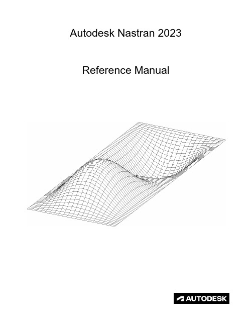
FILESPEC ............................................................................................................................................................ 13
DISPFILE ............................................................................................................................................................. 11
File Management Directives – Output File Specifications: .............................................................................. 5
BULKDATAFILE .................................................................................................................................................... 7
CJJ 169-2011 城镇道路路面设计规范
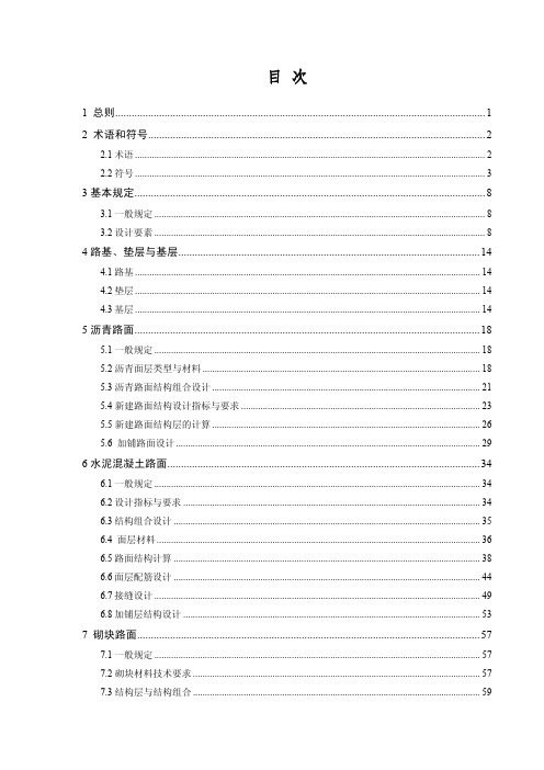
3 基本规定................................................................................................................................ 8
3.1 一般规定 ......................................................................................................................................... 8 3.2 设计要素 ......................................................................................................................................... 8
2.1 术语 ................................................................................................................................................. 2 2.2 符号 ................................................................................................................................................. 3
6 水泥混凝土路面.................................................................................................................. 34
核范数优化下的多表征挤压激励自适应网络
核范数优化下的多表征挤压激励自适应网络谭茜成;郭涛;李鸿;朱新远;邹俊颖;夏青【期刊名称】《小型微型计算机系统》【年(卷),期】2022(43)3【摘要】多表征自适应网络(MRAN)用于无监督学习取得了显著成效.但MRAN的特征提取只关注了域在空间结构上的联系而忽略了特征通道之间的联系,在进行无监督领域自适应(UDA)分类时,决策边界附近存在大量混淆数据的情况,当使用信息熵最小化对混淆数据进行分类时,往往会产生错误分类.针对这一问题,提出了基于批量核范数最大化的多表征挤压激励自适应网络(Multi-Representation Squeeze-Excitation Adaptation Network_Batch Kernel NormMaximization,MRSEAN_BNM).该网络采用挤压激励注意力机制对多表征特征进行重标定,以强化重要的表征特征,采用条件最大均值差异(CMMD)拉近源域和目标域的特征分布距离,并通过最大化目标域分类输出矩阵的核范数以约束决策边界的混淆数据,达到提升域适应图像分类精度的效果.在基于公开数据集的域适应下的图像分类、可视化结果实验结果表明,MRSEAN_BNM分类精度有明显提升.【总页数】6页(P598-603)【作者】谭茜成;郭涛;李鸿;朱新远;邹俊颖;夏青【作者单位】四川师范大学计算机科学学院【正文语种】中文【中图分类】TP181【相关文献】1.基于范数优化的对角加载稳健自适应波束形成2.改进的自适应权值核范数最小化去噪算法3.复杂环境下采场结构参数优化与自适应表征分析4.基于截断核范数低秩分解的自适应字典学习算法5.基于P范数的核最小对数绝对差自适应滤波算法因版权原因,仅展示原文概要,查看原文内容请购买。
Glider Flying Handbook说明书

Glider Flying Handbook2013U.S. Department of TransportationFEDERAL AVIATION ADMINISTRATIONFlight Standards Servicei iPrefaceThe Glider Flying Handbook is designed as a technical manual for applicants who are preparing for glider category rating and for currently certificated glider pilots who wish to improve their knowledge. Certificated flight instructors will find this handbook a valuable training aid, since detailed coverage of aeronautical decision-making, components and systems, aerodynamics, flight instruments, performance limitations, ground operations, flight maneuvers, traffic patterns, emergencies, soaring weather, soaring techniques, and cross-country flight is included. Topics such as radio navigation and communication, use of flight information publications, and regulations are available in other Federal Aviation Administration (FAA) publications.The discussion and explanations reflect the most commonly used practices and principles. Occasionally, the word “must” or similar language is used where the desired action is deemed critical. The use of such language is not intended to add to, interpret, or relieve a duty imposed by Title 14 of the Code of Federal Regulations (14 CFR). Persons working towards a glider rating are advised to review the references from the applicable practical test standards (FAA-G-8082-4, Sport Pilot and Flight Instructor with a Sport Pilot Rating Knowledge Test Guide, FAA-G-8082-5, Commercial Pilot Knowledge Test Guide, and FAA-G-8082-17, Recreational Pilot and Private Pilot Knowledge Test Guide). Resources for study include FAA-H-8083-25, Pilot’s Handbook of Aeronautical Knowledge, FAA-H-8083-2, Risk Management Handbook, and Advisory Circular (AC) 00-6, Aviation Weather For Pilots and Flight Operations Personnel, AC 00-45, Aviation Weather Services, as these documents contain basic material not duplicated herein. All beginning applicants should refer to FAA-H-8083-25, Pilot’s Handbook of Aeronautical Knowledge, for study and basic library reference.It is essential for persons using this handbook to become familiar with and apply the pertinent parts of 14 CFR and the Aeronautical Information Manual (AIM). The AIM is available online at . The current Flight Standards Service airman training and testing material and learning statements for all airman certificates and ratings can be obtained from .This handbook supersedes FAA-H-8083-13, Glider Flying Handbook, dated 2003. Always select the latest edition of any publication and check the website for errata pages and listing of changes to FAA educational publications developed by the FAA’s Airman Testing Standards Branch, AFS-630.This handbook is available for download, in PDF format, from .This handbook is published by the United States Department of Transportation, Federal Aviation Administration, Airman Testing Standards Branch, AFS-630, P.O. Box 25082, Oklahoma City, OK 73125.Comments regarding this publication should be sent, in email form, to the following address:********************************************John M. AllenDirector, Flight Standards Serviceiiii vAcknowledgmentsThe Glider Flying Handbook was produced by the Federal Aviation Administration (FAA) with the assistance of Safety Research Corporation of America (SRCA). The FAA wishes to acknowledge the following contributors: Sue Telford of Telford Fishing & Hunting Services for images used in Chapter 1JerryZieba () for images used in Chapter 2Tim Mara () for images used in Chapters 2 and 12Uli Kremer of Alexander Schleicher GmbH & Co for images used in Chapter 2Richard Lancaster () for images and content used in Chapter 3Dave Nadler of Nadler & Associates for images used in Chapter 6Dave McConeghey for images used in Chapter 6John Brandon (www.raa.asn.au) for images and content used in Chapter 7Patrick Panzera () for images used in Chapter 8Jeff Haby (www.theweatherprediction) for images used in Chapter 8National Soaring Museum () for content used in Chapter 9Bill Elliot () for images used in Chapter 12.Tiffany Fidler for images used in Chapter 12.Additional appreciation is extended to the Soaring Society of America, Inc. (), the Soaring Safety Foundation, and Mr. Brad Temeyer and Mr. Bill Martin from the National Oceanic and Atmospheric Administration (NOAA) for their technical support and input.vv iPreface (iii)Acknowledgments (v)Table of Contents (vii)Chapter 1Gliders and Sailplanes ........................................1-1 Introduction....................................................................1-1 Gliders—The Early Years ..............................................1-2 Glider or Sailplane? .......................................................1-3 Glider Pilot Schools ......................................................1-4 14 CFR Part 141 Pilot Schools ...................................1-5 14 CFR Part 61 Instruction ........................................1-5 Glider Certificate Eligibility Requirements ...................1-5 Common Glider Concepts ..............................................1-6 Terminology...............................................................1-6 Converting Metric Distance to Feet ...........................1-6 Chapter 2Components and Systems .................................2-1 Introduction....................................................................2-1 Glider Design .................................................................2-2 The Fuselage ..................................................................2-4 Wings and Components .............................................2-4 Lift/Drag Devices ...........................................................2-5 Empennage .....................................................................2-6 Towhook Devices .......................................................2-7 Powerplant .....................................................................2-7 Self-Launching Gliders .............................................2-7 Sustainer Engines .......................................................2-8 Landing Gear .................................................................2-8 Wheel Brakes .............................................................2-8 Chapter 3Aerodynamics of Flight .......................................3-1 Introduction....................................................................3-1 Forces of Flight..............................................................3-2 Newton’s Third Law of Motion .................................3-2 Lift ..............................................................................3-2The Effects of Drag on a Glider .....................................3-3 Parasite Drag ..............................................................3-3 Form Drag ...............................................................3-3 Skin Friction Drag ..................................................3-3 Interference Drag ....................................................3-5 Total Drag...................................................................3-6 Wing Planform ...........................................................3-6 Elliptical Wing ........................................................3-6 Rectangular Wing ...................................................3-7 Tapered Wing .........................................................3-7 Swept-Forward Wing ..............................................3-7 Washout ..................................................................3-7 Glide Ratio .................................................................3-8 Aspect Ratio ............................................................3-9 Weight ........................................................................3-9 Thrust .........................................................................3-9 Three Axes of Rotation ..................................................3-9 Stability ........................................................................3-10 Flutter .......................................................................3-11 Lateral Stability ........................................................3-12 Turning Flight ..............................................................3-13 Load Factors .................................................................3-13 Radius of Turn ..........................................................3-14 Turn Coordination ....................................................3-15 Slips ..........................................................................3-15 Forward Slip .........................................................3-16 Sideslip .................................................................3-17 Spins .........................................................................3-17 Ground Effect ...............................................................3-19 Chapter 4Flight Instruments ...............................................4-1 Introduction....................................................................4-1 Pitot-Static Instruments ..................................................4-2 Impact and Static Pressure Lines................................4-2 Airspeed Indicator ......................................................4-2 The Effects of Altitude on the AirspeedIndicator..................................................................4-3 Types of Airspeed ...................................................4-3Table of ContentsviiAirspeed Indicator Markings ......................................4-5 Other Airspeed Limitations ........................................4-6 Altimeter .....................................................................4-6 Principles of Operation ...........................................4-6 Effect of Nonstandard Pressure andTemperature............................................................4-7 Setting the Altimeter (Kollsman Window) .............4-9 Types of Altitude ......................................................4-10 Variometer................................................................4-11 Total Energy System .............................................4-14 Netto .....................................................................4-14 Electronic Flight Computers ....................................4-15 Magnetic Compass .......................................................4-16 Yaw String ................................................................4-16 Inclinometer..............................................................4-16 Gyroscopic Instruments ...............................................4-17 G-Meter ........................................................................4-17 FLARM Collision Avoidance System .........................4-18 Chapter 5Glider Performance .............................................5-1 Introduction....................................................................5-1 Factors Affecting Performance ......................................5-2 High and Low Density Altitude Conditions ...........5-2 Atmospheric Pressure .............................................5-2 Altitude ...................................................................5-3 Temperature............................................................5-3 Wind ...........................................................................5-3 Weight ........................................................................5-5 Rate of Climb .................................................................5-7 Flight Manuals and Placards ..........................................5-8 Placards ......................................................................5-8 Performance Information ...........................................5-8 Glider Polars ...............................................................5-8 Weight and Balance Information .............................5-10 Limitations ...............................................................5-10 Weight and Balance .....................................................5-12 Center of Gravity ......................................................5-12 Problems Associated With CG Forward ofForward Limit .......................................................5-12 Problems Associated With CG Aft of Aft Limit ..5-13 Sample Weight and Balance Problems ....................5-13 Ballast ..........................................................................5-14 Chapter 6Preflight and Ground Operations .......................6-1 Introduction....................................................................6-1 Assembly and Storage Techniques ................................6-2 Trailering....................................................................6-3 Tiedown and Securing ................................................6-4Water Ballast ..............................................................6-4 Ground Handling........................................................6-4 Launch Equipment Inspection ....................................6-5 Glider Preflight Inspection .........................................6-6 Prelaunch Checklist ....................................................6-7 Glider Care .....................................................................6-7 Preventive Maintenance .............................................6-8 Chapter 7Launch and Recovery Procedures and Flight Maneuvers ............................................................7-1 Introduction....................................................................7-1 Aerotow Takeoff Procedures .........................................7-2 Signals ........................................................................7-2 Prelaunch Signals ....................................................7-2 Inflight Signals ........................................................7-3 Takeoff Procedures and Techniques ..........................7-3 Normal Assisted Takeoff............................................7-4 Unassisted Takeoff.....................................................7-5 Crosswind Takeoff .....................................................7-5 Assisted ...................................................................7-5 Unassisted...............................................................7-6 Aerotow Climb-Out ....................................................7-6 Aerotow Release.........................................................7-8 Slack Line ...................................................................7-9 Boxing the Wake ......................................................7-10 Ground Launch Takeoff Procedures ............................7-11 CG Hooks .................................................................7-11 Signals ......................................................................7-11 Prelaunch Signals (Winch/Automobile) ...............7-11 Inflight Signals ......................................................7-12 Tow Speeds ..............................................................7-12 Automobile Launch ..................................................7-14 Crosswind Takeoff and Climb .................................7-14 Normal Into-the-Wind Launch .................................7-15 Climb-Out and Release Procedures ..........................7-16 Self-Launch Takeoff Procedures ..............................7-17 Preparation and Engine Start ....................................7-17 Taxiing .....................................................................7-18 Pretakeoff Check ......................................................7-18 Normal Takeoff ........................................................7-19 Crosswind Takeoff ...................................................7-19 Climb-Out and Shutdown Procedures ......................7-19 Landing .....................................................................7-21 Gliderport/Airport Traffic Patterns and Operations .....7-22 Normal Approach and Landing ................................7-22 Crosswind Landing ..................................................7-25 Slips ..........................................................................7-25 Downwind Landing ..................................................7-27 After Landing and Securing .....................................7-27viiiPerformance Maneuvers ..............................................7-27 Straight Glides ..........................................................7-27 Turns.........................................................................7-28 Roll-In ...................................................................7-29 Roll-Out ................................................................7-30 Steep Turns ...........................................................7-31 Maneuvering at Minimum Controllable Airspeed ...7-31 Stall Recognition and Recovery ...............................7-32 Secondary Stalls ....................................................7-34 Accelerated Stalls .................................................7-34 Crossed-Control Stalls ..........................................7-35 Operating Airspeeds .....................................................7-36 Minimum Sink Airspeed ..........................................7-36 Best Glide Airspeed..................................................7-37 Speed to Fly ..............................................................7-37 Chapter 8Abnormal and Emergency Procedures .............8-1 Introduction....................................................................8-1 Porpoising ......................................................................8-2 Pilot-Induced Oscillations (PIOs) ..............................8-2 PIOs During Launch ...................................................8-2 Factors Influencing PIOs ........................................8-2 Improper Elevator Trim Setting ..............................8-3 Improper Wing Flaps Setting ..................................8-3 Pilot-Induced Roll Oscillations During Launch .........8-3 Pilot-Induced Yaw Oscillations During Launch ........8-4 Gust-Induced Oscillations ..............................................8-5 Vertical Gusts During High-Speed Cruise .................8-5 Pilot-Induced Pitch Oscillations During Landing ......8-6 Glider-Induced Oscillations ...........................................8-6 Pitch Influence of the Glider Towhook Position ........8-6 Self-Launching Glider Oscillations During Powered Flight ...........................................................8-7 Nosewheel Glider Oscillations During Launchesand Landings ..............................................................8-7 Tailwheel/Tailskid Equipped Glider Oscillations During Launches and Landings ..................................8-8 Aerotow Abnormal and Emergency Procedures ............8-8 Abnormal Procedures .................................................8-8 Towing Failures........................................................8-10 Tow Failure With Runway To Land and Stop ......8-11 Tow Failure Without Runway To Land BelowReturning Altitude ................................................8-11 Tow Failure Above Return to Runway Altitude ...8-11 Tow Failure Above 800' AGL ..............................8-12 Tow Failure Above Traffic Pattern Altitude .........8-13 Slack Line .................................................................8-13 Ground Launch Abnormal and Emergency Procedures ....................................................................8-14 Abnormal Procedures ...............................................8-14 Emergency Procedures .............................................8-14 Self-Launch Takeoff Emergency Procedures ..............8-15 Emergency Procedures .............................................8-15 Spiral Dives ..................................................................8-15 Spins .............................................................................8-15 Entry Phase ...............................................................8-17 Incipient Phase .........................................................8-17 Developed Phase ......................................................8-17 Recovery Phase ........................................................8-17 Off-Field Landing Procedures .....................................8-18 Afterlanding Off Field .............................................8-20 Off-Field Landing Without Injury ........................8-20 Off-Field Landing With Injury .............................8-20 System and Equipment Malfunctions ..........................8-20 Flight Instrument Malfunctions ................................8-20 Airspeed Indicator Malfunctions ..........................8-21 Altimeter Malfunctions .........................................8-21 Variometer Malfunctions ......................................8-21 Compass Malfunctions .........................................8-21 Glider Canopy Malfunctions ....................................8-21 Broken Glider Canopy ..........................................8-22 Frosted Glider Canopy ..........................................8-22 Water Ballast Malfunctions ......................................8-22 Retractable Landing Gear Malfunctions ..................8-22 Primary Flight Control Systems ...............................8-22 Elevator Malfunctions ..........................................8-22 Aileron Malfunctions ............................................8-23 Rudder Malfunctions ............................................8-24 Secondary Flight Controls Systems .........................8-24 Elevator Trim Malfunctions .................................8-24 Spoiler/Dive Brake Malfunctions .........................8-24 Miscellaneous Flight System Malfunctions .................8-25 Towhook Malfunctions ............................................8-25 Oxygen System Malfunctions ..................................8-25 Drogue Chute Malfunctions .....................................8-25 Self-Launching Gliders ................................................8-26 Self-Launching/Sustainer Glider Engine Failure During Takeoff or Climb ..........................................8-26 Inability to Restart a Self-Launching/SustainerGlider Engine While Airborne .................................8-27 Self-Launching Glider Propeller Malfunctions ........8-27 Self-Launching Glider Electrical System Malfunctions .............................................................8-27 In-flight Fire .............................................................8-28 Emergency Equipment and Survival Gear ...................8-28 Survival Gear Checklists ..........................................8-28 Food and Water ........................................................8-28ixClothing ....................................................................8-28 Communication ........................................................8-29 Navigation Equipment ..............................................8-29 Medical Equipment ..................................................8-29 Stowage ....................................................................8-30 Parachute ..................................................................8-30 Oxygen System Malfunctions ..................................8-30 Accident Prevention .....................................................8-30 Chapter 9Soaring Weather ..................................................9-1 Introduction....................................................................9-1 The Atmosphere .............................................................9-2 Composition ...............................................................9-2 Properties ....................................................................9-2 Temperature............................................................9-2 Density ....................................................................9-2 Pressure ...................................................................9-2 Standard Atmosphere .................................................9-3 Layers of the Atmosphere ..........................................9-4 Scale of Weather Events ................................................9-4 Thermal Soaring Weather ..............................................9-6 Thermal Shape and Structure .....................................9-6 Atmospheric Stability .................................................9-7 Air Masses Conducive to Thermal Soaring ...................9-9 Cloud Streets ..............................................................9-9 Thermal Waves...........................................................9-9 Thunderstorms..........................................................9-10 Lifted Index ..........................................................9-12 K-Index .................................................................9-12 Weather for Slope Soaring .......................................9-14 Mechanism for Wave Formation ..............................9-16 Lift Due to Convergence ..........................................9-19 Obtaining Weather Information ...................................9-21 Preflight Weather Briefing........................................9-21 Weather-ReIated Information ..................................9-21 Interpreting Weather Charts, Reports, andForecasts ......................................................................9-23 Graphic Weather Charts ...........................................9-23 Winds and Temperatures Aloft Forecast ..............9-23 Composite Moisture Stability Chart .....................9-24 Chapter 10Soaring Techniques ..........................................10-1 Introduction..................................................................10-1 Thermal Soaring ...........................................................10-2 Locating Thermals ....................................................10-2 Cumulus Clouds ...................................................10-2 Other Indicators of Thermals ................................10-3 Wind .....................................................................10-4 The Big Picture .....................................................10-5Entering a Thermal ..............................................10-5 Inside a Thermal.......................................................10-6 Bank Angle ...........................................................10-6 Speed .....................................................................10-6 Centering ...............................................................10-7 Collision Avoidance ................................................10-9 Exiting a Thermal .....................................................10-9 Atypical Thermals ..................................................10-10 Ridge/Slope Soaring ..................................................10-10 Traps ......................................................................10-10 Procedures for Safe Flying .....................................10-12 Bowls and Spurs .....................................................10-13 Slope Lift ................................................................10-13 Obstructions ...........................................................10-14 Tips and Techniques ...............................................10-15 Wave Soaring .............................................................10-16 Preflight Preparation ...............................................10-17 Getting Into the Wave ............................................10-18 Flying in the Wave .................................................10-20 Soaring Convergence Zones ...................................10-23 Combined Sources of Updrafts ..............................10-24 Chapter 11Cross-Country Soaring .....................................11-1 Introduction..................................................................11-1 Flight Preparation and Planning ...................................11-2 Personal and Special Equipment ..................................11-3 Navigation ....................................................................11-5 Using the Plotter .......................................................11-5 A Sample Cross-Country Flight ...............................11-5 Navigation Using GPS .............................................11-8 Cross-Country Techniques ...........................................11-9 Soaring Faster and Farther .........................................11-11 Height Bands ..........................................................11-11 Tips and Techniques ...............................................11-12 Special Situations .......................................................11-14 Course Deviations ..................................................11-14 Lost Procedures ......................................................11-14 Cross-Country Flight in a Self-Launching Glider .....11-15 High-Performance Glider Operations and Considerations ............................................................11-16 Glider Complexity ..................................................11-16 Water Ballast ..........................................................11-17 Cross-Country Flight Using Other Lift Sources ........11-17 Chapter 12Towing ................................................................12-1 Introduction..................................................................12-1 Equipment Inspections and Operational Checks .........12-2 Tow Hook ................................................................12-2 Schweizer Tow Hook ...........................................12-2x。
北航考博辅导班:2019北京航空航天大学医学物理考博难度解析及经验分享

北航考博辅导班:2019北京航空航天大学医学物理考博难度解析及经验分享下面是启道考博整理的关于北京航空航天大学医学物理考博相关内容一、专业介绍医学物理学是运用物理学的理论、方法和技术,研究有生命的对象,并以在医学领域方面的实际应用和理论研究为目的。
其中包括热医学、运动医学、激光医学、超声医学、电子医学、磁医学、微波医学、核医学等。
它近期发展迅速,其原因之一是科学发展本身的需要,二是物理学自身的特点。
生命科学的发展正从宏观走向微观,从定性走向定量,从细胞水平走向分子水平,从手工的、机械的、接触型的测试手段走向自动化、智能化、非接触型的测试手段。
而物理学既有系统的定量的理论,又有精密的先进的实验方法,故而在生命科学发展中,它具有重要作用。
北京航空航天大学物理科学与核能工程学院博士招生专业专业代码及名称:1、0702Z1 医学物理考试科目详细内容,请咨询招生学院。
二、综合考核1.我院根据申请人的申请材料,进行初步审核。
根据初步审核结果,择优确定进入考核的候选人;2.考核采取面试方式进行差额复试,对学生的学科背景、专业素质、操作技能、外语水平、思维能力、创新能力以及申请人分析、解决问题以及进行创新的综合能力等进行考察;复试成绩组成:特别注意:复试满分为400分,单科成绩低于60分的考生将不予录取。
四、申请材料1)通过中国研究生招生信息网(网址)完成网上报名(报名系统开放时间:2018年11月2日9:00至2018年11月15日9:00),打印系统生成的报名信息表,并按表中规定完整填写后签字盖章。
注:请考生点击页面右上角“博士网报”,注册学信网帐号并登录,阅读教育部公告和考试承诺书,按照网站提示完成网上报名。
报名过程中考生须填写通讯地址,该项为考生日后接收调档函、录取通知书等重要材料的唯一通讯地址,不予修改。
根据《北京市发展和改革委员会北京市财政局关于部分高等教育招生考试收费标准的函》(京发改[2012]1358号),博士研究生入学报名考试费为200元/人,考生须通过网上报名系统支付。
RuC高压相变的第一性原理计算外文翻译及原文
本科毕业设计(论文)外文翻译译文学生姓名:院(系):材料科学与工程专业班级:材料1101指导教师:完成日期:2015年3月1日要求1、外文翻译是毕业设计(论文)的主要内容之一,必须学生独立完成。
2、外文翻译译文内容应与学生的专业或毕业设计(论文)内容相关,不得少于15000印刷符号。
3.外文翻译译文用A4纸打印。
文章标题用3号宋体,章节标题用4号宋体,正文用小4号宋体,20磅行距;页边距上、下、左、右均为2.5cm,左侧装订,装订线0.5cm。
按中文翻译在上,外文原文在下的顺序装订。
4、年月日等的填写,用阿拉伯数字书写,要符合《关于出版物上数字用法的试行规定》,如“2005年2月26日”。
5、所有签名必须手写,不得打印。
RuC高压相变的第一性原理计算First-principle calculations of high-pressure phasetransformations in RuC作者:Jian Hao, Xiao Tang, Wenjing Li, Yinwei Li起止页码:46004-p1~p5出版日期(期刊号):EPL, 105 (2014) 46004,2014年2月27日出版单位:IOP, EPL (Europhysics Letters)摘要- 使用第一原理计算在高压下RuC的结构稳定性。
结果表明,在9.3GPa的压力下,RuC从ZB型(闪锌矿型)结构转变为空间群为I4mm的四面体结构。
通过RuC5金字塔构造的I4mm结构的稳定性达26GPa,在更高压力下,则更有利成为WC型结构。
观察到伴随ZB型→ I4mm → WC型的相序,配位数增加从4至5,然后至6。
能带结构的计算表明,ZB型相是半导体,而I4mm和WC型相是金属。
此外,对所有三个阶段的RuC的机械特性进行了讨论。
简介-经压缩,由于原子间相互作用的变化和电子密度的再分配,化合物通常经历若干次相变。
结构的变化也因此可以引起物理性质的剧烈变化[1]。
10kW有机工质向心透平气动设计及优化研究

收稿日期:2016⁃06⁃22;最终稿修改日期:2017⁃11⁃29基金项目:国家国际科技合作专项项目(ISTCP)(2014DFA60990)。
作者简介:李 晓(1991⁃),女,工学硕士。
研究方向:有机工质汽轮机热力设计。
10kW 有机工质向心透平气动设计及优化研究李 晓1,2,张燕平2,朱志成2,黄树红1,2(1华中科技大学中欧清洁与可再生能源学院,武汉430074;2华中科技大学能源与动力工程学院,武汉430074)摘要:根据给定的工质R245fa 和透平输出功率10kW,利用MATLAB 软件编写有机工质向心透平气动设计程序,对设计输入参数进行敏感性分析,并利用遗传优化算法(Genetic Algorithm)对一维气动设计进行全局优化,得到约束条件下最高轮周效率为85.76%。
在ANSYS 平台上利用一维气动设计优化结果进行三维造型设计和计算流体力学(Computational fluid dynamics,CFD)数值模拟。
CFD 模拟结果显示,模拟的透平输出功率与一维设计结果误差为3%,透平效率误差为2.08%,说明一维气动设计准确性。
关键词:向心透平;气动设计;全局优化;数值模拟分类号:TK14 文献标识码:A 文章编号:1001⁃5884(2018)01⁃0011⁃04Aerodynamic Design and Optimization of 10kW ORC Radial⁃inflow TurbineLI Xiao 1,2,ZHANG Yan⁃ping 2,ZHU Zhi⁃cheng 2,HUANG Shu⁃hong 1,2(1China⁃EU Institute for Clean and Renewable Energy,Huazhong University of Science and Technology,430074Wuhan,China;2School of Energy and Power Engineering,Huazhong University of Science and Technology,430074Wuhan,China)Abstract :Computational program for aerodynamic design of ORC radial⁃inflow turbine was encoded by MATLAB,optimized for working fluid R245fa and a turbine output power of 10kW,to conduct sensitivity analysis on input parameters.The unidimensional aerodynamic design was optimized by using genetic algorithm,and a maximum wheel efficiency of 85.76%was achieved with constraints.The optimized result was used to run 3D profile design and Computational fluid dynamics (CFD)simulations by ANSYS.It is shown that the unidimensional aerodynamic design is accurate,with minor deviations of 3%on turbine output power and 2.08%on turbine efficiency.Key words :radial⁃inflow turbine ;aerodynamic design ;global optimization ;numerical simulation0 前 言近年来,由于资源短缺及环境污染等问题,对可再生能源的利用和能量回收的关注越来越多[1]。
flow3d-2 Physics
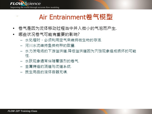
3.Meshing& Geometry下设定孔隙材质相关参数 2.Physics下启动孔隙材质与选择材质模式类型
FLOW-3D® Training Class
Shallow Water浅水模式
• 适用:水深平均流体(Depth-Averaged Flow)
• 变密度模式在单一流体方程以外多考虑密度传输方程式,这样就可以仿真不同密度 流体之间的传输扩散行为 (例如水和油).
no variable density requiresheattransfer orscalars requiresheat transfer full transport equation:
FLOW-3D® Training Class
Turbulence紊流模型
• 紊流模式是紊流黏滞性假说来表现紊流动量的生 成与消減:紊流动量的变化是剪力造成的局部流体 黏滞力改变的影响 • 经验模式 (Prandtl and 1-equation model)完全 使用现有与过去的速度场计算紊流能量 • 二式模式 (k-e model and RNG model)另外考 虑消散率 • 大涡仿真模型(Large Eddy simulation model) 模拟流场中的大涡旋,基于局部剪应力计算紊流 黏滞力 –准确不过耗时.
• Bulking: 必须同时开启 Density Evaluation 密度变化模型/solve transport equation 选項.由于较大的空气含量,模型将会计算流体体积中卷气的增加量 ( 也代表网格中流体密度变小).这个模型可能也需要同时开启 Drift Flux 物理模型 以仿真空气因为浮力效应而离开流体的现象.
全球气候模式中的云微物理参数化方案优化
全球气候模式中的云微物理参数化方案优化在全球气候模式中,云微物理参数化方案是非常重要的因素之一。
云微物理参数化方案是一种近似描述云微观结构和云微观物理过程的方法,它影响着模式对云和降水的模拟结果。
优化云微物理参数化方案能够提高模式对云的模拟准确性,从而提高模式对气候系统的预测能力。
云微物理参数化方案的优化可以从多个方面入手。
首先,需要考虑云粒子的尺寸和分布。
云粒子的尺寸和分布决定了云的光学性质和降水的形态。
通过对云粒子尺寸分布的观测和研究,可以优化参数化方案中的云粒子相关参数,提高对云的模拟精度。
其次,云微物理参数化方案还需考虑云的垂直结构和水平分布。
云的垂直结构对于气候系统中的物质交换和能量传递非常重要。
通过观测和模拟,可以获得云的垂直分布信息,从而优化模式中的云微物理参数化方案,提高对云垂直结构的模拟能力。
此外,云的水平分布对于气候系统中的辐射和降水分布具有重要影响。
观测和研究云水平分布的空间特征和时间变化,可以为云微物理参数化方案的优化提供重要的参考。
通过合理地处理云的分布特征,可以提高模式对云辐射效应和降水模拟的准确性。
在云微物理参数化方案的优化过程中,还需考虑云的多尺度特性和复杂性。
云系统具有多尺度的结构和复杂的演变过程,仅仅依靠单一的参数化方案难以准确模拟。
因此,引入多尺度模拟和耦合方法是优化云微物理参数化方案的有效途径。
多尺度模拟技术可以将较小尺度的云特征引入到参数化方案中,提高对大尺度云系统的模拟能力。
耦合方法则可以将模式中的不同组分相互联系,实现更综合的模拟。
最后,为了进一步优化云微物理参数化方案,还需加强参数化方案中的物理过程理论研究和实测数据的对比分析。
通过对参数化方案中的物理过程进行深入研究,可以更好地理解云微观结构和云微观物理过程的本质,从而改进模式对云的描述。
同时,将观测数据与模拟结果进行对比分析,可以验证参数化方案的可靠性和准确性。
总之,全球气候模式中的云微物理参数化方案的优化对于提高模式对云的模拟准确性和气候系统的预测能力至关重要。
用于处理器核心内的细粒度低时延解压缩的应用编程接口[发明专利]
![用于处理器核心内的细粒度低时延解压缩的应用编程接口[发明专利]](https://img.taocdn.com/s3/m/2f2eb7dfc9d376eeaeaad1f34693daef5ef7136c.png)
专利名称:用于处理器核心内的细粒度低时延解压缩的应用编程接口
专利类型:发明专利
发明人:贾耶什·高尔,阿达什·乔汉,维诺达·戈帕尔,韦德维亚斯·山博格,斯雷尼瓦斯·苏布拉莫尼,瓦伊迪·费加利
申请号:CN202111387205.6
申请日:20211122
公开号:CN114661359A
公开日:
20220624
专利内容由知识产权出版社提供
摘要:本公开涉及用于处理器核心内的细粒度低时延解压缩的应用编程接口。
描述了涉及用于处理器核心内的细粒度低时延解压缩的应用编程接口API的方法和装置。
在实施例中,解压缩应用编程接口API接收数据对象的输入句柄。
该数据对象包括压缩的数据和元数据。
解压缩引擎DE电路对压缩数据进行解压缩,以生成未压缩的数据。
DE电路响应于解压缩API对解压缩指令的调用,而对压缩数据进行解压缩。
元数据包括:第一操作对象,用于指示压缩数据的位置;第二操作对象,用于指示压缩数据的大小;第三操作对象,用于指示DE电路的解压缩数据要被存储到的位置;以及第四操作对象,用于指示解压缩数据的大小。
还公开并且要求保护了其他实施例。
申请人:英特尔公司
地址:美国加利福尼亚州
国籍:US
代理机构:北京东方亿思知识产权代理有限责任公司
代理人:陈蒙
更多信息请下载全文后查看。
面向二进制代码的细粒度软件多样化方法
面向二进制代码的细粒度软件多样化方法何本伟;郭云飞;梁浩;王庆丰【期刊名称】《计算机工程》【年(卷),期】2024(50)1【摘要】现有软件多样化方法大多需要源代码,基于编译器生成变体二进制,而对二进制代码直接进行转换时由于缺乏调试信息导致难以正确逆向,且易造成高额的性能开销。
为此,提出一种面向二进制代码的细粒度软件多样化方法。
通过静态二进制重写技术以函数块为单位进行重排序,随机化函数在代码段中的原始位置,同时使程序的内存片段gadgets位置发生改变,使得攻击者对程序的先验知识失效,以防御大规模代码重用攻击。
为了进一步提高攻击者破解难度,对基本块内的指令进行依赖性分析,实现基本块内指令随机化,同时使得随机化后基本块的原始语义不变。
性能测试结果表明,函数重排序对gadgets存活率的影响大于基本块内指令重排序,两者同时使用时程序的gadgets平均存活率为5.71%;模糊哈希算法Tlsh比较结果显示,该方法能够有效躲避同源性检测;使用工具Bindiff进行测试的结果表明,多样化后基本块内指令重排序的异构度大于函数重排序,且在基准测试集SPECCPU2006上函数重排序和指令重排序同时使用时平均运行开销仅为3.1%,具有良好的实用性。
【总页数】7页(P138-144)【作者】何本伟;郭云飞;梁浩;王庆丰【作者单位】信息工程大学信息技术研究所【正文语种】中文【中图分类】TP391【相关文献】1.面向细粒度源代码变更的缺陷预测方法∗2.二进制代码块:面向二进制程序的细粒度控制流完整性校验方法3.一种面向二进制的细粒度控制流完整性方法4.面向代码审查的细粒度代码变更溯源方法因版权原因,仅展示原文概要,查看原文内容请购买。
最差性能最优的稳健波束形成算法
最差性能最优的稳健波束形成算法刘聪锋;廖桂生【摘要】基于最差性能最优的稳健波束形成算法可以等价转换成加载样本矩阵求逆(LSMI)算法,提出了一种新的求解方法,准确地计算出Lagrange乘数,给出了LSMI算法中的最优加载量,解决了对角加载技术中加载量估计难题.理论分析和计算机仿真表明,具有最优负加载的LSMI波束形成算法具有最优的性能改善,模约束参数选取得越大,性能改善越接近于最优.【期刊名称】《西安电子科技大学学报(自然科学版)》【年(卷),期】2010(037)001【总页数】8页(P1-7,17)【关键词】自适应波束形成;导向矢量失配;最差性能最优;负对角加载【作者】刘聪锋;廖桂生【作者单位】西安电子科技大学雷达信号处理重点实验室,陕西,西安,710071;西安电子科技大学雷达信号处理重点实验室,陕西,西安,710071【正文语种】中文【中图分类】TN911自适应波束形成技术广泛应用于雷达、声纳、地震学、麦克风阵列语音处理以及无线通信中.当假定的信号导向矢量和其真实值之间存在失配时,自适应波束形成器的性能将会明显地下降.因此,稳健性就成为自适应阵列处理的必须要求.传统的稳健自适应波束形成算法,如用于改善信号观察方向失配的线性约束最小方差(LCMV)波束形成算法,不能改善其他类型的失配,如不准确的阵列校准、波前失真以及信源扩展等.用于改善一般失配的基于特征空间(ESB)的稳健算法[1]和协方差矩阵消锥(CMT)方法[2],ESB算法受限于信噪比和信号加干扰子空间维数的约束,尽管CM T算法对于非平稳干扰具有良好的稳健性,但是不能克服有用信号阵列响应的失配.还有常用的对角加载技术[3],尽管它能够改善对于任意信号阵列响应失配的稳健性,但是它的主要缺点是很难找到一种容易且可靠的方法来计算最优的加载电平. 几乎所有的传统稳健波束形成算法都是针对特殊的失配问题.近几年提出了在理论上比较严格的稳健波束形成算法[4-15],其主要思想是定义了所谓的不确定集和使最差性能最优,最后也归类到利用对角加载技术进行性能改善.尽管有些算法给出了具体的加载量计算方法,但是性能改善并不明显,而其他算法只是给出了近似的求解方法.其中S.A.Vorobyov等人基于导向矢量失配的最差性能最优提出了一种稳健的自适应波束形成算法[9],但是没有给出该最优化问题的准确解决方法,只是利用凸的二阶锥(SOC)规划实现了该问题的近似求解.笔者针对基于最差性能最优的稳健波束形成算法,通过将其等价转换成容易求解的加载样本矩阵求逆(LSMI)算法后,提出了一种新的求解方法,得到了准确的Lagrange乘数,从而给出了LSMI算法中最优的加载量,解决了对角加载技术中加载量估计的难题.重要的是通过分析发现,具有最优负加载的LSMI算法具有最优的性能改善.最后的仿真分析验证了该算法的正确性和有效性,并发现模约束参数选择得越大,性能的改善越接近于最优.1 基于最差性能最优的稳健波束形成算法在实际的波束形成应用中,假定的信号导向矢量和其实际值之间或多或少存在一定的失配(误差),但是导向矢量误差e的模可以通过某些已知(人为指定)的常数ε>0进行约束:当导向矢量误差的模由上面的约束进行限制时,实际的信号导向矢量c将属于下面的集合:其中a表示估计的(假设的)信号导向矢量.为了获得良好的稳健性,应该对所有属于集合A(ε)的导向矢量强加一个约束,即阵列响应的绝对值应该不小于1,故有因此,稳健的自适应波束形成算法[9]可以表示为其中R^为样本协方差矩阵.该波束形成算法中的约束条件保证了在最差条件下来维持无失真响应.由于该问题是一个半无限非凸的二次问题.为了求解,必须首先将半无限非凸约束转化为对应于最差条件下的单一约束.根据A(ε)的定义,并应用三角不等式、Cauchy-Schwarz不等式以及不等式关系≤ε,可以将上式转化为如下所示的具有单一非线性约束的二次最小化问题:然而该式的非线性约束仍然是非凸的,但是通过观察目标函数可以发现,当加权矢量w进行任意的相位旋转时,该目标函数保持不变.因此,上式可以被等价转化为因此,相对于原始的波束形成问题,该波束形成算法具有更加简单的数学表示,而且是凸的.尽管波束形成的最优化问题得到了简化,但是仍然不能获得紧凑的解.文献[9]证明了上式等价于加载样本矩阵求逆(LSMI)波束形成算法.即该最优化问题可以简化描述为该最优化问题可以利用Lagrange乘数方法进行求解.而且其解可以通过最小化如下所示的函数获得,即:其中λ为Lagrange乘数.对H(w,λ)求相对于参数w的梯度,并令梯度函数等于零,可得最优的加权矢量:对上式应用矩阵求逆定理,可得最优加权矢量的表达式为:从该式可以看出,该稳健的波束形成算法属于对角加载类处理方法,即加载样本矩阵求逆(LSMI)波束形成算法.由于很难利用该式求出准确的加权矢量表达式,文献[9]利用凸的二阶锥(SOC)规划对最优化问题(6)进行了求解,并给出了近似的求解方法,Jisung Oh等人也没有直接求解该问题,也是给出了一个近似的求解方法[10]. 对于具有对角加载形式的稳健波束形成算法,性能的改善取决于加载电平的选取,当加载电平为最优值时,性能的改善将是最优的.但是对于其他取值,性能的改善将会很小,甚至变差.因此,如何求解最优的加载电平是实现稳健波束形成算法的关键.如果能够根据约束条件准确地求解式(10)中的Lagrange乘数λ,则可以获得准确的加载量.下面给出Lagrange乘数的准确求解方法.2 Lagrange乘数λ的准确求解下面针对LSMI波束形成算法,利用加权矢量的表达式和约束条件对Lagrange乘数进行精确的求解.2.1 求解方程的获得利用最优加权矢量的表达式,可得:令求函数x(λ)关于参数λ的导数,即因此,wHa和wHw可以重新如下将式(15)和式(16)代入式(7)中的等式约束条件,并经过简单数学处理,可以得到关于参数λ的微分方程:求解该微分方程,可以得到函数x(λ)的解:其中C为任意常数.因此,将式(13)代入上式,可得关于Lagrange乘数λ的方程为了方便求解该方程,首先对样本协方差矩阵进行特征分解(EVD),即其中λi(i=1,2,…,N)和ui(i=1,2,…,N)分别为R^的特征值和特征矢量,N为阵列的自由度.因此,可得加载样本协方差矩阵的求逆结果:所以,式(19)可以重新表示为显然,当ε≥0时,上式左边表达式为ε的减函数,即当C大于零,且ε=ε1时的解如果等于无常数C方程中ε=ε2时的解,则必满足ε2<ε1,反之亦然.因此常数C存在时方程的求解等价与无常数C时方程的求解,只是对应于不同的ε.故常数C的存在与否,并不影响方程的求解,只是对于相同的ε,不同的C对应于不同的解.后面将会详细分析,常数C的选取并不影响最优加载电平的求解.为了分析和求解方便,令任意常数C=0,即可获得求解最优Lagrange乘数λ的方程为如果可以找到满足上式的λ,则为满足式(7)中等式约束的最优Lagrange乘数λ.下面分析最优 Lagrange乘数λ的存在性和惟一性.2.2 解的存在性讨论为了讨论最优Lagrange乘数λ存在性,以及利用上式求解λ时的可能取值范围,假设特征值(特征矢量)按照如下所示的降序进行排列,即对式(23)左边的表达式进行放大和缩小,可以得到为了分析的方便,令注意到y1(λ)和y2(λ)分别为λ∈R的单调减函数,而且y1(λ)也是其表达式分母中的每一个变量的单调减函数.因此,可得通过求解该不等式组,并判断是否满足方程式(23),可得Lagrange乘数λ的取值范围和解的存在性如下:①如果ε2/η<1,则存在惟一的解λ>0,并且λ∈ λN/(η-ε2),λ1/(η-ε2)满足方程式(23).②如果ε2/η=1,显然,只有当λ→∞时,不仅满足式(29),而且还满足方程式(23).③如果 1 <ε2/η≤λ1/(λ1-λN),则存在惟一的解λ<0,并且λ∈ [-λ1/(ε2-η),-λN/(ε2-η)] 满足方程式(23).④如果ε2/η≥λ1/(λ1-λN),则存在惟一的解λ<0,并且λ∈ [-λ1/(ε2-η),-λ1/ε2)] 满足方程式(23).从上面的求解结果可以得出结论:(1)导向矢量的误差约束参数ε决定最优Lagrange乘数的取值范围和求解结果;(2)如果导向矢量的误差约束参数ε比较小,则最优Lagrange乘数为正,因而最优的加载电平也为正,但是对于较大值,最优Lagrange乘数为负,因而最优的加载电平也将为负;(3)对于ε2/η=1时,最优λ→∞特殊情况,也可以通过①和③的渐进特性获得.2.3 最优负加载和约束参数选取的讨论由于ε为人为指定的误差约束参数,故理论上可以取大于零的所有值.然而对于小的模约束参数,导向矢量误差不在该约束条件之内,或者相对而言约束条件比较弱.但是对于较大的约束参数,导向矢量误差满足约束条件,即约束是起作用的.因此结合上面的求解分析,对于LSMI波束形成算法,约束参数应取尽可能大的数值,因而最优的加载电平应为负值,即为负加载.通过上面的分析可得,当ε→∞时,最优加载电平λ ε2→-λ1(但是λ ε2<-λ1),即当约束参数逐渐增大时,最优加载电平的取值趋于一常数,即最优加载电平不随约束参数的变化而变化.这是因为接收数据中的误差是一定的,故最优的加载电平是惟一的.而约束参数是人为指定的参数,故最优加载电平不应随约束参数的变化而变化.因此可以断定以上分析和求解是正确的.前面讨论了常数C的存在并不影响方程的求解,故为了分析和求解的方便,令任意常数C=0,而且也得出了最优加载电平不随约束参数的变化而变化.其实任意常数C的取值并不影响最优加载电平的求解,而且可以利用式(22)进行简单的分析 .由于当ε→∞时 ,最优加载电平λ ε2 →-λ1且满足λ ε2 <-λ1,故有λ ε2+λi<0(i=1,2,…,N),而且此时式(22)的左边为ε的减函数.因此当C取大于零的常数值时,为了求得与C=0时相同的最优加载电平,相当于约束参数ε取较小的数值.反之,当C取小于零的常数值时,相当于约束参数ε取较大的数值.由于当ε→∞时,即可获得最优加载电平,故任意常数C的取值并不影响最优加载电平求解.然而对于一般的对角加载技术以及其他参考文献所讨论的对角加载,通常讨论的是正加载,尤其是文献[9]在求解时直接限制Lagrange乘数λ为正数.但是通过精确的求解和分析,对于LSMI波束形成算法,最优的加载电平为负加载.对于应用负加载的稳健波束形成算法,最优加载电平必须被准确地计算,否则加载协方差矩阵将变成不可逆.从上面的讨论结果,也可以得到选择导向矢量误差约束参数的方法.由于信号导向矢量误差包含在参数η中,因而在实际应用时,约束参数的选择应根据上面求解过程中的应用条件进行.因此,模约束参数应该选择尽可能大的数值,使约束起作用.而且当模约束条件远远强于实际的导向矢量误差时,性能的改善更优,同时也可以大大降低计算最优Lagrange乘数λ的计算量.即可以选择很大的ε,将-λ1/(ε2-η)作为最优λ即可获得最优的性能改善,而且此时还可以避免大量的搜索运算.3 仿真分析为了验证LSMI算法的稳健性,以及求解的正确性,进行如下的仿真分析.假设阵列为理想均匀线阵,阵元数M=10,阵元间距为半波长.为了获得导向矢量误差,假设信号的位置方向为0°,而假定的信号方向为5°,即存在5°的信号方向失配.导向矢量误差等于实际的信号导向矢量与假定的信号导向矢量之差.仿真中分别分析了LSMI算法的稳健性、对角加载电平和模约束参数对波束形成算法的影响.为了分析如何选择模约束参数,仿真中的导向矢量误差约束参数值是用假定信号导向矢量模的倍数进行计算的.3.1 波束形成算法的稳健性SMI波束形成算法的方向图如图1所示.由于信号指向失配的存在,即存在导向矢量误差,SMI的主瓣指向偏离了真实的信号方向.当模约束参数选择为假定信号导向矢量模值的5倍时,通过最优(负)加载,LSMI指向了实际的信号方向,且具有较低的旁瓣电平.因此,有效的加载技术能够很好地克服导向矢量误差,并且改善波束形成算法的指向性能.图1 SMI波束形成算法的方向图图2 SMI的SNR相对于样本数量的变化SMI的输出信噪比(SNR)相对于样本数量的变化如图2所示.其中LSMI的SNR相对于SMI要高很多(大约有5dB),这是由于LSMI的方向图准确地指向了信号的真实方向,而SMI的指向具有一定的偏差.小样本数量条件下,LSMI的SNR起伏较大是由模约束参数的选择引起的,其中模约束参数始终选择为假定信号导向矢量模值的5倍.但是协方差矩阵不同,因而最优Lagrange乘数λ的求解结果也就不同,进而影响输出的SNR,但是随着样本数量的增加,SNR曲线的起伏明显降低,并在一常数值(0.5dB)附近波动.SMI的输出信噪比(SNR)相对于信号方向失配的变化如图3所示.当失配角度在[-7°,7°]的范围之内变化时,相对于SMI和理想情况下的SMI(图3中标记为Ideal-SMI,其中所用的导向矢量为其实际值),LSMI具有较高的SNR.LSMI的SNR高于Ideal-SMI是由LSMI具有更低的旁瓣电平引起的.而且在仿真中,LSMI的方向图也准确地指向了实际的信号方向.因此,LSMI波束形成算法在信号方向失配情况下具有良好的稳健性.图3 SMI的输出SNR相对于方向失配的变化图4 LSMI的SNR相对于 Lagrange乘数λ的变化3.2 加载电平对波束形成算法的影响对于LSMI波束形成算法,关键是求解最优加载电平,也就是必须准确地求解Lagrange乘数λ.为了分析对角加载对SMI的影响以及求解的正确性,进行如下的仿真分析.LSMI的输出信噪比(SNR)相对于Lagrange乘数λ的变化如图4所示,其中模约束参数选择为假定信号导向矢量模值的5倍.显然,负加载的SNR要稍微高于正加载的SNR,而且在最优的负加载时,即最优的Lagrange乘数λ等于-0.0170时,SNR 将达到最大.因此,对于LSMI波束形成算法,最优加载电平的求解是获得最优性能改善的关键.所以,当模约束参数给定时,Lagrange乘数λ的选择对LSMI方向图具有较大的影响,而且决定着性能的改善,并且最优的负加载具有最优的性能改善.3.3 模约束参数对波束形成算法的影响对于LSMI波束形成算法,有两个关键问题,一个是最优Lagrange乘数λ的计算,另一个就是模约束参数的选择.为了验证求解的正确性和分析如何选择模约束参数,进行如下的仿真分析.图5 模约束参数对最优λ及其取值范围的影响图6 模约束参数对最优加载电平的影响当模约束参数在假定导向矢量模的0倍到15倍之间变化时,最优Lagrange乘数λ及其取值范围相对于模约束参数的变化如图5所示,而最优加载电平的变化如图6所示.与理论分析的相一致,当模约束参数较小时为正的对角加载,而当模约束参数较大时为负的对角加载.当模约束参数逐渐增加时,最优加载电平趋于恒定,即当模约束参数大于一定数值时,通过增加模约束参数,对LSMI的性能改善不大.这是因为对于已知的接收数据,误差是一定的,因此最优的加载电平也是一定的.由于最优加载电平为λ ε2,因此对于一定的加载电平,最优Lagrange乘数与模约束参数成反比,即当模约束参数增大时,最优Lagrange乘数将变小,这与图5中的曲线相一致.从上面的理论分析和仿真结果也可以得到模约束参数的经验选取方法.即在实际应用中,模约束参数应该选择尽可能大的数值.当模约束参数在假定导向矢量模的0倍到15倍之间变化时,LSMI的输出信噪比(SNR)相对于模约束参数的变化如图7所示.随着模约束参数的增加,SNR逐渐升高.但是在较小的模约束参数取值区间,SNR升高的比较迅速,当模约束参数大于一定数值后,SNR增加的比较缓慢,而且趋近于一恒定的常数.这是因为随着约束参数的增加,波束逐渐指向信号的真实方向,而且当模约束参数大于一定的数值后,波束形成算法的指向性能将会趋于恒定,这与图6的分析结果相一致.因此,结合前面的分析结果,在实际应用中,当模约束参数选择中等大小数值时即可获得接近最优的性能改善. 图7 模约束参数对LSM I的SNR的影响因此,模约束参数的选择对LSMI方向图具有较大的影响,而且决定着性能的改善. 综上所述,可以得出结论:(1)笔者所提出的求解方法是正确的和有效的.(2)有效的加载可以改善SMI波束形成算法的指向性能,即最优负加载具有最优的性能改善.(3)模约束参数的选择决定着性能的改善,通过仿真试验可知,当模约束参数选择为中等大小的数值时,例如对于本文所用的场景,当模约束参数大于假定信号导向矢量模值的5倍时,LSMI的性能即可接近最优.4 结论对于任意未知信号导向矢量失配存在时的稳健自适应波束形成算法可以等价转化为加载样本矩阵求逆(LSMI)算法.针对LSMI波束形成算法,笔者提出了一种新的求解方法,获得了Lagrange乘数的准确求解方法,解决了对角加载技术中加载量估计的难题.而且得出具有最优负加载的LSMI波束形成算法具有最优的性能改善.通过理论分析和仿真试验,证明模约束参数选择得越大,性能的改善越接近于最优.参考文献:[1] Feldman D D,Griffiths L J.A Projection Approach to Robust Adaptive Beamforming[J].IEEE Trans on Signal Processing,1994,42(4):867-876. [2] Guerci J R.Theory and Application of Covariance M atrix Tapers for Robust Adaptive Beamforming[J].IEEE Trans on SignalProcessing,1999,47(4):997-985.[3] Carlson B D.Covariance Matrix Estimation Errors and Diagonal Loading in Adaptive Arrays[J].IEEE T rans on Aerosp Electron Syst,1988,24(7):397-401.[4] Tian Z,Bell K L,Van Trees H L.A Recursive Least Squares Implementation for LCMP Beamforming under Quadratic Constraint[J].IEEE T rans on Signal Processing,2001,49(6):1138-1145.[5] Elnashar A,Elnoubi S M,El-Mikati H A.Further Study on Robust Adaptive Beamforming With Optimum Diagonal Loading[J].IEEE T rans on Antennas Propagation,2006,54(12):3647-3658.[6] Li Jian,Stotica P,Wang Zhisong.On Robust Capon Beamformer and Diagonal Loading[J].IEEE Trans on Signal Processing,2003,51(7):1702-1715.[7] Li Jian,Stotica P,Wang Zhisong.Doubly Constrained Robust Capon Beamformer[J].IEEE Trans on Signal Processing,2004,52(9):2407-2423. [8] Shahbazpanahi S,Gershman A B,Luo Zhiquan,et al.Robust Adaptive Beamforming for General-rank Signal M odels[J].IEEE Trans on Signal Processing,2003,51(9):2257-2269.[9] Vorobyov S A,Gershman A B,Luo Zhiquan.Robust Adaptive BeamformingUsingWorst-case Performance Optimization:a Solution to the Signal Mismatch Problem[J].IEEE Trans on SignalProcessing,2003,51(2):313-324.[10] Oh J S,Kim S J,Hsiung K L.A Computationally Efficient Method for Robust Minimum Variance Beamforming[C]//Vehicular Technology Conference 2005:Vol 2.Stockholm:IEEE,2005:1162-1165.[11] Robert G L,Stephen P B.Robust Minimum VarianceBeamforming[J].IEEE Trans on Signal Processing,2005,53(5):1684-1696.[12] Cesar C G,Ignacio S,Javier V,et al.Robust Array Beamforming with Sidelobe Control Using Support Vector Machines[J].IEEE Trans on Signal Processing,2007,55(2):574-585.[13] Mutapcic A,Kim S J,Boyd B.Beamforming with UncertainWeights[J].IEEE Signal Processing Letter,2007,14(5):348-351.[14] Chen C Y,Vaidyanathan P P.Quadratically Constrained Beamforming Robust Against Direction-of-Arrival Mismatch[J].IEEE Trans on Signal Processing,2007,55(8):4139-4150.[15] Eldar Y C,Nehorai A,La Rosa P S.A Competitive Mean-squared Error Approach to Beamforming[J].IEEE Trans on SignalProcessing,2007,55(11):5143-5154.。
一种基于递归系统卷积码校验重量下限的匹配交织器设计方法
一种基于递归系统卷积码校验重量下限的匹配交织器设计方法肖勇;张雄伟;邹霞;崔姚
【期刊名称】《信号处理》
【年(卷),期】2009(025)009
【摘要】针对短帧Turbo码中交织器优化设计问题,提出了一种基于递归系统卷积码(RSC)校验重量下限的匹配交织器设计方法.文中重新分析了Turbo码中"局部坏点"具体形式,然后提出并证明了一种估计RSC分量码校验序列重量下限的方法,并将其应用于交织器映射方式优选时局部坏点对应Turbo码字重量下限估计,只有能够保证所有局部坏点对应码字重量的交织方法才被认为合法.仿真表明,与几种现有交织器设计方法相比,本文提出的匹配交织器设计方法性能更加优良,可以有效改善Turbo码的误比特性能.
【总页数】5页(P1366-1370)
【作者】肖勇;张雄伟;邹霞;崔姚
【作者单位】解放军理工大学通信工程学院,南京,210007;解放军理工大学通信工程学院,南京,210007;解放军理工大学通信工程学院,南京,210007;通信指挥学院,武汉,430000
【正文语种】中文
【中图分类】TN911
【相关文献】
1.(n,1,m)递归系统卷积码的盲识别 [J], 张立民;刘杰;钟兆根
2.基于递归神经网络的卷积码解码器的研究 [J], 林国华;殷奎喜
3.一种新型Turbo码交织器设计方法 [J], 王令成;林中
4.基于卷积码的Turbo码交织器的设计 [J], 吴克颖;李晖;王育民
5.长约束非递归系统卷积码的盲识别 [J], 王甲峰; 胡茂海; 蒋鸿宇; 漆钢
因版权原因,仅展示原文概要,查看原文内容请购买。
一种用于截幅音频修复中的自适应一致迭代硬阈值算法
一种用于截幅音频修复中的自适应一致迭代硬阈值算法邹霞;吴彭龙;孙蒙;张星昱【摘要】一致迭代硬阈值(CIHT)算法在处理音频截幅失真中具有较好的性能.但是,在截幅程度较大时音频截幅修复的性能会下降.因此,该文提出一种基于自适应门限的改进算法.该算法自动估计音频信号截幅程度,根据估计的截幅程度信息,自适应调整算法中的截幅程度因子.与近年来提出的CIHT算法和一致字典学习算法(CDL)相比,该文所提算法能更好地重建音频信号,特别在音频信号截幅失真严重的情况.该算法的运算复杂度与CIHT相近,与CDL相比,拥有更快的运行速度,有利于实时实现.【期刊名称】《电子与信息学报》【年(卷),期】2019(041)004【总页数】7页(P925-931)【关键词】音频信号处理;截幅失真;自适应门限;一致迭代硬阈值【作者】邹霞;吴彭龙;孙蒙;张星昱【作者单位】陆军工程大学指挥控制工程学院南京 210007;陆军工程大学指挥控制工程学院南京 210007;陆军工程大学指挥控制工程学院南京 210007;陆军工程大学指挥控制工程学院南京 210007【正文语种】中文【中图分类】TN912.31 引言现实生活中,由于录音设备和环境的影响,音频信号会出现不同程度的失真。
其中,截幅失真是一种较为常见的失真类型。
截幅的发生,会给信号造成刺耳的噪声。
如果截幅程度过大,会严重影响音频的听觉质量,且不利于音频信号的进一步处理。
如何根据前后未被截幅的信号来恢复被截幅的信号是一项有意义的研究。
目前针对截幅信号修复的方法包括:自回归模型[1] 、受限带宽模型[2] 和贝叶斯估计[3]等。
近年来,基于稀疏表示的信号修复技术引起了广泛关注。
这类方法的基本思想在于音频信号可以用字典进行稀疏表示。
基于音频信号的稀疏表示思想,文献[4]通过舍弃被截幅的样本点,将其描述为未被截幅样本点上的稀疏分解问题。
在重建音频信号过程中,使用额外的有用信息有助于改善重建信号的质量。
压缩感知平滑LO范数算法的改进的开题报告
压缩感知平滑LO范数算法的改进的开题报告一、研究背景压缩感知是一种基于稀疏性的信号采样和重构技术,可以在保证一定的重构质量的情况下,对信号进行高效的压缩采样。
平滑LO范数是一个可以用于对信号的平滑区域进行加权惩罚,促进平滑信号重构的范数选择。
压缩感知平滑LO范数算法是将两种技术结合使用,用于信号重构,但是在实际应用中仍然存在一些问题需要解决。
二、研究目的本研究旨在对压缩感知平滑LO范数算法进行改进,提高其对平滑信号的重构质量,并且在不增加计算复杂度的基础上,提高算法的收敛速度和稳定性。
同时,本研究还将通过实验验证改进算法的效果和优势。
三、研究内容1. 对压缩感知平滑LO范数算法进行分析和研究,发现存在的问题和不足之处。
2. 提出改进算法,包括但不限于引入新的惩罚项、优化求解方法、修改参数等。
3. 对改进算法进行实现和仿真实验,对比评估改进算法和原算法的重构效果,以及收敛速度和稳定性等性能指标。
四、研究意义1. 改进压缩感知平滑LO范数算法,可以提高信号重构的效果和质量,有助于其在实际应用中的推广和应用。
2. 改进算法的实现过程中,将综合运用信号处理、计算优化、数学建模和实验验证等多种方法和技术,有利于研究人员的综合素质提升。
3. 改进算法的研究对压缩感知等相关领域的研究和应用具有一定的推动作用,有助于提高相关技术的应用价值和影响力。
五、研究方法与实验方案1. 研究方法:本研究将综合应用数学建模、算法设计、计算优化等多种方法,对压缩感知平滑LO范数算法进行研究和改进。
具体而言,将结合算法分析、数学模型设计、算法实现、实验验证等环节,在理论和实际层面上,全面探索和改善压缩感知平滑LO范数算法的性质和效果。
2. 实验方案:在实验过程中,将利用MATLAB等软件实现算法的具体过程,并通过选用不同的数据集和评价指标,进行重构效果、算法收敛速度和稳定性等方面的对比实验,评估算法的性能表现。
六、进度安排1. 第一周:进行相关文献调研,研究压缩感知平滑LO范数算法的基本思路和实现过程,并对其存在的问题和不足之处进行分析。
- 1、下载文档前请自行甄别文档内容的完整性,平台不提供额外的编辑、内容补充、找答案等附加服务。
- 2、"仅部分预览"的文档,不可在线预览部分如存在完整性等问题,可反馈申请退款(可完整预览的文档不适用该条件!)。
- 3、如文档侵犯您的权益,请联系客服反馈,我们会尽快为您处理(人工客服工作时间:9:00-18:30)。
a r X i v :0806.2827v 1 [h e p -p h ] 17 J u n 2008Dynamically generated heavy scalar fields in the Standard Model of Electroweak Interactions Bing An Li Department of Physics and Astronomy,University of Kentucky Lexington,KY 40506,USA Abstract It is shown that the gauge fixings of the Z and the W fields and three scalars are via nonconserved axial-vector and charged vector currents of massive fermions dynamically generated by fermion masses in the SM of EW interactions.The top quark massprovides enough strength for this chiral symmetry breaking.The masses of the three scalars are determined to be about 1014GeV.These scalars have negative probability.They are the nonperturbative solutions of the SM.A new perturbation theory with dynamically generated and fixed gauge fixings is constructed.The Faddeev-Popov procedure is not invoked.1In the SM of electroweak interactions(EW)[1]there are spontaneous symmetry breaking, Higgs,and Faddeev-Popov procedure.The theory is successful in many aspects.Other theoretical approaches:Supersymmetry models,Technichcolor,little Higgs etc.,have been proposed to modify the SM.In Ref.[2]the effect of top quark condensate has been studied.A new mechanism of chiral symmetry breaking has been found in Ref.[3]:the masses and the gaugefixings of the Z and the Wfields and three scalars are via nonconserved axial-vector and charged vector currents of fermions dynamically generated by fermion masses in EW theory.The mass of the top quark provides enough strength for chiral symmetry breaking. In this paper this new mechanism is applied to the SM of EW theory.It is shown that the scalars are the nonperturbative solutions of the SM.A brief review of previous study of the new mechanism is presentedfirst.This mechanism is inspired by Weinberg’s second sum rule[4],m2a=2m2ρ.a1andρmesons are chiral partners and they are degenerate under chiral symmetry.Obviously,Weinberg’s second sum rule implicates a new mechanism of chiral symmetry breaking.This new mech-anism has been studied by a chiralfield theory of pseudoscalar,vector,and axial-vector mesons[5].Based on current algebra and QCD the Lagrangian of this theory has been constructed as1L=¯ψ(x)(iγ·∂+γ·v+γ·aγ5−mu(x))ψ(x)+where u=e(iπ+iη0)γ5,m is the constituent quark mass which originates in quark condensate. The Lagrangian(1)has global SU(2)L×SU(2)R symmetry and the a1and theρfields have the same mass in Eq.(1).Integrating out the quarkfields,the Lagrangian of the mesons is derived,in which a1andρare nonabelian gaugefields.This theory is phenomenologically successful.The current quark masses can be added into Eq.(1).The masses of the pseu-doscalar mesons are obtained from explicit chiral symmetry breaking by the current quark masses.The masses of the vector mesons originate in dynamical chiral symmetry breaking and m2ρ=6m2is obtained.The mass relation between the a1and theρmesons is derived1(1−∆m2gµν}.(3)2In Ref.[5]Πµνhas been calculated to the fourth order in covariant derivatives.F2and∆m2 are the results of the nonconserved axial-vector current of the massive quark.The Weinberg’s3second sum rule is obtained from∆m2=m2ρ.The factor1−1of the aµ-field is constructed asL=−12m2aa2µand it is a Stueckelberg’s Lagrangian,whereξis a constant obtained from F2.The aµ-field has four independent components.Nonzero∂µaµleads to a spin-0field and gaugefixing. The new spin-0field is the nonperturbative solution of this theory.The mass of the spin-0field is determined by thefinite F2.The perturbation theory is constructed.The propagator of a-field with dynamically generated gaugefixing consists of two parts:spin-1and spin-zero. There is a minus sign in front of the spin-0part.Therefore,the spin-0field has negative probability.Similar mechanism is revealed[3a]from a theory of charged vectorfields which are coupled to nonconserved charged vector currents of massive fermions:the mass and the gaugefixing of the charged vectorfields and the charged scalarfields are via vacuum polarization dynamically generated from the fermion masses.The mass of the charged scalar is explicitly determined and it has negative probability.The axial-vector and the charged vector currents of the massive fermions exist in the EW theory.Therefore,the new mechanism of chiral symmetry breaking is already embedded in the theory.On the other hand,there is heavy top quark in the EW theory.The mass of the top quark provides enough strength for this chiral symmetry breaking.The masses of the intermediate bosons,the gaugefixings,and three scalars can via the new mechanism[5,3a]5be dynamically generated without invoking the spontaneous symmetry breaking and the Faddeev-Popov procedure in the EW theory.In Ref.[3a]an EW theory without spontaneous symmetry breaking,Higgs,and Faddeev-Popov procedure has been proposed.The Lagrangian of the(t,b)-quark generation is con-structed asL=−14BµνBµν+¯q L{iγ·∂+g2γ·B}q L+¯q R{iγ·∂+g′Y2g2m2t m2Z=12√well.The top quark plays dominant role.The theory predicts m2Wfermions are treated nonperturbatively dynamical generation of the gaugefixings and the three heavy scalarfields is inevitable.Therefore,the Feddeev-Popov procedure is no longer required.Why the fermion loops of the vacuum polarizations of the Z-and the W-field must be treated nonperturbatively?In the original SM all the interactions are treated perturbatively and after spontaneous symmetry breaking the Z and the W are massive spin-1fields and each has three degrees of freedoms.However,after nonperturbative treatment of the fermion loops of the vacuum polarization of the Z-and the W-field each of them gains the fourth component-a scalarfield,therefore,each has four independent degrees of freedoms.A properly constructed perturbation theory shouldn’t change the number of independent degrees of freedoms.It is known that in QED if all interactions are treated as perturbation, there are no positronium solutions.Only when the coulomb potential separated from the photon propagator of ee+→ee+scattering is treated nonperturbatively the solutions of positronium can be found.The scalarfields are nonperturbative solutions of the SM.There is another issue.For the vacuum polarizations of the Z-and the W-field at one-loop level besides the fermion loops there are other loop diagrams:loop diagrams of Higgs and intermediate bosons,loop diagrams of intermediate bosons only,and Higgs loop.The Higgs loop only contributes to the mass term of the intermediate boson.Except the fermion loops all other loop diagrams that affect F2require the propagators of intermediate bosons which can only be correctly defined after the fermion loops of the vacuum polarizations of the Z8and the Wfield are treated nonperturbatively.Based on these arguments the loop diagrams of fermions are treated nonperturbatively and all others are treated as perturbation.Because of nonconservation of the axial-vector currents of the massive fermions the am-plitude of the vacuum polarization of the Z-field by the fermions is expressed asΠZµν=12∆m2Z gµν,(5)F Z1(q2),F Z2(q2),and∆m2Z are presented in Ref.[3]at one-fermion loop level.Only the axial-vector currents contribute to F Z2(q2)and∆m2Z.In the limit m f→0F Z2(z)and∆m2Z go to zero.F Z1(z)is used to renormalize the Z-field and∆m2Z is absorbed via renormalization by m2Z.F Z2(z)isfinite.A constant is separated from F Z2(z)F Z2(q2)=ξZ+(q2−m2φ0)G Z2(q2),(6)where m2φ0is the mass of a new neutral spin-0field and G Z2is the radiative correction.The new free Lagrangian of the Z-field is constructed asL Z0=−12m2Z Z2µ.(7)Eq.(7)is Stueckelberg’s Lagrangian.∂µZµis an independent spin-0fieldφ0=−m Z2ξZφ0=0,Zµ=Z′µ+1Eq.(9)is dominated by the mass of the top quark and has a solution at very large q2.The mass of theφ0and the gaugefixing are determined to bemφ0=m t e m2z3¯g2+1=3.78×10¹⁴GeV,ξZ=−m2Zq2−m2Z {−gµν+(1+1q2−m2φ0}=1m2Z}−1q2−m2φ0.(11)There is a minus sign in front of the propagator of the scalarfield(11).The scalarfield has negative probability[3a].The W boson is coupled to both the charged axial-vector and vector currents of the massive fermions.These currents are not conserved.The vacuum polarization of the W-field by the massive fermions is expressed asΠWµν=F W1(q2)(qµqν−q2gµν)+2F W2(q2)qµqν+∆m2W gµν.(12) F W1,F W2,and∆m2W are presented in Ref.[3]at one-fermion loop level.F W1is used to renormalize W-field and the mass of the W boson is renormalized by∆m2W.Both the charged axial-vector and vector currents contribute to F W2and∆m2W which are proportional to the masses of the fermions.F W2isfinite and a constant is separated from itF W2=ξW+(q2−m2φW)G W2(q2),(13)10where G W2is the radiative correction and m2φWis the mass of the charged spin-0states.The free Lagrangian of W-field is defined asL W0=−1m2φW ∂µW±µ,∂2(∂µW±µ)−m2W3g2m2W2m2φW=−3.73×10⁻²⁵.(17)NegativeξW leads to positive mφW.The propagator of W-field with dynamically generated gaugefixing is derived from Eq.(14)∆Wµν=12ξW)qµqνq2−m2W{−gµν+qµqνm2WqµqνThe key functions F2Z,2W are calculated at one-fermion loop level.However,arguments for the existence of the scalarfield and the gaugefixing in a theory in which the current(the gaugefield is coupled to)is not conserved can be very general.Because of nonconservation of the current the vacuum polarization of the gaugefield should be written asΠµν(q)=f1(q2)(qµqν−q2gµν)+f2(q2)gµν.(19) Defining f2(q2)−f2(0)=−F2(q2)q2,Eq.(19)is rewritten asΠµν(q)=F1(q2)(qµqν−q2gµν)+F2(q2)qµqν+f2(0)gµν.(20) The function F2and the constant f2(0)are the results of the nonconserved current.f2(0)is the mass term of the gaugefield.After nonperturbative treatment of the vacuum polarization the gaugefixing and the scalarfield are revealed from F2.Because F2is unknown the mass of the scalarfield cannot be determined.The perturbation theory of the SM needs to be reconstructed.The free Lagrangian of Z and W are shown in Eqs.(7,14).AfterξZ,W are separated,the remaining parts of F2Z and F2W are still kept in the perturbation Lagrangian.Other part of the perturbation theory is the same as in the original perturbation theory of the SM.The differences between the new perturbation theory and the original one are:the gauge parameters of Eqs.(11,18) are dynamically generated andfixed(10,17),and there are no Faddeev-Popov ghosts.The Faddeev-Popov procedure used in the original SM is no longer invoked and there is no gauge12choosing in this new version of the perturbation e of the propagators(11,18)tocalculate the loop diagrams of physical processes is the direct test of the effects of the heavy scalars.For the tree diagrams at present level of energies the contribution of the scalar fields can be ignored.Therefore,the success of the SM at the tree level is kept.The free Lagrangian of the scalarfields is presented in Ref.[3a].The interactions between the scalar fields and others can be derived.As an example,the interaction between the charged scalarsand the photon is derived4ieL=References[1]S.L.Glashow,Nucl.Phys.B22,579(1961);S.Weinberg,Phys.Rev.Lett.19,1264(1967);A.Salam,Proc.of the8th Nobel Symposium,p.367,ed.By N.Svartholm,Almqvist andWilsell,Stockholm,1968.[2]Y.Nambu,in new Theories in Physics,proceedings of the XI international Symposium onElementary Particle Physics,Kazimierz,Poland,1988,edited by Z.Ajduk,S.Pokorski, and A.Trautman(World Scientific,Sigapore,1989);V.A.Miranski,M.Tanabashi,and K.Yamawaki,Mod.Phys.Lett.A4,1043(1989);Phys.Lett.B221177(1989);W.Bardeen,C.Hill and M.Lindner,Phys.Rev.D41,1647(1990); A.Blumhofer,R.Dawid andM.Lindner,Phys.Lett.B360,123(1995).[3]Bing An Li,(a)Intern.J.of Modern Phys.A17,3607(2002);Intern.J of ModernPhys.A192004;Modern Physics Letters,A172417(2002);Intern.J.of Modern Physics A16,4171(2001).[4]S.Weinberg,Phys.Rev.Lett.,18,507(1967).[5]Bing An Li,Phys.Rev.D52,5165-5183(1995);D52,5184-5193(1995).[6]It is worth to point out that the nonconserved axial-vector current mentioned hereis at the quark level.PCAC is related to the Lagrangian obtained by integrating14out the quarkfields,which is satisfied in this chiralfield theory of mesons: B.A.Li, Phys.Rev.D55,1436(1997).15。
