EZ5Z3中文资料
联想电脑 B5/B3系列3D套装配套软件iZ3D中文版安装说明

B5/B3系列3D套装配套软件iZ3D中文版安装说明联想服务官方网站:问题描述:B5/B3系列3D套装配套软件iZ3D如何使用?解决方案:一、软件安装1.如果您使用的是XP系统,请安装iZ3D之前先安装“dotnetfx.exe”,运行dotnetfx.exe,按照安装向导选择默认设置完成安装。
2.双击安装程序“iZ3DDriverSetup.Lenovo.1.11RC1(1.99.0156).exe”,出现图1的选择安装语言消息框。
图1 选择安装语言3.默认选择安装中文(简体)语言,点击确定,出现图2的许可协议消息框。
图2 许可协议4.选择接受协议,点击下一步,出现图3的消息框。
图3 信息5.点击下一步,出现图4的选择目标位置消息框。
图4 选择目标位置6.可以点击浏览按钮,更改程序的安装路径(安装路径按默认设置即可)。
点击下一步,出现图5的选择组件消息框。
图5 选择组件7.按照默认设置,点击下一步,出现图6的选择开始菜单文件夹消息框。
图6 选择开始菜单文件夹8.保持图6的默认设置,点击下一步,出现图7的准备安装消息框。
图7 准备安装9.点击安装,出现图8的DirectX 安装向导。
图8 DirectX 安装向导10.选择是,出现图9的欢迎使用DirectX 安装程序。
图9 欢迎使用DirectX 安装程序11.选择接受协议,并且点击下一步,出现图10的DirectX 安装程序。
图10 DirectX 安装程序12.点击下一步,DirectX 组件开始安装。
安装结束时出现图11的安装完成消息框。
图11 安装完成13.点击完成,DirectX 组件安装成功,之后重新返回到iZ3D的安装进程中,如图12所示。
图12 完成iZ3D安装二、软件设置iZ3D成功安装,之后出现iZ3D control center设置界面,如图13所示。
图13 iZ3D control center 的DirectX 选项卡(1)DirectX 选项卡立体状态:选择启用立体,游戏开始自动显示3D效果;选择用热键启用立体,游戏开始按“*”键显示3D效果;选择禁用立体,不显示3D效果。
ez5z3
VREF
VIN = 5V, IOUT = 500mA VIN = 5V, 10mA £ IOUT £ 1A
1.25
1.28 1.31
V
Load Regulati on Temperature C oeffi ci ent
REG(LOAD) TC
VIN = 5V, IOUT = 10mA to 1A VIN = 5V, IOUT = 500mA
q JC TA TJ TSTG TLEAD V ESD
°C °C °C °C kV
Electrical Characteristics
Unless specified: TA = 25°C. Values in bold apply over the full operating ambient temperature range.
SOT-223 TO-220
Pin 1 2 3 Function (-3.3) NC OUT IN TAB i s OUT Function (-AD J) ADJ OUT IN
Notes: (1) Only available in tape and reel packaging. A reel contains 2500 devices. (2) Only available in tube packaging. A tube contains 50 devices.
Symbol
EZ5Z3-3.3
EZ5Z3-ADJ
ã 2001 Semtech Corp.
3
EZ5Z3
POWER MANAGEMENT Outline Drawing - SOT-223
Land Pattern - SOT-223
3EZ56中文资料

MAXIMUM5RATINGS AND ELECTRICAL CHARACTERISTICS
Ratings at 25°C ambient temperature unless otherwise specified.
SYMBOLS
Pwak Pulse Power Dissipation on TA=50°C (Notes A) Derate above 70°C Peak Forward Surge Current 8.3ms single half sine-wave superimposed on rated load (JEDEC method) Operating and Storage Temperature Range
DATE : OCT.11.2002
PAGE . 1
元器件交易网
Part Number
V Z @ I ZT V
I ZT mA
M a x i m u m Ze n e r I m p e d a n c e Z ZT @ I ZT Z ZK @ I ZK Oh ms Oh ms I ZK mA
VALUE 3.0
UNITS Watts mW / °C Amps °C
PD IFSM TJ, TSTG
24.0 15 -55 to +150
NOTES: A.Mounted on 5.0mm2 (.013mm thick) land areas. B.Measured on8.3ms, and single half sine-wave or equivalent square wave ,duty cycle=4 pulses per minute maximum
元器件交易网
3EZ5.1D10中文资料
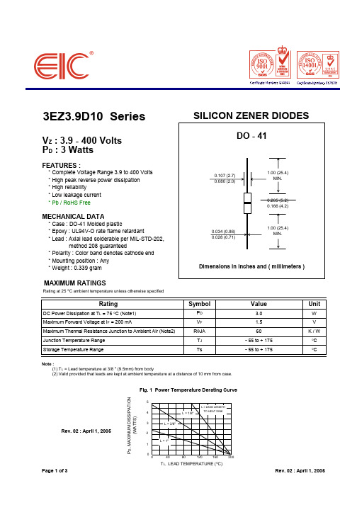
3EZ3.9D10 SeriesV Z : 3.9 - 400 Volts P D : 3 WattsFEATURES :* Complete Voltage Range 3.9 to 400 Volts* High peak reverse power dissipation* High reliability* Low leakage current * Pb / RoHS FreeMECHANICAL DATA* Case : DO-41 Molded plastic* Epoxy : UL94V-O rate flame retardant* Lead : Axial lead solderable per MIL-STD-202,method 208 guaranteed* Polarity : Color band denotes cathode end * Mounting position : Any * Weight : 0.339 gramMAXIMUM RATINGSRating at 25 °C ambient temperature unless otherwise specifiedRating SymbolValueUnitDC Power Dissipation at T L = 75 °C (Note1)P D 3.0W Maximum Forward Voltage at I F = 200 mAV F 1.5V Maximum Thermal Resistance Junction to Ambient Air (Note2)R θJA 60K / W Junction Temperature Range T J - 55 to + 175°C Storage Temperature RangeTs- 55 to + 175°CNote :(1) T L = Lead temperature at 3/8 " (9.5mm) from body(2) Valid provided that leads are kept at ambient temperature at a distance of 10 mm from case.Rev. 02 : April 1, 2005T L, LEAD TEMPERATURE (°C)Page 1 of 3Rev. 02 : April 1, 200512345P D , M A X I M U M D I S S I P A T I O N (W A T T S )Fig. 1 Power Temperature Derating CurveELECTRICAL CHARACTERISTICSRating at 25 °C ambient temperature unless otherwise specifiedNominal Zener Maximum Zener Maximum Reverse Maximum DC TYPE Voltage Impedance Leakage Current Zener Current V Z @ I ZT I ZT Z ZT @ I ZT Z ZK @ I ZK I ZK I R @ V R I ZM(V)(mA)(Ω)(Ω)(mA)(µA)(V)(mA)3EZ3.9D10 3.9192 4.5400 1.080 1.06303EZ4.3D10 4.3174 4.5400 1.030 1.05903EZ4.7D10 4.7160 4.0500 1.020 1.05503EZ5.1D10 5.1147 3.5550 1.0 5.0 1.05203EZ5.6D10 5.6134 2.5600 1.0 5.0 2.04803EZ6.2D10 6.2121 1.5700 1.0 5.0 3.04353EZ6.8D10 6.8110 2.0700 1.050 4.03933EZ7.5D107.5100 2.07000.550 5.03603EZ8.2D108.291 2.37000.550 6.03303EZ9.1D109.182 2.57000.5507.02973EZ10D101075 3.57000.3507.62703EZ11D101168 4.07000.25508.42253EZ12D101263 4.57000.25 1.09.12463EZ13D101358 4.57000.250.59.12083EZ14D101453 5.07000.250.510.61933EZ15D101550 5.57000.250.511.41803EZ16D101647 5.57000.250.512.21693EZ17D101744 6.07500.250.513.01593EZ18D101842 6.07500.250.513.71503EZ19D1019407.07500.250.514.41423EZ20D1020377.07500.250.515.21353EZ22D1022348.07500.250.516.71233EZ24D1024319.07500.250.518.21123EZ27D102728107500.250.520.61003EZ28D102827127500.250.521.0963EZ30D1030251610000.250.522.5903EZ33D1033232010000.250.525.1823EZ36D1036212210000.250.527.4753EZ39D1039192810000.250.529.7693EZ43D1043173315000.250.532.7633EZ47D1047163815000.250.535.6573EZ51D1051154515000.250.538.8533EZ56D1056135020000.250.542.6483EZ62D1062125520000.250.547.1443EZ68D1068117020000.250.551.7403EZ75D1075108520000.250.556.0363EZ82D10829.19530000.250.562.2333EZ91D10918.211530000.250.569.2303EZ100D101007.516030000.250.576.027 Page 2 of 3Rev. 02 : April 1, 2005ELECTRICAL CHARACTERISTICSRating at 25 °C ambient temperature unless otherwise specifiedNominal Zener Maximum Zener Maximum Reverse Maximum DC TYPE Voltage Impedance Leakage Current Zener Current V Z @ I ZT I ZT Z ZT @ I ZT Z ZK @ I ZK I ZK I R @ V R I ZM(V)(mA)(Ω)(Ω)(mA)(µA)(V)(mA)3EZ110D10110 6.822540000.250.583.6253EZ120D10120 6.330045000.250.591.2223EZ130D10130 5.837550000.250.598.8213EZ140D10140 5.347550000.250.5106.4193EZ150D10150 5.055060000.250.5114.0183EZ160D10160 4.762565000.250.5121.6173EZ170D10170 4.465070000.250.5130.4163EZ180D10180 4.270070000.250.5136.8153EZ190D10190 4.080080000.250.5144.8143EZ200D10200 3.787580000.250.5152.0133EZ220D10220 3.4160090000.25 1.0167.0123EZ240D10240 3.1170090000.25 1.0182.0113EZ270D10270 2.8180090000.25 1.0205.0103EZ300D10300 2.5190090000.25 1.0228.093EZ330D10330 2.3220090000.25 1.0251.083EZ360D10360 2.1270090000.25 1.0274.083EZ400D10400 1.9350090000.25 1.0304.07Note :( 1 ) Suffix " 10 " indicates ±10% tolerance, suffix " 5 " indicates ±5% tolerance.( 2 ) " EZ " will be omitted in marking on the diodePage 3 of 3Rev. 02 : April 1, 2005。
AZ5中文资料

GENERAL DATALife ExpectancyMinimum operations Mechanical 10 million operationsElectricalStandard Duty:5 x 10⁵at 1 A, 30 VDC Res.4 x 105at 0.5 A, 120 VAC Res.Heavy Duty:2 x 10⁵at 2 A, 30 VDC Res.2 x 105at 1 A, 120 VAC Res.Operate Time (typical)Standard: 3 ms at nominal coil voltage Sensitive: 5 ms at nominal coil voltage Release Time (typical) 1 ms at nominal coil voltage (with no coil suppression)Capacitance Coil to contact: 3.0 pF Contact to contact: 3.0 pF Bounce (typical)At 10 mA contact current 2 ms at operate 8 ms at releaseDielectric Strength 1250 Vrms coil to contact(at sea level for 1 min.)500 Vrms between open contactsMeets FCC Part 68.3021500V lightning surge Meets FCC Part 68.304 1000 V dielectric Insulation 100 megohms min. at 20°C, 500 VDC,Resistance 50% RHDropoutGreater than 10% of nominal coil voltage Ambient TemperatureAt nominal coil voltageOperatingStandard: -25°C (-13°F) to 60°C (140°F)Sensitive: -25°C (-13°F) to 75°C (167°F)StorageBoth: -25°C (-13°F) to 105°C (221°F)Vibration 0.062" DA at 10–55 Hz Shock Standard: 10 g Sensitive: 6 g Enclosure P.B.T. polyester TerminalsTinned copper alloy Max. Solder Temp.270°C (518°F)Max. Solder Time 5 seconds Max. Immersion Time 30 seconds Weight3.5 gramsSUBMINIATURE PC BOARD RELAYFEATURES •Subminiature size for high density packaging •Coil sensitivity to 100 mW •Extremely low cost •Coils to 24 VDC•Epoxy sealed for automatic wave soldering •1 Amp and 2 Amp contacts•Life expectancy to 10 million operations•Meets FCC Part 68.302 1500 V lightning surge •Meets FCC Part 68.304 1000 V dielectric •UL file E43203; CSA file 74120CONTACTSArrangement SPDT (1 Form C)Welded crossbar constructionRatingsResistive load:Light DutyMax. switched power: 30 W or 60 VA Max. switched current: 1 AMax. switched voltage:150 VDC or 300 VAC UL Rating:1 A at 30 VDC0.5 A at 120 VAC Heavy DutyMax. switched power: 60 W or 120 VA Max. switched current: 2 AMax. switched voltage:150 VDC or 300 VAC UL Rating: 2 A at 30 VDC1 A at 120 VAC MaterialLight Duty Silver palladium, gold clad Heavy Duty Silver nickelResistance< 50 milliohms initiallyCOILPowerAt Pickup Voltage Standard coil: 220 mW (typical)Sensitive coil: 100 mW Max. Continuous 1.1 W at 20°C (68°F) ambient Dissipation .8 W at 40°C (104°F) ambientTemperature RiseStandard: 40°C (72°F) at nominal coil voltageSensitive: 22°C (40°F) at nominal voltage TemperatureMax. 105°C (221°F)NOTES1.All values at 20°C (68°F).2.Relay may pull in with less than “Must Operate” value.3.Other coil resistances and sensitivities available upon request.4.Specifications subject to change without notice.Dimensions in inches with metric equivalents in parentheses. Tolerance: ± .010"Coil Temperature RiseMaximum Switching CapacitySTANDARD RELAYS: Light Duty TypeCOIL SPECIFICATIONSORDER NUMBERNominal Max.CoilMust Coil Continuous Resistance Operate AZ5X Footprint AZ5Y Footprint VDC VDC ±10%VDC 5 6.8563.5AZ5X –1C –5DEAZ5Y –1C –5DE 68.180 4.2AZ5X –1C –6DE AZ5Y –1C –6DE 912.2180 6.3AZ5X –1C –9DE AZ5Y –1C –9DE 1216.23208.4AZ5X –1C –12DE AZ5Y –1C –12DE 2432.41,28016.8AZ5X –1C –24DEAZ5Y –1C –24DESENSITIVE RELAYS: Light Duty TypeCOIL SPECIFICATIONSORDER NUMBERNominal Max.CoilMust Coil Continuous Resistance Operate AZ5X Footprint AZ5Y Footprint VDC VDC ±10%VDC 510.01203.5AZ5X –1C –5DSEAZ5Y –1C –5DSE612.0180 4.2AZ5X –1C –6DSE AZ5Y –1C –6DSE 918.0405 6.3AZ5X –1C –9DSEAZ5Y –1C –9DSE1224.07008.4AZ5X –1C –12DSE AZ5Y –1C –12DSE 2448.02,80016.8AZ5X –1C –24DSE AZ5Y –1C –24DSESTANDARD RELAYS: Heavy Duty TypeCOIL SPECIFICATIONSORDER NUMBERNominal Max.CoilMust Coil Continuous Resistance Operate AZ5X Footprint AZ5Y Footprint VDC VDC ±10%VDC 5 6.8563.5AZ5X –1CH –5DEAZ5Y –1CH –5DE 68.180 4.2AZ5X –1CH –6DE AZ5Y –1CH –6DE 912.2180 6.3AZ5X –1CH –9DEAZ5Y –1CH –9DE1216.23208.4AZ5X –1CH –12DE AZ5Y –1CH –12DE 2432.41,28016.8AZ5X –1CH –24DE AZ5Y –1CH –24DE。
sanyo z3 中文版说明书

装置及推车组合应小心移动,快 停、外力及地面不平均可导致装置 及推车倾覆。
音机或电视机产生干扰,可以尝试打开或关闭从设备。使用者可以尝试通过下列方法来解决干扰。
-调整或重新安装接收天线
-增加从设备和受干扰设备的距离
-将此设备和受干扰设备接于不同的电路
-咨询供应商或有经验的收音机/电视机技术人员。
在 FCC 条款第 15 章要求 B 级限制需使用带有屏蔽网的线材
不要对本产品进行未经认可的改变。如果该项改变必须进行,您可能会被要求停止使用该设备。
携带或运输投影机注意事项 -不要撞击或跌落投影机,投影机可能会发生损毁或
故障。 -携带投影机时,应装入合适的手提箱内。 -不要用不适合运输的箱子运输投影机,以免对投影
机造成损坏。运输投影机时,请向你的供应商请教 如何运输。
翻译:音质+色彩
PDF 文件使用 "pdfFactory Pro" 试用版本创建
正确安装投影机
投影机须正确安装,不当的安装会导致灯泡寿命缩短 或引起火灾。
注意 热空气由排风孔排出,在安装或使用投影机时应注意 下列事项。 -不要将易燃物品放置在排风孔附近 -距离排风孔旁边至少要保持 50cm 的空间不摆放物
品。 -不要触碰排风孔周围的部件,尤其是螺丝和金属部
件,投影机使用过程中,这一区域会变得非常热。 -不要在机壳上放置任何物品,以免导致损坏或由发
雷雨天气、长时间闲置和无人照料的情况下,将投影 机的电源拔掉,以防止雷电从电源线涌入。
EZ Flash 5 使用说明书
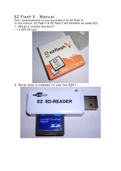
EZ Flash 5 - ManualFirst, congratulations to your purchase of an EZ Flash 5!In this manual, EZ Flash V & EZ Flash 5 will hereafter be called EZ5.1. What's inside the box?• 1 x EZ5 DS card2. What else is needed to use the EZ5?You need a Micro-SD/TransFlash memory card and a computer with a compatible memory card reader (either built-in or external).Please take note that some brands of Micro-SD/TransFlash memory cards have much faster read & write speeds compared to others. The EZ5 can be used even with slow Micro-SD/Transflash cards but in such cases a special tool, the Hybrid tool, may be needed for some games to function properly. Users with faster speed Micro-SD/TransFlash cards will not need to use this tool at all.3. Preparing your Micro-SD/TransFlash memory cardIt is advised that you format your Micro-SD/TransFlash with FAT32 for best performance, although FAT16 will also work.In order for the EZ5 to function properly some files are needed to be placed on your Micro-SD/TransFlash, in a folder called /shell. Download the latest version of these files by going to http://www.plextor.nl. As it can be slow to downloadfiles from Chinese websites, updates can also be found on several US & EU resellers websites, such as http://www.Plextor.NL . Simply extract the archive to your Micro- SD/TransFlash.4. Updating the EZ5 firmware to the latest versionAs the EZ Team continue to improve functions of the EZ5, new updates of the firmware (kernel) will be released. It is advised that you check http://www.plextor.nl periodicallyand download the latest version. Again, updates can also be found on resellers websites, such as http://www.plextor.nl . Once downloaded, extract the file inside the .zip to theroot of your Micro-SD/TransFlash card.You should now have a folder on your Micro-SD/TransFlash called /shell and a file in the root called ez5upldr.binRemove the Micro-SD/TransFlash card from your memory card reader and insert it into your EZ5 card. Next, insert the EZ5 card into your Nintendo DS console and power it up. If your DS is set to autoboot to DS game, press the R button right away. If your DS is set to start with the DS Menu, simply choose to start the "EZ-Flash V" and then press and hold the R button.If done correctly you will be taken to the firmware upgrade area. You can now release the R button. Instructions will be shown on screen. To upgrade the software press the R button again. The update will take about 15 seconds and once done you can press the A button tocontinue to the main EZ5 menu. It is no longer necessary to keep the ez5upldr.bin file on your Micro-SD/TransFlash so feel free to delete it next time you have it connected to your computer.Also found in the firmware upgrade area is an option to make your EZ5 act like a PassMe device. Pressing the L button will enable you to boot SLOT-2 devices (GBA gamepak sized flash cartridges) in DS mode.5. Settings in the EZ5 menuWhen in the EZ5 menu, press L (and hold) and then press R. If done correctly, a Settings screen will appear.The default language is Chinese. If you feel more comfortable with English, press right on the D-pad to set it to English instead.You will also notice a "MicroSD" speed setting. By default it is set to 'Auto Detect' the speed of your Micro-SD/TransFlash. If you later experience problems running games or applications, remember to go to this screen and set the speed manually instead.If possible, you should try to use the EZ5 with a faster Micro-SD/TransFlash card such as PNY, Kingston or Kingmax. EZ Team currently recommend the following manual speed settings:Brand Speed (lower number is faster/better)PNY 3-4Kingston 5-7Kingmax 6-8Sandisk 10-12If you experience problems with white screens when starting games or applications, try to set a higher speed setting. If the problem doesn’t go away, it's possible that you have a slow Micro-SD/TransFlash card and may need to use the Hybrid tool mentioned earlier. You can read about the Hybrid tool in the next paragraph.6. The Hybrid toolThe Hybrid tool was created to allow users with slow Micro-SD/TransFlash cards to still be able to play troublesome games with their EZ5. A handful of known games and applications may have some irregularities with video or music when playing them with a slow Micro-SD/TransFlash card. Running them in through Hybrid tool will help to fix such pproblems.Simply ‘Open’ the game or application you are experiencing problems with. Press ‘Send’ to save the patched game on your hard drive or directly to your Micro-SD/TransFlash card. This process only takes a second or two.A bonus feature of this tool is that it can remove empty space at the end of files so they take up less space on your Micro-SD/TransFlash card. This feature is called ‘Trim’.7. Saves & SavingA dedicated save-chip on your EZ5 card will automatically handle saving for you. When playing games, just save as you would normally do. Save files for all games & applications are stored in a folder called /SAVE. The EZ5 will create a save file for each game & application that you run and place them in this folder. Save files have the same filename as the game or application you ran, but will end with .sav instead of .nds.Different games use different types or saving. There are 5 types of saves: 4K EEPROM, 64K EEPROM, 512K EEPROM, 2M FLASH and 4M FLASH. Some games & applications do not make use of saving at all.The EZ5 knows what type of saving a particular game uses by checking a file called ezsave.lst inside the /shell folder. EZ Team regularly put updated versions of this file on their website so it is advised that you check http://www.plextor.nl from time to time to makesure you are using the latest version. Again, updates can also be found on resellers websites, such as http://www.Plextor.nl . Extract the file to the /shell folder on yourMicro-SD/TransFlash card and overwrite the previous one.It’s also possible for you to change the save type of a game or application manually. This could be needed if the game or application you want to run is not yet included in the ezsave.lst file. If you notice that saving in a game or application does not work, go to the EZ5 menu and move the marker to your game or application. The bottom screen of your DS will show the name of the game or application, a small logo and what type of saving is currently used. To change this preset value, press (and hold) the L button and browse through the different save types with the X and Y buttons. L+Y goes forward in the list, and L+X goes back again.We hope that you will enjoy your EZ Flash 5 for years to come. Always feel free to contact us with suggestions on how we can improve your user experience with the EZ5 and we will do our best to get it done. Thanks!EZ Team & Plextor Teamhttp://www.plextor.nlManual was last updated: January 2nd, 2007.。
Z550中文资料(Intel)中文数据手册「EasyDatasheet - 矽搜」

UNLESS O THERW ISE AGREED IN W RITING BY INTEL, THE INTEL PRO DUCTS ARE NO T DESIGNED NO R INTENDED FO R ANY APPLICATIO N IN W HICH THE FAILURE O F THE INTEL PRO DUCT CO ULD CREATE A SITUATIO N W HERE PERSO NAL INJURY O R DEATH MAY O CCUR.
Contact your local Inte l sale s office or your distributor to obtain the late st spe cifications and be fore placing your product orde r. Copie s of docum ents which have an orde r num be r and are re fere nce d in this docum en
阀门中英文对照

阀门英文对照Handle Nut 手柄螺母Handle Sleeve 手轮套管Hard Seal Butterfly Valves 金属密封碟阀High Temperature Pressure Power Station Gate Valves 高温高压电站闸阀High Temperature Pressure Power Station Globe Valves 高温高压电站截止阀Hoop 卡箍Hayne's alloy 钴铬钨合金High tem perature steel 高温钢Hand-operated valves 手动阀Hard Seal Butterfly Valves 金属密封碟阀Hydraulic relay valves 液压继动阀Hex Hut 手轮螺帽Hydraulic Hand Gun 手动液压加注枪Identification Plate 铭牌Integral Seat 整体阀座Indicator 指示环Indicator Plug 指示塞ISO flange dimensions ISO 法兰尺寸ISO bolt circle ISO 螺栓外径Inside theread 内螺纹Inspection And Test 检验和试验Lifting Eye Bolt 吊眼螺栓Lower Stem 下部阀杆Lower Bearing 下部轴承Lower Bushing 下部衬套Liner 衬垫lug style 吊耳式(蝶阀)Locking Device 锁定装置Lift Check Valves 升降式止回阀Lining Ball Valves 衬里球阀Lining Butterfly Valves 衬里碟阀Lining Check Valves 衬里止回阀Lining Cock 衬里二通Lining Globe Valves 衬里截止阀Lining T-Cock Valves 衬里三通旋塞阀Liquid Indicator 液位计LPG Pipe Fitting 液化气管件Low tem perature steel 低温钢Limit valves 限位阀Lining Ball Valves 衬里球阀Lining Butterfly Valves 衬里碟阀Lining Check Valves 衬里止回阀Lining Cock 衬里二通Lining Globe Valves 衬里截止阀Lining T-Cock Valves 衬里三通旋塞阀Liquid Indicator 液位计LPG Pipe Fitting 液化气管件Line Shaft 中轴metric bolt hole threads 公制螺栓孔螺纹Magnetic Co-operate Globe Valves 磁耦合截止阀Magnetism Forle Pumps 磁力泵Mut 螺母Material chemical analysis and mechanical capacity 材料化学成份和机械性能Materials for main parts 主要零件材料Mechanical capacity 机械性能Max. Discharging Capacity 最大排水量Max. Operating Temperature 最高工作温度Max. Allowable Temperature 最高允许温度Max. Allowable Pressure 最高允许压力Model 型号Magnetic Co-operate Globe Valves 磁耦合截止阀Magnetism Forle Pumps 磁力泵Manual Oil Pumps Valves 手摇油泵(阀)Meter Needle Type Globe Valves 仪表针形截止阀Muffle check valve 消声止回阀Non-Rising Stem 暗杆N.P.T.=美国标准锥管螺纹Name Plate 铭牌Name of parts 零件名称Nominal Pressure 公称压力Nylon 尼龙塑料Nominal Pressure 公称压力NPT and Screwed bonnet 内螺纹和带螺纹阀盖Non Rising Stem Single 暗杆楔式单闸板闸阀Outside Screw and Yoke 外螺纹及支架O-Ring O 型环(密封圈)Outside theread 外螺纹Oxidant 氧化性介质Oblique Stop Valves 直流式截止阀Packing Gland 填料盖Packing 填料Plug Seat Ring 插销阀座垫圈Plug Disc 插销阀瓣Piston Rod Plug 活塞杆塞Piston Rod Plug Pin 活塞杆塞销钉Piston-Disc 活塞瓣Piston Ring 活塞垫圈Piston Ring Collar 活塞垫圈轴套pump discharge or elbows 泵的排泄口或弯头处Plug 插销PACKING SET 填料组合Polytetrafluoroethylene 聚四氟乙烯Pure aluminum 纯铝Pure cupper 纯铜Parallel Slide Valves 浆液阀Pintle valve 针形阀Piping Centrifugal Pumps 管道离心泵Plunger valves 柱塞阀Pressure valve 压力(増压)阀Piping Pumps 管道泵Piping Safety Valves 管道安全阀Plunger Globe Valves 柱塞截止阀Restrictor Valves 过流阀(或节流阀)Pressure-Temperature Benchmark 压力-温度基准PHYSICAL SIZE 尺寸大小Quick Draining Valves 快速排污阀Renewable Seat and Disc 可更换阀座和阀瓣Rubber flange 橡胶法兰Reductant 还原性介质Rising stem 明杆Rubbeer graphite board 橡胶石墨板Reducing valve 减压阀Relief valve 安全泄压阀Rapid closing stop valve 紧急关闭阀Retainer 压环Rocker 摇臂Swing Nut 转轮螺母Spring Shim 弹簧片Split Yoke Bolt Nut 开口支架螺栓螺母Stuffing Box Nut 填料箱螺母Swing Bolt 转轮螺栓Split Yoke Bolt 开口支架螺栓Stuffing Box Bolt 填料箱螺栓Seat Ring 阀座垫圈Stuffing Box Gasket 填料箱垫圈Stem 阀杆Stem Collar 阀杆轴套Set Bushing 固定螺丝Stuffing Box 填料箱Solid Wedge 实心楔板Stem Collar 阀杆轴套Seat Disc Nut 阀座阀瓣螺母Swivel Nut 旋转螺母Screw-in Bonnet 外螺纹阀盖235 solder 235 焊接Seat Disc 阀座阀瓣Semi-Plug Disc 半插销阀瓣Semi-Plug Seat Ring 半插销座垫圈Spring Actuated 弹簧传动Set Bushing 固定螺丝Side Plug 侧面塞子Stop Pin Retainer 止推销定位器steam valves 蒸汽阀门Safety Nut 安全螺母Stem Seal 阀杆密封Switch Box 转换开关盒Stem Kit 阀杆组件Seat 阀座Stem Nut 阀杆螺母Stem 阀杆Stem Washer 阀杆垫圈Stem Packing 阀杆填料Swing Check Valves 旋启式止回阀Screw 螺栓Sealing 密封件Stem 阀杆Stem Mut 阀杆螺母Stem seal 填料Seat testing pressure 压力气密封试验压力Socket 卡套Spring steel 弹簧钢Stainless acid-resisting steel 不锈耐酸钢Stainless and Graphite 不锈钢/石墨Stainless steel 不锈钢Steel Casting iron 碳素钢铸件Shell Test Pressure 壳体试验压力。
标准韩国语第一二三册中文译文

第一册第13课问候(自我介绍)一、课文(1)你好,我是。
李世民:你好,我是李世民。
李世民,你是韩国人吗?李世民:是的。
我是韩国人。
,你是中国人吧?是的,我是中国人。
(2)陈文殊:你好啊,徐晶喜。
徐晶喜:你好,陈文殊。
你是学生吗?陈文殊:是的,我是北京大学的学生。
徐晶喜:我是汉城大学的学生。
主修韩国史。
(3)金永浩:你好,我是金永浩。
王龙:你好,我是王龙。
很高兴见到你。
金永浩:很高兴见到你。
王龙:金永浩是学生吗?金永浩:不是。
我在公司上班的。
王龙你是学生吧?王龙:是的,我是大学生。
第14课学校一、课文(1)洪丹:你好,。
你好,洪丹。
去哪里啊?洪丹:去学校。
这样啊,我们一起去吧。
(2)金永浩:陈文殊,最近忙什么呢?陈文殊:在学韩国语呢。
金永浩:在哪里学习韩国语啊?陈文殊:在汉城大学语言研究所学习韩国语呢。
(3)请朗读。
请写。
认真听。
请跟着做。
请提问。
请回答。
请看黑板。
有问题吗?第15课叙述过去一.课文(1)李世民:王龙,昨天忙什么呐?王龙:在家里看书。
李世民,你(昨天)忙什么?李世民:我(昨天)见朋友去了。
王龙:见谁?李世民:见朴民秀。
王龙:和朴民秀一起都忙些什么?李世民:看电影,还有聊天。
(2)金志永:洪丹,昨天去景福宫和博物馆了吗?洪丹:去景福宫了,但没去博物馆。
金志永:为什么没去博物馆?洪丹:没时间。
金志永,你都忙什么了?金志永:我在家里打扫卫生,还有,稍微休息了下。
第16课买东西一.课文(1)店主:欢迎光临。
顾客:(给我)面包和牛奶。
店主:好的。
顾客:2个面包,1瓶牛奶。
店主:给你(拿好)。
顾客:多少(钱)?店主:950元。
(2)顾客:大叔,这种苹果多少(钱)?店主:500元。
顾客:那种苹果多少(钱)?店主:那种800元。
顾客:那种苹果我买5个。
店主:共4000元。
顾客:给你钱。
店主:再见(请慢走)。
欢迎再惠。
顾客:再见(请留步)。
第17课一天的生活(1)早上6点起床。
先做晨练。
之后,洗漱。
三智眼光 RZSP-4K 4KCH 使用说明书

深圳市三智眼光学仪器有限公司HD200RZ-4K系列产品HD200RZ4KC/4KCH使用说明书目录第一章引言 (4)1.1概述 (4)1.2产品参数 (4)1.3接口介绍 (4)1.4本书读者 (5)第二章相机功能介绍 (5)2.1开机界面 (5)2.2视频界面 (5)2.3视频控制区 (6)2.3.1预览开关 (6)2.3.2拍照 (6)2.3.3录像 (6)2.3.4白平衡 (7)2.3.5自动曝光 (7)2.3.6视频界面模式 (8)2.3.7文件管理 (8)2.3.8图像比例调节 (10)2.3.9截屏 (11)2.4测量工具 (11)2.4.1测量操作说明 (11)2.4.2铅笔 (12)2.4.3注释 (12)2.4.4保存图元 (12)2.5测量设置 (13)2.5.1定标创建与删除 (13)2.5.2比例尺 (14)2.5.3刻度线 (14)2.5.4其他 (14)2.6测量数据 (15)2.7视频设置 (15)2.8系统设置 (15)2.8.1保存参数模板 (16)2.8.2风扇控制 (16)2.8.3系统更新 (16)2.8.4恢复出厂 (17)2.8.5版本号 (17)2.9动态功能区 (17)2.9.1动态信息 (17)2.9.2功能开关 (17)2.9.3休眠及定时休眠 (18)第一章引言1.1概述RZSP-4K相机产品采用SONY高端CMOS感光芯片,双CPU处理器,色彩清晰自然,响应迅速,细节丰富细腻,内置8G存储空间,智能风扇散热技术,保证相机更加稳定。
1.2产品参数1.3接口介绍1.4本书读者本操作手册主要面向使用该系列相机的用户。
第二章相机功能介绍2.1开机界面相机通电后显示开机界面(如图2.1-1),进度条过后进入视频界面(如图2.2-1)。
图2.1-12.2视频界面图2.2-12.3视频控制区2.3.1预览开关开始预览暂停预览2.3.2拍照在视频模式下,点击,视频图像将以jpg格式保存到相机内部SD卡或外存储设备。
Rocker 35 EZ用户手册说明书

Rocker 35 EZUser ManualS2035-ES2035-E-230VS2035-DES2035-DE-230VTABLE OF CONTENTS Page 1.0. GENERAL DESCRIPTION (3)1.1. DEFINITION (3)1.2. PRINCIPLE OF OPERATION (3)2.0. TECHNICAL FEATURES (3)2.1. CONSTRUCTION (3)2.2. GENERAL FEATURES (3)3.0. INSTALLATION (4)3.1. UNPACKING (4)3.2. SELECTING THE RIGHT PLACE (4)3.3. ATTACHING THE POWER CORD (4)3.4. ENVIRONMENT CONDITIONS (5)4.0. INSTRUCTIONS FOR USE (5)4.1. INTRODUCTION (5)4.2. OPERATION (5)4.3. ADJUSTING TILT ANGLE (6)5.0. SAFETY (7)6.0. TROUBLESHOOTING GUIDE (7)7.0. REGULAR MAINTENANCE (8)7.1. CLEANING (8)8.0. INSTALLATION OF DOUBLE PLATFORM (9)1.0. GENERAL DESCRIPTION1.1. DESCRIPTIONRocker 35 EZ is a general purpose adjustable tilt rocker with digital time and speed controls. The tilt angle is easily adjustable without tools using the knob on right side of unit. This reliable rugged unit is designed for extended use and comes with a 5 year warranty.1.2. PRINCIPLE OF OPERATIONThe motor is designed to generate a rocking effect while the electronic interface controls the RPM and Time features.2.0. TECHNICAL FEATURES2.1. CONSTRUCTIONThe housing of the rocker is made of plastic and steel plate varnished with high resistant polyurethane lacquer.2.2. GENERAL FEATURESELECTRIC POWER SUPPLY 230V ± 10%, 50/60Hz or 115V ± 10%, 50/60Hz MOTOR POWER 6 WFUSES 2 x 1AT (for 230V and 115V power supply)RPM REGULATION Microcontroller, load independent, from 10 to 120RPMTILT ANGLE 0 - 20° from horizontalTIMER 10 - 120 min, HOLD functionkgLOAD Max.5 DIMENSIONS W x D x H 360 x 360 x 170 mm (single platform)360 x 360 x 260 mm (double platform)PLATFORM DIMENSIONS W X D 360 x 280 mmWEIGHT 6.5 kg (single platform), 7.8 kg (double platform) AMBIENT CONDITIONS -10°C to 70°C, up to 85% RH, non-condensing3.0. INSTALLATION3.1. UNPACKINGBefore starting the installation, carefully examine the delivery for possible damage or missing parts.- Open the box and lift the device together with shock absorbers out of the box.- Remove the shock absorbers and check that the rocker has not been visibly damaged during the transportation. Keep the packing material until you are sure that the rocker works properly.- Check information on rocker name plate:- Type- Serial Number- Product number- Check that the mains cord has a pin configuration that will fit into a wall socket according to the local standard.Should any kind of damage have occurred during transportation, immediately make a complaint to the carrier. Any incorrect delivery or missing parts should be reported to the distributor.3.2. SELECTING THE RIGHT PLACEWhen selecting the right place for device, please consider following:- Put the device on smooth, horizontal and stable place.- Leave enough space beyond the device for normal air circulation, min. 10 cm.- Leave enough space around the device, that you will easy control and maintain it.- Don't use the device in surroundings, where there are fast temperature and humidity changes. Please avoid also such places, which are under direct access of sun light or places nearby devices which producing heat.- Avoid such places, where possibility of shocks and vibrations exists.NOTE: The equipment shall not be placed so, that it is difficult to pull out a mains cord plug from wall socket.3.3. ATTACHING THE POWER CORDFit the mains cord, which is included in the delivery, into the mains receptacle on the back side of rocker. Connect the other end of the cord to a grounded wall socket. To avoid interference from noise, surges and spikes, a special line is preferred. If no such line is available, avoid lines to which powerful electric motors, refrigerators and similar devices are connected.The power can be turned on and off by main switch located on the front panel of the device. Light, mounted in the switch indicates that power is on.Take care when you plug mains cord to a grounded wall socket. Do nottouch the plug with wet hands, because it can be very dangerous. Plugmains cord to a grounded wall socket only with dry hands.3.4. ENVIRONMENT CONDITIONSThe rocker has been built for operating in laboratory environment. Therefore the environmental reference parameters are the following:∙Temperature between -10°C to +70°C∙Humidity up to 85% RH, non-condensing4.0. INSTRUCTIONS FOR USE4.1. INTRODUCTION2. SPEED knob - to set the rocker speed.3. TIME knob - to set the time of operation.4. HOLD yellow signal light - illuminates when the rocker is set to HOLD (continuousoperation).5. START/STOP key - to START or STOP the rocking operation.6. RUN green signal light - illuminates when the rocker is running.4.2. OPERATION1. Turn POWER switch ON (it should illuminate).2. Set SPEED knob to desired value.3. Set TIME knob to desired value or to HOLD - continuous operation (yellow signallight HOLD must illuminate).4. Press START/STOP key to start the rocking operation.5. Device automatically stops after the set time passes.6. If you want to stop the rocking operation before the set time passes, or when TIMEknob is set to HOLD, press START/STOP key.NOTE: Pressing START/STOP key during operation will reset the timer.It's possible to change speed during operation, but you cannot change time. If you want to change time, stop the rocker, set desired time and start it again.Do not put your hands between platform and housing during operation,because your fingers can get pinched.1 2 364.3. ADJUSTING TILT ANGLENOTE: Before you adjust the tilt angle, rocker must be STOPPED. Stop the rocker ina position, where marking on the knob, located on the right side of the housing, is aligned with arrow on the label (see picture below). Do this by operating the rocker at low speed (20 - 30 RPM). Only when marking and arrow are aligned, then it's easy to adjust tilt angle of rocker platform.How to adjust tilt angle:1. Stop the rocker in a position described above and unload the platform.2. Loosen the knob on the right side of the rocker housing, by rotating it counter-clockwise.3. Adjust the platform to desired tilt angle by moving it up or down and looking on the degree scale (see above) on the platform drive shaft (front center under platform).4. Tighten the knob on the right side by turning it clockwise. Test the unit without load to ensure platform is tight.Now rocker is ready for operation with new desired tilt angle.5.0. SAFETY- Do not use the device nearby water sources. Take care, that water will not drop in the device, especially by cleaning procedures.- Do not use the device in aggressive atmosphere.- To avoid shock hazards or destroying the device, do not put any electrical conducting objects into the device. It could happen that you would touch dangerous voltage points.In case of malfunction, unplug the device from mains power supply and call authorized service. You have to call the service in the following cases also: - Mains cord or mains receptacle are harmed or destroyed. - Liquid was dropped into the device.NOTE: In case that device is not functioning properly, even if you have exactlyfollowed instructions described in User's Manual, you are allowed to use only those commands and procedures, which are described by User's Manual. Use of any other commands, procedures and adjustments could result in device destruction or longer service repair time.If the equipment is used in a manner not specified by the manufacturer, the protection provided by the equipment may be impaired.Do not shake inflammable or explosive samples!6.0. TROUBLESHOOTING GUIDEReview the information in the table below to troubleshoot operating problems. In case of malfunction, unplug the device from main power supply and contact Labnet International, Inc. Service Department at (732) 417-0700 Monday through Friday 8:30am – 5pm EST.Problem Explanation / SolutionPOWER switch doesn't illuminate when turned ON. Check the connection to main power supply. Check fuses.Call authorized service.Rocker doesn't start when you press START/STOP key. Check the connection to main power supply. Check fuses.Call authorized service.HOLD yellow signal light and RUN green signal light are blinking. Motor overload - reduce the load on the platform. Call authorized service.7.0. REGULAR MAINTENANCE∙No routine maintenance or lubrication is required.∙It is recommended that the rocker is kept clean to ensure long trouble-free operation. 7.1. CLEANINGThe housing of the rocker can be cleaned with a soft, damp cloth or special cleaners for plastic surfaces (e.g. for car interior - armature). Do not immerse the device or spill liquids on the device.NOTE: Do not use any aggressive or abrasive cleaners (acetone, nitro, polish etc.) because the surface can get permanently damaged.Prior to any cleaning or maintenance of the device, unplug the powercord from the wall socket.8.0. INSTALLATION OF DOUBLE PLATFORMBefore the installation of double platform, turn off the POWER switch.For installation of double platform, prepare upper platform with rubber pad and posts kit, which includes four posts, four washers, four screws and four nuts.1. Set four posts (A) above four holes at the corners of the bottom platform.2. Put the washer (B) on each screw (C) and then screw it into each post from the bottom side of the platform.3. Fit upper platform (D) on the top of four posts, so that the threads of the posts are protruding through four corner holes.4. Screw four nuts (E) on the threads of four posts, to fix the upper platform.AB CDEA B CE Posts kitThis equipment is marked with the crossed outwheeled bin symbol to indicate that this equipment mustnot be disposed of with unsorted waste.Instead it’s your responsibility to correctly dispose ofyour equipment at lifecycle-end by handing it over to anauthorized facility for separate collection and recycling.It’s also you responsibility to decontaminate theequipment in case of biological, chemical and/orradiological contamination, so as to protect from healthhazards the persons involved in the disposal andrecycling of the equipment.For more information about where you can drop off your waste equipment,please contact your local dealer from whom you originally purchased thisequipment.By doing so, you will help to conserve natural and environmental resources and you will ensure that your equipment is recycled in a manner that protects human health.Thank youVersion 1.0 March 2016LIMITED WARRANTYLabnet International, Inc. warrants that this product will be free from defects in material and workmanship for a period of one (1) year from date of purchase. This warranty is valid only if the product is used for its intended purpose and within the guidelines specified in the supplied instruction manual.Should this product require service, contact Labnet International, Inc.’s Service department at 732-417-0700 to receive a return authorization number and shipping instructions. Products received without proper authorization will be returned. All items returned for service should be sent postage prepaid in the original packaging or other suitable carton, padded to avoid damage. Labnet International, Inc. will not be responsible for damage incurred by improper packaging. Labnet International, Inc. may elect for onsite service for larger equipment.This warranty does not cover damage caused by accident, neglect, misuse, improper service, natural forces or other causes not arising from defects in original material or workmanship. This warranty does not cover motor brushes, fuses, light bulbs, batteries or damage to paint or finish. Claims for transit damage should be filed with the transportation carrier.ALL WARRANTIES INCLUDING THE IMPLIED WARRANTY OF MERCHANTABILITY AND FITNESS FOR A PARTICULAR PURPOSE ARE LIMITED IN DURATION OF 12 MONTHS FROM THE ORIGINAL DATE OF PURCHASE.LABNET INTERNATIONAL, INC.’S SOLE OBLIGATION UNDER THIS WARRANTY IS LIMITED TO THE REPAIR OR REPLACEMENT, AT LABNET INTERNATIONAL, INC. DISCRETION, OF A DEFECTIVE PRODUCT. LABNET INTERNATIONAL, INC. IS NOT LIABLE FOR INCIDENTAL OR CONSEQUENTIAL DAMAGE, COMMERCIAL LOSS OR ANY OTHER DAMAGES RESULTING FROM THE USE OF THIS PRODUCT.Some states do not allow limitation on the length of implied warranties or the exclusion or limitation of incidental or consequential damages. This warranty gives you specific legal rights. You may have other rights which vary from state to state.No individual may accept for, or on behalf of Labnet International, Inc., any other obligation of liability, or extend the period of this warranty.✂ cut along the dotted lineTo validate the warranty, complete and return this card within 10 days.Mail Warranty Registration to : or Register online atLabnet International, Inc. 31 Mayfield Ave.Edison, NJ 08837。
Z3计算机

1936年,图灵发表的研究报告对计算机和计算机科学领域造成巨大冲击,这篇报告主要是为了证明循环处理 程式的死角,亦即停机问题的存在。图灵也以算法概念为通用计算机(纯理论器件)作出定义,后来称为图灵机, 取代哥德尔渐趋累赘的通用语言。除了内存限制,现代电脑已经具备图灵完全的条件,也就是说,现代电脑的算 法执行力已与通用图灵机相当。内存限制有时也被视为一般用途电脑与特殊用途电脑的差别。
明年是楚泽诞辰100周年,为纪念这位杰出的发明家,许恩费尔德市宣布将由楚泽之子霍斯特·楚泽 (Horst Zuse)完全按照楚泽当年的设计方案重新制造一台Z3电脑。制成后将首先在许恩费尔德,然后在柏林等 地作现场表演,向公众展示最早的计算机是如何工作的。最后Z3将正式落户于许恩费尔德市的康拉德·楚泽博物 馆。Z3
Z3计算机
第一台可编程的电磁式计算机
01 产品介绍
03 主要参数
目录
02 简介 04 早期的数位电脑
目录
05 楚泽Z系列
07 Z3将复制展出
06 克兰德·楚泽
基本信息
楚泽完成了Z3计算机的研制工作,这是第一台可编程的电磁式计算机。可处理7位指数、14位小数。使用了 大量的真空管。每秒种能作3到4次加法运算,一次乘法需要3到5秒。
克兰德·楚泽1910年6月22日生于德国维尔梅斯多夫,在东普鲁士接受的早期教育。东普鲁士的文化传统相 当保守,为了获得更好的发展,他进入一所比较开放的学校,直到高中毕业。1927年,楚泽考进柏林工业大学, 学的是土木工程建筑专业。他从小爱好绘画,具有非常好的美术功底,因此很快就学会了如何设计房屋结构和外 观。多才多艺的楚泽兴趣广泛,修理机器的活也很拿手,时常动手制作出一些稀奇古怪的玩艺,让班上的同学大 吃一惊。
5z3整流电压

5z3整流电压
5Z3整流电压是指使用5Z3管进行整流时输出的电压。
5Z3是一种直线型全波整流管,常用于电源和音响放大器等应用中。
特点:
1. 高压输出:5Z3整流管可以输出较高的直流电压,通常在350V至450V之间。
2. 大电流容量:5Z3整流管具有较高的电流容量,可以承受较大的负载电流。
3. 稳定性好:5Z3整流管的输出电压相对稳定,能够提供较为可靠的直流电源。
4. 耐久性强:5Z3整流管的寿命较长,能够经受较长时间的工作。
作用:
1. 整流:5Z3整流管将交流电转换为直流电,使交流电的正半周和负半周都能被利用起来,提供稳定的直流电源。
2. 滤波:5Z3整流电压经过滤波电路进行滤波,去除输出中的纹波信号,使输出电压更加稳定。
3. 电源:5Z3整流电压作为电源供给其他电子设备,如音响放大器、无线电接收机等,提供所需的直流电能。
总之,5Z3整流电压具有高压输出、大电流容量、稳定性好和耐久性强的特点,主要用于将交流电转换为稳定的直流电源,供给其他电子设备使用。
需要根据企业自身的特点和目标受众来
确定具体的宣传策略,并结合抖音平台的特点和用户行为习惯来制定执行计划。
同时,也要密切关注数据分析和用户反馈,及时调整和优化宣传策略,以达到最佳的宣传效果。
美国赛智剃须刀五刀头中文说明书
美国赛智剃须刀五刀头中文说明书
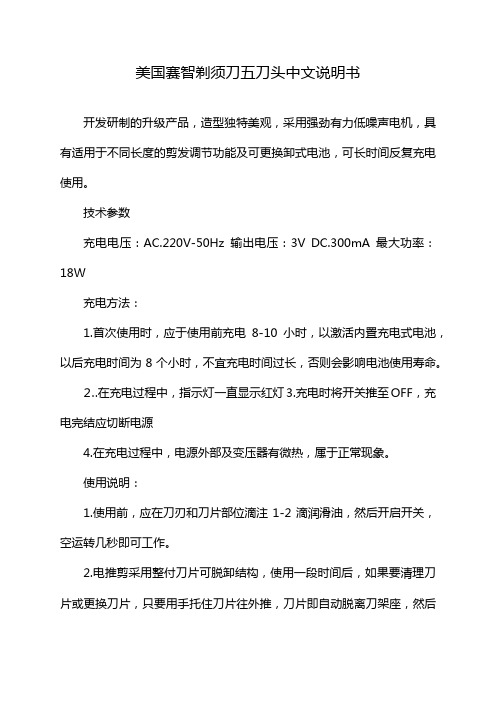
开发研制的升级产品,造型独特美观,采用强劲有力低噪声电机,具有适用于不同长度的剪发调节功能及可更换卸式电池,可长时间反复充电使用。
技术参数
充电电压:AC.220V-50Hz输出电压:3V DC.300mA最大功率:18W
充电方法:
1.首次使用时,应于使用前充电8-10小时,以激活内置充电式电池,以后充电时间为8个小时,不宜充电时间过长,否则会影响电池使用寿命。
⒉.在充电过程中,指示灯一直显示红灯3.充电时将开关推至OFF,充电完结应切断电源
4.在充电过程中,电源外部及变压器有微热,属于正常现象。
使用说明:
1.使用前,应在刀刃和刀片部位滴注1-2滴润滑油,然后开启开关,空运转几秒即可工作。
2.电推剪采用整付刀片可脱卸结构,使用一段时间后,如果要清理刀片或更换刀片,只要用手托住刀片往外推,刀片即自动脱离刀架座,然后
可以清理,安装时用手抓紧刀片,调节圈调至2.0mm位置,对准刀座内缺口向内用力推,直至咔嚓一声后即可。
3.本电推剪设计为交直两用,如果充电电池内的点用完,可将充电器插上220V~50Hz电源,带线使用效果不变。
4.该电推剪配有2组电池,轮换使用,均可脱机充电或待机充电。
1、机身时尚高雅,符合人体工程学设计
2、强劲马达、低振动,超静音设计
3、特殊合金钢、陶瓷刀片,锋利、耐磨,能剪切大量头发
4、高容量镍氢充电池,充满电后可连续使用一个小时左右
5、五档尺寸可调节刀片,剪发长度可从0.8-2.0毫米。
z3m可控硅参数

z3m可控硅参数【原创实用版】目录1.引言2.z3m 可控硅的基本参数3.z3m 可控硅的工作原理4.z3m 可控硅的应用领域5.结论正文1.引言z3m 可控硅,全称为 Zener 三极管可控硅,是一种半导体器件,具有电压控制的开关特性。
它广泛应用于交直流转换、逆变器、斩波器、调压器等电子设备中。
本文将对 z3m 可控硅的参数、工作原理以及应用领域进行详细介绍。
2.z3m 可控硅的基本参数z3m 可控硅的主要参数有:额定电压、额定电流、控制电压、关断电压、开通电压等。
- 额定电压:z3m 可控硅的额定电压是指其可以正常工作的最大电压。
通常情况下,z3m 可控硅的额定电压在几十到几百伏之间。
- 额定电流:z3m 可控硅的额定电流是指其可以正常通过的最大电流。
通常情况下,z3m 可控硅的额定电流在几安到几十安之间。
- 控制电压:z3m 可控硅的控制电压是指通过控制该电压,可以使可控硅导通或截止。
通常情况下,z3m 可控硅的控制电压在几伏到几十伏之间。
- 关断电压:z3m 可控硅的关断电压是指当电压降至一定程度时,可控硅会自动截止。
通常情况下,z3m 可控硅的关断电压在其额定电压的60%~80% 之间。
- 开通电压:z3m 可控硅的开通电压是指当电压升至一定程度时,可控硅会自动导通。
通常情况下,z3m 可控硅的开通电压在其额定电压的80%~100% 之间。
3.z3m 可控硅的工作原理z3m 可控硅的工作原理主要基于 PN 结的导通和截止。
在可控硅的结构中,有一个 N 型区、一个 P 型区和一个 N 型区。
当控制电压加在可控硅的控制极上时,如果控制电压大于关断电压,那么可控硅就会导通。
反之,如果控制电压小于开通电压,那么可控硅就会截止。
4.z3m 可控硅的应用领域z3m 可控硅广泛应用于交直流转换、逆变器、斩波器、调压器等电子设备中。
例如,在家用电器中,可控硅可以用于调节电压、电流,实现节能降耗。
在工业领域,可控硅可以用于实现对电机、电源等设备的精确控制。
- 1、下载文档前请自行甄别文档内容的完整性,平台不提供额外的编辑、内容补充、找答案等附加服务。
- 2、"仅部分预览"的文档,不可在线预览部分如存在完整性等问题,可反馈申请退款(可完整预览的文档不适用该条件!)。
- 3、如文档侵犯您的权益,请联系客服反馈,我们会尽快为您处理(人工客服工作时间:9:00-18:30)。
ã 2001 Semtech Corp.
4
元器件交易网
EZ5Z3
POWER MANAGEMENT Outline Drawing - TO-220
Contact Information
Semtech Corporation Power Management Products Division 652 Mitchell Rd., Newbury Park, CA 91320 Phone: (805)498-2111 FAX (805)498-3804
1
元器件交易网
EZ5Z3
POWER MANAGEMENT Absolute Maximum Ratings
Parameter Power D i ssi pati on C onti nuous C urrent Thermal Resi stance Juncti on to Ambi ent SOT-223 TO-220 Thermal Resi stance Juncti on to C ase SOT-223 TO-220 Operati ng Ambi ent Temperature Range Operati ng Juncti on Temperature Range Storage Temperature Range Lead Temperature (Solderi ng) 10 Sec. ESD Rati ng (Human Body Model) Sy mbol PD IC q JA Maximum 2 1 62 50 4 4 -40 to 125 -40 to 150 -65 to 150 300 2 U nits W A °C /W ° 0.01
%VOUT %VOUT/°C
ã 2001 Semtech Corp.
2
元器件交易网
EZ5Z3
Ordering Information
D ev ice EZ5Z3-S3.3.TR EZ5Z3-SAD J.TR EZ5Z3-T3.3 EZ5Z3-TAD J VIN 5 5 P ackag e SOT-223(1) TO-220(2) VOUT Volts 3.3 AD J 3.3 AD J
POWER MANAGEMENT Pin Configurations
SOT-223 TO-220
Pin 1 2 3 Function (-3.3) NC OUT IN TAB i s OUT Function (-AD J) ADJ OUT IN
Notes: (1) Only available in tape and reel packaging. A reel contains 2500 devices. (2) Only available in tube packaging. A tube contains 50 devices.
Parameter EZ5Z3-3.3
Sy mbol VOUT
C onditions VIN = 5V, IOUT = 500mA VIN = 5V, 10mA £ IOUT £ 1A
Min 3.20 3.13 1.21 1.18
Ty p 3.30
Max 3.39 3.46
U nits V
EZ5Z3-AD J
ã 2001 Semtech Corp.
5
q JC TA TJ TSTG TLEAD V ESD
°C °C °C °C kV
Electrical Characteristics
Unless specified: TA = 25°C. Values in bold apply over the full operating ambient temperature range.
元器件交易网
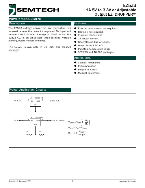
POWER MANAGEMENT Description
The EZ5Z3 voltage converters are innovative two terminal devices that accept a regulated 5V input and reduce it to 3.3V over a range of 10mA to 1A. The EZ5Z3-ADJ is an adjustable three terminal version allowing output voltage trimming. The EZ5Z3 is available in SOT-223 and TO-220 packages.
1A 5V to 3.3V or Adjustable Output EZ DROPPER
Features
u u u u u u u u u u u u
External components not required Heatsink not required 2 simple connections 1A output current Generates no EMI or spikes Drops 5V to 3.3V, ADJ Industrial temperature range SOT-223 and TO-220 packages
1
U1 5V IN 3 IN
EZ5Z3-ADJ 2 OUT ADJ 1
0.1V to 3.7V OUT
R1
R2
R1 VDROP = VREF 1+ R 2 VOUT = VIN − VDROP V R1 + R2 ≤ DROP 300 µA
Revision 1, January 2001
EZ5Z3
Applications
Cellular Telephones Instrumentation Peripheral Cards Medical Equipment
Typical Application Circuits
U1 5V IN 3 IN EZ5Z3-3.3 2 OUT NC
3.3V OUT
Symbol
EZ5Z3-3.3
EZ5Z3-ADJ
ã 2001 Semtech Corp.
3
元器件交易网
EZ5Z3
POWER MANAGEMENT Outline Drawing - SOT-223
Land Pattern - SOT-223
VREF
VIN = 5V, IOUT = 500mA VIN = 5V, 10mA £ IOUT £ 1A
1.25
1.28 1.31
V
Load Regulati on Temperature C oeffi ci ent
REG(LOAD) TC
VIN = 5V, IOUT = 10mA to 1A VIN = 5V, IOUT = 500mA