APC3216MGC-F01中文资料
全自动钢坯喷码机PLC控制系统设计
全自动钢坯喷码机PLC控制系统设计目录摘要------------------------------------------------------------------------1 英文摘要-----------------------------------------------------------------------1 1 绪论-------------------------------------------------------------------------2 1.1 项目研究的背景-------------------------------------------------------------21.1.1国外打标机的发展-----------------------------------------------------21.1.2我国打号机的发展现状------------------------------------------------4 1.2钢坯打标机在炼钢生产中的作用----------------------------------------------51.3课题的提出及意义-----------------------------------------------------------52 气动回路设计-------------------------------------------------------6 2.1气动回路设计-----------------------------------------------------------------62.1.1气动回路的设计思路--------------------------------------------------62.1.2气动回路图的设计----------------------------------------------------62.2气动回路图各元件型号选择及其性能分析----------------------------------------73 硬件系统设计--------------------------------------------------------13 3.1 PLC型号选择及其性能分析--------------------------------------------------133.1.1可编程控制器的应用和发展-----------------------------------------------133.1.2 PLC的工作原理及其性能分析--------------------------------------------- 17 3.2 PLC中CPU的选择----------------------------------------------------------- 18 3.3电机的选择及其分析-----------------------------------------------------193.3.1步进电机的选用及分析-------------------------------------------------193.3.2三相异步电动机的选用及分析---------------------------------------------- 20 3.4传感器型号选择及其性能分析-------------------------------------------------- 223.4.1激光测距传感器------------------------------------------------------ 223.4.2 透射式电涡流测厚传感器---------------------------------------------- 224 软件设计部分-----------------------------------------------------25 4.1各运行部分之间距离与延时时间的设定--------------------------------------254.1.1各零件距离设定----------------------------------------------------254.1.2各运行速度设定----------------------------------------------------254.1.3其他值的计算------------------------------------------------------25 4.2 PLC控制系统流程的设计--------------------------------------------------264.2.1系统描述----------------------------------------------------------264.2.2 PLC控制系统------------------------------------------------------274.2.3PLC控制系统的扩展配置-------------------------------------------274.2.4程序主流程-------------------------------------------------------28 4.3 PLC的I/O地址分配-----------------------------------------------------31 4.4设计PLC的外部接线图---------------------------------------------------31 4.5电机控制电路主回路-----------------------------------------------------32 4.6设计梯形图程序------------------------------------------------------------334.6.1编写梯形图的软件介绍------------------------------------------------334.6.2用PLC对步进电机的控制方式描述-------------------------------------344.6.3采用多段管线PTO输出控制步进电机-----------------------------------374.6.4 PLC的抗干扰措施----------------------------------------------------465 研究工作的总结----------------------------------------------------476 致谢--------------------------------------------------------------487 参考文献----------------------------------------------------------498 附录--------------------------------------------------------------50附录一:气动回路设计图附录二:PLC编程程序梯形图全自动钢坯喷码机PLC控制系统设计摘要:工业自动化技术在近年来发展十分迅猛,当前工业自动化三大支柱技术之一的PLC技术以其很高的可靠性和抗干扰能力受到广泛的欢迎,在各行各业的技术改造过程中被大量地应用。
WCM3216F2SF

WCM3216F2SF-SERIESTypical Impedance v.s. Frequency Curve110100100010000FREQUENCY(MHz)0.11101001000I M P E D A N C E (O h m )WCM3216F2SF-900Common ModeNormal Mode110100100010000FREQUENCY(MHz)0.11101001000I M P E D A N C E (O h m )WCM3216F2SF-161Common ModeNormal Mode110100100010000FREQUENCY(MHz)0.11101001000I M P E D A N C E (O h m )WCM3216F2SF-221Common ModeNormal ModeSeriesA(mm)3216F2SF 3.2±0.2A: SeriesB: DimensionC: Material Ferrite D: Number of Lines 2=2 linesE: Type S=One Circuit Type , N=Unshielded F: Lead free typeG: Impedance 900=90ΩH: Packaging T=Taping and Reel, B=Bulk I: Rated Current 04=400mA產品破損寬度7. Soldering and MountingPC board should be designed so that products are not sufficient under mechanicalstress as warping the board.Products shall be positioned in the sideway direction against the mechanical stress toprevent failure.7-2. SolderingMildly activated rosin fluxes are preferred. The minimum amount of solder can lead to damage from the stresses caused by the difference in coefficients of expansion between solder, chip and substrate. TAI-TECH terminations are suitable for all wave and re-flow soldering systems. If hand soldering cannot be avoided, the preferred technique is the utilization of hot air soldering tools.7-2.1 Lead free Solder re-flow:Recommended temperature profiles for re-flow soldering in Figure 1.7-2.2 Solder Wave:Wave soldering is perhaps the most rigorous of surface mount soldering processes due to the steep rise in temperature seen by the circuit when immersed in the molten solder wave. Due to the risk of thermal damage to products, wave soldering of large size products is discouraged. Recommended temperature profile for wave soldering is shown in Figure 2.7-2.3 Soldering Iron(Figure 3):Products attachment with a soldering iron is discouraged due to the inherent process control limitations. In the event thata soldering iron must be employed the following precautions are recommended.Note:‧Preheat circuit and products to 150℃‧Never contact the ceramic with the iron tip ‧Use a 20 watt soldering iron with tip diameter of 1.0mm ‧280℃tip temperature (max) ‧1.0mm tip diameter (max) ‧Limit soldering time to 3 sec.8-4. Tearing Off ForceThe force for tearing off cover tape is 15 to 60 gramsin the arrow direction under the following conditions.。
MLV3216N180中文资料

MLV1005 Series MLV1608 Series MLV2012 Series MLV3216 Series MLV3225 Series Normal Type MultilayerVaristorFeatures• Monolithic Multilayer Construction with 1005, 1608, 2012, 3216 and 3225 Model Sizes• Wide Operating Voltage Range V DC =3.3V to 48V• Excellent Nonlinear Voltage-Current Characteristics with Low Clamping Voltage and Large Surge Current/Energy Handing Capabilities at Small Size•Available in Tape and Reel or Bulk PackMaximum Ratings• Operating Ambient Temperature Range: -55к to +125к•Leakage Current: 1. < 50A at ambient temp.2. <100A for3.3V DC(Test Conditions: The current measured with V DC applied) • Maximum Surge Energy (WS): V 1mA / V 1mA ̰f 10%Test Conditions: On standard circumstance Impulse the10/1000s specified current wave 1 time ,Measure the variation of V 1mA• Maximum Surge Current (I S ): V 1mA / V 1mA ̰f 10%Test Conditions: 1 At room temperature and humidity2. 8/20s waveform3. Impulse of +/- polarity4. Measure the variation of V1mA omp onents 20736 Marilla Street Chatsworth! "# $ % ! "#Micro Commercial ComponentsElectrical CharacteristicsMaximum TransientPart NumberWorking VoltageBreakdown VoltageClamping Voltage1Surge Current Surge Energy TypicalCapacitance Symbol V RMSV DCV B V C I S W S CUnits Volts(max.)Volts(max.)Volts Volts(max.)Amps(max.)Joules(max)PF(typ.)0.5V rms Test Condition1mA DC8/20s (1A)8/20s 10/1000s1KHzMLV1005N030 2.5 3.3 5(4.4-6.0) 10 20 0.05 390 MLV1005N050 4 5.58(6.4-9.6)16 200.05295MLV1005N090 6 9 12(9.6-14.4) 20 200.05190MLV1005N1108 11 15(12.75-17.25) 25 200.05160MLV1005N14011 14 18(16.5-20.3) 30 200.05135MLV1005N16012 16.5 22(19.8-24.2) 36 200.05105MLV1005N18014 18 24(21.6-27) 40 200.0593MLV1005N22017 22 27(24.3-29.8) 45 200.0575MLV1005N26020 26 33(29.7-36.3) 54 200.0554MLV1005N30025 30 39(35.1-42.9) 65 200.0545MLV1005N38030 38 47(42.3-51.7) 77 200.0527MLV1608N030 2.5 3.3 5(4.4-6.0) 10 30 0.1 1250 MLV1608N050 4 5.58(6.4-9.6)16 300.1800MLV1608N090 6 9 12(9.6-14.4) 20 300.1680MLV1608N1108 11 15(12.75-17.25) 25 300.1460MLV1608N14011 14 18(16.5-20.3) 30 300.1350MLV1608N16012 16.5 22(19.8-24.2) 36 300.1300MLV1608N18014 18 24(21.6-27) 39 300.1270MLV1608N22017 22 27(24.3-29.8) 44 300.1235MLV1608N26020 26 33(29.7-36.3) 54 300.1200MLV1608N30025 30 39(35.1-42.9) 65 300.1120MLV1608N38030 38 47(42.3-51.7) 77 300.1100MLV1608N45035 45 56(50.4-61.6)90 30 0.180MLV1005,1608,2012,3216,3225 SERIESTMMicro Commercial Componentswww.mccsemi .comElectrical CharacteristicsMaximum TransientPart NumberWorking VoltageBreakdown VoltageClamping Voltage 1Surge Current Surge Energy TypicalCapacitance Symbol V RMSV DCV B V C I S W S CUnits Volts(max.)Volts(max.)Volts Volts(max.)Amps(max.)Joules(max)PF(typ.)0.5V rms Test Condition1mA DC8/20s (1A)8/20s 10/1000s1KHzMLV2012N030 2.5 3.3 5(4.4-6.0) 10 40 0.1 2450 MLV2012N050 4 5.58(6.4-9.6)16 80 0.11600MLV2012N090 6 9 12(9.6-14.4) 20 80 0.1 1180 MLV2012N1108 11 15(12.75-17.25) 25 100 0.1 1050 MLV2012N14011 14 18(16.5-20.3) 30 100 0.1 750 MLV2012N16012 16.5 22(19.8-24.2) 36 100 0.2 680 MLV2012N18014 18 24(21.6-27) 39 100 0.2 550 MLV2012N22017 22 27(24.3-29.8) 44 100 0.3 400 MLV2012N26020 26 33(29.7-36.3) 54 100 0.3 350 MLV2012N30025 30 39(35.1-42.9) 65 100 0.3 310 MLV2012N38030 38 47(42.3-51.7) 77 100 0.3 280 MLV2012N45035 45 56(50.4-61.6)90 80 0.3195 MLV2012N56040 56 68(61.2-74.8) 110 80 0.3 145 MLV2012N65050 65 82(73.8-90.2) 135 60 0.3 85MLV3216N030 2.5 3.3 5(4.4-6.0) 10 60 0.1 3850 MLV3216N050 4 5.58(6.4-9.6)16 100 0.23200MLV3216N090 6 9 12(9.6-14.4) 20 100 0.2 2200 MLV3216N1108 11 15(12.75-17.25) 25 100 0.2 1300 MLV3216N14011 14 18(16.5-20.3) 30 100 0.3 1150 MLV3216N16012 16.5 22(19.8-24.2) 36 100 0.3 1000 MLV3216N18014 18 24(21.6-27) 38 100 0.3 900 MLV3216N22017 22 27(24.3-29.8) 44 100 0.4 840 MLV3216N26020 26 33(29.7-36.3) 54 100 0.5 490 MLV3216N30025 30 39(35.1-42.9) 65 100 0.6 440 MLV3216N38030 38 47(42.3-51.7) 77 100 0.7 400 MLV3216N45035 45 56(50.4-61.6)90 100 0.8310 MLV3216N56040 56 68(61.2-74.8) 110 100 1.0 280 MLV3216N65050 65 82(73.8-90.2) 135 100 0.5 240 MLV3216N85060 85 100(90-110) 165 100 0.6 160 MLV3216N90070 90 110(99-121)180 100 0.6120MLV1005,1608,2012,3216,3225SERIESTMMicro Commercial ComponentsElectrical CharacteristicsMaximum TransientPart NumberWorking VoltageBreakdown VoltageClamping Voltage1Surge Current Surge Energy TypicalCapacitance Symbol V RMSV DCV B V C I S W S CUnits Volts(max.)Volts(max.)Volts Volts(max.)Amps(max.)Joules(max)PF(typ.)0.5V rms Test Condition 1mA DC8/20s (1A)8/20s 10/1000s1KHzMLV3225N050 4 5.5 8(6.4-9.6) 16 250 0.4 6200 MLV3225N090 6 9 12(9.6-14.4) 20250 0.5 4400MLV3225N1108 11 15(12.75-17.25) 25 250 0.6 3520MLV3225N14011 14 18(16.5-20.3) 30 250 0.7 3260MLV3225N16012 16.5 22(19.8-24.2) 36 250 0.8 2100MLV3225N18014 18 24(21.6-27) 38 250 0.8 1950MLV3225N22017 22 27(24.3-29.8) 44 250 1.0 1720MLV3225N26020 26 33(29.7-36.3) 54 250 1.2 1090MLV3225N30025 30 39(35.1-42.9) 65 250 1.4 920MLV3225N38030 38 47(42.3-51.7) 77 250 1.6 780MLV3225N45035 45 56(50.4-61.6)90 250 2.0470MLV3225N56040 56 68(61.2-74.8) 110 250 2.3 390MLV3225N65050 65 82(73.8-90.2) 135 250 1.2 320MLV3225N85060 85 100(90-110) 165 200 1.4 220MLV3225N90070 90 110(99-121)180 200 1.42001MLV3225 maximum clamping voltage testing current 2.5AMLV1005,1608,2012,3216,3225 SERIESMicro Commercial ComponentsMicro Commercial Components***IMPORTANT NOTICE***Micro Commercial Components Corp.reserve s the right to make changes without further notice to any product herein to make corrections, modifications , enhancements , improvements , or other changes .Micro Commercial Components Corp.does not assume any liability arising out of the application or use of any product described herein; neither does it convey any license under its patent rights ,northe rights of others . The user of products in such applications shall assume all risks of such use and will agree to hold Micro Commercial Components Corp.and all the companies whoseproducts are represented on our website, harmless against all damages.***APPLICATIONS DISCLAIMER***Products offer by Micro Commercial Components Corp.are not intended for use in Medical,Aerospace or Military Applications.。
AXOS系列产品简介说明书

EMC TESTING PRODUCT OVERVIEWCUSTOMER BASE FOR EMC TESTINGCOMPACT TESTERThe AXOS is an ultra-compact immunity tester that performs all the most commonly used transient immunity tests, including Surge, EFT, Dips/Interrupts, AC/Surge Magnetic Field, Ring Wave and Telecom Surge. Full Compliance and Pre-Compliance tests are performed to meet the requirements of a wide variety of transient immunity standards, including IEC 61000-4-x “CE Mark” Basic standards, IEC 60601 for Medical equipment, and many other IEC, ANSI, ITU, UL and specific product standards.P C D 126AD E C 5D E C 6D E C 7I P 4BP A T 50 AP A T 1000Surge 1.2/50 & 8/20, 5.0kV EFT / Burst 5.0kV Dips & InterruptsSurge magnetic field 61000-4-9Insulation testing 1.2/50, 15kV 3-phase surge 32A 3-phase surge 100A 3-phase EFT/Burst 32A 3-phase EFT/Burst 100ACDNs symmetrical data & control lines CDNs asymmetrical data & control lines Capacitive coupling clampsELECTROSTATIC DISCHARGEThe ONYX simulators by HAEFELY HIPOTRONICS have been specially designed to meet all latest international standards, including IEC61000-4-2 Ed. 2 and are the most ergonomic battery and AC power operated 30kV guns on the market. 16kV and 30kV models available, along with a complete range of accessories that ensure a complete ESD test setup (verification equipment, test tables, coupling planes etc).FEATURESSTANDARDS a 16kV and 30kV models a Touch screen operation a Modulara Automatic polarity switching a Remote control software a Remote triggera Bleed-of Functionalitya Lightweight and portable design a Battery and AC operation a Environmental monitoring a Onboard LED EUT light a Smart key functionsa Contact discharge current flow detection a Self-test functiona IEC 61000-4-2 Ed. 2a IEC613402-1/-2a IEC 801-2a IEC 60571a EN 50155 a ANSI C63.16a ISO 10605a ISO 14304a ITU-T K20a MIL-STD-1512/-1514/-750D/-883a RTCA/DO-160a JEDEC 22-A114A a GR-78/1089-COREThe self test function is a built-in self test routine which checks the HV supply, the impulse capacitor, the HV discharge relays, and the insulation of the entire HV circuitry.Bleed-off functionalityThe so called bleed-off functionality of the ONYX simulator ensures via an integrated relay that the EUT is completely discharged before the next ESD pulse is initiated. This functionality ensures a maximum of test accuracy to the user without the need for a discharge brush.Smart Key OperationThe smart key button is integrated at the upper part of the discharge trigger and has various functions which are defined by the user, enabling you to run a sequence of events according to your testing requirements, and simplify test procedures.The functions include user defined discharge voltages steps, sweep voltage, On/Off LED light, Polarity Switching, control and report function.Compliance & ModularityThe design is based on the requirements of all latest international standards, including the latest IEC 61000-4-2 Ed. 2. R/C module values are available from 50-5000 Ohms and 50-1000pF , which enables users to fully test according to many international standards.Contact Discharge Current Flow Detection & Self T estThe unique NO CONTACT detection circuit function continuously monitors whether ESD pulses are discharged to the EUT , ensures users the test was successful and prevents incorrect test results.ONYX 16n16kV Electrostatic Discharge Simulatorn16kV Air & Contact Dischargen150pF/330Ω standard discharge networkn Exchangeable RC modules to meet variousstandard requirements (IEC, ISO, ANSI, MIL)n Ergonomic design and operation (touch screen) n Rechargeable battery or mains operatedn Smart key functionsn Automatic polarity switchingn Remote triggern Self test functionn Includes: Light rigid carrying case, contact and air discharge tips, mains supply, 2 x rechargeable battery pack with chargerSOFTWAREWhy should you use software to perform ESD tests?Because it makes your life easier and helps to make tests more reliable and reproducible. Benefitsn Windows XP, Windows Vista and Windows 7 compatibilityn Support of USB and optical USB interfacesn Easy-to-use and intuitive creator for test plans and test proceduresn Enhanced and highly flexible reporting capabilitiesn Up-to-date design and navigationn Intuitive operationn Independent test station n High end componentsn Very high result accuracy and precision n Higher voltage level of 7.3kV n Spike frequency up to 110 kHz n IEC/EN61000-4-4 Ed. 3n Unique windows based control and reporting software n Distinctive safety features n Ideal for over testingn Multi-test stationn Covers EFT/Burst, Surge, Dips & Interrupts, Magnetic Field, and Insulation Tests n 5.0kV EFT/Burstn Fully meets all latest standards including IEC/EN61000-4-4 Ed. 3n Ideal for pre-compliance testing and CE markingNOTE: Please refer to the COMPACT section on page 3 for details.All our EFT/Burst generators are 100% compliant to the latest standards, including IEC/EN 61000-4-4 Ed. 3, which is mandatory from April 2012.DISTINCTIVE FEATURESSTAND-ALONECOMPACTEFT/BURSTBursts or EFTs (Electrical Fast Transients) are caused by operation of electro-mechanical switches, motors and distribution switch-gear connected to the power distribution network. A typical burst consists of a large number of recurring impulses at high frequency for a short time period.V 90%50%10%FlexibilityDepending on the actual testing requirements, we offer our customers the choice between stand alone and compact testing equipment.Stand alone equipment allow users to test at levels higher than what is usually required within the standards, making such testers ideal for over-testing purposes.Compact solutions allow users to not only cover the latest eft/burst requirements, but also to carry out surge, dips & interrupts, magnetic field, and insulation tests.EFT SOLUTIONSn 5kV Burst Test Systemn Built according to IEC/EN 61000-4-4 Ed. 2 & 3 as well as to ANSI/IEEE C62.41/45 and C37.90.1n Impulse voltage up to 5kVn Frequency range from 1Hz to 1MHzn IEC, random, continuous and real burst mode n Ramp functionsn Integrated automated single-phase CDN for AC and DC up to 16A EUT mains current n Burst parameters editable during testingn 7.3kV Burst Test Systemn Built according to IEC/EN 61000-4-4 Ed. 2 & 3 as well as to ANSI/IEEE C62.41/45 and C37.90.1n Impulse voltage up to 7.3kVn Frequency range from 1Hz to 100kHzn IEC, random, continuous and real burst mode n Ramp functionsn Integrated automated single-phase CDN for AC and DC up to 16A EUT mains current n Burst parameters editable during testingAXOS SERIESPEFT 8010MANUAL 32A THREE-PHASE COUPLING-DECOUPLING NETWORK FOR EFT TESTING100A THREE-PHASE COUPLING/DECOUPLING NET-WORK FOR EFT TESTINGFP-EFT 32MFP-EFT 100M2n Built according to IEC/EN 61000-4-4 Ed. 2 & 3 and ANSI C62.41/45n Superposition of EFT impulses onto three- phase power lines and DC power lines n 8kV maximum impulse voltage n EUT voltage up to 690V/400V ACn EUT mains current up to 100A per phase n Manual coupling path switchingnSynchronization with power supply possiblen Built according to IEC/EN 61000-4-4 Ed. 2 & 3 as well as to ANSI C62.41/45n Superposition of EFT impulses onto three- phase power lines and DC power linesn 8kV maximum impulse voltagen EUT mains voltage up to 690V/400V AC, 110V DC n EUT mains current up to 32A per phase n Synchronization with power supply possible nEUT over-current protectionEFT VERIFICATION SETWAVEFORM VERIFICATION SETOPTIONSn Built according to IEC/EN 61000-4-4 Ed. 2 & 3 and ANSI C37.90.1n 40mm maximum cable size n Up to 8kV impulse voltage n Handy carrying handlen Optional transducer plate for clamp calibration/ verificationn Built according to IEC/EN 61000-4-4 Ed. 2 & 3n For verification/calibration of EFT generators (PEFT 4010, PEFT 8010, AXOS Series)n Combined 50Ω load, 54 dB attenuator n Combined 1 k Ω load, 60 dB attenuator n Required cables includedn Supplied with detailed application noten IEEE 488 interface optionn Three phase verification adaptersn Warning lamps and emergency switches n Fibre optic links (EUT fail)n Test tablesn Dedicated software WinFEAT&R n Upgrade kits for older modelsnReal burst functional extensionn Optical decoupling fibre optic links (RS232)n AC and DC adaptersn Near field test probes (E&H)n Vertical operation stands VOSSURGE - TRANSIENT / LIGHTNINGPRODUCTS AND APPLICATIONSStand-alone, compact, and modular Surge impulse generators are available up to 30kV , which cover a range of EMC surge tests including the classical IEC defined “Combination Wave“ 1.2/50 & 8/20, “Hybrid waves“ defined for telecommunications testing, 10/700, ring wave, damped oscillating wave, magnetic field, and many more.Typical standard applications include IEC, EN and ANSI for power line testing, FCC, Bellcore, ITU and ETSI for telecom testing.Our modular Surge Platform can also be used for product safety testing to UL standards and also ITE requirements. A wide range of accessories from single and three phase CDNs up to 100A and telecoms coupling units, make these systems the most modular and flexible test equipment on themarket.32A THREE-PHASE COUPLING/DECOUPLING NETWORK FOR SURGE TESTINGFP-COMB 32n Built according to IEC/EN 61000-4-5 Ed. 2 & 3n EUT voltage up to 480Vn EUT current up to 32A per phasenTest level max. 7.0kV / 3.5kA n Fully automatic test routinesn Automatic synch source switching n Test object power line bypass mode n Test object overcurrent protection15KV VOLTAGE SURGE GENERATORPS 1500n Built according to IEC/EN 60065,IEC/EN 60950-1 and UL 1414n Impulse voltage up to 15kV n Up to 24 discharges per minute n Positive and Negative Polarity n External trigger inputn Automatic selection of 4M Ω/100 M Ω parallel resistor n Impulse voltage monitor n Includes test pistol n Flash measurement n Insulation/safety testing n Component testingn Small and compact design30KV SURGE TEST SYSTEMSINGLE-PHASE COUPLING/DECOUPLING NETWORKFOR SURGE TESTING UP TO 30KV / 15KAPSURGE 30.2FP-SURGE 3010n Single-phase EUT powering n EUT mains voltage up to 480V n EUT mains current up to 10An Manual selection of coupling path and coupling capacitor n Test level up to 15kV/30kA n EUT overcurrent protection n Large integrated test cabinetn Built according to IEC/EN61000-4-5, IEC/EN 61010, IEC/EN 61643-1 and ANSI C62.41/45n Impulse voltage up to 30kV (combination wave)n Impulse current up to 30kA (8/20 µs)n Combination wave (1.2/50 µs & 8/20 µs)n 8/20 µs, 10/350 µs, 10/1000 µs current pulse n Impulse voltage & current measurement n Automatic polarity switching n Integrated test cabinetPIM 100PIM 110COMBINATION WAVE IMPULSE MODULERING WAVE IMPULSE MODULEn Built according to IEC/EN 61000-4-5 Ed. 1 & 2 and ANSI C62.41/45n 1.2/50 µs open circuit up to 7.4kV n 8/20 µs short circuit up to 3.7kAnImpulse voltage and current monitors n *1° Phase synchronizationn Reliable semiconductor HV-switchn Positive, negative and alternating polarity n Up to 12 pulses per minuten Built according to IEC/EN 61000-4-12 and ANSI C62.41/45n 100 kHz frequency, 0.5 µs rise time n Imp. voltage up to 7.8kV / 12 Ω, 30 Ω and 200 Ωn Impulse voltage and current monitors n *1° phase synchronizationn Positive, negative and alternating polarity n Up to 12 pulses per minuten Reliable semiconductor HV-switch100A THREE-PHASE COUPLING/DECOUPLING NETWORKMANUAL SURGE COUPLING UNIT FOR SYMMETRICAL DATA AND CONTROL LINESPCD 121n Built according to IEC/EN 61000-4-5 Ed. 2 Fig. 14 & Ed. 3 Fig. 10n Coupling of Combination Wave impulses n Up to 2 pairs / 4 wires can be testedn Serial resistors included, 4 x 40/80/160 Ohm n Gas arrestors and Avalanche Breakdown Diodes coupling elements included n Can be used with any surge generator n Impulse voltage up to 6.6kVnSignal Bandwidth up to > 10 MHzPCD 122MANUAL SURGE COUPLING UNIT FOR SYMMETRICAL DATA AND CONTROL LINESn Built according to IEC/EN 61000-4-5 Ed. 2 Fig. 14 & Ed. 3 Fig. 10n Coupling of 10/700 µs impulsesn Up to 2 pairs / 4 wires can be testedn Serial resistors included, 4 x 25/50/100 Ohmn Gas arrestors and Avalanche Breakdown Diodes coupling elements included n Can be used with any surge generator n Impulse voltage up to 6.6kVn Signal Bandwidth up to > 10 MHz.MANUAL SURGE COUPLING/DECOUPLING UNIT FOR DATA AND SURGE DECOUPLING UNIT FOR SYMMETRICAL DATAn Signal Bandwidth up to some 10MHzDEC 7SURGE DECOUPLING UNIT FOR ASYMMETRICAL DATA AND CONTROL LINESn Built according to:IEC/EN 61000-4-5 Ed. 2 Fig. 11, 12 & 13 & Ed. 3 Fig. 9IEC 61000-4-12:1995 Fig. 9, 10, 13 & 14 Array n Decoupling of Combination wave impulsesn Decoupling of Ring Wave (100kHz) impulsesn Up to four wire can be tested simultaneousn Decoupling: Inductors 20mH not compensatedn Protection elements are Varistors and Breakdown avalanche diodesn Can be used with any surge generatorn Impulse voltage up to 6.6kVn Signal Bandwidth up to some 100 HzLOW ENERGY IMPULSE TRANSFORMER FOR INSULATION TESTING NETWORK FOR SURGE PLATFORMPOWER FREQUENCY MAGNETIC FIELD TEST SYSTEMMAG 1000n Built according to IEC/EN 61000-4-8n 1m x 1m antenna included w/ stand n Up to 1100A/m field strength n Horizontal and Vertical testingn Continuous and short duration testing n Built in power supply at 50/60Hz n Simple interfaceMSURGE-APULSE MAGNETIC FIELD TEST SYSTEMnBuilt according to IEC/EN 61000-4-9n 8/20µs magnetic field wave shape n Up to 3000A/m field strength n Sturdy constructionn Horizontal and vertical testingn Control from HAEFEL Y surge generators n Single turn coil with 1m x 1m square area n Optional 2m x 2.6m magnetic coilDip: decrease of the mains VoltageSOFTWAREThe WinFEAT&R software is the latest generation of control and reporting software, based on a modern Drag and Drop concept. With such ease of use, even users with minimum technical experience will be carrying out tests in no time.This unique software allows users to run user specified or pre-defined tests according to the latest standards, and monitors and displays real time output current and voltage values.Communication between software and oscilloscope monitoring allows screenshots to be added to the test report.The software runs up to Windows 7 and is compatible with all stand-alone HAEFEL Y HIPOTRONICS test generators.FEATURESn Control and reporting for stand-alone EFT/Burst, Surge, Dips& Interrupts generators.n Drag and Drop applicationn User defined tests can be added and pre-defined tests arealready included (according to the standards).n Output Current/Voltage monitoring during test.n EUT supervision (max/min V/I levels).n User friendly, designed for use by users with minimumtechnical experience.n Automatic synchronization between software and PC.n Test setup uploaded to Oscilloscope.n User defined test report with oscilloscope screenshotoption.n Fully compatible with Windows 7 (32-bit/64-bit)A u g u s t 2013EuropeChinaNorth America Haefely T est AG Haefely T est AG Representative Beijing OfficeHipotronics, Inc.Birsstrasse 300 8-1-602, Fortune Street1650 Route 22 N 4052 Basel No. 67, Chaoyang Road, Chaoyang DistrictBrewster, NY 10509SwitzerlandBeijing, China 100025United States☎ + 41 61 373 4111 ☎ +86 10 8578 8099 ☎ +1 845 230 9245 + 41 61 373 4912+86 10 8578 9908 +1 845 279 2467emc-**********************************.cn*********************HAEFEL Y HIPOTRONICS has a policy of continuous product improvement. We therefore reserve the right to change design and specification without notice.OFFICES:。
3161中文资料
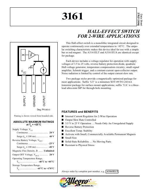
This Hall-effect switch is a monolithic integrated circuit designed to operate continuously over extended temperatures to +85°C. The unipo-lar switching characteristic makes this device ideal for use with a simple bar or rod magnet. The A3161ELT and A3161EUA are identical except for package.Each device includes a voltage regulator for operation with supply voltages of 3.5 to 25 volts, reverse battery protection diode, quadratic Hall-voltage generator, temperature compensation circuitry, small-signal amplifier, Schmitt trigger, and a constant-current open-collector output.Noise radiation is limited by control of the output current slew rate.Two package styles provide a magnetically optimized package for most applications. Suffix ‘LT’ is a miniature SOT-89/TO-243AAtransistor package for surface-mount applications; suffix ‘UA’ is a three-lead ultra-mini SIP for through-hole mounting.HALL-EFFECT SWITCH FOR 2-WIRE APPLICATIONSAlways order by complete part number, e.g., A3161ELT .Data Sheet 27621.30A‡FEATURES and BENEFITSI Internal Current Regulator for 2-Wire Operation I Output Slew Rate ControlledI 3.5 V to 25 V Operation … Needs Only An Unregulated Supply I Reverse Battery Protection I Excellent Temp. StabilityI Activate with Small, Commercially Available Permanent Magnets I Small SizeI Solid-State Reliability … No Moving Parts IResistant to Physical Stress31613161HALL-EFFECT SWITCHFOR 2-WIRE APPLICATIONS115 Northeast Cutoff, Box 15036Worcester, Massachusetts 01615-0036 (508) 853-5000ELECTRICAL CHARACTERISTICS over operating voltage and temperature ranges.Copyright © 1998, 1999, Allegro MicroSystems, Inc.3161HALL-EFFECT SWITCH FOR 2-WIRE APPLICATIONSSWITCH POINTSTOTAL SUPPLY CURRENTTYPICAL OPERATING CHARACTERISTICSOUTPUT SATURATION VOLTAGESAFE OPERATING AREA50100AMBIENT TEMPERATURE in °C-50Dwg. GH-044-1S W I T C H P O I N T i n G A U S S150200100501500-2525751250T O T A L S U P P L Y C U R R E N T (I O U T + I C C ) i n m A2015255075100AMBIENT TEMPERATURE in °C-50Dwg. GH-028-4125-251505.01025155AMBIENT TEMPERATURE in °CM A X I M U M C O N T I N U O U S S U P P L Y V O L T A G E i n V O L T SDwg. GH-068302010025********AMBIENT TEMPERATURE in °C800400-50Dwg. GH-029-3S A T U R A T I O N V O L T A G E i n m V-2510006002003161HALL-EFFECT SWITCHFOR 2-WIRE APPLICATIONS115 Northeast Cutoff, Box 15036Worcester, Massachusetts 01615-0036 (508) 853-5000OPERATIONThe output of these devices (pin 3) switches OFF when the magnetic field at the Hall sensor exceeds the operate point threshold (B OP ). When the magnetic field is reduced to below the release point threshold (B RP ), the device output switches ON. The difference in the magnetic operate and release points is called the hysteresis (B hys ) of the device. This built-in hysteresis allows clean switching of the output even in the presence of external mechanical vibration and electrical noise.APPLICATIONS INFORMATIONThese devices are normally operated in a 2-wire mode, where the supply terminal and the output terminal are tied together. An external comparator detects the change in total supply current by the addition (output off, B > B OP )or subtraction (output on, B < B RP ) of I OUT .Hall effect applications information is available in the “Hall-Effect IC Applications Guide”, which can be found in the latest issue of the Allegro MicroSystems Electronic Data Book , AMS-702 or Application Note 27701,or at .TYPICAL 2-WIRE APPLICATIONUT1001251501752003.00O U T P U T C U R R E N T i n m AMAGNETIC FLUX DENSITY in GAUSS129.06.075Dwg. GH-007-15025153161 HALL-EFFECT SWITCH FOR 2-WIRE APPLICATIONS PACKAGE DESIGNATOR ‘LT’Dimensions in Inches(for reference only)Dimensions in Millimeters(controlling dimensions)0.440.353161HALL-EFFECT SWITCHFOR 2-WIRE APPLICATIONS115 Northeast Cutoff, Box 15036Worcester, Massachusetts 01615-0036 (508) 853-5000PACKAGE DESIGNATOR ‘UA’Dimensions in Inches Dimensions in Millimeters(controlling dimensions)(for reference only)NOTES:1.Tolerances on package height and width represent allowable mold offsets.Dimensions given are measured at the widest point (parting line).2.Exact body and lead configuration at vendor’s option within limits shown.3.Height does not include mold gate flash.Dwg. MH-014E in0.050BSC°Dwg. MH-014E mm1.27BSC°0.480.363161 HALL-EFFECT SWITCH FOR 2-WIRE APPLICATIONSThe products described herein are manufactured under one or more of the following U.S. patents: 5,045,920; 5,264,783; 5,442,283;5,389,889; 5,581,179; 5,517,112; 5,619,137; 5,621,319; 5,650,719; 5,686,894; 5,694,038; 5,729,130; 5,917,320; and other patents pending.Allegro MicroSystems, Inc. reserves the right to make, from time to time, such departures from the detail specifications as may be required to permit improvements in the performance, reliability, or manufacturability of its products. Before placing an order, the user is cautioned to verify that the information being relied upon is current.Allegro products are not authorized for use as critical components in life-support appliances, devices, or systems without express written approval.The information included herein is believed to be accurate and reliable. However, Allegro MicroSystems, Inc. assumes no responsibil-ity for its use; nor for any infringements of patents or other rights of third parties that may result from its use.3161HALL-EFFECT SWITCHFOR 2-WIRE APPLICATIONS115 Northeast Cutoff, Box 15036Worcester, Massachusetts 01615-0036 (508) 853-5000HALL-EFFECT SENSORSPartial Part Avail. Oper.Characteristics at T A = +25°C Number Temp.B OP max B RP min B hys typ FeaturesNotesHALL-EFFECT UNIPOLAR SWITCHES in order of B OP and B hys 3240E/L +50+5.010chopper stabilized 13209E ±60±5.07.7400 µW, chopper stabilized 3210E ±60±5.07.725 µW, chopper stabilized 3361E +110+55 5.0*2-wire, chopper stabilized3362E +110+55 5.0*2-wire, chopper stabilized, inverted output 3161E +160+30202-wire3141E/L +160+10553235S +175+2515*output 12-25-17515*output 225140E +200+5055300 mA power driver output13142E/L +230+75553143E/L +340+165553144E/L +350+50553122E/L +400+1401053123E/L +440+1801053121E/L+450+125105HALL-EFFECT LATCHES & BIPOLAR SWITCHES †in order of B OP and B hys3260E/L +30-3020bipolar switch, chopper stabilized 3280E/L +40-4045chopper stabilized 3134E/L +50-5027bipolar switch 3133K/L/S +75-7552bipolar switch 3281E/L +90-90100chopper stabilized 3132K/L/S +95-9552bipolar switch 3187E/L +150-150100*3177S +150-1502003625S +150-150200900 mA power driver output 1, 33626S +150-150200400 mA power driver output 1, 33195E/L +160-160220active pulldown 13197L +160-16023013175S +170-1702003188E/L +180-180200*3283E/L +180-180300chopper stabilized 3189E/L +230-230100*3275S +250-250100*33185E/L +270-270340*Operating Temperature Ranges:S = -20°C to +85°C, E = -40°C to +85°C, J = -40°C to +115°C, K = -40°C to +125°C, L = -40°C to +150°C Notes 1.Protected.2.Output 1 switches on south pole, output 2 switches on north pole for 2-phase, bifilar-wound, unipolar-driven brushless dc motor control.plementary outputs for 2-phase bifilar-wound, unipolar-driven brushless dc motor control.*Minimum. ‡ Maximum†Latches will not switch on removal of magnetic field; bipolar switches may switch on removal of field but require field reversal for reliable operation over operating temperature range.。
ACA3216M4-300-T中文资料

9421_ACA(1/2)EMC ComponentsACA Series ACA3216, 5020 T ypesFerrite Beads SMD ArrayFEATURES• A single ACA series chip can be used to suppress noise on 3, 4,or 6 lines, depending on the selected part. This product is thus an excellent choice for EMC suppression at the I/O lines of compact electronic equipment, such as portables, which require high-density circuit configurations.•Two types are available: the M type for general signals and the H type for high-speed (high-frequency band) signals. This noise countermeasure is therefore applicable to various types of circuits.• A 3-line type is available specifically for audio applications, such as headphone lines.• A 4-line type with a 3216 form factor is available as a direct replacement for standard chip resistor arrays. It can be used without any change to the circuit board land pattern. APPLICATIONSNoise suppression for audio applications, including headphone lines in CD-ROM, DVD, MD, and other equipment (3-line type).Noise suppression for the I/O lines of notebook PCs, word proces-sors, digital TVs and VTRs, and portable communications equip-ment.ACA3216 TYPE (3- and 4-Line)SHAPES AND DIMENSIONS/CIRCUIT DIAGRAMS/RECOMMENDED PC BOARD PATTERNS (REFLOW SOLDERING) 3-LINE 4-LINEELECTRICAL CHARACTERISTICS∗ X:Packaging style (T: T aping [ø180mm reel], TL: T aping [ø330mm reel], B: Bulk)TYPICAL ELECTRICAL CHARACTERISTICS Z, X, R vs. FREQUENCY CHARACTERISTICSACA3216M4-600ACA3216H4-060ACA3216H4-120ACA3216H4-300YZER YHP4191APart No.Impedance ( Ω )[100MHz]DC resistance ( Ω )max.Rated current (mA)max.Pitch (mm)Built-in line number Voltage between lines Edc(V)max.ACA3216M3-600-X ∗600±25%0.851001 3 5ACA3216M4-060-X 60±25%0.43000.845ACA3216M4-120-X 120±25%12000.845ACA3216M4-300-X 300±25% 1.71000.8 4 5ACA3216M4-600-X600±25% 2.3600.8 4 5ACA3216H4-060-X 60±25%0.52500.845ACA3216H4-120-X 120±25%0.81500.845ACA3216H4-300-X300±25%1.71000.84 5元器件交易网9421_ACA 0104279421_ACA(2/2)EMC ComponentsACA Series ACA3216, 5020 T ypesFerrite Beads SMD ArrayACA5020 TYPE (6-Line)SHAPES AND DIMENSIONS/CIRCUIT DIAGRAM/RECOMMENDED PC BOARD PATTERN 6-LINEELECTRICAL CHARACTERISTICS∗ X:Packaging style (T: T aping [ø180mm reel], TL: [ø330mm reel], B: Bulk)TYPICAL ELECTRICAL CHARACTERISTICSZ, X, R vs. FREQUENCY CHARACTERISTICS ACA5020M6-060ACA5020M6-120ACA5020H6-060ACA5020H6-120• TEST EQUIPMENT: RF IMPEDANCE ANAL YZER YHP4191APart No.Impedance ( Ω )[100MHz]DC resistance ( Ω )max.Rated current (mA)max.Pitch (mm)Built-in line number Voltage between lines Edc(V)max.ACA5020M6-060-X ∗60±25%0.34000.8 6 5ACA5020M6-120-X 120±25%0.52000.865ACA5020H6-060-X 60±25%0.52500.8 6 5ACA5020H6-120-X120±25%0.81500.865元器件交易网。
SCM-2M3216-181中文资料

SCM-4□ seriesSCM-2□ seriesFeatures1. Effective for suppressing common mode noise at high frequencies.2. Compact design.3. Excellent solderability characteristics.4. Lead Free (RoHS Compliance)Applications1. Noise suppression in digital bus line equipment2. IEEE1394a HUB & IEEE1394a control lines.3. USB host controller & USB, HUB control lines4. LVDS, panel link line for liquid crystal display panels.Shape and DimensionsM : General Signal lineY,S: High speed differential signal line (6) Termination J : Nickel barrier(4) DimensionFirst two digits : length(mm) Last two digits : width(mm) (7) Packaging B : Bulk PackingT : Tape & Reel (Φ 178mm [ 7inches])L : Tape & Reel (Φ 254mm [10inches])unit : mm 〔inches 〕TypeLWTC 1C 2DM3.2±0.2 1.6±0.2 1.3±0.1 0.7±0.2 0.3±0.2 2.1±0.2 0.20±0.1SCM-2 3216- [.126±.008] [.063±.008] [.051±.004] [.028±.008] [.012±.008] [.083±.008] [.008±.004]3.2±0.2 1.6±0.2 1.3±0.1 0.4±0.2 0.3±0.20.80±0.1 0.20±0.1 SCM-4 3216-[.126±.008] [.063±.008] [.051±.004] [.016±.008] [.012±.008] [.031±.004] [.008±.004]1M 10M 100M 1G 1101001000N or m a l M o d e I m p e d a n c e C om m o n M o d e I m pe d a n c eCM-2(M/L)3216-900JI m p e d a n c e [o h m ]Frequency [ Hz ]1M 10M 100M 1G 1101001000N or m a l M o d e I mp e d a n c eC o m m o n M o d e I m p e d a n c eCM-2(M/L)3216-700JI m p e d a n c e [o h m ]Frequency [ Hz ]1M 10M 100M 1G 1101001000N or m a l M o d e I mp e d a n c e C o m m o n M o d e I m p e d a n c eCM-2(M/L)3216-181JI m p e d a n c e [o h m ]Frequency [ Hz ]1M 10M 100M 1G 1101001000N or m a l M o d e I m p e d a n c e C om m o n M od e I m p e d a n c eCM-2(M/L)3216-221JI m p e d a n c e [o h m ]Frequency [ Hz ]Electrical ParametersImpedance[Ω] at 100MK. Part No.TypToleranceDCResistance Max.(Ω)Rated current Max.(mA)Rated Voltage Max.(V)Insulation Resistance Min.(M Ω)SCM-2M3216-700□□ 70 0.50 400 16 100 SCM-2M3216-900□□ 90 0.55 400 16 100 SCM-2M3216-121□□ 120 0.60 400 16 100 SCM-2M3216-181□□ 180 0.65 330 16 100 SCM-2M3216-221□□ 220 0.70 330 16 100 SCM-2M3216-471□□ 470 0.80 250 16 100 SCM-4M3216-700□□ 70 0.60 400 10 100 SCM-4M3216-900□□ 90 0.70 400 10 100 SCM-4M3216-121□□ 120 0.80 400 10 100 SCM-4M3216-181□□ 180 0.90 330 10 100 SCM-4M3216-221□□ 220 0.90 330 10 100 SCM-4S3216-900□□ 90 0.70 400 10 100 SCM-4S3216-121□□ 120 0.80 400 10 100 SCM-4S3216-181□□ 180 1.0033010100SCM-4S3216-301□□ 300±25% 1.20 250 10 100Electrical Characteristic Curves3216 – 2Line (Single)1M 10M 100M 1G1101001000N or m a l M o d eI m p e d a n c eC o m m o n M o d e I m p e d a n c eCM-2(M/L)3216-121JI m p e d a n c e [o h m ]Frequency [ Hz ]1M 10M 100M 1G1101001000N or m a l M o d e I m p e d a n c e C om m o n M o d e I m p e d a n c eCM-2(M/L)3216-471JI m p e d a n c e [o h m ]Frequency [ Hz ]SCM-2M3216-700J SCM-2M3216-900J SCM-2M3216-121J SCM-2M3216-181J SCM-2M3216-221J SCM-2M3216-471J1M 10M 100M 1G1101001000N or m a l M o d e I m p e d a n c e C om m o n M o d e I m p e d a n c eCM-4(M/L)3216-221J I m p e d a n c e [o h m ]Frequency [ Hz ]1M 10M 100M 1G 1101001000N or m a l M o d e I mp e d a n c e C o m m o n M o d e I m p e d a n c eCM-4(M/L)3216-181J I m p e d a n c e [o h m ]Frequency [ Hz ]1M 10M 100M 1G1101001000N or m a l M o d e I m p e d a n ce C o m mo n M o d e I m p e d a n c eCM-4(M/L)3216-900J I m p e d a n c e [o h m ]Frequency [ Hz ]1M 10M 100M 1G1101001000N or m a l M o d e I m p e d a n c eC o m m o n M o d e Im pe d a n c eCM-4(M/L)3216-700J I m p e d a n c e [o h m ]Frequency [ Hz ]I m p e d a n c e [o h m ]Frequency [Hz]1101001000I m p e d a n c e [o h m ]Frequency [Hz]I m p e d a n c e [o h m ]Frequency [Hz]1M10M100M1G1101001000N or m a l m o d e I m p e d a n c eCo m m o n m o d e I m p e d a n c eCM-4S3216-301JTI m p e d a n c e [o h m ]Frequency [Hz]SCM-4S3216-900J3216 – 4Line (Double)3216 – 4Line (Double) – S type1M10M100M1G1101001000N or m a l M o d e I m p e d a n c e Co m m o n M o de I m p e d a n c eCM-4(M/L)3216-121J I m p e d a n c e [o h m ]Frequency [ Hz ]SCM-4M3216-700JSCM-4M3216-900JSCM-4M3216-121JSCM-4M3216-181JSCM-4M3216-221J10M100M 1G50100150200CM-4S3216-900JC h a r a ct e ri s t i c I m p e d a n c e [o h m ]Frequency[Hz]C h a r a c t e r i s t i c I m p e d a n c e [o h m ]Frequency[Hz]10M100M 1G050100150200CM-4S3216-181JC h a r a c t e r i s t i c I m p e d a n c e [o h m ]Frequency[Hz]10M100M 1G50100150200CM-4S3216-181JC h a r a c t e r i s t i c I m p e d a n c e [o h m ]Frequency[Hz]1M10M100M 1G-30-28-25-23-20-18-15-13-10-8-5-30N or m a l M o de C o m m o n M o d eCM-4S3216-900JI n s e r t i o n l o s s [d B ]Freqeuncy[Hz]I n s e r t i o n l o s s [d B ]Freqeuncy[Hz]I n s e r t i o n l o s s [d B ]Freqeuncy[Hz]Characteristic Impedance vs. Frequency characteristicsInsertion loss vs. Frequency CharacteristicsSCM-4S3216-900J SCM-4S3216-181J SCM-4S3216-301J SCM-4S3216-900J。
中文四版-SMC样本
20~40
CAT.C04-02A
20~40
CAT.C04-02A
40~100
CAT.C09-03A
32~125
CAT.C05-09B
32~100
CAT.C06-06A
125~300 8~25
CA3T2.C~05-2052B0
20~63 32~100
正确内容
32~100
CAT.C08-04B
12~100
07年8月 06年8月 06年8月 06年8月 06年8月 07年8月
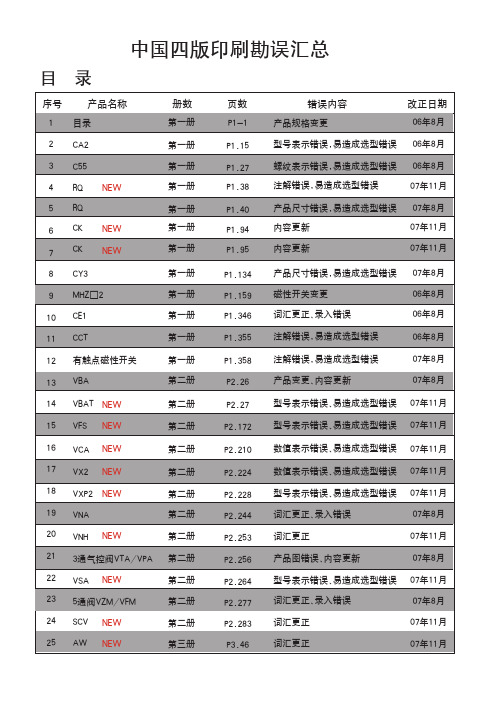
说明:1.中国四版06年1月份正式印刷完成,06年8月份第一次增印,改动10页,07年8月份第二次增印,改动15页, 07年11月第三次增印,改动18页。
2.请注意将将更改信息通知相关客户,订货时予以确认。
执行元件
系列
气缸类型
缸径(mm) 中文样本编号 英文样本编号 日文样本编号 页号
页数 P3.55 P4.25 P4.26
错误内容 可换件型号错误 数值表示错误 型号表示错误、易造成选型错误
P4.34 P4.42
词汇更正、录入错误 型号表示不清、易造成选型错误
P4.64 P4.70
词汇更正、录入错误 追加系列
P4.102 型号表示内容错误
P4.110 型号表示内容错误
P5.09 数值表示错误
标准型气缸
图形符号
CA2系列 ( ~ )
1
1
。
弯
1系列
1
。
。 。
。
型号表示方法
mm
拉杆安装
除A54外 仅A54 BT-04 BT-06 BT-08
参见P.1.357。
正确内容
F
APC-MGE UPS及机房设备选型
版本号:LIT-960-HBN-ITB002 © 2010 所有产品标识均属APC by Schneider Electric公司所有
目录
■ 公司简介........................................................................................................................... 04
桌面和移动设备
5
■ 关键电源设备-UPS和浪涌保护设备 ............................................................................... 78
(Back-UPS® / CS / RS , Surge Arrest®)
管理解决方案
(Smart-UPS® VT, MGE™ Galaxy™ 3000, Comet 3000 3:1 / 3:3, MGE™ Galaxy™ 3500 3:1 / 3:3, Symmetra® LX)
■ 服务器机房-机柜和UPS产品 .......................................................................................... 56
6 ■ 数据中心物理基础设施管理 .............................................................................................. 82 (英飞中央管理器,容量管理器和变更管理器) ■ UPS电源管理系统 ............................................................................................................ 84 ■ 电池管理系统.................................................................................................................... 86 (B2000 / CellWatch 电池监测系统, APC 蓄电池管理系统) ■ 精密空调监控系统 ............................................................................................................ 87 (C7000控制器) ■ 安全和环境监测解决方案.................................................................................................. 88 (NetBotz®)
NSSM016C中文资料

NSSM016C中⽂资料No. STSE-CM6044ASPECIFICATIONS FOR NICHIA CHIP TYPE FULL COLOR LEDMODEL : NSSM016CTNICHIA CORPORATION1.SPECIFICATIONS(1) Absolute Maximum Ratings (Ta=25°C)Absolute Maximum Rating Item Symbol Blue Green RedUnit Forward Current I F 35 35 50 mA Pulse Forward Current I FP 110 110 200 mA Reverse Voltage V R 5 V Power Dissipation P D 123 123 125 mW Total Power Dissipation P tot 280 mW Operating Temperature T opr -30 ~ + 85 °C Storage Temperature T stg -40 ~ +100 °C Soldering Temperature T sld Reflow Soldering : 260°C for 10sec.Hand Soldering : 350°C for 3sec.I FP Conditions : Pulse Width 10msec. and Duty 1/10 Value for one LED device (Single color).Value for total power dissipation when two and more devices are lit simultaneously.(2) Initial Electrical/Optical Characteristics (Ta=25°C)Blue Green Red Item Symbol Condition Typ.Max.Typ.Max. Typ. Max.UnitForward Voltage V FI F =20[mA] (3.2) 3.5 (3.2) 3.5 (2.1) 2.5 V Reverse Current I R V R = 5[V] - 50 - 50 - 50µA Luminous Intensity Iv I F =20[mA] (400)- (1200)- (700) - mcd x - I F =20[mA] 0.133- 0.189- 0.700 - - Chromaticity Coordinatey-I F =20[mA]0.075- 0.718- 0.299 - -Please refer to CIE 1931 chromaticity diagram.(3) Ranking(Ta=25°C)Blue Green Red Item Symbol Condition Min.Max.Min.Max. Min. Max.UnitLuminous IntensityIvI F =20[mA] 280 560 800 1600 380 1080mcdLuminous Intensity Measurement allowance is ± 10%.Color Ranks (I F =20mA, Ta=25°C)BlueRank Wx 0.139 0.129 0.113 0.1340.1450.152y 0.035 0.050 0.080 0.1050.0720.056GreenRank G0c x 0.166 0.136 0.176 0.2200.2370.201<= <=RedRRankx 0.674 0.648 0.677 0.708y 0.296 0.323 0.323 0.292Color Coordinates Measurement allowance is ± 0.01.2.INITIAL OPTICAL/ELECTRICAL CHARACTERISTICSPlease refer to figure’s page.3.OUTLINE DIMENSIONS AND MATERIALSPlease refer to figure’s page.Material as follows ; Package : Heat-Resistant PolymerPackage Upper Surface Color : BlackEncapsulating Resin : Epoxy Resin (Diffused)Electrodes: Ag Plating Copper Alloy4.PACKAGING· The LEDs are packed in cardboard boxes after taping.Please refer to figure’s page.The label on the minimum packing unit shows ; Part Number, Lot Number, Quantity· In order to protect the LEDs from mechanical shock, we pack them in cardboard boxes for transportation. · The LEDs may be damaged if the boxes are dropped or receive a strong impact against them,so precautions must be taken to prevent any damage.· The boxes are not water resistant and therefore must be kept away from water and moisture.· When the LEDs are transported, we recommend that you use the same packing method as Nichia.5.LOT NUMBERThe first six digits number shows lot number.The lot number is composed of the following characters;{ ¯¯¯¯{ - Year ( 5 for 2005, 6 for 2006 )- Month ( 1 for Jan., 9 for Sep., A for Oct., B for Nov. )¯¯¯¯ - Nichia's Product Number6.RELIABILITY(1) TEST ITEMS AND RESULTS Test ItemStandardTest MethodTest Conditions Note Number of DamagedResistance toSoldering Heat (Reflow Soldering) JEITA ED-4701300 301 Tsld=260°C, 10sec.(Pre treatment 30°C,70%,168hrs.) 2 times0/50Thermal Shock JEITA ED-4701300 307 0°C ~ 100°C 15sec. 15sec.100 cycles 0/50 Temperature CycleJEITA ED-4701100 105 -40°C ~ 25°C ~ 100°C ~ 25°C 30min. 5min. 30min. 5min. 100 cycles 0/50 Moisture Resistance Cyclic JEITA ED-4701200 203 25°C ~ 65°C ~ -10°C 90%RH 24hrs./1cycle 10 cycles 0/50 High Temperature Storage JEITA ED-4701200 201 Ta=100°C500hrs.0/50Temperature Humidity StorageJEITA ED-4701100 103 Ta=60°C, RH=90%500hrs. 0/50 Low Temperature Storage JEITA ED-4701200 202Ta=-40°C500hrs.0/50Steady State Operating LifeTa=25°C, B I F =13mA G I F =32mA R I F =21mA500hrs. 0/50Steady State Operating Life of High Humidity Heat60°C, RH=90%, B I F =8.5mA G I F =18mA R I F =14.5mA500hrs. 0/50Steady State Operating Life of Low TemperatureTa=-30°C,B I F =13mA G I F =32mA R I F =21mA500hrs. 0/50Value for one LED device (Single color).(2) CRITERIA FOR JUDGING DAMAGE (Value for one LED device (Single color).)Criteria for Judgement Item SymbolTest Conditions Min. Max. Forward Voltage V F B,G,R I F =20mA - U.S.L.*) 1.1 Reverse Current I R B,G,R V R =5V - U.S.L.*) 2.0 Luminous IntensityI VB,G,R I F =20mA L.S.L.**) 0.7 -*) U.S.L. : Upper Standard Level **) L.S.L. : Lower Standard Level7.CAUTIONS(1) Moisture Proof Package· When moisture is absorbed into the SMT package it may vaporize and expand during soldering.There is a possibility that this can cause exfoliation of the contacts and damage to the opticalcharacteristics of the LEDs. For this reason, the moisture proof package is used to keep moisture to a minimum in the package.· The moisture proof package is made of an aluminum moisture proof bag. A package ofa moisture absorbent material (silica gel) is inserted into the aluminum moisture proof bag.The silica gel changes its color from blue to pink as it absorbs moisture.(2) Storage· Storage ConditionsBefore opening the package :The LEDs should be kept at 30°C or less and 90%RH or less. The LEDs should be used within a year. When storing the LEDs, moisture proof packaging with absorbent material (silica gel) is recommended.After opening the package :The LEDs should be kept at 30°C or less and 70%RH or less. The LEDs should be solderedwithin 168 hours (7days) after opening the package. If unused LEDs remain, they should bestored in moisture proof packages, such as sealed containers with packages of moisture absorbent material (silica gel). It is also recommended to return the LEDs to the original moisture proof bag and to reseal the moisture proof bag again.· If the moisture absorbent material (silica gel) has faded away or the LEDs have exceeded the storage time, baking treatment should be performed using the following conditions.Baking treatment : more than 24 hours at 65 ± 5°C· Nichia LED electrodes are silver plated copper alloy. The silver surface may be affected byenvironments which contain corrosive substances. Please avoid conditions which may cause the LED to corrode, tarnish or discolor. This corrosion or discoloration may cause difficulty during soldering operations. It is recommended that the User use the LEDs as soon as possible.· Please avoid rapid transitions in ambient temperature, especially in high humidity environments where condensation can occur.(3) Heat Generation· Thermal design of the end product is of paramount importance. Please consider the heat generation of the LED when making the system design. The coefficient of temperature increase per inputelectric power is affected by the thermal resistance of the circuit board and density of LED placement on the board, as well as other components. It is necessary to avoid intense heat generation and operate within the maximum ratings given in this specification.· During operation of the LEDs the total power dissipation of the diode elements (red, green, and blue) within the LEDs must not exceed the maximum power dissipation.· The operating current should be decided after considering the ambient maximum temperature of LEDs.120sec.Max.Pre-heating 260°C Max.10sec. Max. 60sec.Max. Above 220°C 1 ~ 5°C / sec. 1 ~ 5°C / sec. 180 ~ 200°C <1 : Lead Solder> <2 : Lead-free Solder> Pre-heating 240°C Max.10sec. Max. 60sec.Max. Above 200°C2.5 ~ 5°C / sec.2.5 ~ 5°C / sec. 120 ~ 150°C 120sec.Max. Nichia STSE-CM6044A-1(4) Soldering Conditions· The LEDs can be soldered in place using the reflow soldering method. Nichia cannot make a guarantee on the LEDs after they have been assembled using the dip soldering method. · Recommended soldering conditionsReflow SolderingHand SolderingLead Solder Lead-free Solder Pre-heat Pre-heat time Peak temperature Soldering time Condition 120 ~ 150°C 120 sec. Max. 240°C Max. 10 sec. Max. refer to Temperature - profile 1. 180 ~ 200°C 120 sec. Max. 260°C Max. 10 sec. Max. refer to Temperature - profile 2.(N 2 reflow is recommended.)Temperature Soldering time 350°C Max. 3 sec. Max. (one time only)Although the recommended soldering conditions are specified in the above table, reflow or handsoldering at the lowest possible temperature is desirable for the LEDs.A rapid-rate process is not recommended for cooling the LEDs down from the peak temperature. [Temperature-profile (Surface of circuit board)] Use the conditions shown to the under figure.[Recommended soldering pad design] Use the following conditions shown in the figure.· Occasionally there is a brightness decrease caused by the influence of heat or ambient atmosphere during air reflow. It is recommended that the User use the nitrogen reflow method.· Repairing should not be done after the LEDs have been soldered. When repairing is unavoidable, a double-head soldering iron should be used. It should be confirmed beforehand whether the characteristics of the LEDs will or will not be damaged by repairing. · Reflow soldering should not be done more than two times. · When soldering, do not put stress on the LEDs during heating. · After soldering, do not warp the circuit board.(5) Cleaning· It is recommended that isopropyl alcohol be used as a solvent for cleaning the LEDs. When using other solvents, it should be confirmed beforehand whether the solvents will dissolve the package and the resin or not. Freon solvents should not be used to clean the LEDs because of worldwide regulations. · Do not clean the LEDs by the ultrasonic. When it is absolutely necessary, the influence of ultrasonic cleaning on the LEDs depends on factors such as ultrasonic power and the assembled condition. (Unit : mm)2.7538.751.731.71.45.6Nichia STSE-CM6044A-1(6) Static Electricity· Static electricity or surge voltage damages the Blue/Green LEDs.It is recommended that a wrist band or an anti-electrostatic glove be used when handling the LEDs.· All devices, equipment and machinery must be properly grounded. It is recommended that precautions be taken against surge voltage to the equipment that mounts the LEDs.· When inspecting the final products in which LEDs were assembled, it is recommended to checkwhether the assembled LEDs are damaged by static electricity or not. It is easy to findstatic-damaged LEDs by a light-on test or a VF test at a lower current (below 1mA is recommended). · Damaged LEDs will show some unusual characteristics such as the leak current remarkablyincreases, the forward voltage becomes lower, or the LEDs do not light at the low current.Criteria : (V F> 2.0V at I F=0.5mA)(7) Others· NSSM016C complies with RoHS Directive.· Care must be taken to ensure that the reverse voltage will not exceed the absolute maximum ratingwhen using the LEDs with matrix drive.· The LED light output is strong enough to injure human eyes. Precautions must be taken to prevent looking directly at the LEDs with unaided eyes for more than a few seconds.· Flashing lights have been known to cause discomfort in people; you can prevent this by takingprecautions during use. Also, people should be cautious when using equipment that has had LEDsincorporated into it.· The LEDs described in this brochure are intended to be used for ordinary electronic equipment (such as office equipment, communications equipment, measurement instruments and household appliances).Consult Nichia’s sales staff in advance for information on the applications in which exceptional quality and reliability are required, particularly when the failure or malfunction of the LEDs may directlyjeopardize life or health (such as for airplanes, aerospace, submersible repeaters, nuclear reactorcontrol systems, automobiles, traffic control equipment, life support systems and safety devices).· User shall not reverse engineer by disassembling or analysis of the LEDs without having prior written consent from Nichia. When defective LEDs are found, the User shall inform Nichia directly beforedisassembling or analysis.· The formal specifications must be exchanged and signed by both parties before large volume purchase begins. · The appearance and specifications of the product may be modified for improvement without notice.Nic hia STSE-CM 6044AColor Coordinates Measurement allowance is ± 0.01.元器件交易⽹/doc/c486e8d17f1922791688e8a3.htmlNichiaSTSE-CM6044ANichiaSTSE-CM6044A-2Nichia STSE-CM6044A-11-Nichia STSE-CM6044A元器件交易⽹/doc/c486e8d17f1922791688e8a3.html Nichia STSE-CM6044A。
CD0中文手册
激光器标签,后面板
序列号标签,后面板 CE 标签,后面板
警告:为120伏电压进行的设
置
如需使用其他线路电压进行操作时,请参阅操作手册中的详细说明。
PN 9230003
电压标签,后面板
小心:除非采取了相应的保护措施,否则不要处理溶液容器。
有关安装程序请参阅操作人员手册。
PN 9230334
溶液容器标签,后面板
注意:在本手册中这些标签多用图形形式表示。
如何使用本手册
概述
本操作手册对使用与维护CELL-DYN 3200系统进行了完整的说明。
本手册的目的是为了满足下列需要:从对操作过程进行逐一说明,到辅件编号的列表。
在您学习使用本系统时,本手册会为您提供很大的帮助,在以后的使用过程中也会为您提供实质性的参考。
1级激光器产品
PN 9230702。
CTU样本

CTU空气断路器和负荷开关产品目录施耐德电气善用其效尽享其能全球能效管理专家施耐德电气为世界100多个国家提供整体解决方案,其中在能源与基础设施、工业过程控制、楼宇自动化和数据中心与网络等市场处于世界领先地位,在住宅应用领域也拥有强大的市场能力。
致力于为客户提供安全、可靠、高效的能源,施耐德电气2011年的销售额为224亿欧元,拥有超过130,000名员工。
施耐德电气助您——善用其效,尽享其能!施耐德电气在中国1987年,施耐德电气在天津成立第一家合资工厂梅兰日兰,将断路器技术带到中国,取代传统保险丝,使得中国用户用电安全性大为增强,并为断路器标准的建立作出了卓越的贡献。
90年代初,施耐德电气旗下品牌奇胜率先将开关面板带入中国,结束了中国使用灯绳开关的时代。
施耐德电气的高额投资有力地支持了中国的经济建设,并为中国客户提供了先进的产品支持和完善的技术服务,中低压电器、变频器、接触器等工业产品大量运用在中国国内的经济建设中,促进了中国工业化的进程。
目前,施耐德电气在中国共建立了53个办事处,28家工厂,7个物流中心,1个研修学院,3个研发中心,1个实验室,700多家分销商和遍布全国的销售网络。
施耐德电气中国目前员工数近28,000人。
通过与合作伙伴以及大量经销商的合作,施耐德电气为中国创造了成千上万个就业机会。
施耐德电气能效管理平台凭借其对五大市场的深刻了解、对集团客户的悉心关爱,以及在能效管理领域的丰富经验,施耐德电气从一个优秀的产品和设备供应商逐步成长为整体解决方案提供商。
今年,施耐德电气首次集成其在建筑楼宇、IT、安防、电力及工业过程和设备等五大领域的专业技术和经验,将其高质量的产品和解决方案融合在一个统一的架构下,通过标准的界面为各行业客户提供一个开放、透明、节能、高效的能效管理平台,为企业客户节省高达30%的投资成本和运营成本。
转变p为了更好的改变带给电力生活前所未有的高效无忧目录概述 (6)功能和特性 (12)推荐安装方式 (35)尺寸和连接 (46)电路图 (61)附加特性 (66)选型指南 (68)相关产品简介 (81)随着我国供电系统的发展,从住宅小区配电间、箱式变电站,到输变电站和城农网改造,现代配电网络正发生着变化:供电网络规模不断扩大;配电系统保护日益复杂;供电可靠性、连续性要求不断提高;电力管理难度更大;用户的需求不断从电力供给转向电力服务……CTU系列低压断路器,为输配电系统量身定做,全面满足上述供电系统需求:●秉承施耐德电气一贯出色品质,经典的高可靠、免维护、高环境适应性设计!●零飞弧、完善锁定、双重绝缘、人性化操作,提供最高等级的安全!●经典的保护功能和基础的测量功能,实现最简约的选择!CTU系列低压断路器基于供配电客户需求进行全新设计,引领先进供电系统应用理念:●两进线一母联自动投切系统,实现低压系统智能切换!●独特合环控制功能,避免线路切换产生停电或晃电!●全新环保设计,贯穿产品寿命每一阶段!转变,为更可靠、更高效、更智能的配电网络应用而改变,我们为现在和将来而设想:现代供配电网络——能否通过优化电网管理,使系统运行维护更加便捷、高效;能否通过完备应用,带给用户更多价值、服务!高标准的环境适应性CTU系列低压断路器所具备的高环境适应能力,可以保障配电系统在剧烈环Array境变化或严酷环境条件下依然稳定运行,例如建筑领域常用的箱式变电站,无空调环境的地下配电室,或空间狭小的安装环境。
常用开关电源芯片大全之欧阳育创编

常用开关电源芯片大全第1章DC-DC电源转换器/基准电压源1.1 DC-DC电源转换器1.低噪声电荷泵DC-DC电源转换器AAT3113/AAT31142.低功耗开关型DC-DC电源转换器ADP30003.高效3A开关稳压器AP15014.高效率无电感DC-DC电源转换器FAN56605.小功率极性反转电源转换器ICL76606.高效率DC-DC电源转换控制器IRU30377.高性能降压式DC-DC电源转换器ISL64208.单片降压式开关稳压器L49609.大功率开关稳压器L4970A10.1.5A降压式开关稳压器L497111.2A高效率单片开关稳压器L497812.1A高效率升压/降压式DC-DC电源转换器L597013.1.5A降压式DC-DC电源转换器LM157214.高效率1A降压单片开关稳压器LM1575/LM2575/LM2575HV15.3A降压单片开关稳压器LM2576/LM2576HV16.可调升压开关稳压器LM257717.3A降压开关稳压器LM259618.高效率5A开关稳压器LM267819.升压式DC-DC电源转换器LM2703/LM270420.电流模式升压式电源转换器LM273321.低噪声升压式电源转换器LM275022.小型75V降压式稳压器LM500723.低功耗升/降压式DC-DC电源转换器LT107324.升压式DC-DC电源转换器LT161525.隔离式开关稳压器LT172526.低功耗升压电荷泵LT175127.大电流高频降压式DC-DC电源转换器LT176528.大电流升压转换器LT193529.高效升压式电荷泵LT193730.高压输入降压式电源转换器LT195631.1.5A升压式电源转换器LT196132.高压升/降压式电源转换器LT343333.单片3A升压式DC-DC电源转换器LT343634.通用升压式DC-DC电源转换器LT346035.高效率低功耗升压式电源转换器LT346436.1.1A升压式DC-DC电源转换器LT346737.大电流高效率升压式DC-DC电源转换器LT378238.微型低功耗电源转换器LTC175439.1.5A单片同步降压式稳压器LTC187540.低噪声高效率降压式电荷泵LTC191141.低噪声电荷泵LTC3200/LTC3200-542.无电感的降压式DC-DC电源转换器LTC325143.双输出/低噪声/降压式电荷泵LTC325244.同步整流/升压式DC-DC电源转换器LTC340145.低功耗同步整流升压式DC-DC电源转换器LTC340246.同步整流降压式DC-DC电源转换器LTC340547.双路同步降压式DC-DC电源转换器LTC340748.高效率同步降压式DC-DC电源转换器LTC341649.微型2A升压式DC-DC电源转换器LTC342650.2A两相电流升压式DC-DC电源转换器LTC342851.单电感升/降压式DC-DC电源转换器LTC344052.大电流升/降压式DC-DC电源转换器LTC344253.1.4A同步升压式DC-DC电源转换器LTC345854.直流同步降压式DC-DC电源转换器LTC370355.双输出降压式同步DC-DC电源转换控制器LTC373656.降压式同步DC-DC电源转换控制器LTC377057.双2相DC-DC电源同步控制器LTC380258.高性能升压式DC-DC电源转换器MAX1513/MAX151459.精简型升压式DC-DC电源转换器MAX1522/MAX1523/MAX152460.高效率40V升压式DC-DC电源转换器MAX1553/MAX155461.高效率升压式LED电压调节器MAX1561/MAX159962.高效率5路输出DC-DC电源转换器MAX156563.双输出升压式DC-DC电源转换器MAX1582/MAX1582Y64.驱动白光LED的升压式DC-DC电源转换器MAX158365.高效率升压式DC-DC电源转换器MAX1642/MAX164366.2A降压式开关稳压器MAX164467.高效率升压式DC-DC电源转换器MAX1674/MAX1675/MAX167668.高效率双输出DC-DC电源转换器MAX167769.低噪声1A降压式DC-DC电源转换器MAX1684/MAX168570.高效率升压式DC-DC电源转换器MAX169871.高效率双输出降压式DC-DC电源转换器MAX171572.小体积升压式DC-DC电源转换器MAX1722/MAX1723/MAX172473.输出电流为50mA的降压式电荷泵MAX173074.升/降压式电荷泵MAX175975.高效率多路输出DC-DC电源转换器MAX180076.3A同步整流降压式稳压型MAX1830/MAX183177.双输出开关式LCD电源控制器MAX187878.电流模式升压式DC-DC电源转换器MAX189679.具有复位功能的升压式DC-DC电源转换器MAX194780.高效率PWM降压式稳压器MAX1992/MAX199381.大电流输出升压式DC-DC电源转换器MAX61882.低功耗升压或降压式DC-DC电源转换器MAX62983.PWM升压式DC-DC电源转换器MAX668/MAX66984.大电流PWM降压式开关稳压器MAX724/MAX72685.高效率升压式DC-DC电源转换器MAX756/MAX75786.高效率大电流DC-DC电源转换器MAX761/MAX76287.隔离式DC-DC电源转换器MAX8515/MAX8515A88.高性能24V升压式DC-DC电源转换器MAX872789.升/降压式DC-DC电源转换器MC33063A/MC34063A90.5A升压/降压/反向DC-DC电源转换器MC33167/MC3416791.低噪声无电感电荷泵MCP1252/MCP125392.高频脉宽调制降压稳压器MIC220393.大功率DC-DC升压电源转换器MIC229594.单片微型高压开关稳压器NCP1030/NCP103195.低功耗升压式DC-DC电源转换器NCP1400A96.高压DC-DC电源转换器NCP140397.单片微功率高频升压式DC-DC电源转换器NCP141098.同步整流PFM步进式DC-DC电源转换器NCP142199.高效率大电流开关电压调整器NCP1442/NCP1443/NCP1444/NCP1445100.新型双模式开关稳压器NCP1501101.高效率大电流输出DC-DC电源转换器NCP1550102.同步降压式DC-DC电源转换器NCP1570103.高效率升压式DC-DC电源转换器NCP5008/NCP5009 104.大电流高速稳压器RT9173/RT9173A105.高效率升压式DC-DC电源转换器RT9262/RT9262A106.升压式DC-DC电源转换器SP6644/SP6645107.低功耗升压式DC-DC电源转换器SP6691108.新型高效率DC-DC电源转换器TPS54350109.无电感降压式电荷泵TPS6050x110.高效率升压式电源转换器TPS6101x111.28V恒流白色LED驱动器TPS61042112.具有LDO输出的升压式DC-DC电源转换器TPS6112x 113.低噪声同步降压式DC-DC电源转换器TPS6200x114.三路高效率大功率DC-DC电源转换器TPS75003115.高效率DC-DC电源转换器UCC39421/UCC39422116.PWM控制升压式DC-DC电源转换器XC6371117.白光LED驱动专用DC-DC电源转换器XC9116118.500mA同步整流降压式DC-DC电源转换器XC9215/XC9216/XC9217119.稳压输出电荷泵XC9801/XC9802120.高效率升压式电源转换器ZXLB16001.2 线性/低压差稳压器121.具有可关断功能的多端稳压器BAXXX122.高压线性稳压器HIP5600123.多路输出稳压器KA7630/KA7631124.三端低压差稳压器LM2937125.可调输出低压差稳压器LM2991126.三端可调稳压器LM117/LM317127.低压降CMOS500mA线性稳压器LP38691/LP38693128.输入电压从12V到450V的可调线性稳压器LR8129.300mA非常低压降稳压器(VLDO)LTC3025130.大电流低压差线性稳压器LX8610131.200mA负输出低压差线性稳压器MAX1735132.150mA低压差线性稳压器MAX8875133.带开关控制的低压差稳压器MC33375134.带有线性调节器的稳压器MC33998135.1.0A低压差固定及可调正稳压器NCP1117136.低静态电流低压差稳压器NCP562/NCP563137.具有使能控制功能的多端稳压器PQxx138.五端可调稳压器SI-3025B/SI-3157B139.400mA低压差线性稳压器SPX2975140.五端线性稳压器STR20xx141.五端线性稳压器STR90xx142.具有复位信号输出的双路输出稳压器TDA8133143.具有复位信号输出的双路输出稳压器TDA8138/TDA8138A144.带线性稳压器的升压式电源转换器TPS6110x145.低功耗50mA低压降线性稳压器TPS760xx146.高输入电压低压差线性稳压器XC6202147.高速低压差线性稳压器XC6204148.高速低压差线性稳压器XC6209F149.双路高速低压差线性稳压器XC64011.3 基准电压源150.新型XFET基准电压源ADR290/ADR291/ADR292/ADR293151.低功耗低压差大输出电流基准电压源MAX610x152.低功耗1.2V基准电压源MAX6120153.2.5V精密基准电压源MC1403154.2.5V/4.096V基准电压源MCP1525/MCP1541155.低功耗精密低压降基准电压源REF30xx/REF31xx156.精密基准电压源TL431/KA431/TLV431A第2章AC-DC转换器及控制器1.厚膜开关电源控制器DP104C2.厚膜开关电源控制器DP308P3.DPA-Switch系列高电压功率转换控制器DPA423/DPA424/DPA425/DPA4264.电流型开关电源控制器FA13842/FA13843/FA13844/FA138455.开关电源控制器FA5310/FA53116.PWM开关电源控制器FAN75567.绿色环保的PWM开关电源控制器FAN76018.FPS型开关电源控制器FS6M07652R9.开关电源功率转换器FS6Sxx10.降压型单片AC-DC转换器HV-2405E11.新型反激准谐振变换控制器ICE1QS0112.PWM电源功率转换器KA1M088013.开关电源功率转换器KA2S0680/KA2S088014.电流型开关电源控制器KA38xx15.FPS型开关电源功率转换器KA5H0165R16.FPS型开关电源功率转换器KA5Qxx17.FPS型开关电源功率转换器KA5Sxx18.电流型高速PWM控制器L499019.具有待机功能的PWM初级控制器L599120.低功耗离线式开关电源控制器L659021.LINK SWITCH TN系列电源功率转换器LNK304/LNK305/LNK30622.LINK SWITCH系列电源功率转换器LNK500/LNK501/LNK52023.离线式开关电源控制器M51995A24.PWM电源控制器M62281P/M62281FP25.高频率电流模式PWM控制器MAX5021/MAX502226.新型PWM开关电源控制器MC4460427.电流模式开关电源控制器MC4460528.低功耗开关电源控制器MC4460829.具有PFC功能的PWM电源控制器ML482430.液晶显示器背光灯电源控制器ML487631.离线式电流模式控制器NCP120032.电流模式脉宽调制控制器NCP120533.准谐振式PWM控制器NCP120734.低成本离线式开关电源控制电路NCP121535.低待机能耗开关电源PWM控制器NCP123036.STR系列自动电压切换控制开关STR8xxxx37.大功率厚膜开关电源功率转换器STR-F665438.大功率厚膜开关电源功率转换器STR-G865639.开关电源功率转换器STR-M6511/STR-M652940.离线式开关电源功率转换器STR-S5703/STR-S5707/STR-S570841.离线式开关电源功率转换器STR-S6401/STR-S6401F/STR-S6411/STR-S6411F 442.开关电源功率转换器STR-S651343.离线式开关电源功率转换器TC33369~TC3337444.高性能PFC与PWM组合控制集成电路TDA16846/TDA1684745.新型开关电源控制器TDA1685046.“绿色”电源控制器TEA150447.第二代“绿色”电源控制器TEA150748.新型低功耗“绿色”电源控制器TEA153349.开关电源控制器TL494/KA7500/MB375950.Tiny SwitchⅠ系列功率转换器TNY253、TNY254、TNY25551.Tiny SwitchⅡ系列功率转换器TNY264P~TNY268G52.TOP Switch(Ⅱ)系列离线式功率转换器TOP209~TOP22753.TOP Switch-FX系列功率转换器TOP232/TOP233/TOP23454.TOP Switch-GX系列功率转换器TOP242~TOP25055.开关电源控制器UCX84X56.离线式开关电源功率转换器VIPer12AS/VIPer12ADIP57.新一代高度集成离线式开关电源功率转换器VIPer53第3章功率因数校正控制/节能灯电源控制器1.电子镇流器专用驱动电路BL83012.零电压开关功率因数控制器FAN48223.功率因数校正控制器FAN75274.高电压型EL背光驱动器HV8265.EL场致发光背光驱动器IMP525/IMP5606.高电压型EL背光驱动器/反相器IMP8037.电子镇流器自振荡半桥驱动器IR21568.单片荧光灯镇流器IR21579.调光电子镇流器自振荡半桥驱动器IR215910.卤素灯电子变压器智能控制电路IR216111.具有功率因数校正电路的镇流器电路IR216612.单片荧光灯镇流器IR216713.自适应电子镇流器控制器IR252014.电子镇流器专用控制器KA754115.功率因数校正控制器L656116.过渡模式功率因数校正控制器L656217.集成背景光控制器MAX8709/MAX8709A18.功率因数校正控制器MC33262/MC3426219.固定频率电流模式功率因数校正控制器NCP165320.EL场致发光灯高压驱动器SP440321.功率因数校正控制器TDA4862/TDA486322.有源功率因数校正控制器UC385423.高频自振荡节能灯驱动器电路VK05CFL24.大功率高频自振荡节能灯驱动器电路VK06TL第4章充电控制器1.多功能锂电池线性充电控制器AAT36802.可编程快速电池充电控制器BQ20003.可进行充电速率补偿的锂电池充电管理器BQ20574.锂电池充电管理电路BQ2400x5.单片锂电池线性充电控制器BQ2401xB接口单节锂电池充电控制器BQ2402x7.2A同步开关模式锂电池充电控制器BQ241008.集成PWM开关控制器的快速充电管理器BQ29549.具有电池电量计量功能的充电控制器DS277010.锂电池充电控制器FAN7563/FAN756411.2A线性锂/锂聚合物电池充电控制器ISL629212.锂电池充电控制器LA5621M/LA5621V13.1.5A通用充电控制器LT157114.2A恒流/恒压电池充电控制器LT176915.线性锂电池充电控制器LTC173216.带热调节功能的1A线性锂电池充电控制器LTC173317.线性锂电池充电控制器LTC173418.新型开关电源充电控制器LTC198019.开关模式锂电池充电控制器LTC400220.4A锂电池充电器LTC400621.多用途恒压/恒流充电控制器LTC400822.4.2V锂离子/锂聚合物电池充电控制器LTC405223.可由USB端口供电的锂电池充电控制器LTC405324.小型150mA锂电池充电控制器LTC405425.线性锂电池充电控制器LTC405826.单节锂电池线性充电控制器LTC405927.独立线性锂电池充电控制器LTC406128.镍镉/镍氢电池充电控制器M62256FP29.大电流锂/镍镉/镍氢电池充电控制器MAX150130.锂电池线性充电控制器MAX150731.双输入单节锂电池充电控制器MAX1551/MAX155532.单节锂电池充电控制器MAX167933.小体积锂电池充电控制器MAX1736B接口单节锂电池充电控制器MAX181135.多节锂电池充电控制器MAX187336.双路输入锂电池充电控制器MAX187437.单节锂电池线性充电控制器MAX189838.低成本/多种电池充电控制器MAX190839.开关模式单节锂电池充电控制器MAX1925/MAX192640.快速镍镉/镍氢充电控制器MAX2003A/MAX200341.可编程快速充电控制器MAX712/MAX71342.开关式锂电池充电控制器MAX74543.多功能低成本充电控制器MAX846A44.具有温度调节功能的单节锂电池充电控制器MAX8600/MAX860145.锂电池充电控制器MCP73826/MCP73827/MCP7382846.高精度恒压/恒流充电器控制器MCP73841/MCP73842/MCP73843/MCP73844 647.锂电池充电控制器MCP73861/MCP7386248.单节锂电池充电控制器MIC7905049.单节锂电池充电控制器NCP180050.高精度线性锂电池充电控制器VM7205。
PD80F01x系列_中文资料_数据手册
Rev1.20
第1页
2020-7-27
Pdmicro Technology Ltd
PD80F01X
目录
特性..................................................................................................................................................................................1
2.1. 地址映射................................................................................................................................................................. 9 2.1.1. SFR,BANK0................................................................................................................................................. 9 2.1.2. SFR,BANK1............................................................................................................................................... 10 2.1.3. TMR0,地址 0x01........
伊莱克斯电磁阀说明书
外 形 尺 寸 OV E R ALL DIM E N S IO N S (m m )
FG6 Rp 2"
56
2/ 6 208 128 182 2000 330
C
GAS FLOW CHART (PRESSURE DROP)
A C
B B
A
Description The VMR type is a fast opening and fast closing solenoid valve that is normally closed. When not energized the spring works on the seat keeping the gas passage closed. When the coil is powered the valve is rapidly opened.If the power supply is shut off,the valve rapidly closed.
FLOW FACTOR
KVS(m 3/h)
VM R 01--OT N VM R 02--OT N VM R 12--OT N
VMR0 VM R 12-A
VMR1 VMR2 VMR3 VM R35 VMR4 VMR6 VM R4F VM R6F VMR7 VMR8 VMR9 VM R93 VM R95
-
-
2.50
C3216C0G2J121K中文资料

For Mid Voltage SMDFEATURES•The unique design structure for mid voltage enables a compact size with high voltage resistance.•Rated voltage Edc: 100, 250 and 630V.•C3225, C4532 and C5750 types are specific to reflow soldering. APPLICATIONSSnapper circuits for switching power supply, ringer circuits for tele-phone and modem, or other general high voltage circuits.Dimensions in mm PRODUCT IDENTIFICATION(1) Series name(2) Dimensions(3) Capacitance temperature characteristicsClass 1 (Temperature compensation)Class 2 (Temperature stable and general purpose)(4) Rated voltage Edc(5) Nominal capacitanceThe capacitance is expressed in three digit codes and in units of pico farads (pF).The first and second digits identify the first and second significant figures of the capacitance.The third digit identifies the multiplier.R designates a decimal point.(6) Capacitance tolerance(7) Packaging styleType L W TC1608 1.6±0.10.8±0.10.8±0.1 C2012 2.0±0.2 1.25±0.20.6±0.10.85±0.151.25±0.2 C3216 3.2±0.2 1.6±0.20.6±0.10.85±0.151.15±0.151.3±0.21.6±0.2 C3225 3.2±0.42.5±0.3 1.25±0.21.6±0.22.0±0.2 C4532 4.5±0.43.2±0.4 1.6±0.22.0±0.22.3±0.22.5±0.33.2±0.4 C5750 5.7±0.4 5.0±0.4 1.6±0.22.3±0.21608 1.6×0.8mm2012 2.0×1.25mm3216 3.2×1.6mm3225 3.2×2.5mm4532 4.5×3.2mm5750 5.7×5.0mmcharacteristicsCapacitance change Temperature range C0G0±30ppm/°C–55 to +125°CTemperaturecharacteristicsCapacitance change Temperature range X7R±15%–55 to +125°C2A100V2E250V2J630V1021000pF33333000pF474470000pFJ±5%K±10%M±20%T Taping (reel)B BulkC2012JB2E102K(1)(2)(3)(4)(5)(6)(7)For Mid Voltage SMDC1608 (EIA:CC0603) TYPECAPACITANCE RANGES:CLASS 1 (TEMPERATURE COMPENSATION) TEMPERATURE CHARACTERISTICS: C0G(0±30ppm/°C) RATED VOLTAGE Edc: 250VRATED VOLTAGE Edc: 100V CAPACITANCE RANGES:CLASS 2TEMPERATURE CHARACTERISTICS: X7R(±15%) RATED VOLTAGE Edc:100VCapacitance (pF)ToleranceThickness(mm)Part No.100±10%0.8±0.1C1608C0G2E101K 120±5%0.8±0.1C1608C0G2E121J 150±10%0.8±0.1C1608C0G2E151K 180220±5%0.8±0.1C1608C0G2E221J ±10%0.8±0.1C1608C0G2E221K270±10%0.8±0.1C1608C0G2E271K 330±5%0.8±0.1C1608C0G2E331J 390±10%0.8±0.1C1608C0G2E391K 470560±5%0.8±0.1C1608C0G2E561J ±10%0.8±0.1C1608C0G2E561K680±10%0.8±0.1C1608C0G2E681KCapacitance (pF)ToleranceThickness(mm)Part No.100±5%0.8±0.1C1608C0G2A101J120±10%0.8±0.1C1608C0G2A121K150180±5%0.8±0.1C1608C0G2A181J ±10%0.8±0.1C1608C0G2A181K220±10%0.8±0.1C1608C0G2A221K 270±5%0.8±0.1C1608C0G2A271J330±10%0.8±0.1C1608C0G2A331K390470±5%0.8±0.1C1608C0G2A471J ±10%0.8±0.1C1608C0G2A471K560±10%0.8±0.1C1608C0G2A561K 680±5%0.8±0.1C1608C0G2A681J1000±10%0.8±0.1C1608C0G2A102K1200Capacitance(pF)ToleranceThickness(mm)Part No.1000±10%0.8±0.1C1608X7R2A102K±20%0.8±0.1C1608X7R2A102M1500±10%0.8±0.1C1608X7R2A152K±20%0.8±0.1C1608X7R2A152M2200±10%0.8±0.1C1608X7R2A222K±20%0.8±0.1C1608X7R2A222M3300±10%0.8±0.1C1608X7R2A332K±20%0.8±0.1C1608X7R2A332M4700±10%0.8±0.1C1608X7R2A472K±20%0.8±0.1C1608X7R2A472M6800±10%0.8±0.1C1608X7R2A682K±20%0.8±0.1C1608X7R2A682M10000±10%0.8±0.1C1608X7R2A103K±20%0.8±0.1C1608X7R2A103M∗M tolerance is standard for Mid Voltage X7R capacitors.•For more information about products with other capacitance or other data,For Mid Voltage SMDC2012 (EIA:CC0805) TYPECAPACITANCE RANGES:CLASS 1 (TEMPERATURE COMPENSATION) TEMPERATURE CHARACTERISTICS: C0G(0±30ppm/°C) RATED VOLTAGE Edc: 250VRATED VOLTAGE Edc: 100V CAPACITANCE RANGES:CLASS 2TEMPERATURE CHARACTERISTICS: X7R(±15%) RATED VOLTAGE Edc:250VRATED VOLTAGE Edc: 100VCapacitance (pF)ToleranceThickness(mm)Part No.820±5%0.6±0.1C2012C0G2E821J ±10%0.6±0.1C2012C0G2E821K1000±10%0.8±0.1C2012C0G2E102K 1200±5%0.8±0.1C2012C0G2E122J1500±5%0.8±0.1C2012C0G2E152J ±10%0.8±0.1C2012C0G2E152K18002200±5% 1.25±0.2C2012C0G2E222J ±10% 1.25±0.2C2012C0G2E222K2700±10% 1.25±0.2C2012C0G2E272KCapacitance (pF)ToleranceThickness(mm)Part No.1000±5%0.6±0.1C2012C0G2A102J ±10%0.6±0.1C2012C0G2A102K1200±5%0.6±0.1C2012C0G2A122J ±10%0.6±0.1C2012C0G2A122K1500±5%0.6±0.1C2012C0G2A152J ±10%0.6±0.1C2012C0G2A152K1800±5%0.8±0.1C2012C0G2A182J ±10%0.8±0.1C2012C0G2A182K2200±5%0.8±0.1C2012C0G2A222J ±10%0.8±0.1C2012C0G2A222K2700±5% 1.25±0.2C2012C0G2A272J ±10% 1.25±0.2C2012C0G2A272K3300±5% 1.25±0.2C2012C0G2A332K ±10% 1.25±0.2C2012C0G2A332M3900±5% 1.25±0.2C2012C0G2A392K ±10% 1.25±0.2C2012C0G2A392M4700±5% 1.25±0.2C2012C0G2A472K±10% 1.25±0.2C2012C0G2A472MCapacitance(pF)ToleranceThickness(mm)Part No.1000±10%0.85±0.15C2012X7R2E102K±20%0.85±0.15C2012X7R2E102M1500±10%0.85±0.15C2012X7R2E152K±20%0.85±0.15C2012X7R2E152M2200±10%0.85±0.15C2012X7R2E222K±20%0.85±0.15C2012X7R2E222M3300±10%0.85±0.15C2012X7R2E332K±20%0.85±0.15C2012X7R2E332M4700±10%0.85±0.15C2012X7R2E472K±20%0.85±0.15C2012X7R2E472M6800±10% 1.25±0.2C2012X7R2E682K±20% 1.25±0.2C2012X7R2E682M10000±10% 1.25±0.2C2012X7R2E103K±20% 1.25±0.2C2012X7R2E103M15000±10% 1.25±0.2C2012X7R2E153K±20% 1.25±0.2C2012X7R2E153M22000±10% 1.25±0.2C2012X7R2E223K±20% 1.25±0.2C2012X7R2E223MCapacitance(pF)ToleranceThickness(mm)Part No.1000±10%0.85±0.15C2012X7R2A102K±20%0.85±0.15C2012X7R2A102M1500±10%0.85±0.15C2012X7R2A152K±20%0.85±0.15C2012X7R2A152M2200±10%0.85±0.15C2012X7R2A222K±20%0.85±0.15C2012X7R2A222M3300±10%0.85±0.15C2012X7R2A332K±20%0.85±0.15C2012X7R2A332M4700±10%0.85±0.15C2012X7R2A472K±20%0.85±0.15C2012X7R2A472M6800±10%0.85±0.15C2012X7R2A682K±20%0.85±0.15C2012X7R2A682M10000±10%0.85±0.15C2012X7R2A103K±20%0.85±0.15C2012X7R2A103M15000±10% 1.25±0.2C2012X7R2A153K±20% 1.25±0.2C2012X7R2A153M22000±10% 1.25±0.2C2012X7R2A223K±20% 1.25±0.2C2012X7R2A223M33000±10% 1.25±0.2C2012X7R2A333K±20% 1.25±0.2C2012X7R2A333M47000±10% 1.25±0.2C2012X7R2A473K±20%1.25±0.2C2012X7R2A473M∗M tolerance is standard for Mid Voltage X7R capacitors.•For more information about products with other capacitance or other data,For Mid Voltage SMDC3216 (EIA:CC1206) TYPECAPACITANCE RANGES:CLASS 1 (TEMPERATURE COMPENSATION) TEMPERATURE CHARACTERISTICS: C0G(0±30ppm/°C) RATED VOLTAGE Edc: 630VRATED VOLTAGE Edc: 250V RATED VOLTAGE Edc: 100VCAPACITANCE RANGES:CLASS 2TEMPERATURE CHARACTERISTICS: X7R(±15%) RATED VOLTAGE Edc: 630VRATED VOLTAGE Edc: 250VCapacitance (pF)ToleranceThickness(mm)Part No.100±5%0.6±0.1C3216C0G2J101J ±10%0.6±0.1C3216C0G2J101K120±5%0.6±0.1C3216C0G2J121J ±10%0.6±0.1C3216C0G2J121K150±5%0.6±0.1C3216C0G2J151J ±10%0.6±0.1C3216C0G2J151K180±5%0.6±0.1C3216C0G2J181J ±10%0.6±0.1C3216C0G2J181K220±5%0.6±0.1C3216C0G2J221J ±10%0.6±0.1C3216C0G2J221K270±5%0.6±0.1C3216C0G2J271J ±10%0.6±0.1C3216C0G2J271K330±5%0.6±0.1C3216C0G2J331J ±10%0.6±0.1C3216C0G2J331K390±5%0.6±0.1C3216C0G2J391J ±10%0.6±0.1C3216C0G2J391K470±5%0.85±0.15C3216C0G2J471J ±10%0.85±0.15C3216C0G2J471K560±5%0.85±0.15C3216C0G2J561J ±10%0.85±0.15C3216C0G2J561K680±5%0.85±0.15C3216C0G2J681J ±10%0.85±0.15C3216C0G2J681K820±5%0.85±0.15C3216C0G2J821J ±10%0.85±0.15C3216C0G2J821K1000±5%0.85±0.15C3216C0G2J102J ±10%0.85±0.15C3216C0G2J102K1200±5%0.85±0.15C3216C0G2J122J ±10%0.85±0.15C3216C0G2J122K1500±5% 1.15±0.15C3216C0G2J152J ±10% 1.15±0.15C3216C0G2J152K1800±5% 1.15±0.15C3216C0G2J182J ±10% 1.15±0.15C3216C0G2J182K2200±5% 1.15±0.15C3216C0G2J222J ±10% 1.15±0.15C3216C0G2J222K2700±5% 1.6±0.2C3216C0G2J272J ±10% 1.6±0.2C3216C0G2J272K3300±5% 1.6±0.2C3216C0G2J332J ±10% 1.6±0.2C3216C0G2J332KCapacitance (pF)ToleranceThickness(mm)Part No.3300±5%0.85±0.15C3216C0G2E332J ±10%0.85±0.15C3216C0G2E332K3900±5% 1.15±0.15C3216C0G2E392J ±10% 1.15±0.15C3216C0G2E392K4700±5% 1.15±0.15C3216C0G2E472J ±10% 1.15±0.15C3216C0G2E472K5600±5% 1.15±0.15C3216C0G2E562J ±10% 1.15±0.15C3216C0G2E562K6800±5% 1.6±0.2C3216C0G2E682J ±10% 1.6±0.2C3216C0G2E682K8200±5% 1.6±0.2C3216C0G2E822J±10% 1.6±0.2C3216C0G2E822KCapacitance(pF)ToleranceThickness(mm)Part No.3900±5%0.6±0.1C3216C0G2A392J±10%0.6±0.1C3216C0G2A392K4700±5%0.85±0.15C3216C0G2A472J±10%0.85±0.15C3216C0G2A472K5600±5%0.85±0.15C3216C0G2A562J±10%0.85±0.15C3216C0G2A562K6800±5% 1.15±0.15C3216C0G2A682J±10% 1.15±0.15C3216C0G2A682K8200±5% 1.15±0.15C3216C0G2A822J±10% 1.15±0.15C3216C0G2A822K10000±5% 1.15±0.15C3216C0G2A103J±10% 1.15±0.15C3216C0G2A103KCapacitance(pF)ToleranceThickness(mm)Part No.1000±10% 1.15±0.15C3216X7R2J102K±20% 1.15±0.15C3216X7R2J102M1500±10% 1.15±0.15C3216X7R2J152K±20% 1.15±0.15C3216X7R2J152M2200±10% 1.15±0.15C3216X7R2J222K±20% 1.15±0.15C3216X7R2J222M3300±10% 1.15±0.15C3216X7R2J332K±20% 1.15±0.15C3216X7R2J332M4700±10% 1.15±0.15C3216X7R2J472K±20% 1.15±0.15C3216X7R2J472M6800±10% 1.15±0.15C3216X7R2J682K±20% 1.15±0.15C3216X7R2J682M10000±10% 1.15±0.15C3216X7R2J103K±20% 1.15±0.15C3216X7R2J103M15000±10% 1.3±0.2C3216X7R2J153K±20% 1.3±0.2C3216X7R2J153M22000±10% 1.3±0.2C3216X7R2J223K±20% 1.3±0.2C3216X7R2J223M33000±10% 1.6±0.2C3216X7R2J333K±20% 1.6±0.2C3216X7R2J333MCapacitance(pF)ToleranceThickness(mm)Part No.15000±10% 1.15±0.15C3216X7R2E153K1.15±0.1522000±10% 1.15±0.15C3216X7R2E223K±20% 1.15±0.15C3216X7R2E223M33000 1.6±0.2±20% 1.6±0.2C3216X7R2E333M47000±10% 1.6±0.2C3216X7R2E473K±20% 1.6±0.2C3216X7R2E473M68000 1.6±0.2±20% 1.6±0.2C3216X7R2E683M100000±10% 1.6±0.2C3216X7R2E104K1.6±0.2∗M tolerance is standard for Mid Voltage X7R capacitors.•For more information about products with other capacitance or other data,For Mid VoltageSMDTEMPERATURE CHARACTERISTICS: X7R(±15%) RATED VOLTAGE Edc: 100VCapacitance (pF)ToleranceThickness(mm)Part No.33000±10% 1.15±0.15C3216X7R2A333K1.15±0.1547000±10% 1.15±0.15C3216X7R2A473K ±20% 1.15±0.15C3216X7R2A473M68000 1.6±0.2±20% 1.6±0.2C3216X7R2A683M100000±10% 1.6±0.2C3216X7R2A104K1.6±0.2150000 1.6±0.2±20% 1.6±0.2C3216X7R2A154M∗M tolerance is standard for Mid Voltage X7R capacitors.•For more information about products with other capacitance or other data,For Mid Voltage SMDC3225 (EIA:CC1210) TYPECAPACITANCE RANGES:CLASS 1 (TEMPERATURE COMPENSATION) TEMPERATURE CHARACTERISTICS: C0G(0±30ppm/°C) RATED VOLTAGE Edc: 630VRATED VOLTAGE Edc: 250VRATED VOLTAGE Edc: 100V CAPACITANCE RANGES:CLASS 2TEMPERATURE CHARACTERISTICS: X7R(±15%) RATED VOLTAGE Edc:630VRATED VOLTAGE Edc:250VRATED VOLTAGE Edc:100VCapacitance (pF)ToleranceThickness(mm)Part No.3900±5% 1.25±0.2C3225C0G2J392J ±10% 1.25±0.2C3225C0G2J392K4700±5% 1.6±0.2C3225C0G2J472J ±10% 1.6±0.2C3225C0G2J472K5600±5% 1.6±0.2C3225C0G2J562J ±10% 1.6±0.2C3225C0G2J562K6800±5% 2.0±0.2C3225C0G2J682J ±10% 2.0±0.2C3225C0G2J682KCapacitance (pF)ToleranceThickness(mm)Part No.10000±5% 1.6±0.2C3225C0G2E103J ±10% 1.6±0.2C3225C0G2E103K15000±5% 2.0±0.2C3225C0G2E153J ±10% 2.0±0.2C3225C0G2E153KCapacitance (pF)ToleranceThickness(mm)Part No.15000±5% 1.25±0.2C3225C0G2A153J ±10% 1.25±0.2C3225C0G2A153K22000±5% 1.6±0.2C3225C0G2A223J ±10% 1.6±0.2C3225C0G2A223K33000±5% 2.0±0.2C3225C0G2A333J±10% 2.0±0.2C3225C0G2A333KCapacitance(pF)ToleranceThickness(mm)Part No.47000±10% 2.0±0.2C3225X7R2J473K±20% 2.0±0.2C3225X7R2J473M68000±10% 2.0±0.2C3225X7R2J683K±20% 2.0±0.2C3225X7R2J683MCapacitance(pF)ToleranceThickness(mm)Part No.100000±10% 2.0±0.2C3225X7R2E104K±20% 2.0±0.2C3225X7R2E104M150000±10% 2.0±0.2C3225X7R2E154K±20% 2.0±0.2C3225X7R2E154M220000±10% 2.0±0.2C3225X7R2E224K±20% 2.0±0.2C3225X7R2E224MCapacitance(pF)ToleranceThickness(mm)Part No.330000±10% 2.0±0.2C3225X7R2A334K±20% 2.0±0.2C3225X7R2A334M470000±10% 2.0±0.2C3225X7R2A474K±20% 2.0±0.2C3225X7R2A474M∗M tolerance is standard for Mid Voltage X7R capacitors.•For more information about products with other capacitance or other data,please contact us.For Mid Voltage SMDC4532 (EIA:CC1812) TYPECAPACITANCE RANGES:CLASS 1 (TEMPERATURE COMPENSATION) TEMPERATURE CHARACTERISTICS: C0G(0±30ppm/°C) RATED VOLTAGE Edc: 630VRATED VOLTAGE Edc: 250VRATED VOLTAGE Edc: 100V CAPACITANCE RANGES:CLASS 2TEMPERATURE CHARACTERISTICS: X7R(±15%) RATED VOLTAGE Edc:630VRATED VOLTAGE Edc:250VRATED VOLTAGE Edc:100VCapacitance (pF)ToleranceThickness(mm)Part No.8200±10% 1.6±0.2C4532C0G2J822K 10000±5% 1.6±0.2C4532C0G2J103J15000±10% 2.5±0.3C4532C0G2J153K22000Capacitance (pF)ToleranceThickness(mm)Part No.22000±5% 1.6±0.2C4532C0G2E223J ±10% 1.6±0.2C4532C0G2E223K33000±10% 2.0±0.2C4532C0G2E333K 47000±5% 3.2±0.3C4532C0G2E473JCapacitance (pF)ToleranceThickness(mm)Part No.47000±10% 2.0±0.2C4532C0G2A473K 68000100000±5% 3.2±0.4C4532C0G2A104J±10% 3.2±0.4C4532C0G2A104KCapacitance(pF)ToleranceThickness(mm)Part No.68000±10% 1.6±0.2C4532X7R2J683K±20% 1.6±0.2C4532X7R2J683M100000±10% 2.3±0.2C4532X7R2J104K±20% 2.3±0.2C4532X7R2J104MCapacitance(pF)ToleranceThickness(mm)Part No.150000±10% 1.6±0.2C4532X7R2E154K±20% 1.6±0.2C4532X7R2E154M220000±10% 2.3±0.2C4532X7R2E224K±20% 2.3±0.2C4532X7R2E224M330000±10% 2.3±0.2C4532X7R2E334K±20% 2.3±0.2C4532X7R2E334M470000±10% 2.3±0.2C4532X7R2E474K±20% 2.3±0.2C4532X7R2E474MCapacitance(pF)ToleranceThickness(mm)Part No.680000±10% 2.3±0.2C4532X7R2A684K±20% 2.3±0.2C4532X7R2A684M1000000[1µF]±10% 2.3±0.2C4532X7R2A105K±20% 2.3±0.2C4532X7R2A105M∗M tolerance is standard for Mid Voltage X7R capacitors.•For more information about products with other capacitance or other data,For Mid Voltage SMDC5750 (EIA:CC2220) TYPE CAPACITANCE RANGES:CLASS 2TEMPERATURE CHARACTERISTICS: X7R(±15%)RATED VOLTAGE Edc:630VRATED VOLTAGE Edc:250VRATED VOLTAGE Edc:100VCapacitance (pF)Tolerance Thickness (mm)Part No.150000±10% 1.6±0.2C5750X7R2J154K ±20% 1.6±0.2C5750X7R2J154M 220000±10% 2.3±0.2C5750X7R2J224K ±20%2.3±0.2C5750X7R2J224MCapacitance (pF)Tolerance Thickness (mm)Part No.330000±10% 1.6±0.2C5750X7R2E334K ±20% 1.6±0.2C5750X7R2E334M 470000±10% 2.3±0.2C5750X7R2E474K ±20% 2.3±0.2C5750X7R2E474M 680000±10% 2.3±0.2C5750X7R2E684K ±20% 2.3±0.2C5750X7R2E684M 1000000[1µF]±10% 2.3±0.2C5750X7R2E105K ±20%2.3±0.2C5750X7R2E105MCapacitance (pF)Tolerance Thickness (mm)Part No.680000±10% 1.6±0.2C5750X7R2A684K ±20% 1.6±0.2C5750X7R2A684M 1000000[1µF]±10% 2.3±0.2C5750X7R2A105K ±20% 2.3±0.2C5750X7R2A105M 1500000[1.5µF]±10% 2.3±0.2C5750X7R2A155K ±20% 2.3±0.2C5750X7R2A155M 2200000[2.2µF]±10% 2.3±0.2C5750X7R2A225K ±20%2.3±0.2C5750X7R2A225M∗M tolerance is standard for Mid Voltage X7R capacitors.•For more information about products with other capacitance or other data, please contact us.。
中英文安装说明书20111年_FCC_

Enclosure Climate Control Unit工业控制柜制冷机Assembly Instructions安装说明书(FCC系列)雷子克(广州)电气设备有限公司 Let Us Take You To The Top...3.3顶装按照开孔图开孔, 再锁紧制冷机底部内置的螺丝孔保证制冷机与控制柜的固定与密封。
4.安全与注意安全提示¾制冷机为精密电气,搬运务必轻放,严禁倒置,倾斜存放。
¾安装制冷机前,应该先取开外壳,(松开制冷机顶部的螺丝,由下向上垂直推卸外壳),把制冷机安装上控制柜后再把外壳装上制冷机(靠紧制冷机四周边框,由上向下卡入钩环,再拧紧制冷机顶部的两粒螺钉)¾因制冷机为无冷凝水设计,制冷机的出水管只为安全备份使用,正常使用时无水导出,不必考虑冷凝水的处理。
注意事项¾制冷机在灰尘大,或油性,毛绒的环境务必及时清理过滤网,否则会影响制冷机性能。
¾制冷机入风口需安装到控制柜体的上部。
¾控制柜外的温度不能超过55摄氏度,但短暂的高温并不影响制冷机运作。
¾包装应完好,如果发现制冷机有油渍,极有可能是泄漏制冷剂,包装的任何损坏都有可能引起制冷机的故障。
¾控制柜必须达到IP54,如果控制柜有漏洞或缝隙,冷凝水可能会发生。
¾制冷机之间或制冷机与墙壁距离至少不小于200mm¾在控制柜内部,制冷机入风和出风口不可有障碍物阻塞。
¾制冷机需水平安装、使用,最大倾斜角度不大于2°¾维护及送电必须由专业人员操作。
¾为避免冷凝物的形成,建议采用门位开关,保证当控制柜门打开时,制冷机必须关闭。
¾控制柜内部的电气元件的热释放不能超过制冷机可用制冷功率,否则会出现制冷机长期运作。
¾不可用任何方式修改制冷机。
5.电气联接电压与频率必须与制冷机的铭牌相匹配,在制冷机电气联接前端不可有其他的温度控制,制冷机上回路电保护元件应与制冷机额定功率相吻合,在安装时参考相关说明。
APC3216PBC-A-F01资料
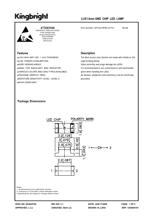
Electrical / Optical Characteristics at TA=25°C
Symbol λpeak λD [1] ∆λ1/2 C VF [2] IR Parameter Peak Wavelength Dominant Wavelength Spectral Line Half-width Capacitance Forward Voltage Reverse Current Blue Blue Blue Blue Blue Blue Device Typ. 468 470 21 100 3.3 3.8 10 Max. Units nm nm nm pF V uA Test Conditions IF=20mA IF=20mA IF=20mA VF=0V;f=1MHz IF=20mA VR = 5V
Tape Specifications (Units : mm)
SPEC NO: DSAG5702 APPROVED: J. Lu
REV NO: V.1 CHECKED: Allen Liu
DATE: JUN/17/2006 DRAWN: W.J.ZHU
PAGE: 4 OF 5 ERP: 1203003781
BLUE
Features
3.2X1.6mm SMT LED, 1.1mm THICKNESS. LOW POWER CONSUMPTION. WIDE VIEWING ANGLE. IDEAL FOR BACKLIGHT AND INDICATOR. VARIOUS COLORS AND LENS TYPES AVAILABLE. PACKAGE: 2000PCS / REEL. MOISTURE SENSITIVITY LEVEL : LEVEL 3. RoHS COMPLIANT.
3216对应的封装
3216对应的封装一、背景介绍二、3216封装的特点三、3216封装的优势四、3216封装的应用领域五、3216封装的制造工艺六、3216封装的市场前景七、总结一、背景介绍随着电子产品的不断发展,电子元器件的封装形式也在不断演变。
3216封装作为一种常见的封装形式,被广泛应用于各个领域。
本文将介绍3216封装的特点、优势、应用领域、制造工艺以及市场前景。
二、3216封装的特点3216封装是一种表面贴装技术(SMT)封装形式,其尺寸为 3.2mm × 1.6mm。
相较于其他封装形式,3216封装具有以下几个特点:1. 尺寸小巧:3216封装的尺寸小巧,能够在有限的空间内实现更高的集成度,满足电子产品对尺寸要求的同时提供更多的功能。
2. 高密度装配:由于3216封装的尺寸小,因此可以实现更高的元器件密度,提高电路板的集成度,减小电子产品的体积。
3. 适应性强:3216封装适用于多种电子元器件,如电容、电阻、电感等,可以满足不同电子产品对元器件的需求。
4. 良好的电性能:3216封装通过优化设计,能够提供良好的电性能,确保电子产品的稳定性和可靠性。
三、3216封装的优势3216封装相较于其他封装形式具有以下几个优势:1. 节省空间:由于3216封装的尺寸小巧,可以在有限的空间内实现更高的集成度,节省电子产品的空间。
2. 提高效率:3216封装通过优化设计,可以提高元器件的装配效率,降低生产成本。
3. 提高可靠性:3216封装具有良好的电性能,能够保证电子产品的稳定性和可靠性,减少故障率。
四、3216封装的应用领域3216封装广泛应用于各个领域,包括但不限于以下几个方面:1. 通信领域:3216封装适用于无线通信设备、基站设备、网络设备等,满足通信领域对小尺寸、高密度集成的要求。
2. 汽车电子:3216封装可以应用于汽车电子领域,如车载导航、智能驾驶、车载娱乐等,提供稳定可靠的电子元器件。
3. 工业控制:3216封装适用于工业控制设备,如PLC、传感器、工业机器人等,提供高密度、高可靠性的电子元器件。
铁氧磁体晶片阵列磁珠为高密度之印刷电路板设计提供小
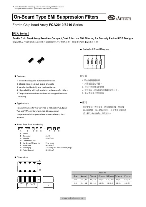
Features
1. Monolithic inorganic material construction. 2. Closed magnetic circuit avoids crosstalk. 3. excellent solderability and heat resistance. 4. High reliability with high insulation resistance of >100M 5.The products contain no lead and also support lead-free soldering. 1. 2. 3. 4. 5. 100M
Four Lines 601=600 T=Taping and Reel, B=Bulk(Bags) 02=200mA
Dimensions
D2
Chip size Size
C
2010 3216
A(mm)
2.0 3.2 0.2 0.2
B(mm)
1.0 1.6 0.2 0.2
C(mm)
0.5 0.9 0.1 0.2
40 68 80 120 25% 25% 25% 25%
Test Frequency (MHz)
100 100 100 100
Rated Current (mA) max.
50 50 50 50
DCR (Ohm) max.
0.15 0.20 0.25 0.30
FCA2010 Series is scheduled to be released in the first quarter of 2003. FCA2010 Series 2003
- 1、下载文档前请自行甄别文档内容的完整性,平台不提供额外的编辑、内容补充、找答案等附加服务。
- 2、"仅部分预览"的文档,不可在线预览部分如存在完整性等问题,可反馈申请退款(可完整预览的文档不适用该条件!)。
- 3、如文档侵犯您的权益,请联系客服反馈,我们会尽快为您处理(人工客服工作时间:9:00-18:30)。
3.2x1.6mm SMD CHIP LED LAMP
APC3216MGC MEGA GREEN
Features
!3.2mmx1.6mm SMT LED, 1.1mm THICKNESS. !LOW POWER CONSUMPTION. !WIDE VIEWING ANGLE. !IDEAL FOR BACKLIGHT AND INDICATOR. ! VARIOUS ! PACKAGE
Note: 1. 1/10 Duty Cycle, 0.1ms Pulse Width.
Meg a Gr een 105 30 150 5 -40°C To +85°C
Un it s mW mA mA V
SPEC NO: DSAD1005 APPROVED : J. Lu
REV NO: V.1 CHECKED :Allen Liu
SPEC NO: DSAD1005 APPROVED : J. Lu
REV NO: V.1 CHECKED :Allen Liu
DATE:MAR/20/2003 DRAWN:D.L.HUANG
PAGE: 1 OF 4
元器件交易网
Selection Guide
Par t No . Dic e L en s Ty p e Iv (m c d ) @ 20 m A Min . APC3216MGC MEGA GREEN ( InGaAlP ) WATER CLEAR 18 Ty p . 70 V i ew i n g An g l e 2θ1/2 120°
Note: 1. θ1/2 is the angle from optical centerline where the luminous intensity is 1/2 the optical centerline value.
Electrical / Optical Characteristics at T)=25°C °
Description
The Mega Green source color devices are made with DH InGaAlP on GaAs substrate Light Emitting Diode.
COLORS AND LENS TYPES AVAILABLE. : 2000PCS / REEL.
Recommended Soldering Pattern (Units : mm)
Tape SpecificatioDSAD1005 APPROVED : J. Lu
REV NO: V.1 CHECKED :Allen Liu
DATE:MAR/20/2003 DRAWN:D.L.HUANG
Absolute Maximum Ratings at T)=25°C °
P ar am e t e r Power dissipation DC Forward Current Peak Forward Current [1] Reverse Voltage Operating/Storage Temperature
PAGE: 4 OF 4
DATE:MAR/20/2003 DRAWN:D.L.HUANG
PAGE: 2 OF 4
元器件交易网
Mega Green
APC3216MGC
SPEC NO: DSAD1005 APPROVED : J. Lu
REV NO: V.1 CHECKED :Allen Liu
DATE:MAR/20/2003 DRAWN:D.L.HUANG
Sy m b o l λpeak λD ∆λ 1/2 C VF IR Par am et er Peak Wavelength Dominate Wavelength Spectral Line Half-width Capacitance Forward Voltage Reverse Current D ev i c e Mega Green Mega Green Mega Green Mega Green Mega Green Mega Green Ty p . 574 568 26 20 2.1 2.5 10 Max . Un it s nm nm nm pF V uA Tes t Co n d it io n s I F =20mA I F =20mA I F =20mA VF=0V;f=1MHz I F =20mA V R = 5V
Package Dimensions
Notes: 1. All dimensions are in millimeters (inches). 2. Tolerance is ±0.2(0.0079") unless otherwise noted. 3. Specifications are subject to change without notice.
PAGE: 3 OF 4
元器件交易网
APC3216MGC SMT Reflow Soldering Instructions
Number of reflow process shall be less than 2 times and cooling process to normal temperature is required between first and second soldering process.