FCR4.0MC5T中文资料
施奈德EOCR保护器新产品中文版

9
EOCR-i Series
Basic model : EOCR-i3DM(Z, S, 420, BZ) / iFDM(Z, S, 420, BZ)
10
EOCR-i Series
Basic model : EOCR-i3DM(Z, S, 420, BZ) / iFDM(Z, S, 420, BZ)
0~30s (i3MS/iFMS)
0.05
(i3MS/iFMS)
0.5s~20min.
,,
100~240VAC/DC(85%~110%, Free voltage), 24VAC/DC( 5%)
50/60Hz
Lower than 7VA
3A/250VAC resistive.
1a1b : OC (i3DM/iFDM, i3MS/iFMS, i3M420/iFM420)
FDZ-05DZ7W(T)A(B), 3DZ-60DZ7W(T)A(B), FMZWRDZ7W(T)A(B)
3D420-059, 3D420-609, 3E420-WR9, 3M420-WR9 3D420-053, 3D420-603, 3D420-056, 3D420-606, 3E420-WR91, 3M320-WR3, 3M420-WR6 FD420-0539, FD420-6039, FD420-0569, FD420-6069, FE420-WR91(3), FM420-WR91(3) FD420-0531(3), FD420-6031(3), FD420-0561(3), FD420-6061(3), FE420-WR3(1), FE420-WR6(1), FM420-WR31(3), FM420-WR61(3) 3DS-05DB, 3DS-20DB, 3MS-05DB, 3MS-20DB
CDRR94NP-100MC中文资料

1.7
0.75
3790-0014
15 CDRR94NP-47ØMC 470 47 μH ± 20% 435.0(348)
1.6
0.70
3790-0015
16 CDRR94NP-68ØMC 680 68 μH ± 20% 670.0(536)
1.3
0.55
3790-0016
17 CDRR94NP-82ØMC 820 82 μH ± 20% 898.0(718)
1-3. DIMENSION RECOMMENDED (mm)
STAMP・DATE CODE
7.1
DIRECTLY STAMP UNFIXED THE POSITION
2.COIL SPECIFICATION 2-1. CONNECTION (BOTTOM )
3.0
3.0
RoHS
compliance
和電流(A) 電流(A) スミダ
※3
※4
コード
(at 20℃) △T=40℃
10.8
5.0
3790-0019
20 CDRR94NP-1R5MB 1R5 1.5μH ± 20% 16.9(13.5)
9.6
4.5
3790-0020
21 CDRR94NP-2R2MB 2R2 2.2μH ± 20% 27.5(22.0)
DECREASES TO 10% LOWER OF IT'S INITIAL VALUE. ※4 TEMPERATURE RISE: THE VALUE OF D.C.CURRENT WHEN THE TEMPERATURE RISE IS △t=40℃(Ta=20℃).
元器件交易网
3.0
迈克罗斯 47007-0005450 远程控制器用户指南说明书

For countries outside the European Union:
If you wish to discard these items, please contact your local authorities or dealer and ask for the correct method of disposal.
• If you must operate this unit while driving, do not take your eyes off the road or an accident could result.
• If any of the following problems occur, immediately stop using this unit and consult your dealer from whom you purchased this unit: – smoke coming from the unit. – abnormal odors or smells. – a foreign object has entered the unit. – liquid has been spilled on or into the unit. If you continue to use the unit when it is not operating properly, damage could result in an accident or fire.
Notes
• Depending on the car stereo, there may not be some buttons with the same names as those on this unit.
钢铁大侠Dixon A540系列地面接线器说明书

A540 SERIES GROUND CLAMPContentsOverview (2)Features (2)Technical Specifications (3)Installation (6)Maintenance (8)Replacement parts (8)Operation (9)Warranty (9)Sales and Service Contacts (10)OverviewThe A540 Series ground clamps are key to creating a quality temporary connection for antistatic grounding applications. The clamp features three teeth to penetrate dirt, corrosion, and road grime when in use. The teeth are constructed of stainless steel to ensure lasting operation, and isolated from the clamp handle to allow operators to establish ground and a ground-verification signal in a single clamp action. The A540 also includes a high durability cable and junction box for convenient wiring access during installation and maintenance.Common applications for the A540 series ground clamp include:•Tank truck and Rail car loading facilities•Drum and barrel filling sites•Loading of stationary tanksFeatures•Clamp tethered to cable by stainless steel strap to protects connection from strain and wear. •Pull-out resistant cord grip on junction box holds cable tighter the harder it is pulled. •Junction box creates convenient service point for hazardous location installations.•Coiled cable for compact storage.•Strong clamping force to penetrate grime and remain connected during loading process. •Can provide ground and a ground-verification signal in a single clampTechnical SpecificationsMIN MAX NOMINAL AMBIENT TEMPERATURE -40°C 90°C -JUNCTION BOXHEIGHT 10.75 in. [27.3cm] INCLUDES STRAIN RELIEFWIDTH 3.0 in. [7.62cm]DEPTH 3.0 in. [7.62cm]WEIGHT 5 lbs. (2.27 kg)INGRESS PROTECTION Weatherproof, raintight, and dust tightCONDUIT ENTRIES ONE ¾” TRADE SIZE HOLE + FACTORY INSTALLED CABLE ONBOTTOMSUITABLE FOR INSTALL IN HAZARDOUS LOCATIONS: Class I, Division 1 & 2, Groups B, C, and D hazardous locationsClass II, Division 1 & 2, Groups E, F, and G hazardous locationsClass III hazardous locationsSUITABLE FOR CONNECTION TO HAZARDOUS LOCATIONS: Class I, Division 1 & 2, Groups A, B, C, and D hazardous locationsClass I, Zone 0, 1 & 2, Groups IIC, IIB, and IIA hazardous locationsCABLELENGTH 25 ft. stretched [7.6m] (Standard; other lengths available) DIAMETER 0.4 in. [1.0cm]WEIGHT 2.5 lbs. [1.13kg]; 0.1 lbs. PER FOOT [0.15g per meter] JACKET MATERIAL Thermoplastic Elastomer, resistant to harsh environments. RESISTANCE 0.14Ω (6mΩ/foot)RECOMMENDED WIREBETWEEN CONTROLLER ANDA54018 GA Stranded copper wire (THHN)AccessoriesGround Verification Monitor:The A240 series ground verification monitors are designed to mitigate the danger of static buildup by verifying the presence of a high quality and reliable earth-ground bond. With the presence of a ground path for static to dissipate, loading and unloading of flammable or combustible liquids can be done safely. The A240 monitor verifies the bond is of sufficient quality to prevent static buildup. Internal indicators inform the operator whether the process connection is safely grounded and internal relay contacts may be used to interlock operations until a safe earth bonding has been established.Sealing Fitting:Sealing fittings are required within 18 inches of each enclosure entry used. These seal conduits from passing hazardous vapors or propagating flame. Sealing fittings are installed in-line with conduit, then filled with sealing compound once wiring has been installed and verified. Downstream junction boxes containing Intrinsically Safe circuits may be serviced without danger.¾” NPT Vertical Seal fitting with nipple; P/N: 30192ALNote: Actual color may differWiring DiagramInstallationINSTALLATION MUST BE COMPLETED BY QUALIFIED PROFESSIONALA540 Series ground clamps are suitable for installation and use in ordinary and specific hazardous locations (listed in technical specifications section) as defined by NEC NFPA70 and IECEx standard 60079. Installation to be performed by a qualified professional.MechanicalIt is recommended to wall mount the unit using stainless steel or galvanized steel hardware suitable for the monitor’s weight and wall material.ing the bolt pattern provided below, locate a sturdy area, large enough to install the junctionbox.For greatest environmental resistance it is recommended to mount the junction box in theorientation shown. Keep in mind the coiled cable will hang below the box, and the clamp must be stored in an ungrounded position. The enclosure can withstand rain and sun exposure butwill last longer when protected from the elements.2.Level the bolt pattern and drill two holes marked on the pattern.3.Have another person lift the junction box into position in front of the drilled holes.4.Insert the two anchors or bolts into the two mounting holes shown below.5.Tighten all the screws and ensure that the junction box is secure.Electrical•To be installed per NEC NFPA70 requirements for U.S. installations.•Installation in other regions must conform to local electrical codes. Instructions provided below are general guidelines and may not cover local requirements.1.Remove the lid from the A540 junction box.2.Run conduit to junction box. Ensure conduit has sealing fitting at feeder end if installation is inhazardous location.Conduit connection should be sealed from water intrusion through either rubber washers,caulking, or other sealing means.3.Pull cable from process controller into A540 junction box.4.Refer to wiring diagram above, as well as documentation for process controller to properly wirethe process controller to the A540 ground cable.5.Reinstall lid onto junction box.6.Designate an ungrounded location to store the ground clamp while not in use. It is critical thatthe ground clamp be ungrounded while not in use. Storing in a grounded state can lead tounsafe loading conditions.7.Verify proper functionality of system by testing before putting into service.MaintenanceSERVICE SHOULD BE COMPLETED ONLY BY A QUALIFIED HAZARDOUS LOCATION TECHNICIAN. REPLACE PARTS WITH GENUINE DIXON OR APPROVED EQUIVALENT PARTS; SUBSTITUTION MAY IMPAIR INTRINSIC SAFETY.The A540 has few parts that will require regular maintenance and is designed for long service periods. Unsheltered units should be serviced in dry weather to prevent rainwater from entering the enclosure and minimize moisture exposure.1.If the ground connection is becoming intermittent, it is advised to inspect the clamp and cable.2.Dulling of the clamp teeth may be a sign that the clamp has reached the end of its usable lifeand should be replaced. Contact Dixon for replacement parts.3.Checking the cable for a failing conductor can be done by clamping to a known grounded pieceof metal, then flexing the cable. If the ground controller’s indicator changes while flexing thecable, the cable has reached the end of its usable life and should be replaced. Do not attempt to repair the cable. Contact Dixon for replacement parts.a.In the event that the cable does need to be replaced, it can be removed while energized.b.Open the A540 junction box and note the wire positions for each conductor in the A540cable on the terminal block.c.Remove the wires from the terminal block.press the mesh cordgrip by pushing it toward the bottom of the junction box.e.With the cordgrip compressed, the old cable may be pulled out, and new cable installed.f.Once the new cable has been installed into the mesh cordgrip, re-wire the cable into theA540 junction box terminal strip.g.Close the A540 junction box.h.Verify proper functionality of system by testing before putting into service. Replacement partsDescription Part NumberRack Cable with clamp 30585Cord Grip 30708Sealing Fitting; ¾” Vertical 30129ALSealing Compound 30339 for 5 lbs. or 30339-002 for 1 lb.OperationWARNING - USING THE A540 IN A MANNER NOT DEFINED IN THIS MANUAL MAY IMPAIR SAFETY.1.Verify process controller is powered on and idle.2.Test the controller’s operation by clamping to a known grounded piece of metal. Verify thecontroller’s indicator changes from RED to GREEN. Remove the clamp from the test point.3.Before any other electrical connections are made, secure the A540 clamp to the processconnection that is to be loaded.4.Verify the process controller’s indicator changes from RED to GREEN.plete any other process connections.6.Once all other safety measures are active, begin the loading process.7.Once loading is complete, remove all other process connections, then the A540 last.8.Return the A540 clamp to the isolated storage facility, verifying the indicator remains red. WarrantyFor warranty claims and information regarding coverage, please contact Dixon Support at+1 (877) 582-3569Sales and Service ContactsEurope:Dixon Group Europe Ltd.Preston, EnglandPhone: +44 (0) 1772 323529Fax: +44 (0) 1772 314664Email: ************************.ukCanada:Dixon Group Canada Limited Innisfil (Barrie), OntarioPhone: 705-436-1125Fax: 705-436-6251Toll Free: 877-963-4966E-mail: ***************************USA:Dixon Bayco USAChestertown, MarylandPhone: 410-778-2000Fax: 410-778-4702Toll Free: 800-355-1991E-mail: *************************Mexico:Dixva, S. de R.L. de C.V.Monterrey, N.LPhone: 01-800-00-DIXON (34966)Fax: 01-81-8354-8197E-mail: **************************.mxAsia Pacific:Dixon (Asia Pacific) Pty Ltd Wingfield, South AustraliaPhone: +61 8 8202 6000Fax: +61 8 8202 6099E-mail: ************************.au。
MCR极限值开关说明

在概述中的用于单独设置的章节中的阴影线中,你可以看到 在每个菜单中如何返回到特别的开始点。在这下面,你可以 看到如何选择希望的设置。
显示测试
测试选项
MCR极限值开关,可编程-MCR-PSP
设置输入 首先决定输入信号。如果它是一个RTD 或TC传感器,也要选择温度显示单位-摄氏度°C和华氏度°F- ,并且如果是RTD传感器 时,你必须也选择传感器的类型和传感器的阻抗(在0°C时)。
选择温度的单位 操作的体系
选择传感器和电阻 (只用于RTD)的类型
键组合▲.▲从测量值显示切换到编辑模式,在这里随后输 入设置被显示。
注意: 这三个键必须被直接一个接一个按下。如果在两个键 按下之间有一个大于2秒的停顿,模块返回到测量值显示。其 时间限制由从左到右的发亮被显示:如果在第5个数字时熄灭 了,模块返回到测量值显示。
图1
图2 这个模块既可以用MCR-PI-CONF-WIN软件(见第15页 ),也可以用带膜键区被编程。这个装置可以适用于 各种在前面使用键盘和显示的应用。LED显示连续显 示当前测量值,因此过程值夜可以被可视监视。 两个继电器被设计为具有可调整地时间继电器的PDT 接点,并且每个接点的限值有一个可修改的磁滞。 这个选项给了你能够设置四个互相独立的开关限值 的优势。为了提供另外的诊断,继电器可以被连接 为在到模块的辅助电压一个故障模式期间吸合或释 放。假如断线或短路,每个继电器可以通过软件或 键盘被设置为吸合或释放。在缺省设置中两个继电 器都被设置为吸合。 具有隔离输入的装置解耦现场电平和辅助电源,因 此避免测量电路干扰的产生。 壳子时45mm宽,并且连接有可插入式螺钉端子连接 (COMBICON), 并且可以被安装在能买到的EN安 装轨道上。
西驰电气CFC5000通用变频器使用说明书

-2-
CFC5000 系列变频器手册
1.2 其它
第一章 安全注意事项
》 本变频器不适用于超出本手册规定的规格范围,客户如有特殊需求,请致电我公司技 术部。 》 本系列变频器内部配有浪涌抑制器,对雷电有一定的保护能力,但雷电高发地区,请 用户在变频器电源输入端加装外部浪涌抑制器。 》 当变频器和电机之间的导线超过 100 米时,建议加装输出电抗器,以避免过大的分布 电容而产生的过流保护故障。 》 请勿在变频器的输出端安装补偿电容器和浪涌吸收器,否则有可能因过热损坏变频器 的危险。
第三章 使用指南 …………………………………………………………12 3.1 安装环境……………………………………………………………………12 3.2 变频器安装及间隔距离……………………………………………………12 3.3 操作键盘及盖板的安装和拆卸……………………………………………13 3.4 产品外围预案器件及说明…………………………………………………16 3.5 主电路接线端子图…………………………………………………………18 3.6 标准接线图…………………………………………………………………19 3.7 主回路连接…………………………………………………………………20 3.8 控制回路连接………………………………………………………………22 3.9 配线中的 EMC 问题…………………………………………………………27
1.1 安全事项 1.1.1 安装前:
》 开箱时发现机器进水或遗留有水迹,表示变频器曾经进水,请不要安装使用。 》 开箱时发现机器破损变形或部件缺失,请不要安装使用,否则有故障扩大和人员受伤 的危险。 》 不要用手直接触摸变频器内部的控制端子、PCB 板及变频器部件。
MC5参数表
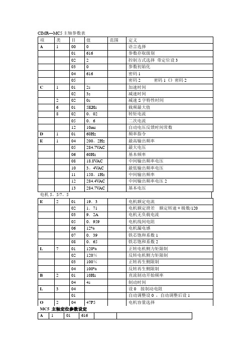
2
01
19.3
电机额定电流
02
1.71
电机额定滑差额定转速*极数/120
03
9.2A
电机无负载电流
05
0.959
电机线间电阻
06
12%
电机漏电感
07
0.39
铁芯饱和系数1
08
0.65
铁芯饱和系数2
L
7
01
120%
正转电机侧力矩限制
02
120%
反转电机侧力矩限制
03
100%
正转再生侧限制
04
100%
反转再生侧限制
B
2
01
10Hz
直流制动开始频率
04
4s
制动时间
L
3
04
设0接制动电阻
01
自动调整设0,自动调整后设1
O
2
04
47P5
电机容量选择
MC5主轴定位参数设定
A
1
01
616
02
3
03
0
04
616
E
1
09
0B1ຫໍສະໝຸດ 071H1
01
2
3
01
0
设电压0:+10V,1:±10V
P
3
01
0
0~4095
设置分度位置
自动电压反馈时间常数
D
1
01
60Hz
频率指令
E
1
04
200。2Hz
最高输出频率
05
284.7VAC
最大电压
06
60Hz
基本频率
08
MCT系列温度变送器使用说明书

MCT系列温度变送器使用说明一、产品概述MCT系列温度变送器是一种廉价精巧的24VCD供电、二线或三线制输出的变送器,主要分为模块式,导轨式,壁挂式安装三种。
产品采用集成电路,将热电阻或热电偶的信号放大并转换成4-20mA(国际标准二线制)电流信号或0-5V、0-10V(非标三线制)电压信号输出。
模块式电流输出型变送器有如下特点:可方便直接安装在传感器接线盒内,可远传(最大1000m)、精度高、抗干扰、稳定性好,导轨式可密集安装,壁挂式可挂于室内墙壁。
该系列产品已广泛应用于工业控制各领域。
二、工作原理温度传感器受温度影响产生电阻或电势效应,经转换产生一个电压信号。
此信号经仪用运放放大后送出与量程相对应的4-20mA电流信号或0-5V、0-10V电压信号。
三、主要技术性能1、热电阻测量范围:Pt100:-100~600℃;Cu50:-50~50℃,可输出4-20mA,0-5V,0-10V2、热电偶测量范围:0-1300℃,可输出4-20mA等信号3、测量精度:热电阻:±0.2%,±0.3% 热电偶:1% 冷端补偿精度±2℃/60℃4、温度漂移:精品级温漂<±0.01%/℃,年漂移<±0.5%;普通工业级温漂<±0.025%℃5、工作温度:-20~70℃6、供电电压:24VDC±10%(4-20mA电流型变送器最低工作电压需要10V,余下可供负载使用),电压输出型的供电电压高出输出电压4V即可工作(如0-5V,9V供电即可),一般分为12V及24V两种供电,定购时须申明7、负载能力:(4-20mA电流型)0~500欧姆,电压变化影响<±0.015%/V,电压型最大输出电流<3mA8、环境湿度:<85%且无腐蚀性9、变送器内设有TVS(30V/1.5A),26mA过流保护四、型号命名与含义型号类型分度号级别(P-工业;Z-精品)MCT80AR 模块(热电阻)Pt100,Cu50 P,ZMCT80AC 模块(热电偶)K PMCT80D-R 导轨式安装(热电阻)Pt100(25mm-35mmDIN导轨非隔离型) P,ZMCT80D-C 导轨式安装(热电偶)K(25mm-35mmDIN导轨非隔离型)PMCT80B 壁挂型一体化(Pt100)测温范围-50—70℃PMCT80Y/X 数显一体化4-20mA型变送器P五、使用与校准1、安装与接线变送器系统联接图1所示,24VDC通过屏蔽电缆给变送器供电,24V的正极接变送器的“+”极,“—”输出4-20mA,接各种数显表输入的“+”端或计算机的取样电阻,数显表输入的“—”端与24V负极共地。
504FT质量流量计说明书_KURZ-ok要点

504FT系列热式质量流量计中文使用说明书第一部分概述1、仪表检查:504FT仪表收到后,在安装到管道前,先做检查,以确保仪器在安装前是正常的,具体检查步骤如下:图1 电气接线图(1)仪表是24VDC供电,把电源24VDC 接到TB1接线端的1# 和2#,其中1# 接+24V;(2)如果是非隔离输出(见附件2):首先检查:接线端的3# 和5# 及3# 和7# 短接,如已接好,则不用再短接;其次:检查接线正确后,仪表通电,然后用万用表的电流挡测量2# 和6# 及2# 和8# 的4~~20mA 电流,其中,2# 和6# 是流量/流速输出,2# 和8# 是温度输出;并且用手感觉一下传感器是否发热(传感器应该是发热的);第三:无风的状态下,2# 和6# 输出应为4mA,(因为那时流量为零);2# 和8# 应有一个大于4mA的输出;(因为这时是有温度的,所以应该有电流输出)(3)如果是隔离输出(见附件2,此装置是按照隔离输出来连接的)。
(4)一个模拟风量来检查仪器是否对风速有响应;可以通过显示面板查看或则量注意:如果该表已经做了小流量切除的话,当小于这个流量时,面板流量指示为零,并且4~~20mA的输出也是4mA;只有当流量大于所切除的小流量时,才有流量显示和4~~20mA 电流输出;(5)进行上述这些检查后,仪表对流量有响应,说明仪表正常,然后再安装到管道上。
并且要正确接线,安装时要注意气体流向,表上的箭头同气体流向一致;同时要注意4~~20mA输出信号线的接线方法,具体见附件1和2。
第二部分介绍1、工作原理504FT系列流量变送器采用热传导原理测量气体的质量流量. 传感元件包括两个带热套管保护的电阻式温度传感器(RTD),测量流体时一个电阻式温度传感器(加热RTD)被加热, 另一个电阻式温度传感器(参比RTD)用于测量流体温度. 利用惠斯通电桥反馈电路控制加热传感器的功率来保持加热传感器和参比温度传感器之间的温差恒定. 气体流动时加热传感器和参比温度传感器之间存在的热量差值和气体的质量流量成函数关系即可测量气体的质量流量.2.安装1)已经安装完毕,请检查连接处是否有泄漏,如果有,可以重新紧固连接处;否则,请不要轻易扳动任何连接管件。
弗朗克说明书讲解

用户手册FRS2000系列软起动器(15…500KW)佛朗克集团(德国)有限公司目录1.产品型号及收货检查 (2)2.安装 (2)3.原理框图 (4)4.技术参数 (6)5.接线 (6)5.1端子功能说明 (6)5.2推荐接线图 (7)5.3附件选用 (8)6.设定 (9)6.1软启动器通过键盘键盘进行设定 (9)6.1.1初始电压设置 (10)6.1.2起动时间设置 (10)6.1.3停止时间设置 (10)6.1.4起动电流设置 (10)6.2R S485通讯控制 (11)7.软起动器功能表 (15)8.功能详细解释 (16)9.状态指示 (20)10.维护 (21)11.故障分析……………………………………………………………………………22 1. 产品型号及收货检查为了充分地发挥本软起动器的功能,及确保使用者的安全,请详细阅读本操作手册。
当您使用中发现某些疑难问题而本操作手册无法给您解答时,请联络本公司各地代理商、经销商或本部工程技术人员,我们的专业人员将乐于为您服务。
软起动器是电力电子新产品,为了您的安全,本手册中有“危险”、“注意”等符号提醒您在搬运、安装、运转、检查软起动器时的安全防范事项,请您配合使软起动器的使用更加安全。
1.1铭牌检查请检查您收到的货物与您所订购的产品型号是否相符。
1.2产品检查请检查产品在运输过程中是否有损伤,如:外壳凹陷、变形,连线、连接件松动等。
1.3 开箱检查每台软起动器配产品合格证、用户手册各一份。
请检查资料是否齐全。
2.安装为保证良好的产品性能,软起动器必须垂直安装。
安装空隙应遵循下表。
安装环境通风良好,室内安装,避免阳光直射。
环境温度:-10℃~+50℃相对湿度:≤95%(20℃±5℃)环境条件:无易燃、易爆、腐蚀性气体,无导电尘埃室内安装,通风良好振动小于0.5G海拔超过1000 米,应相应降低容量使用结构尺寸图:外形尺寸(单位:mm)规格型号A(高) B(宽)C(厚)E(高)F(宽)ф(孔径)FRS2015(15KW)250 153 162 219 140 Φ6FRS2022(22KW)360 200 200 260 150 Φ11FRS2030(30KW)360 200 200 260 150 Φ11FRS2037(37KW)360 200 200 260 150 Φ11FRS2045(45KW)360 200 200 260 150 Φ11FRS2055(55KW)360 200 200 260 150 Φ11FRS2075(75KW)360 200 200 260 150 Φ11FRS2090(90KW)400 275 260 280 245 Φ11FRS2110(110KW)400 275 260 280 245 Φ11FRS2132(132KW)400 275 260 280 245 Φ11FRS2160(160KW)400 275 260 280 245 Φ11FRS2200(200KW)400 275 260 280 245 Φ11FRS2220(220KW)450 275 300 285 245 Φ11FRS2250(250KW)450 275 300 330 245 Φ11FRS2280(280KW)450 275 300 330 245 Φ11FRS2315(315KW)450 275 300 330 245 Φ11FRS2355(355KW)450 275 300 330 245 Φ11FRS2400(400KW)520 500 280 435 300 Φ11FRS2500(500KW)520 500 280 435 300 Φ113.原理框图采用三组反并联SCR 模块作为功率器件,CPU1 为控制单片机,CPU2 为指令输入和显示单片机,通过对输入电压取样电路获得同步信号,对输出电流取样进行反馈模糊控制,自动跟踪相位、控制移相角,使电压逐步上升,根据负载情况,改变转矩,从而控制起动电流。
FCR10.0MC5中文资料
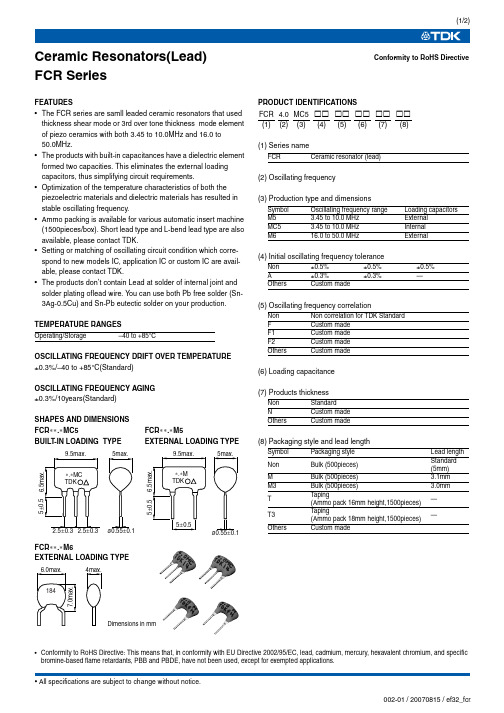
Ceramic Resonators(Lead) FCR SeriesFEATURES•The FCR series are samll leaded ceramic resonators that used thickness shear mode or 3rd over tone thickness mode element of piezo ceramics with both 3.45 to 10.0MHz and 16.0 to50.0MHz.•The products with built-in capacitances have a dielectric element formed two capacities. This eliminates the external loading capacitors, thus simplifying circuit requirements.•Optimization of the temperature characteristics of both the piezoelectric materials and dielectric materials has resulted in stable oscillating frequency.•Ammo packing is available for various automatic insert machine (1500pieces/box). Short lead type and L-bend lead type are also available, please contact TDK.•Setting or matching of oscillating circuit condition which corre-spond to new models IC, application IC or custom IC are avail-able, please contact TDK.•The products don’t contain Lead at solder of internal joint and solder plating oflead wire. Y ou can use both Pb free solder (Sn-3Ag-0.5Cu) and Sn-Pb eutectic solder on your production.TEMPERATURE RANGESOSCILLATING FREQUENCY DRIFT OVER TEMPERATURE±0.3%/–40 to +85°C(Standard)OSCILLATING FREQUENCY AGING±0.3%/10years(Standard)SHAPES AND DIMENSIONSFCR∗∗.∗MC5FCR∗∗.∗M5BUILT-IN LOADING TYPE EXTERNAL LOADING TYPEPRODUCT IDENTIFICATIONS(1) Series name(2) Oscillating frequency(3) Production type and dimensions(4) Initial oscillating frequency tolerance(5) Oscillating frequency correlation(6) Loading capacitance(7) Products thickness(8) Packaging style and lead lengthConformity to RoHS DirectiveOperating/Storage–40 to +85°C FCR 4.0MC5(1)(2)(3)(4)(5)(6)(7) (8)FCR Ceramic resonator (lead)Symbol Oscillating frequency range Loading capacitors M5 3.45 to 10.0 MHz ExternalMC5 3.45 to 10.0 MHz InternalM616.0 to 50.0 MHz ExternalNon±0.5%±0.5%±0.5%A±0.3%±0.3%—Others Custom madeNon Non correlation for TDK StandardF Custom madeF1Custom madeF2Custom madeOthers Custom madeNon StandardN Custom madeOthers Custom madeSymbol Packaging style Lead length Non Bulk (500pieces)Standard(5mm) M Bulk (500pieces) 3.1mmM3Bulk (500pieces) 3.0mmTT aping(Ammo pack 16mm height,1500pieces)—T3T aping(Ammo pack 18mm height,1500pieces)—Others Custom made•Conformity to RoHS Directive: This means that, in conformity with EU Directive 2002/95/EC, lead, cadmium, mercury, hexavalent chromium, and specific bromine-based flame retardants, PBB and PBDE, have not been used, except for exempted applications.ELECTRICAL CHARACTERISTICS∗ ±0.5% is standard.• These values are typical. Application frequency are also available. Please contact TDK.RELIABILITY AND TEST CONDITIONSThe following test items are satisfied.(1) Oscillating frequency change: within ±0.25%(2) Resonant resistance change: within ±10Ω(3) Appearance, serious abnormalities not to exist.SOLDERABILITYThe lead wires are adopted Pb free plating wire to apply Pb free soldering. Y ou can also use current Sn-Pb eutectic solder.RECOMMENDED SOLDERING CONDITIONSThis is the fit product for flow soldering.FLOW SOLDERING CONDITIONPart No.Oscillating frequency Fosc(MHz)Resonant impedanceRo(Ω)Initial Fosc tolerance∗(%)Capacitance CL1/CL2(pF)FCR∗∗.∗MC5 type(Built-in loading type)FCR3.45MC5 3.4520±0.530/30 FCR3.52MC5 3.5220±0.530/30 FCR3.58MC5 3.5820±0.5/0.330/30FCR3.84MC5 3.8420±0.530/30 FCR4.0MC5 4.0020±0.5/0.330/30 FCR4.19MC5 4.1920±0.5/0.330/30 FCR5.0MC5 5.0020±0.5/0.330/30 FCR6.0MC5 6.0020±0.5/0.330/30 FCR8.0MC58.0030±0.5/0.320/20FCR10.0MC510.0030±0.5/0.320/20 FCR∗∗.∗M5 type(External loading type)FCR3.45M5 3.4520±0.5FCR3.52M5 3.5220±0.5FCR3.58M5 3.5820±0.5/0.3FCR3.64M5 3.6420±0.5FCR4.0M5 4.0020±0.5/0.3FCR4.19M5 4.1920±0.5/0.3FCR5.0M5 5.0020±0.5/0.3FCR6.0M5 6.0020±0.5/0.3FCR8.0M58.0030±0.5/0.3FCR10.0M510.0030±0.5/0.3FCR∗∗.∗M6 type(External loading type)FCR16.0M616.0040±0.5FCR18.0M618.0040±0.5FCR18.43M618.4340±0.5FCR24.0M624.0040±0.5FCR33.86M633.8640±0.5FCR40.0M640.0040±0.5T est items T est conditionsLow temperature storage characteristics T emperature: –40±3°C Time: 1000hHigh temperature storage characteristics T emperature: +85±2°C Time: 1000hHumidity resistance Humidity: 90 to 95(%)RH T emperature: 60±2°C Time: 100hThermal shock–40°C (30min), 85°C (30min) x 100 cycles Soldering heat resistance Solder temperature: peak 260°C, 10s flowDrop Drop 3 times onto the concrete from a height of 1mVibration Frequency: 10⇔ 55⇔ 10Hz/minAmplitude: 1.5mmX, Y and Z directions for 2h eachT est conditions T est resultWith Rosin-ethanol 25% by weight,dip in Sn-Pbeutectic solder bath at 230±5°C for 3±0.5sec. orPb free solder(Sn-3Ag-0.5Cu) bath at 245±2°Cfor 3±0.2sec.95% minimum ofsurface should becovered by new solder.Heat-resistant temperature260±5°CHeat-resistant time10±1sec.Number of times1time。
四路视频光端机技术参数
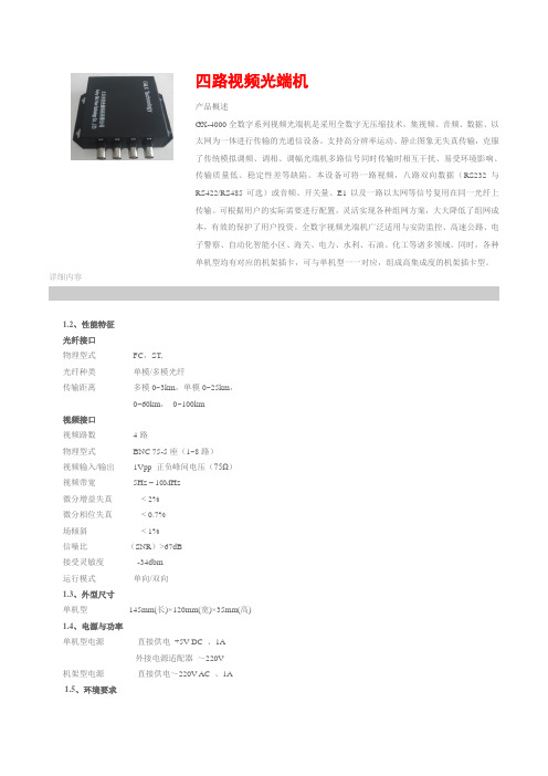
四路视频光端机产品概述GX-4000 全数字系列视频光端机是采用全数字无压缩技术,集视频、音频、数据、以太网为一体进行传输的光通信设备。
支持高分辨率运动、静止图象无失真传输,克服了传统模拟调频、调相、调幅光端机多路信号同时传输时相互干扰、易受环境影响、传输质量低、稳定性差等缺陷。
本设备可将一路视频,八路双向数据(RS232与RS422/RS485可选)或音频、开关量、E1以及一路以太网等信号复用在同一光纤上传输。
可根据用户的实际需要进行配置,灵活实现各种组网方案,大大降低了组网成本,有效的保护了用户投资。
全数字视频光端机广泛适用与安防监控、高速公路、电子警察、自动化智能小区、海关、电力、水利、石油、化工等诸多领域。
同时,各种单机型均有对应的机架插卡,可与单机型一一对应,组成高集成度的机架插卡型。
详细内容1.2、性能特征光纤接口物理型式FC,ST,光纤种类单模/多模光纤传输距离多模0~3km,单模0~25km,0~60km,0~100km视频接口视频路数 4路物理型式BNC 75-5座(1~8路)视频输入/输出1Vpp 正负峰间电压(75Ω)视频带宽5Hz – 10MHz微分增益失真< 2%微分相位失真< 0.7%场倾斜< 1%信噪比(SNR)>67dB接受灵敏度-34dbm运行模式单向/双向1.3、外型尺寸单机型145mm(长)×120mm(宽)×35mm(高)1.4、电源与功率单机型电源直接供电+5V DC 、1A外接电源适配器~220V机架型电源直接供电~220V AC 、1A1.5、环境要求工作温度-40℃ ~ +85℃相对湿度5% ~ 95%GX-4000系列数字光端机产品:四路视频四路视频+一路反向数据四路视频+一路反向数据+一路双向音频(1-8可选)四路视频+一路反向数据+1-8路单向或双向(数据音频开关量可选)四路视频+一路反向数据+1-8路单向或双向(数据音频开关量可选)+一路100M以太网四路视频+一路反向数据+1-4路单向或双向(数据音频开关量可选)+一路100M以太网+1-4路电话(可选)。
往复式压缩机说明书4M125
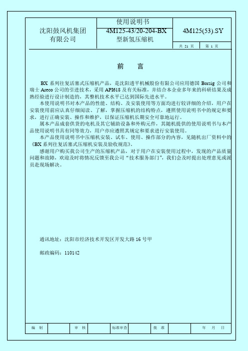
使用说明书沈阳鼓风机集团4M125-43/20-204-BX4M125(53).SY 有限公司型新氢压缩机共21 页第1 页前言BX系列往复活塞式压缩机产品,是沈阳透平机械股份有限公司应用德国Borsig公司和瑞士Areco公司的引进技术,采用API618及有关标准,并结合本企业多年来的科研结果及成熟经验进行设计制造的,其整机技术水平已达到国际先进水平。
本使用说明书对本产品的性能、结构、及安装使用等方面均进行较详细的介绍,用户在安装使用前应认真仔细阅读、了解,掌握压缩机的结构特点,遵照使用说明书中的规定和要求,进行正确安装、操作和维护,以保证压缩机长期安全可靠地运行。
属本产品成套供货的电机及其它辅助设备和外购元件,其随机提供的使用说明书与本产品使用说明书具有同等效力,用户亦应遵照其规定和要求进行安装使用。
本产品使用说明书中压缩机安装、试车、使用、操作部分的内容,见随机出厂资料中的《BX系列往复活塞式压缩机安装及验收规范》。
感谢用户购买我公司生产的压缩机产品,对于用户在安装使用过程中,发现的产品质量问题和故障,欢迎及时将情况反馈至我公司“技术服务部门”,我们会及时提出处理意见或派员赴现场解决。
通讯地址:沈阳市经济技术开发区开发大路16号甲邮政编码:1101421、用途及总体结构概述4M125-43/20-204-BX型新氢压缩机,是为中国石油化工股份有限公司石家庄炼化分公司150万吨/年渣油加氢处理装置设计制造的,亦适用使用相同介质并符合其压力和气量下的其它工业部门。
本产品为对称平衡型、气缸水冷、压力循环润滑、电机拖动,各列气缸水平布置并分布在曲轴两侧,具有动平衡性好,操作检修方便等优点。
本产品对于气、水、油的压力、温度,设有指示仪表和自动监控仪表装置,能在危险工况下发出报警讯号和停机联锁保护,并设置气体超压安全泄放装置。
本产品是在消化吸收引进技术基础上进一步提高技术水平的新产品,具有设计先进、结构合理、性能可靠、噪声低、振动小、易损件使用周期长等特点。
天津院四代篦5500T冷机液压系统说明书
篦冷机液压系统使用说明书北京中冶迈克液压有限责任公司2009年02月22日用户手册前言本手册是用来让用户熟悉蓖冷机液压系统并正确的使用该系统。
如从事以下作业的人员:现场电气操作人员,液压站维护人员及现场调试人员需仔细阅读。
对于使用本设备的人员,在其运行相关作业前,该液压系统的用户必须告知其本手册的内容,特别是安全说明。
包括有关本元件/液压系统安全、正确和经济运行的重要信息。
仔细阅读这些内容将有助于避免危险的发生。
降低维修成本并缩短检修所造成的停工期。
提高元件液压系统的可靠性并延长其使用寿命。
一.设备介绍1.主要技术参数工作介质抗磨液压油VG46/40℃介质清洁度NSA 8级系统额定压力 21MPA变量泵 4台(3用一备连续工作制)最大流量 140L/min电机功率 75KW/380VAC2.概述(1)工作原理其工作原理是(以第一组为例)液压泵(12)将液压油从邮箱抽出,通过泵出口P端将高压过滤器(18)打入组合比例换向阀(38.1),比例换向阀通过不断换向将油有A或B出口,打入液压缸的有肝腔或无肝腔,推动液压缸的活塞做往复运动,液压缸通过传动轴将动力传递给活动框架,从而实现活动篦床的往复运动。
(2)温度控制<30℃加热、>40℃停加热器、>47℃冷却、<35℃停冷却、<20℃低温报警、>50℃高温报警、>60℃停高温跳停。
(检修完后开机时要注意温度,如温度太低要先加热到20℃在开机)(3)压力系统最高压力为210公斤,正常工作中会低于此压力很多,如突然负载过大,工作压力达到最高210公斤,为保护设备液压站会延时一段时间后跳停。
3.主要组成元件及功能动力元件:液压泵(12)(其中3台主泵、1台备用)功能:产生油流和油压。
执行元件:液压缸(共24台)功能:推动篦床往复运动。
控制元件:比例阀(3套分为12组Yp1-Yp12)功能:控制液压缸运动的方向和速度。
循环系统:循环泵(24)吸油经冷却器(29)冷却后,再有过滤器(3)过滤后回油箱。
可控硅MCR参数
可控硅MCR参数可控硅(Silicon Controlled Rectifier,SCR)是一种半导体器件,可通电流方向正向,关断电流方向反向。
它由四个或更多层P-N结组成,具有单向导电性,当控制电压施加在门极上时,可控硅进入导通状态,反之,则进入阻断状态,由此实现电流的控制。
可控硅广泛应用于电力电子领域,如交流电压调速、电磁起动、直流电流调节等。
可控硅的主要参数有:1.封装形式:可控硅可以采用不同的封装形式,如TO-92、TO-126、TO-220等,不同的形式适用于不同的应用场合。
封装形式会影响到可控硅的散热性能和安装方式等。
2. 额定电压(Vdrm):可控硅能够承受的最大正向电压。
超过此电压将会损坏可控硅。
额定电压是选择可控硅时需要考虑的重要参数。
3.额定电流(It):可控硅能够承受的最大正向电流。
超过此电流将会损坏可控硅。
额定电流是选择可控硅时需要考虑的重要参数。
4. 关断速度(didt):可控硅关断的最大速度。
当电流减小得太快时,可控硅可能无法完全关断,导致通电状态。
关断速度越高,可控硅的适用范围就越广。
5. 门极电流(Igt):控制可控硅导通的最小门极电流。
当门极电流超过此值时,可控硅进入导通状态。
门极电流越小,可控硅的控制灵敏度就越高。
6. 阻断电流(Irrm):可控硅在阻断状态下可能存在的泄漏电流。
阻断电流越小,可控硅的关断性能就越好。
7.温度特性:可控硅的性能与温度有关,一般会在数据手册中给出温度特性曲线。
温度特性是选择可控硅时需要考虑的重要参数。
可控硅的参数对于设备的性能和可靠性有重要影响,因此在选择可控硅时应综合考虑不同的参数,并根据具体应用需求进行选择。
同时,在使用可控硅时,也应根据数据手册中的参数,合理设计电路,确保可控硅的正常工作。
T7162-F4 FCU RS485温控器说明书

SPECIFICATION:Electrical Rating……………………………. …. …100~240V AC 50/60HZ Fan Relay Amps inductive…………………….. …8A Heat/Cool Relay Amps inductive………………3AAccuracy …………………………………………±0.5°C (1 °F) Set point Temperature Range……………………..5℃to 60℃Dimensions…………………….. ….. ….. ….. …..120.9mm ×82.9mm ×28mmFEATURES:● New vertical design, crosswise installation or vertical installation ● Temperature adjustments are simple● Display shows both set points and room temperature simultaneously ● Maintains the temperature to within 1 degree set point ● Auto fan with adjustable 3-fan speed.● Permanent user setting retention during power loss, no batteries are required ● External sensor, Remote control ● RS485 communication functionIMPORTANT SAFETY INFORMATION:● Always turn off power at the main power source by unscrewing fuse or switching circuit breaker to the offposition before installing, removing, cleaning, or servicing this thermostat. ● Read all of the information in this manual before installing this thermostat. ● Only a professional contractor should install this thermostat.● All wiring must conform to local and national building and electrical codes and ordinances.OPERATIONThermostat Buttons and Switches① Display area② System button (COOL, HEAT)In switch on state, long press this button for 3 seconds, can start or close sleep modeIn switch off state, long press this button for 3 seconds, can enter to menu setting③ Fan speed option button (HI MED LOW AUTO)In switch on state, long press this button for 3 seconds, will enter to switch off timer mode; In switch off state, long press this button for 3 seconds, will enter to switch on timer mode ④ Raises temperature setting ⑤ Lowers temperature settingThe Display①Shows working mode②Shows setting temperature③Shows measure temperature④Shows sleep mode⑤Temperature unit mark⑥Shows fan speed option⑦Shows fan rotate in Auto speed⑧Shows fan speed option⑨Shows heating output⑩Shows cooling output⑪Shows room card modeINSTALL THE THERMOSTATATTACH THERMOSTAT BASE TO WALLWIRING DIAGRAM485 Communication Function InstructionWhen 485 communication distance is more than 300m, need to increase terminal resistance in 485 the beginning of the communication terminal and end. Especially, if communication equipment quantity is less in trunk(less thanCONFIGURATIONThe configuration menu allows you to set certain thermostat operating characteristics to your system or personal requirements. Switch off the thermostat , long press button②over 4 seconds, till power on again means you have entered the first configuration menu item. There are 6 menu items. Press button ② to change to the next item and press button ④ or ⑤ to select.In implicit parameter menu mode, long press button ⑥for 3 seconds, all parameter will back to the initial value.1) Adjust temperature coefficient 4 LO to 4 HIYou can adjust the room temperature display up to 3 higher or lower. Your thermostat was accurately calibrated at the factory but you have the option to change the display temperature to match your previous thermostat.2) Select maximum temperature for heatingThis feature provides a maximum setpoint temperature for heat. The default setting is 35℃, It can be changed between 20℃to 50℃.3) Select minimum temperature for coolingThis feature provides a minimum setpoint temperature for cooling. The default setting is 5℃, It can be changed between 5℃ to 20℃.4) Select temperature unit°C or ℉, the factory default is °C5) Display backlight mode option1: The light will keep the light off continuously.2: The display will be on when any button of the thermostat is touched, light off automatically after 10 seconds 3: The display will keep the light on continuouslyThe factory default is 26) Memorize switch on/off option before power lossUsing button ④or ⑤to select “rE” or “rd”. “rd”: The thermostat is switched on or off before power loss, after the power supply comes to normal again the thermostat will keep switch off; “rE”: The thermostat will Memorize its ON or OFF status before power loss. The factory default is “rd”7) Fan stop optionUsing button ④or ⑤to select “ON” or “OFF”. If you select “O N the thermostat will turn on the fan at a speed provided by the Fan Switch and will not stop the fan when there is no call for heat or cool. If you select “OFF”, the thermostat will stop the fan when there is no call for heat or cool.8) Select control systemPress button ④or ⑤to select 4 or 2. 4 means four pipe; 2 means two pipe. The factory default is 4.9) 485 communication addressThe setting range is 1——255, the factory default is 1, press button ④ or ⑤ to select.10) Select energy saving setpoint for heatingThis feature allows you to set energy saving setpoint temperature for heating. The default setting is 18℃, It can be changed between 10℃to 18℃.11) Select energy saving setpoint for coolingThis feature allows you to set energy saving setpoint temperature for cooling. The default setting is 25℃, It can be changed between 25℃to 30℃.12) Activate Window Card function mode optionThis feature allows you to select the way to activate the energy saving mode.Select OC to activate the energy mode by open circuit.Select SC to activate the energy mode by close circuit.Select 00 to cancel the energy mode.Timer switch on/off function and relay delay protection functionIn switch off state, long press button for 3 seconds, will enter into set the automatically switch on time, press button ④or ⑤to set the time, the time value will raise or lower 0.5; In switch on state, long press button for 3 seconds, will enter into set the automatically switch off time, similarly press the raise button or lower button to set the time value.In timer switch on/off mode, the setting value is the countdown value. For example: when you set the time value is 3.5 in switch on state, your thermostat will switch off automatically after three and a half hours. If the time value is 0, means you have closed the timer switch on/off function. In switch on state, if you have open the timer switch off function, the LCD will display the timer mark and the remaining time.The thermostat also have relay delay protection, remote control and 485 communication function.。
API5CT石油套管知识
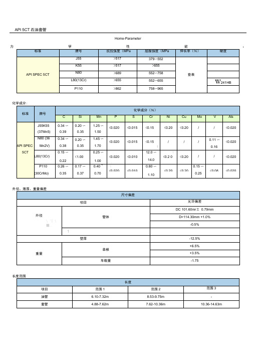
API 5CT石油套管Home-Parameter:力描油管述:标API SPEC 5CT、API SPEC 5B、ISO 11960准:用途:油管用于油井中抽取石油或天然气。
:注:P--平头;N--不加厚;U--外加厚;T&C--车螺纹带接箍;I--整体接头描述:石油套管标准:API SPEC 5CT、API SPEC 5B、ISO 11960:接箍 Coupling :1、 标准接箍 Stabdard Coupling2、 特殊间歇接箍 Special Space Coupling3、 特殊倒角接箍 Special Bevellde Coupling'i I \ \ .. - r -?1 f I4、 改进型带密圭寸环接箍 API Improved Seal-Ring Coupling(SR13)5、 组合接箍或异径接箍 Combination Coupling or Special Diameter Coupling短节或连接管 Pup Joint or Connector :包括所有油套管规格、螺纹或其他组合All Size,thread or their combination of tubing and casing are supplied.尺寸偏差 Dimensions and Tolerances外径、壁厚、重量允许偏差 Outside Diameter,Wall Thickness and Weight Tolerances:外径Outside Diameter管体Pipe BodyD< 101.60mr± 0.79mD< 114.30mr±+ 1.0%D-0.5%D接箍coupling ±1%D壁厚Wall Thickness 0,-12.5%t重量Weight 单根Single Lengths+ 6.5%-3.5% 车载量Carload Lots 0,-1.75%螺纹参数允许偏差Thread Parameter Tolerances品种规格Type and Size锥度tapermm/m螺距Pitch mm 齿高Heightmm螺纹角度Angle度deg.螺纹长度aLength L4(外螺纹ExternalThread)管端倒角Chamfer onEnd of Pipe度deg.紧密矩aStandoff每英寸Per Inch累计Accumulative管体螺纹PipeThread接箍螺纹CouplingThread圆螺纹油管Round ThreadTubing2 3/8"〜4 1/2" 10牙/英寸Threadsper inch+5.208-2.600±0.76 ±0.152+0.0511- I-0.10211/2 11/2P+5-0±11/2P ±11/2P 8牙/英寸Threadsper inch+5.208-2.600±0.76 ±0.152+0.051-0.10211/2 1P+5-0±1P ±1P圆螺纹套管Round Thread Casing 4" ~ 7" +5.208-2.600±0.76 ±0.152+0.051-0.10211/2 1P+5-0±1P ±1P偏梯形螺纹套管Buttress ThreadCasing4 1/2"〜7"接箍Coupling+4.50 --2.50±0.051 ±0.102 ±0.025 / -+5-0+11/2P-0+0-11/2P 完整螺纹Perfect thread+3.50-1.50不完整螺纹Lmperfectthread length+4.50-1.50注a:p--- 螺距Note 啊:p---Pitch.接箍料常用规格Normal size range of coupling stock代号Labels 外径OD( mm 壁厚WT(mmSpecificati onscoupling1.OD: 2-3/8"-20".2. Grade:J55 K55 N80 P110 ect.3. Thread :NU EU STC LTC BTC.4.Standard: API 5CT.-上、-, 「「product name : tubing coupling2.Standard: UL 6/ ANSI C80.1■.- I3.trade Size: 1/2" - 6"4.Surface: zinc plate on both out side and inner side , or hot dipped galvanzied and zinc plate on out side and zinc plate on innerside5. Material : seamless steel pipe6. Certificate: UL Listed, certificate No.E3082907. GeneralCoupling is manufactured from seamless steel pipe, and produced according to the standard of ANSI C80.1(UL6). We can produce hot-dipped galvanized at external surface and electro-galvanized at internal thread or electro-galvanzied totally . The coupling is used to connect the conduit to extend the length of the conduitUsage : This Rigid Conduit Coupling is used for RSC connection to extend the length of the conduitThreaded CouplingsTrade Size Standard Carton Qty Weight Per 100 pcs(Lbs) Outside Diameter "B" (in) Length1/2" 100 14 1.01 1-5/8"3/4" 50 20 1.25 1-41/641" 30 31 1.53 1-31/3;1-1/4" 25 39 1.87 2-1/32 1-1/2" 25 56 2.16 2-1/16 2" 20 73 2.65 2-1/8"2-1/2" 24 185 3.25 3-3/16 3" 16 226 3.87 3-5/16 3-1/2" 12 358 4.50 3-13/32 4" 10 400 4.88 3-33/64 5" Bulk 497 6.00 3-61/64 6" Bulk 816 7.20 4-1/4" The API couplings for tubing and casing pipesSize and Specifications For Tubing and Casing Couplings.Descriptions and size Type of Therad O.D*L(mm)Weight(kg)1.050 NUE 33.35*80.96 0.23 1.050 EUE 42.16*82.55 0.38 1.315 NUE 42.16*82.55 0.38 1.315 EUE 48.26*88.90 0.57 1.660 NUE 52.17*88.90 0.591.660 EUE 58.88*95.250.68Tubing Coupling1.900 NUE 55.88*95.25 0.561.900 EUE 63.50*98.42 0.842-3/8" NUE 73.02*107.95 1.282-3/8" EUE 77.80*132.82 1.552-7/8" NUE 88.90*130.18 2.342-7/8" EUE 93.17*133.35 2.403-1/2" NUE 107.95*142.88 3.713-1/2" EUE 114.30*146.05 4.104" NUE 120.65*146.05 4.354" EUE 127.00*152.40 4.824-1/2" NUE 132.08*155.58 4.894-1/2" EUE 141.30*158.75 6.054-1/2" STC 127.00*158.75 5.23 Casing Coupling4-1/2" LTC 127.00*177.80 4.154-1/2" BTC 127.00*225.42 4.555" STC 141.30*165.10 4.665" LTC 141.30*196.85 5.755" BTC 141.30*231.78 5.855-1/2" STC 153.67*171.45 5.23 5-1/2" LTC 153.67*203.20 6.42 5-1/2" BTC 153.67*234.95 6.36 6-5/8" STC 187.71*184.15 9.12 6-5/8" LTC 187.71*222.25 11.34 6-5/8" BTC 187.71*244.48 11.01 7" STC 194.46*184.15 8.39 7" LTC 194.46*228.60 10.83 7" BTC 194.46*254.00 10.54 7-5/8" STC 215.90*190.50 12.30 7-5/8" LTC 215.90*234.95 15.63 7-5/8" BTC 215.90*263.52 15.82 8-5/8" STC 244.48*196.85 16.23 8-5/8" LTC 244.48*254.00 21.67 8-5/8" BTC 244.48*269.88 20.86 9-5/8" STC 269.88*196.85 18.03 9-5/8" LTC 269.88*266.70 25.45 9-5/8" BTC 269.88*269.88 23.16 10-3/4" STC 298.45*203.20 20.78 10-3/4" BTC 298.45*269.88 25.74 11-3/4' STC 323.85*203.20 22.64 11-3/4' BTC 323.85*269.88 28.03 13-3/8" STC 365.12*203.20 25.66 13-3/8" BTC 365.12*269.88 31.77 16" STC 431.80*228.6 34.91 16" BTC 431.80*269.88 40.28 18-5/8" STC 508.00*228.60 51.01 18-5/8" BTC 508.00*269.88 62.68 20" STC 533.40*228.6 43.42 20" LTC 533.4*292.10 57.04 20" BTC 533.40*269.88 50.10。
FAW, FAW-C 与 FAW-C-T 型号空气暖气器、FCR 与 FCR-A 型号热转器、STW

INSTALLATION OPERATION ANDMAINTENANCE INSTRUCTIONSFAW, FAW-C & FAW-C-T TYPE AIRWARMERSFCR & FCR-A TYPE CONVECTORS STW & STW-T SAFE AREA AIR WARMERS HFT, AFT & SAT TYPE AIR THERMOSTATSPlease read these instructions thoroughly before installation and ensure theyare passed on to the end-userCONTENTS1.0 GENERAL 22.0 STORAGE 23.0 PRE INSTALLATION INSPECTION AND CHECKS 34.0 INSTALLATION 35.0 ELECTRICAL SUPPLY CONNECTION 46.0 EARTH CONNECTION 47.0 OPERATION 58.0 MAINTENANCE 59.0 MARKING 610.0 CERTIFICATION 6APPENDIX A – WIRING DIAGRAMS 7 APPENDIX B – HEATER GENERAL ARRANGEMENT DRAWINGS 18 APPENDIX C – ATEX/IECEx HAZARDOUS AREA CERTIFICATES 25To maintain the equipment warranty and the Hazardous Area Certification, the instructions contained within this manual must be complied with in full.1.0 GENERAL1.1 All work should be carried out by suitable qualified personnel.1.2 Carefully remove all protective packaging and visually inspect unit for any transit damage.1.3 Heaters must be handled with care and stored in dry conditions.1.4 CAUTION – Air warmers over 1m long are HEAVY and must be handled appropriately.•32kg FAW2000•38kg FAW2500•42kg FAW3000•up to 34kg FCR2•up to 49kg FCR31.5 Before connection ensure that the supply corresponds with that specified on the rating label. 1.6 Ensure that the sizes and types of cables to be used are suitably rated for the load andtemperature of the unit.1.7 Each heater must be protected by a suitably rated over current device.1.8 All prevailing rules, regulations and bylaws in force at the time and place of installation mustbe observed.1.9 The heater should be securely fixed in position and all terminal connections checked fortightness before energising.1.10 Any modification not carried out by Exheat Industrial Ltd will invalidate certification andwarranty.1.11 Refer to the relevant code of practice for the equipment:•IEC/EN 60079-14 for selection and installation•IEC/EN 60079-17 for inspection and maintenance of electric apparatus for use in potentially explosive atmospheres.1.12 All electrical testing must be carried out in a non-hazardous area.1.13 Precautions must be taken to prevent damage to machined surfaces and threads offlameproof enclosures.1.14 Ensure that any special conditions for safe use detailed on the Hazardous Area Certificationare complied with.2.0 STORAGE2.1 Store the equipment in an inside location that is dry, clean and well ventilated.2.2 Suitable preservation materials, such as silica gel bags or equivalent, have been placedinside the packaging. Additionally, spare silica gel bags, or equivalent, can be supplied by contacting Exheat Industrial Ltd.2.3 If the equipment is stored beyond 3 months, ensure that preservation materials are replaced.2.4 CAUTION – It is the client’s responsibility to ensure that, if the terminal enclosure is openedprior to installation, these bags are checked and replaced if necessary. When refitting terminal enclosure lid please ensure the gaskets are not damaged or moved in any way and for the HFT & AFT thermostats please refer to section 5.0 below.2.5 CAUTION– The following preservation instructions must be adhered to. Failure to do socould result in the equipment warranty being invalidated:•Store the equipment at between 0°C and +50°C.•Ensure that the equipment is not subjected to direct sunlight at ambient temperatures above +30°C.3.0 PRE INSTALLATION INSPECTION AND CHECKS3.1 Each heater and thermostat is manufactured to the highest standard with great care andquality materials. All the goods are thoroughly inspected and tested before leaving the manufacturing plant. They must be handled with care during storage and installation. Before the installation starts it is advised that the heater is checked to ensure the insulation resistance reading is above 2MΩ per element at 500 volts dc.3.1.1 Should the heater fail this test, isolate the power and control circuits (if installed), and followthe steps below:•Fill the terminal box with silica gel bags, and replace the terminal box lid.•Leave for 24hrs to draw any moisture out of the heater elements.•If you have a heated blanket, place this over the heater elements to help with the drying. Heater blankets are available to purchase from www.exheat-/contact/enquiry•If the insulation resistance has not been raised to a sufficient level after 24hrs, repeat the process above with replacement gel bags.•Should the above not raise the insulation resistance to the required level please contact the technical help on our website. www.exheat-/contact/support3.2Insulation Resistance (Megger)3.2.1 The ‘Megger’ should be applied between the phases and earth. A reading of greater than2MΩ at 500 volts dc should be recorded. Should the whole heater be below this value each element would need to be checked to ascertain which one was low in resistance.3.2.2 Use the continuity (Ohms) setting on the elements and check the resistance of each elementmatches or is approximately equal to the results as per the electrical test certificate that would have been sent with the heater.4.0 INSTALLATION4.1 Carefully remove the packaging from each item and check for damage. Immediately reportany damage to Exheat Industrial Ltd.4.2 The heater should be securely fixed in position using the pre-drilled fixing holes, and allterminal connections checked for tightness before energising.4.3 The appliance must be securely fitted to a wall or floor using only the brackets provided.4.3 The orientation of the heaters must be strictly adhered to with the feet facing down at alltimes.4.4 The installer or end user shall ensure that the unit has free and unrestricted air flow to allownatural convection to occur at all times. DO NOT COVER the heater and do not allow anything to rest on or against it. This could lead to dangerous overheating and will invalidate the hazardous area certification.4.5 At no time is the ambient temperature to be allowed to rise above +40°C (FAW & FAW-C T3& T4 variants) Or +60°C (T2 variants). This can be achieved by the use of Exheat Industrial Ltd integral (if option available) or separate flameproof air sensing thermostats (HFT & AFT type).4.6 The STW range may be regulated by an integral or separate industrial air sensing thermostat(SAT type)5.0 ELECTRICAL SUPPLY CONNECTION5.1 Refer to wiring diagrams in APPENDIX A.•The cable entries (1 x M20) in the FAW & STW Ranges are positioned to the side of the terminal box.•The cable entries (1 x M20) in the FCR are positioned on the bottom of the terminal box.•The cable entries (2 x M20) within the HFT and AFT are pre drilled and pre tapped. 5.2 No additional cable entries are to be made within any of the terminal boxes. Only ExheatIndustrial Ltd personnel can facilitate this.5.3 The cables must enter the FAW, FAW-C, FCR and FCR-A heaters via the terminal box cableentries using Ex e cable glands and IP Washers. The cables glands installed to the HFT & AFT thermostats are to be Ex d rated. All cable glands are to be suitable for the rating and size of the supply cables. For the STW Range heaters please use cable glands suitable for the power supply.5.4 Before connection ensure that the supply corresponds with that specified on the nameplatelabel.5.5 Ensure that the sizes and types of cables to be used are suitably rated for the load andtemperature of the unit.5.6 Each heater must be protected by a suitably rated over current device and earth leakagecircuit breaker device. See section 6 below for earthing connection details.5.7 The cables must enter the heater terminal box via suitably certified cable glands and IPwashers (not supplied) and be fitted by a qualified person. Any unused entries should remain plugged with the factory fitted certified Ex d plugs (if installed) or with suitably rated plugs and IP washers.5.8 The covers of the HFT & AFT terminal boxes are removed after releasing the 3 (AFT) or 4(HFT) socket head screws in the cover. When re-fitting ensure that the ‘O’ ring seal is in good condition and correctly located. The main cover mating and spigot faces MUST be kept clean and free from any debris at all times.5.8.1 The covers of the STW and FCR ranges can be removed by the unscrewing of the screws. 5.8.2 The covers of the FAW range can be removed by unscrewing the bolts around the outside ofthe lids.5.9 After re-fitting the lids on the HFT and AFT thermostats, the gap between the cover and thebody must be checked to ensure that it does not exceed 0.15mm.5.10 The installer or end user must connect to the Exheat Industrial Ltd supplied terminals withinthe terminal box - DO NOT connect to or disturb factory fitted wiring.5.11 WARNING – Silica gel bags must be removed before the heater is energised.6.0 EARTH CONNECTION6.1WARNING – these heaters MUST BE EARTHED.6.2 The external earth connections for the FAW and FCR ranges are located underneath theprotective guard in the same orientation as the elements. The external earth connections on the HFT & AFT ranges are on the lower corner.6.3 An internal earth connection is provided inside the terminal box.7.0 OPERATION7.1 Heat is generated by means of electric heating elements. Once energized the air warmerswill continue to operate until de-energized by an external (or integral) air thermostat.7.2 To adjust the temperature settings on an integral thermostat (HFT), Remove the lid (as persection 5.0) and rotate the adjustable control knob clockwise to increase the desired set-point or anti-clockwise to reduce the set-point.7.2.1 To adjust the temperature settings on an externally adjustable thermostat (AFT), Remove thelid (as per section 5.0) and rotate the adjuster clockwise (by use of a large flat blade screwdriver) to increase the desired set-point or anti-clockwise to reduce the set-point.7.3 The FAW and FCR ranges are designed to operate in ambient temperatures of up to +40°C(T3 & T4 rated units) and +60°C (T2 rated units) and the user must ensure that this temperature is not exceeded at any time.7.4 The STW air warmer range is designed to operate in ambient temperatures of up to +60°C.Where an integral adjustable thermostat is provided, this senses the ambient air temperature.Rotate the control knob clockwise to increase the set-point or anticlockwise to reduce the set-point.7.5 CAUTION– Check that the voltage on the heater nameplate is compatible with the mainssupply being used before energising the heater.8.0 MAINTENANCE8.1 All prevailing site safety regulations shall be adhered to at all times.8.2 Equipment shall be checked regularly for any dust accumulation which must be removed fromall surfaces.8.3 Before and whilst any maintenance activity is carried out, it must be ensured that there are nohazardous gases or dusts present.8.4 Equipment is to be fully isolated from the electrical supply before and whilst any work is beingcarried out.8.5 Any damage or faults should be notified to Exheat Industrial Ltd immediately.8.6 Any replacement parts required must be obtained directly from Exheat Industrial Ltd. The useof any other parts will void any certification and warranty.8.7 Equipment is certified for use in a hazardous area and reference should be made to IEC/EN60079-14 for selection and installation.8.7.1 IEC/EN 60079-17 for inspection and maintenance of electric apparatus for use in potentiallyexplosive atmospheres.In addition to the following recommendations:8.7.2 3 Monthly•Generally inspect the equipment for external damage or leaks.•Ensure that any spaces between the element fins, remains clear and that the airflow remains unrestricted.8.7.3 6 Monthly•Isolate the electrical supply and remove the cover (As section 5.0)•Internals should be clean and dry.•Ensure terminals are intact and secure.•Heating element insulation re sistance to be at least 2MΩ. Please refer to section 3.0 for further information•Refit cover with new gasket or ‘O’ ring if required (refer to section 5) and re-tighten using only the socket head screws provided.•Check the flamepath gap on the HFT & AFT Thermostats (As section 5.0)•Earth continuity must be maintained between all earth points and main structure.8.7.4 Annually•Carry out 3 monthly and 6 monthly checks as above.•Check for element failure or low insulation resistance, as section 3.08.8 Only Exheat Industrial Ltd can carry out rod type element replacements in hazardous areaheaters, any unauthorised modifications will invalidate the hazardous area certification and any warranty.8.9 If equipment is being left unused for a period greater than 3 months, carry out 6 monthlymaintenance before energizing.9.0 MARKINGS9.1 FAW, FAW-C & FCR Range:II 2 GEx e IlC T4 to T2 Gb9.2 FAW-C-T and FCR-A (with Integral Thermostat):II 2 GEx d e IlC T4 to T2 Gb9.3 HFT Type Thermostat used with Integral Thermostat Option, or Stand Alone type:II 2 GEx d IlC T6 Gb9.4 AFT Type Thermostat. (Stand Alone Externally Adjustable):II 2 G DEx d IlC T6 GbEx t IIIC T85°C Db10.0 CERTIFICATION10.1 FAW, FAW-C & FCR RangesATEX: LCIE 00 ATEX 6013 XIECEx: IECEx LCI 07 0009 X10.2 HFT Type Thermostat and AFT Type (Externally Adjustable)ATEX: LCIE 99 ATEX 6017 XIECEx: IECEx LCI 07 0003 X10.3 STW Range Air WarmersNo Certificates as these are Safe Area Heaters.10.4 SAT40 & SAT60No Certificates as these are Safe Area Thermostats.APPENDIX A, WIRING DIAGRAMSAPPENDIX B, HEATER GENERAL ARRANGMENT DRAWINGS.APPENDIX C, ATEX/IECEx HAZARDOUS AREA CERTIFICATES.EXHEAT INDUSTRIAL LTDThrexton House, Threxton Road Industrial EstateWatton, Thetford, IP25 6NGTel: +44 (0)1953 886210Fax: +44 (0)1953 883853For sales and new product information see our website2006/95/EC89/336/EEC(As amended by 92/31/EEC & 93/68/EEC)94/9/ECAuthor: P. BumsteadIssue Date: Feb. 2015Issue J_EnglishA4 printable version available on our website:/product48。
- 1、下载文档前请自行甄别文档内容的完整性,平台不提供额外的编辑、内容补充、找答案等附加服务。
- 2、"仅部分预览"的文档,不可在线预览部分如存在完整性等问题,可反馈申请退款(可完整预览的文档不适用该条件!)。
- 3、如文档侵犯您的权益,请联系客服反馈,我们会尽快为您处理(人工客服工作时间:9:00-18:30)。
Ceramic Resonators(Lead) FCR SeriesFEATURES•The FCR series are samll leaded ceramic resonators that used thickness shear mode or 3rd over tone thickness mode element of piezo ceramics with both 3.45 to 10.0MHz and 16.0 to50.0MHz.•The products with built-in capacitances have a dielectric element formed two capacities. This eliminates the external loading capacitors, thus simplifying circuit requirements.•Optimization of the temperature characteristics of both the piezoelectric materials and dielectric materials has resulted in stable oscillating frequency.•Ammo packing is available for various automatic insert machine (1500pieces/box). Short lead type and L-bend lead type are also available, please contact TDK.•Setting or matching of oscillating circuit condition which corre-spond to new models IC, application IC or custom IC are avail-able, please contact TDK.•The products don’t contain Lead at solder of internal joint and solder plating oflead wire. Y ou can use both Pb free solder (Sn-3Ag-0.5Cu) and Sn-Pb eutectic solder on your production.TEMPERATURE RANGESOSCILLATING FREQUENCY DRIFT OVER TEMPERATURE±0.3%/–40 to +85°C(Standard)OSCILLATING FREQUENCY AGING±0.3%/10years(Standard)SHAPES AND DIMENSIONSFCR∗∗.∗MC5FCR∗∗.∗M5BUILT-IN LOADING TYPE EXTERNAL LOADING TYPEPRODUCT IDENTIFICATIONS(1) Series name(2) Oscillating frequency(3) Production type and dimensions(4) Initial oscillating frequency tolerance(5) Oscillating frequency correlation(6) Loading capacitance(7) Products thickness(8) Packaging style and lead lengthConformity to RoHS DirectiveOperating/Storage–40 to +85°C FCR 4.0MC5(1)(2)(3)(4)(5)(6)(7) (8)FCR Ceramic resonator (lead)Symbol Oscillating frequency range Loading capacitors M5 3.45 to 10.0 MHz ExternalMC5 3.45 to 10.0 MHz InternalM616.0 to 50.0 MHz ExternalNon±0.5%±0.5%±0.5%A±0.3%±0.3%—Others Custom madeNon Non correlation for TDK StandardF Custom madeF1Custom madeF2Custom madeOthers Custom madeNon StandardN Custom madeOthers Custom madeSymbol Packaging style Lead length Non Bulk (500pieces)Standard(5mm) M Bulk (500pieces) 3.1mmM3Bulk (500pieces) 3.0mmTT aping(Ammo pack 16mm height,1500pieces)—T3T aping(Ammo pack 18mm height,1500pieces)—Others Custom made•Conformity to RoHS Directive: This means that, in conformity with EU Directive 2002/95/EC, lead, cadmium, mercury, hexavalent chromium, and specific bromine-based flame retardants, PBB and PBDE, have not been used, except for exempted applications.ELECTRICAL CHARACTERISTICS∗ ±0.5% is standard.• These values are typical. Application frequency are also available. Please contact TDK.RELIABILITY AND TEST CONDITIONSThe following test items are satisfied.(1) Oscillating frequency change: within ±0.25%(2) Resonant resistance change: within ±10Ω(3) Appearance, serious abnormalities not to exist.SOLDERABILITYThe lead wires are adopted Pb free plating wire to apply Pb free soldering. Y ou can also use current Sn-Pb eutectic solder.RECOMMENDED SOLDERING CONDITIONSThis is the fit product for flow soldering.FLOW SOLDERING CONDITIONPart No.Oscillating frequency Fosc(MHz)Resonant impedanceRo(Ω)Initial Fosc tolerance∗(%)Capacitance CL1/CL2(pF)FCR∗∗.∗MC5 type(Built-in loading type)FCR3.45MC5 3.4520±0.530/30 FCR3.52MC5 3.5220±0.530/30 FCR3.58MC5 3.5820±0.5/0.330/30FCR3.84MC5 3.8420±0.530/30 FCR4.0MC5 4.0020±0.5/0.330/30 FCR4.19MC5 4.1920±0.5/0.330/30 FCR5.0MC5 5.0020±0.5/0.330/30 FCR6.0MC5 6.0020±0.5/0.330/30 FCR8.0MC58.0030±0.5/0.320/20FCR10.0MC510.0030±0.5/0.320/20 FCR∗∗.∗M5 type(External loading type)FCR3.45M5 3.4520±0.5FCR3.52M5 3.5220±0.5FCR3.58M5 3.5820±0.5/0.3FCR3.64M5 3.6420±0.5FCR4.0M5 4.0020±0.5/0.3FCR4.19M5 4.1920±0.5/0.3FCR5.0M5 5.0020±0.5/0.3FCR6.0M5 6.0020±0.5/0.3FCR8.0M58.0030±0.5/0.3FCR10.0M510.0030±0.5/0.3FCR∗∗.∗M6 type(External loading type)FCR16.0M616.0040±0.5FCR18.0M618.0040±0.5FCR18.43M618.4340±0.5FCR24.0M624.0040±0.5FCR33.86M633.8640±0.5FCR40.0M640.0040±0.5T est items T est conditionsLow temperature storage characteristics T emperature: –40±3°C Time: 1000hHigh temperature storage characteristics T emperature: +85±2°C Time: 1000hHumidity resistance Humidity: 90 to 95(%)RH T emperature: 60±2°C Time: 100hThermal shock–40°C (30min), 85°C (30min) x 100 cycles Soldering heat resistance Solder temperature: peak 260°C, 10s flowDrop Drop 3 times onto the concrete from a height of 1mVibration Frequency: 10⇔ 55⇔ 10Hz/minAmplitude: 1.5mmX, Y and Z directions for 2h eachT est conditions T est resultWith Rosin-ethanol 25% by weight,dip in Sn-Pbeutectic solder bath at 230±5°C for 3±0.5sec. orPb free solder(Sn-3Ag-0.5Cu) bath at 245±2°Cfor 3±0.2sec.95% minimum ofsurface should becovered by new solder.Heat-resistant temperature260±5°CHeat-resistant time10±1sec.Number of times1time。