Microfluidics and Microtechnology for Microreactor Systems
Investigation of Microfluidics and Heat Transferability Inside a Microreactor Array Made of Glass

265
(1)
with: k: heat transfer coefficient [W/m2K]; (~Q/~t)R-K: heat flow [W]; A: heat transfer surface [m2]; ~ T m: mean logarithmic temperature difference [K] The mean logarithmic temperature difference arises from the measured temperatures of the coolant and the reactants both at the inlet and outlet ofthe micro reactor (equation 2).
microreactor
product collection
Fig. 2:
scheme of experimental set-up for calorimetric measurements
The heat transfer between the reaction channels and their vicinity was described by the heat transfer coefficient which was calculated from equation (1):
264
Spatially resolved information on heat transferability and simultaneous mapping of the entire process were obtained by thermographic measurements of exothermicities in the micro reactor array applying an infrared camera system. Finally, Computational Fluid Dynamic (CFD) simulations were carried out to investigate the influence of flow and mixing behavior on heat flow and heat transfer.
Microfluidics of nano-drug delivery
Microfluidics of nano-drug deliveryClement Kleinstreuer a,b,*,Jie Li a ,Junemo Koo caDepartment of Mechanical and Aerospace Engineering,North Carolina State University,Raleigh,NC 27695-7910,USA bDepartment of Biomedical Engineering,North Carolina State University,Raleigh,NC 27695-7910,USA cDepartment of Mechanical Engineering,Kyung Hee University,Seocheon-dong,Gyeonggi-do 446-701,South Koreaa r t i c l e i n f o Article history:Received 12December 2007Received in revised form 4April 2008Available online 12June 2008Keywords:Bio-MEMS Drug delivery Nanofluids Microfluidics Microchannela b s t r a c tAfter a brief review of microfluidics,a bio-MEMS application in terms of nanofluid flow in microchannels is presented.Specifically,the transient 3-D problem of controlled nano-drug delivery in a heated micro-channel has been numerically solved to gain new physical insight and to determine suitable geometric and operational system puter model accuracy was verified via numerical tests and com-parisons with benchmark experimental data sets.The overall design goals of near-uniform nano-drug concentration at the microchannel exit plane and desired mixture fluid temperature were achieved with computer experiments considering different microchannel lengths,nanoparticle diameters,channel flow rates,wall heat flux areas,and nanofluid supply rates.Such micro-systems,featuring controlled transport processes for optimal nano-drug delivery,are impor-tant in laboratory-testing of predecessors of implantable smart devices as well as for analyzing pharma-ceuticals and performing biomedical precision tasks.Ó2008Elsevier Ltd.All rights reserved.1.IntroductionMicrofluidics is the study of transport processes in microchan-nels,i.e.,methods and devices for controlling and manipulating fluid flow and particle transport at the microscale.Microfluidic de-vices,consisting in general of reservoirs,channels,pumps,valves,mixers,actuators,filters and/or heat exchangers,are primary com-ponents of lab-on-a-chip and total analysis systems [1]or function as bio-MEMS for precise drug delivery by implanted or transder-mal rger versions may be used as micro-heat sinks in miniature electronic systems (see Kleinstreuer and Li,[2]).The basics of microfluidics are discussed in the books by Tabeling [3]and Nguyen and Wereley [4],while bio-MEMS fundamentals,technologies,and applications for drug delivery have been re-viewed by Tay [5]as well as in selected chapters by Saliterman [6]and Wang and Soper [7].Beebe et al.[8]summarized the phys-ics and applications of microfluidics in biology,discussing micro-device components as well as manufacturing methods,such as micromachining,soft lithography,embossing,in situ construction,injection molding,and laser ablation.As Beebe et al.[8]illustrated,the main component in any microfluidic device is the channel network.Bio-MEMS can be considered as having at least one system dimension in the submicron or micron range (100nm–200l m)and other dimensions of up to several millimeters [6].With the increasing awareness of microfluidic physics and the surface sci-ence of building materials,such as silicon,polymers,glass and ceramics,the traditional fabrication techniques previously im-ported from integrated circuit manufacturing to MEMS have been also applied to bio-MEMS.The central question in microfluidics modeling is the validity of the continuum assumption,and if so (as may be the case for standard water flow in microchannels with D h >0.1l m),which are the dominant forces?Important character-istics and phenomena in the microscale environment include lam-inar flow,entrance effects,surface roughness effects,diffusion,wall forces,surface tension,very high surface-area-to-volume ra-tio,and microfluidic resistance.For example,some experimental evidence indicates that the Reynolds number for transition from laminar to turbulent flow may be different in microchannels from that predicted by macrochannel-flow theory.Indeed,recent works analyzed by Koo and Kleinstreuer [9]showed that a lot of contro-versy exists between experimental reports on (thermal)microscale flows,explaining that surface roughness and entrance effects may cause early turbulence.In the 1990s most bio-MEMS studies were concentrated in aca-demia,while in recent years commercialization of such devices be-gan.Examples include an electronically activated drug delivery microchip (Shawgo et al.,[10]);a controlled delivery system via integration of silicon and electroactive polymer technologies;a MEMS-based DNA sequencer developed by Cepheid [11];and0017-9310/$-see front matter Ó2008Elsevier Ltd.All rights reserved.doi:10.1016/j.ijheatmasstransfer.2008.04.043*Corresponding author.Address:Department of Mechanical and Aerospace Engineering,North Carolina State University,Raleigh,NC 27695-7910,USA.Tel.:+19195155261;fax:+19195157968.E-mail address:ck@ (C.Kleinstreuer).International Journal of Heat and Mass Transfer 51(2008)5590–5597Contents lists available at ScienceDirectInternational Journal of Heat and Mass Transferjournal homepage:www.else v i e r.c o m /l o ca t e /i j h mtarrays of in-plane and out-of-plane hollow micro-needles for der-mal/transdermal drug delivery (Ovsianikov et al.,[12]and Kimand Lee,[13]among others)as well as nanomedicine applications of nanogels or gold-coated nanoparticles (Labhasetwar and Leslie-Pelecky,[14]).Part of the advanced endeavors in developing inte-grated micro-or nano-drug delivery systems is the interest in eas-ily monitoring and controlling target-cell responses to pharmaceutical stimuli,to understand biological cell activities,or to facilitate drug development processes.While micro-devices allow precise drug delivery by both im-planted and transdermal techniques,conventional drug delivery is characterized by the ‘‘hill-and-valley”phenomenon.It implies that when a drug is dispensed,drug concentration in the blood will increase,peak and then drop as the drug is metabolized,where the cycle is repeated for each drug dose.In nano-drug delivery (ND)systems,controlled drug release occurs over an extended period of time.Hence,the desired drug concentration will remain within the therapeutic window as ually,an integrated ND sys-tem is composed of drug preparation,feeding,sensing (test),and feedback parts.The types and doses of drugs are selected in the drug preparation part,while the feeding system guides drugs and buffer fluids into the test part.Test cells are placed into the test section,where they react to drugs and resulting (electric)response signals are monitored via the feedback part.Of interest here is the optimal delivery of nanoparticles (drugs)in an aqueous solution in terms of predetermined uniform particle concentration and mixture temperature.Such a dilute suspension,called a nanofluid,is conveyed via microchannels to recipient liv-ing cells situated in a well (see Fig.1a ).Controlled dosages of nano-drugs allow for simultaneous testing of living cells and stim-uli responses.Those micro-systems,featuring controlled transport processes for optimal nano-drug delivery,are important in labora-tory-testing of predecessors of implantable smart devices which may offer closed-loop sensing,result interpretation,and automatic nano-drug dispensation.Other applications for this basic microflu-idic device include testing of pharmaceuticals and performing effi-cient biomedical analyses.2.TheoryIn the controlled multiple nano-drug-stream system (Fig.1a ),the plenum chamber functions as a reservoir of an aqueous nutri-ent-supply and/or purging fluid.The microchannels can alter the incoming fluid to the test section,i.e.,target-well with living cells,by adjusting the individual inlet pressure or resistance.Nano-drugs can be supplied by setting the supply pressure of the nano-drug solution higher than that of the fluid supply side,while purging fluid can go through the testing section by lowering or eliminating the drug supply pressure.An appropriate wall heat flux beneath the microchannels ensures that delivery of the drug-fluid mixture to the living cells occurs at an optimal temperature,i.e.,37°C.DueMultiple microchannels(Attached to wells with cells)Surface heatingPlenum chamber(Reservoir)Buffer fluid inletVariable nano-drug inlets(Nanofluid)Fig.1a.Nanomedicine delivery system with eight microchannels.Nomenclature A g geometric area A v valid area c concentrationc p specific heat capacityd diameterD diffusivity coefficient D h hydraulic diameter H channel heightk thermal conductivity L channel length Nu Nusselt number p pressurePo Poiseuille number Pr Prandtl number q 00uniform heat fluxR b interface thermal resistance Re Reynolds number Ttemperaturet timeu ,v velocity components Wchannel widthGreek symbolsaaspect ratiou volume fraction j B Boltzmann constant l dynamic viscosity m kinematic viscosity q density v Reynolds number ratioSubscripts eff effective f base fluid pparticleFig.1b.Representative microchannel with controlled nanofluid injection.C.Kleinstreuer et al./International Journal of Heat and Mass Transfer 51(2008)5590–55975591to the temperature dependentfluid properties,i.e.,viscosity,den-sity,diffusivity and thermal conductivity,the heatflux was also as-sumed to have an influence on the drug concentration and velocity distribution.Selecting one representative microchannel,the cho-sen unit has a hydraulic diameter of40l m for the main channel and20l m for the drug inlet branch.The Reynolds number ratio of drug-inlet to main-channelflows is defined asv¼Re2=Re1ð1ÞThe associated Reynolds numbers areRe i¼ðuD hÞim ið2Þwith i=1indicating the purging or nutrient-supply channel and i=2denoting the nanofluid channel(see Fig.1b).The drug concentration distribution for different main-channel lengths and inlet Reynolds numbers was analyzed.The effects of the Reynolds number ratio,v,and thermal boundary condition, q wall,were also compared and analyzed.Both the purging/nutri-ent-supplyfluid and nano-drug solution were at inlet room tem-perature(T in=293K).2.1.Nanofluid property correlationsTo evaluate the impact of nanoparticles(i.e.,drugs)and wall heatflux on the velocityfield as well as temperature and concen-tration profiles,the nanofluid properties have to be identified.Typ-ically,for a very dilute suspension,the effective viscosity,density and specific heat capacity have the following forms(Xuan and Roetzel,[15]):l eff ¼l f1ð1ÀÞð3Þqeff¼uq pþð1ÀuÞq fð4Þðq c pÞeff¼uðq c pÞpþð1ÀuÞðq c pÞfð5ÞHere,q eff is the nanofluid density,l eff is the nanofluid viscosity,and (q c p)eff is the nanofluid specific heat capacity.The nanoparticle dif-fusivity follows the Stokes–Einstein equation:D¼j B Tpl pð6Þwhere j B is the Boltzmann constant,T is thefluid temperature,and d p is the nanoparticle diameter.Most challenging is the thermal conductivity of nanofluids,for which benchmark experimental data sets show that the thermal conductivity of a nanofluid has strong volume fraction as well as temperature dependences(Das et al.,[16];Li and Peterson,[17]). Some researchers introduced different effective thermal conduc-tivity theories which directly or indirectly considered temperature dependence,e.g.,Koo and Kleinstreuer[18],Prasher et al.[19],and Jang and Choi[20].In comparison studies,Kleinstreuer and Li[21] and Li and Kleinstreuer[22]analyzed the models of Jang and Choi [20]and Prasher et al.[19],and updated their KKL(Koo–Kle-instreuer–Li)model.The KKL model is based on Brownian-mo-tion-induced micro-mixing and achieved good agreements with various experimental data sets.Specifically,the KKL thermal con-ductivity model,k eff,takes into account the effects of particle size, particle volume fraction and temperature dependence as well as the type of nanoparticle and basefluid combinations in form of (Koo and Kleinstreuer,[9]):k eff¼k staticþk Brownianð7ÞThe static part is from Maxwell’s model and the dynamic part was developed based on kinetic theory together with Stokes’flow of mi-cro-scale convective heat transfer,i.e.,micro-mixing.Hence,k statick f¼1þ3k p;effk fÀ1uk p;effk fþ2Àk p;effk fÀ1uð8Þandk Brownian¼5Â104uq f c p;fffiffiffiffiffiffiffiffiffiffiffijbTqpd psg T;u;d p;q pð9Þwhere q is the density,c p,f isfluid thermal capacity,and u is the vol-ume fraction,while the subscripts f and p indicatefluid and particle, respectively.The g-function,determined semi-empirically,was introduced to encapsulate the thermo-hydrodynamic interactions among all nanoparticles and affected micro-scalefluid parcels.For Al2O3–water and CuO–water nanofluids,the nonlinear g-function generated r2values of96%and98%,respectively(Li,[23]).The KKL model was employed in the current study.erning equationsAssuming the continuum approach to be valid(i.e.,here D h P20l m)for transient3-D laminar incompressibleflow in a microchannel,the continuity,momentum,energy and species transfer equations have to be solved,considering temperature-dependentfluid properties(see Section2.1).Continuity equationrÁ½qðTÞ~u ¼0ð10ÞMomentum equationo uo tþð~uÁr~uÞ¼À1q r pþrÁðm r~uÞð11ÞEnergy equationq c p o Tþð~uÁrÞT!¼r2ðkTÞþl Uð12ÞwhereU¼o u io x jþo u jo x io uio x jð13ÞMass transfer equationo co tþ~uÁr c¼D r2cð14ÞHere,~u is the velocity vector,D is the nanoparticle diffusivity,and U is the viscous dissipation function.For nanofluidflow and purefluid flow,the corresponding physical properties will be chosen,i.e.,the thermal conductivities,k eff and k f,respectively.For the design analysis,uniform inlet velocity conditions and an ambient pressure condition for the outlet were applied.A5% volume fraction of d p=10and500nm nanoparticles in water was selected to enter the drug supply channel in the form of a rectangular pulse function.The cycle,shows as part of Fig.1b,is centered with basically a one-second pulse during the observation time t T=30s.It starts at dimensionless time t*=0.49,which is defined astüt=t T;06tÃ61ð15Þwhere t T=L max/u1is the pulse period,and t is the real time,whileL max=10mm being the maximum length used,and u1¼m1Re1D h1.A heatflux variable in magnitude and extent was applied along part of the bottom wall,starting at z=0.02mm and ending selectively at z=2.5,3,4or5mm(see Fig.1b).5592 C.Kleinstreuer et al./International Journal of Heat and Mass Transfer51(2008)5590–55972.3.Numerical methodThe numerical solution of the Eulerian transport equations were carried out with a user-enhanced,unstructuredfinite-volume based program,i.e.,CFX11from Ansys,Inc.(Canonsburg,PA). The mesh size of the computational domain used in this study was refined until acceptable levels of grid independence of the solutions were achieved.Furthermore,both the maximum mass and momentum residuals were less than10À4.3.Results3.1.Model validationsClassical friction factor correlations as well as k eff-comparisons are discussed.Specifically,for laminar fully-developedflow of a purefluid,the Poiseuille number is defined asPo¼fRe¼D pÁD2h2l f uLð16Þwhere Po=16for circular conduits.3.1.1.Friction factorFor rectangular microchannels,the Poiseuille number is a func-tion of aspect ratio(a=channel width/channel height).It can be determined using Eq.(17)from Shah and London[24].Po¼241À1:3553aþ1:9467a2À1:7012a3Àþ0:9564a4À0:2537a5Áð17Þwhere for square ducts,Po=14.23.Fig.2provides a comparison of friction factors at different Reynolds number.Clearly,the computed friction factor is in very good agreement with the theoretical re-sults.With an increase in inlet velocity,the temperature range and average temperature in thefluid decreases,i.e.,from304K to 296K,and thefluid kinematic viscosity increases.Thus,for thesame velocity,the Reynolds number,Re1¼ðuD h mÞ1is different for water with temperature-dependent properties when compared to constant properties.The reason is that the bottom heatflux influ-ences the temperature distribution and,via the changingfluid prop-erties,also the velocityfield,especially where the temperature difference is large.The inset plot in Fig.2indicates the friction fac-tor differences between water with temperature-dependent prop-erties and constant properties for the same velocity.Specifically,e¼f c:pÀf v:pÀÁf c:pð18Þwhere f c.p is the friction factor for water with constant properties, f v.p is the friction factor for water with variable properties,i.e.,tem-perature dependent.In the lower velocity range,the higherfluid temperature induced a lower kinematic viscosity for the tempera-ture-dependentfluid which introduced a higher Reynolds number and hence a smaller friction factor.As the velocity increases,the friction factor increases because of the decrease in thefluid’s aver-age temperature.Fig.3a and b show the axial velocity distribution at the channel outlet for water with temperature-dependent and constant properties,respectively.As Fig.3a indicates,the tempera-ture generated a decrease in viscosity near the bottom surface and as a result lowers the location of the maximum velocity,while for water with constant properties the maximum velocity always ap-pears at the centerline(see Fig.3b).3.1.2.Pressure gradientLi and Kleinstreuer[22]analyzed the influence of nanoparticle volume fraction on the pressure gradient for fully-developedflow. Selecting nanofluids with4%volume fractions of28.6nm CuO–water mixtures,the pressure gradient increased an average13% for a constantflow rate,which matched measured data.Fig.4de-picts the pressure gradients at different mean velocities when employing a5%gold-particle-and-water mixture with differentFig.3.Velocity distribution in channel outlet(a)water with temperature dependent properties and(b)water with constant physical properties.C.Kleinstreuer et al./International Journal of Heat and Mass Transfer51(2008)5590–55975593nanoparticle sizes,i.e.,10and500nm(see Labhasetwar&Leslie-Pelecky,[14]).Clearly,nanoparticle size does not influence the pressure gradient when the same volume fraction is employed (see Eqs.(3)–(5)).The pressure gradient increases by13–18%when employing the5%nanofluids,confirming the results of Li and Kle-instreuer[22].3.1.3.Enhanced thermal conductivityIn Fig.5,the KKL model is compared with experimental data for CuO–water nanofluid at different temperatures(21°C,36°C,51°C) and volume fractions(1–4%).The KKL model compares well with the experimental observations of Das et al.[16].Because of the lack of quantitative information concerning therapeutic nanoparticles, other than their mean diameters,the practical range for k eff/k f was assumed to be1.0–2.5and the g-function was taken to be lin-early dependent on temperature(20–70°C),generating a value range for g of0.3Â10À3to7Â10À3.3.2.Concentration distributions of drug nano-particlesThe distributions of nanoparticle concentrations and tempera-tures at the main microchannel outlets with variable channel lengths were compared for different particle sizes and boundary conditions,i.e.,different Reynolds numbers Re1and Re2and for dif-ferent Reynolds numbers ratios v as well as different heating modes q w.The desired nano-drug particle uniformity at z=L is de-fined asU c¼A v=A gÂ100%ð19Þwhere A v is the valid area,i.e.,the area where the drug particle con-centration is equal or larger than90%of local maximum concentra-tion,and A g is the actual geometric channel-exit area.Fig.6 compares the dimensionless drug concentration distributions (d p=10nm)at different cross sections in the microchannel for dif-ferent paring the U c(t)graphs for the outlet cross section at z=10mm,it is evident that the added heat measurably increases nanoparticle diffusion D¼j B T3pl d pand hence the drug distribution two-fold,i.e.,via the mixture temperature and the reducedfluid vis-cosity.At station z=3mm,the nanoparticles are still concentrated in a small part of the channel cross section and hence the drug uni-formity U c is very low.Clearly,nanoparticle(i.e.,drug)mixing develops as the two streams merge,and for z=10mm the desired near-uniform concentration profile is achieved.There,the differ-ence is less than10%between the maximum value and the mini-mum value in the particular cross section.Figs.7a–d and8a–d depict the velocity and dimensionless nano-drug concentration distributions along the center line (À2Â10À56y62Â10À5)at threeflow-developing phases (z=0.5mm,5mm and10mm)at different time levels for the case of v=1.69and L=10mm.The dimensionless nano-drug concen-tration is defined as:cüc=c0ð20Þ5594 C.Kleinstreuer et al./International Journal of Heat and Mass Transfer51(2008)5590–5597here c is the local drug concentration,and c0is the drug concentra-tion at the drug-channel inlet,which is assumed to be unity.The intensity of drug supply measurably influences the velocity distribution(Fig.7).At t*=0.51,in the middle of nanofluid injec-tion,the main-channel velocity is at a maximum.The velocity down stream of z>0.5mm is somewhat elevated because of the nano-drug influence(see Fig.8a).For the same reason,at t*=0.68and t*=0.85,the velocity distribution exhibits the lowest values at z=5mm and z=10mm,respectively(Fig.7b and c).At t*=1.0,most of the nano-drug particles supplied have left the delivery microchannel and hence the velocity distributions at the three axial stations(i.e.,z=0.5,5,and10mm)exhibit no differ-ences any more(Fig.7d).At the middle of the one-second nanofluid cycle(i.e.,t*=0.51), the resulting nano-drug pulse is registered near the inlet at z=0.5mm but is not felt further downstream(Fig.8).The nanoparticles diffuse and they are conveyed through the channel leading to highly nonlinear‘‘time-and space-”dependent concen-tration profiles(Fig.8a–d).For example,at t*=0.85the nano-drug distribution is almost uniform across the channel exit plane(see Fig.8c).Fig.9compares the uniformity of drug-particle concentration at different Re1numbers and microchannel lengths.With the de-crease of Re1values from0.04to0.004and with an increase of the channel length,which implies much larger diffusion times, the uniformity of drug-particle distribution improves.As expected, at small Reynolds numbers,drug uniformity can be much more rapidly achieved.Fig.10depicts the drug uniformity at channel outlet z=10mm for drugs with a particle diameter of500nm at different Reynolds numbers.It shows that the decrease of Re1can improve drug parison of Figs.10and6shows that smaller drug-par-ticles may greatly benefit the drug concentration uniformity.Figs.11and12summarize the percentage changes in minimum microchannel-length in order to achieve near-uniform exit concen-tration for different Reynolds number ratios and different wall-heat-flux extents,respectively.The‘‘minimum uniformity-length”is defined as the required main-channel length where the drug-particle concentration in the exit area is equal or larger than90% of the local maximum concentration.Selecting v=1.26as the ref-erence ratio,the dimensionless minimum uniformity length change is compared for different Reynolds number ratios in Fig.11,an increase of v measurably decreases the minimum uni-formity length.As Fig.12shows,a decrease of the heated area also decreases the minimum uniformity length.Because thefluid tem-perature increase isfixed(from room temperature293K to bodyC.Kleinstreuer et al./International Journal of Heat and Mass Transfer51(2008)5590–559755955596 C.Kleinstreuer et al./International Journal of Heat and Mass Transfer51(2008)5590–5597temperature 310K),the effect on the drug diffusivity is not prom-inent by just decreasing the heated area.4.ConclusionsIn the present study a nano-drug-supply system,i.e.,a bio-MEMS,was introduced.Of main interest were the conditions for achieving uniform concentrations at the microchannel exit of the supplied nano-drugs.A heat flux which depends on the levels of nano-fluid and purging fluid velocity was added to en-sure that drug delivery to the living cells occurs at an optimal temperature,i.e.,37°C.The added wall heat flux had also a po-sitive influence on drug-concentration uniformity.Overall,thenano-drug concentration uniformity is influenced by channel length,particle diameter and the Reynolds number of both the nanofluid supply and main microchannels.In light of the convec-tion–diffusion controlled transport mechanisms,longer channels,smaller particle diameters as well as lower Reynolds numbers are desirable for best,i.e.,uniform drug delivery.Furthermore,the Reynolds number ratio and the extent of heated area also measurably influence the minimum microchannel length re-quired for achieving the desired drug-concentration uniformity.Future work will focus on the effects of angled drug-delivery channel and static mixer in the main channel.AcknowledgementThe support of Jie Li via an endowed fellowship created by Joe and Sarah Archie as well as the use of ANSYS-CFX11(Ansys,Inc.,Canonsburg,PA)are gratefully acknowledged.References[1]H.A.Stone, A.D.Stroock, A.Ajdari,Engineering flows in small devices:microfluidics toward a lab-on-a-chip,Annu.Rev.Fluid Mech.36(2004)381–411.[2]C.Kleinstreuer,J.Li,in:D.Li (Ed.),Microscale Cooling Devices,Encyclopedia ofMicro and Nanofluidic,Springer-Verlag,Heidelberg,DE,2008.[3]P.Tabeling,Introduction to Microfluidics,Oxford University Press,Oxford,UK,New York,2005.[4]N.-T.Nguyen,S.T.Wereley,Fundamentals and Applications of Microfluidics,Arten House,Boston,2006.[5]F.E.H.Tay,Microfluidics and Biomems Applications,Kluwer AcademicPublishers,Boston,2002.[6]Steven S.Saliterman,Fundamentals of BioMEMS and Medical Microdevices,Wiley-Interscience SPIE PRESS Bellingham,Washington,USA,2006.[7]W.Wang,S.A.Soper,Bio-MEMS:Technologies and Applications,CRC/Taylor &Francis,Boca Raton,2006.[8]D.J.Beebe,G.A.Mensing,G.M.Walker,Physics and applications ofmicrofluidics in biology,Annu.Rev.Biomed.Eng.4(2002)261–286.[9]J.Koo, C.Kleinstreuer,Liquid flow in microchannels:experimentalobservations and computational analysis of microfluidics effect,J.Micromech.Microeng.13(2003)568–579.[10]R.S.Shawgo,A.C.R.Grayson,Y.Li,M.J.Cima,Bio-MEMS for drug delivery,Curr.Opin.Solid State Mater.Sci.6(2002)329–334.[11]Cepheid,<>,2003.[12]A.Ovsianikov,B.Chichkov,et al.,Two photon polymerization of polymer–ceramic hybrid materials for transdermal drug delivery,Int.J.Ceramic Technol.4(2007)22–29.[13]K.Kim,J.B.Lee,High aspect ratio tapered hollow metallic microneedle arrayswith microfluidic interconnector,Microsyst.Technol.13(2007)231–235.[14]bhasetwar, D.L.Leslie-Pelecky,Biomedical Applications ofNanotechnology,Wiley-Interscience,A John Wiley &Son,Inc.,Publication,2007.[15]Y.Xuan,W.Roetzel,Conceptions for heat transfer correlation of nanofluids,Int.J.Heat Mass Transfer 43(2000)3701–3707.[16]S.K.Das,N.Putra,P.Thiesen,W.Roetzel,Temperature dependence of thermalconductivity enhancement for nanofluids,J.Heat Transfer 125(2003)567–574.[17]C.H.Li,G.P.Peterson,Experimental investigation of temperature and volumefraction variations on the effective thermal conductivity of nanoparticle suspensions (nanofluids),J.Appl.Phys.99(2006)084314.[18]J.Koo,C.Kleinstreuer,A new thermal conductivity model for nanofluids,J.Nanoparticle Res.6(2004)577–588.[19]R.S.Prasher,P.Bhattacharya,P.E.Phelan,Brownian motion based convectiveconductive model for the effective thermal conductivity of nanofluids,J.Heat Transfer 128(2006)588–595.[20]S.P.Jang,S.U.S.Choi,Effects of various parameters on nanofluid thermalconductivity,J.Heat transfer 129(2007)617–623.[21]C.Kleinstreuer,J.Li,Analysis of the Jang &Choi k eff -model,ASME J.HeatTransfer 130(2008).[22]J.Li,C.Kleinstreuer,Thermal performance of nanofluid flow in microchannels,Int.J.Heat Fluid Flow,29(2008),in press.[23]J.Li,Computational Analysis of Nanofluid Flow in Microchannels withApplications to Micro-heat Sinks and Bio-MEMS,Ph.D.dissertation,MAE Department,NCSU,Raleigh,NC,2009.[24]S.K.Shah,A.L.London,Laminar Flow Forced Convection in Ducts,Supplement1to Advances in Heat Transfer Academic,New York,1978.C.Kleinstreuer et al./International Journal of Heat and Mass Transfer 51(2008)5590–55975597。
Microreactors
Unequal height causes pressure drop and non-uniform velocity – non-uniform zeta potential of the channel
Non-uniform zeta potential may give rise to adsorption of analytes on the channel
Schematic diagram of the microchip system for sample introduction and detection.
24
Catalytic reactions - Suzuki
Байду номын сангаас
Reaction scheme for the coupling of 4-bromobenzonitrile and phenylboronic acid in a microreactor under EOF
Daniel et.al Chem comm 2005
23
Interface-syringe flow and EOF
This had an error percentage ranging from 1 to 20%. Because the hydrodynamic flow is insensitive to electrophoretic mobility, this electrophoresisbased microchip device was free of injection bias due to different ionic strength and electrophoretic mobility in the sample.
微流控水凝胶原理英文
微流控水凝胶原理英文Microfluidic Hydrogel PrinciplesMicrofluidics is a rapidly growing field that has revolutionized various aspects of scientific research and technological advancements. One particularly intriguing application of microfluidics is the development of water-based hydrogels, which have gained significant attention due to their unique properties and versatile applications. In this essay, we will explore the fundamental principles underlying the formation and behavior of microfluidic hydrogels.Hydrogels are three-dimensional polymeric networks that can absorb and retain large amounts of water, making them highly hydrophilic and swellable. These materials possess a remarkable ability to mimic the extracellular matrix of living tissues, making them particularly useful in biomedical applications such as tissue engineering, wound healing, and drug delivery. Microfluidic technology has enabled the precise control and manipulation of these hydrogel systems at the microscale, leading to the emergence of microfluidic hydrogels.The formation of microfluidic hydrogels is typically achieved throughthe use of microfluidic devices, which are designed to precisely control the flow and mixing of various precursor solutions. These precursor solutions typically consist of polymers, crosslinking agents, and other additives that can undergo chemical or physical crosslinking reactions to form the hydrogel structure. The microfluidic platform provides a highly controlled and reproducible environment for the hydrogel formation, allowing for the creation of complex and intricate hydrogel structures with precise control over their size, shape, and internal architecture.One of the key principles underlying the formation of microfluidic hydrogels is the concept of laminar flow. In microfluidic devices, the flow of liquids is typically characterized by laminar flow, where the fluid layers move in parallel, with little to no turbulence or mixing between them. This laminar flow regime enables the precise control and manipulation of the hydrogel precursor solutions, allowing for the formation of well-defined hydrogel structures.The process of microfluidic hydrogel formation typically involves the following steps:1. Mixing of precursor solutions: The microfluidic device is designed to facilitate the controlled mixing of the hydrogel precursor solutions, such as polymers and crosslinking agents. This mixing can be achieved through the use of microfluidic channels, junctions, or otherspecialized geometries.2. Crosslinking and gelation: As the precursor solutions mix, the crosslinking reaction is initiated, leading to the formation of the hydrogel network. The crosslinking can be triggered by various mechanisms, such as chemical reactions, physical interactions, or environmental stimuli (e.g., temperature, pH, or light).3. Encapsulation and patterning: The microfluidic platform allows for the encapsulation of various materials, such as cells, drugs, or other functional components, within the hydrogel matrix. Additionally, the laminar flow regime enables the patterning of hydrogel structures with high spatial resolution, leading to the creation of complex and customizable hydrogel architectures.The unique properties of microfluidic hydrogels, such as their high surface-to-volume ratio, tunable mechanical properties, and ability to mimic the extracellular environment, make them highly versatile for a wide range of applications. These applications include tissue engineering, where microfluidic hydrogels can be used to create 3D cell culture models that closely mimic the in vivo microenvironment. In drug delivery, microfluidic hydrogels can be designed to encapsulate and release therapeutic agents in a controlled and targeted manner. Additionally, microfluidic hydrogels have been explored for biosensing applications, where their high surface areaand responsiveness to various stimuli can be exploited for the development of advanced sensing platforms.Furthermore, the integration of microfluidic technology with hydrogel systems has led to the emergence of "organ-on-a-chip" platforms, which aim to recapitulate the complex physiological functions of human organs in a miniaturized and highly controlled environment. These platforms can be used for drug testing, disease modeling, and the study of fundamental biological processes, offering a promising alternative to traditional cell culture and animal models.In conclusion, the principles underlying the formation and behavior of microfluidic hydrogels have paved the way for numerous advancements in various fields, including biomedical engineering, tissue engineering, drug delivery, and biosensing. The precise control and manipulation of these hydrogel systems at the microscale have enabled the creation of innovative and highly functional materials that can address a wide range of challenges faced in modern science and technology.。
微流控芯片-质谱联用接口的研究进展
综述生命科学仪器2020第18卷/10月刊微流控芯片-质谱联用接口的研究进展张荣楷谭聪睿徐伟*(北京理工大学生命学院北京100081)摘要:微流控芯片由于具有尺寸小、集成程度高、结构功能多样化和样品用量少等优势被广泛应用于化学、生命科学和医学等多个领域:质谱具有灵敏度高、检测速度快和便于定性定量分析等优点:微流控芯片与质谱的联用充分结合了二者各自的优势,通过简便的操作实现对微量样品的快速分析检测:接口的研究是二者联用的前提和关键.经过20余年的发展,微流控芯片与质谱的接口技术逐渐成熟,实现了高效稳定的离子化效果,保证了分析的效率和准确性。
本文总结了基于电喷雾和基质辅助激光解吸两种离子化方式中.微流控芯片与质谱接口的主要类型和相关应用并分析了目前存在的问题及未来发展方向。
关键词:微流控芯片;质谱;接口;电喷雾电离源;基质辅助激光解吸电离源中图分类号:0657文献标识码:A DOI:10.11967/2020181002Recent Advances of Microfluidic Chip-Mass Spectrometry InterfacesZhang Rongkai Tan Congrui Xu Wef(School of L ife Science,Beijing Institute of Technology,Beijing100081,China)Abstract:Microfluidic chips are widely used in many fields such as chemistry,life sciences and medical science due to their small size,high integration,diversified functions and little sample usage.Mass spectrometry has the advantages of high sensitivity,fast detection speed,and convenient qualitative and quantitative analysis.The combination of microfluidic chip and mass spectrometry fully combines their respective advantages and achieves the rapid analysis of trace samples through simple operation..The research on the interface is the key of microfluidic chip-mass spectrometry.After more than20years' development,the interface technology between the microfluidic chip-mass spectrometry has gradually matured,achieving an efficient and stable ionization effect,ensuring the efficiency and accuracy of the analysis.In this review,the main types and related applications of the interface based on ESI and MALDI between microfluidic chip-mass spectrometry,as well as the current problem and future development were discussed.Key Words:Microfluidic chip;Mass spectrometry;Interface;ESI;MALDI|CLC Number]0657[Document Code]A DOI::10.11967/20201810021、引言统基于流动注射分析、色谱和电泳的理论,通过减小通道内径、缩短通道长度以实现分离性能更微流控芯片,又称芯片实验室(lab on achip),是一种将生物、化学、医学分析过程的样品制备、反应、分离和检测等基本操作单元集成到微小尺寸芯片的技术。
微流控 英语
微流控英语Microfluidics is a rapidly growing field in science and technology that deals with the manipulation of small volumes of fluids in microchannels. It has become a research focal point for numerous fields of study, including biotechnology, chemical engineering, and biomedical research. Microfluidics can be used to perform diagnostics, protein crystallography analysis, immunoassays, cell analysis, DNA sequencing, and drug discovery. Here is a step-by-step guide to understanding microfluidics in English:Step 1: Introduction to MicrofluidicsMicrofluidics deals with the transport and manipulation of small volumes of fluids in microscale channels. It is employed in biomedical research, biotechnology, and chemical engineering. Microfluidic devices can be micro-fabricated on a micron-to-nanometer scale to create highly-specific and highly-controllable channels.Step 2: Fabrication of Microfluidic DevicesMicrofluidic devices are made using photolithography, etching or molding techniques. The fabrication processes are similar to those used in the production of integrated circuits. Essentially, microfluidic devices consist of channels and reservoirs that allow for the manipulation of fluid volumesin a highly-controlled manner.Step 3: Flow Control in Microfluidic DevicesFlow control is a fundamental aspect of microfluidics. In microfluidic devices, flow control is achieved by using various methods, such as electrokinetics, pressure, andsurface tension effects. These methods help to ensure thatthe fluid volume and flow rate are highly precise and controlled.Step 4: Applications of MicrofluidicsMicrofluidic devices have many applications. One major fieldof application is biomedical research, where microfluidic devices are used for drug discovery, toxicology testing, pathogen detection, and bioassays. In the medical field, microfluidic devices are used to diagnose and treat a variety of diseases, including cancer, diabetes, and infectious diseases.Step 5: Challenges and Opportunities in Microfluidics Despite the many advantages of microfluidics, several challenges and opportunities exist. For instance, it isdifficult to fabricate microfluidic devices with channels of varying sizes, leading to increased costs. Additionally, the high precision required to manipulate fluid volumes in microchannels makes the devices susceptible to clogging and other operational issues.In conclusion, microfluidics is an exciting field with many applications in different sectors. The fabrication of microfluidic devices requires a high degree of precision, and flow control is essential to ensure that fluid volumes are highly controlled. While there are still challenges to overcome in the field, opportunities for further research abound. Microfluidics is poised to revolutionize the biomedical research, biotechnology, and diagnostic industries, and it remains a crucial area of study in science and technology.。
微流控芯片技术及质谱技术用于细菌耐药性检测及耐药机制研究
Journal of China Pharmaceutical University 2023,54(6):695 - 705学 报微流控芯片技术及质谱技术用于细菌耐药性检测及耐药机制研究张冬雪,乔亮*(复旦大学化学系,复旦大学生物医学研究院,上海 200433)摘 要 细菌耐药性严重影响全球公共卫生安全。
抗生素错用和滥用不仅没有达到治疗细菌感染性疾病的效果,反而会刺激细菌发生DNA损伤修复反应(SOS反应),加剧细菌耐药性的进化和耐药菌的传播。
本文聚焦于耐药菌,简明介绍细菌耐药性与SOS反应,系统概述了质谱技术、微流控技术及其联用技术在细菌检测及细菌耐药机制研究中的应用。
本文为细菌耐药性相关的药物靶点挖掘及新药开发提供理论参考,以期发展细菌耐药性快速检测新方法和抑菌新方法,推动临床细菌感染性疾病的诊断与治疗。
关键词细菌耐药;耐药机制;微流控技术;质谱检测;组学分析中图分类号O65;R318 文献标志码 A 文章编号1000 -5048(2023)06 -0695 -11doi:10.11665/j.issn.1000 -5048.2023060203引用本文张冬雪,乔亮.微流控芯片技术及质谱技术用于细菌耐药性检测及耐药机制研究[J].中国药科大学学报,2023,54(6):695–705.Cite this article as:ZHANG Dongxue,QIAO Liang. Microfluidic chip and mass spectrometry-based detection of bacterial antimicrobial resis⁃tance and study of antimicrobial resistance mechanism[J].J China Pharm Univ,2023,54(6):695–705.Microfluidic chip and mass spectrometry-based detection of bacterial antimi⁃crobial resistance and study of antimicrobial resistance mechanism ZHANG Dongxue, QIAO Liang*Department of Chemistry, and Institutes of Biomedical Sciences, Fudan University, Shanghai 200433, ChinaAbstract Bacterial antimicrobial resistance (AMR) is a globally serious problem that threatens public health security.Misuse and abuse of antibiotics cannot achieve the effect of treating bacterial infectious diseases, but will trigger the SOS response of bacteria, exacerbating the evolution of bacterial AMR and the spread of resistant bacteria.This article focuses on antibiotic-resistant bacteria, briefly introduces the pathogenesis of bacterial AMR and SOS response, and systematically summarizes the determination and mechanism study of bacterial AMR based on microfluidics and mass spectrometry.This article provides theoretical basis for AMR-related drug target mining and new drug development, aiming to develop new methods for rapid detection of bacterial AMR and new methods for bacteria inhibition, and promote the diagnosis and treatment of clinical bacteria infectious diseases. Key words bacterial antimicrobial resistance; mechanism of antimicrobial resistance; microfluidics; mass spec⁃trometry detection; omics analysisThis study was supported by China Postdoctoral Science Foundation (No.2022M720806)细菌是最常见的病原微生物之一,是引起大部分感染性疾病的重要原因。
PMMA微流控芯片注射成型多目标优化实验研究

第 54 卷第 7 期2023 年 7 月中南大学学报(自然科学版)Journal of Central South University (Science and Technology)V ol.54 No.7Jul. 2023PMMA 微流控芯片注射成型多目标优化实验研究吴旺青,雷益华,单志颖,蒋炳炎(中南大学 机电工程学院,极端服役性能精准制造全国重点实验室,湖南 长沙,410083)摘要:随着微流控技术的不断发展和聚合物材料的广泛应用,注射成型技术因其快速、低成本、大批量的生产等优势而成为聚合物微流控芯片成型制造的主要方式之一,但也存在微结构成型难、残余应力与宏观变形等问题。
为表征聚合物微流控芯片成型能力、研究工艺参数对成型质量的影响,采用正交实验研究熔体温度、注射压力、注射速度、保压压力和保压时间对聚甲基丙烯酸酯(PMMA)微流控芯片微通道复制度、残余应力、宏观翘曲变形三种指标的影响规律,并利用灰色关联分析法对三种指标进行多目标优化得到最优工艺参数。
研究结果表明:影响微通道复制度最主要的因素是注射速度和熔体温度,影响残余应力与翘曲变形最主要的因素是熔体温度;利用正交实验对三种指标优化得到的最优参数存在差异,而利用灰色关联分析方法进行多目标优化得到了微通道复制度高、残余应力小和翘曲变形小的高质量芯片。
最优注射成型工艺参数如下:熔体温度为245 ℃、注射压力为160 MPa 、注射速度为50 cm 3/s 、保压压力为70 MPa 和保压时间为5 s 。
关键词:微流控芯片;注射成型;多目标优化中图分类号:TQ320.66 文献标志码:A 文章编号:1672-7207(2023)07-2630-12Experimental study on multi-objective optimization of PMMAmicrofluidic chip injection moldingWU Wangqing, LEI Yihua, SHAN Zhiying, JIANG Bingyan(State Key Laboratory of Precision Manufacturing for Extreme Service Performance, School of Mechanical andElectrical Engineering, Central South University, Changsha 410083, China)Abstract: With the continuous development of microfluidic technology and the wide application of polymer materials, injection molding technology has become one of the main ways of polymer microfluidic chip molding and manufacturing because of its advantages of fast speed, low cost and mass production. However, there are also some problems such as difficulty in forming microstructure, residual stress and macroscopic deformation. In order to characterize the molding ability of polymer microfluidic chip and study the influence of process parameters on收稿日期: 2022 −09 −02; 修回日期: 2022 −11 −18基金项目(Foundation item):国家自然科学基金重点国际(地区)合作研究项目(51920105008) (Project(51920105008) supported bythe National Natural Science Foundation of China for Key International(Regional) Joint Research Program)通信作者:吴旺青,博士,教授,从事高聚物微纳成型加工理论与应用研究;E-mail :**************.cnDOI: 10.11817/j.issn.1672-7207.2023.07.010引用格式: 吴旺青, 雷益华, 单志颖, 等. PMMA 微流控芯片注射成型多目标优化实验研究[J]. 中南大学学报(自然科学版), 2023, 54(7): 2630−2641.Citation: WU Wangqing, LEI Yihua, SHAN Zhiying, et al. Experimental study on multi-objective optimization of PMMA microfluidic chip injection molding[J]. Journal of Central South University(Science and Technology), 2023, 54(7): 2630−2641.第 7 期吴旺青,等:PMMA微流控芯片注射成型多目标优化实验研究molding quality, the influence of melt temperature, injection pressure, injection speed, holding pressure and holding time on microchannel complex system, residual stress and macroscopic warp deformation of polymethacrylate(PMMA) microfluidic chip was studied by orthogonal experiment. The optimal parameters were obtained by multi-objective optimization of the three indexes using grey correlation analysis method. The results show that the injection speed and melt temperature are the most important factors affecting the microchannel replication, and the melt temperature is the most important factor affecting the residual stress and warpage deformation. The optimum parameters of the three indexes are different from each other by orthogonal experiment, and the high quality chip with high complex microchannel system, low residual stress and small warpage deformation is obtained by multi-objective optimization using grey correlation analysis method. The optimal parameters are as follows. The melt temperature is 245 ℃, the injection pressure is 160 MPa, the injection speed is50 cm3/s, the pressure holding pressure is 70 MPa and the pressure holding time is 5 s.Key words: microfluidic chip; injection molding; multi-objective optimization随着科技的进步,实验室检测技术的要求也越来越高,尤其是在化学分析、医学检验、生命科学等领域[1−2]。
Microfluidic platforms for lab-on-a-chip applications
/locVolume 7 | Number 9 | September 2007 | Pages 1081–1220ISSN 1473-0197Miniaturisation for chemistry, biology & bioengineeringZengerleCritical review of microfluidic platformsRenaudContamination-free switchingRastonTemplated self-assembly of nanowhiskersWoodRaman of levitated dropletsMicrofluidic platforms for lab-on-a-chip applications Stefan Haeberle a and Roland Zengerle abReceived26th April2007,Accepted25th June2007First published as an Advance Article on the web27th July2007DOI:10.1039/b706364bWe review microfluidic platforms that enable the miniaturization,integration and automation of biochemical assays.Nowadays nearly an unmanageable variety of alternative approaches exists that can do this in principle.Here we focus on those kinds of platforms only that allow performance of a set of microfluidic functions—defined as microfluidic unit operations—which can be easily combined within a well defined and consistent fabrication technology to implement application specific biochemical assays in an easy,flexible and ideally monolithically way.The microfluidic platforms discussed in the following are capillary test strips,also known as lateral flow assays,the‘‘microfluidic large scale integration’’approach,centrifugal microfluidics,the electrokinetic platform,pressure driven droplet based microfluidics,electrowetting based microfluidics,SAW driven microfluidics and,last but not least,‘‘free scalable non-contact dispensing’’.The microfluidic unit operations discussed within those platforms are fluid transport, metering,mixing,switching,incubation,separation,droplet formation,droplet splitting,nL and pL dispensing,and detection.Introduction:the need for microfluidic platforms The impact of microfluidic technologies in the academic world has dramatically increased during the last years.This is quite amazing since microfluidics is no product that a consumer wants to buy.Microfluidics should be merely considered as a toolbox,which is needed to develop innovative new products in the life sciences.As a consequence,the most important customer for microfluidic know-how and technologies is the research community itself,developing new products and solutions in such different application areas as the biotechno-logy,diagnostics,medical or pharmaceutical industries.The history of microfluidics dates back to the early1950s, when efforts to dispense small amounts of liquids in the nano-and subnanolitre ranges were made for providing the basics of today’s ink-jet technology.1In terms of fluid propulsion within microchannels of sub-millimetre cross section,the year1979 set a milestone when a miniaturized gas chromatograph(GC) was realized on a silicon wafer.2The first high-pressure liquid chromatography(HPLC)column device,fabricated using Si–Pyrex technology,was published by Manz et al.3By the end of the1980s the first micro-valves4and micro-pumps5,6 based on silicon micro-machining had also been presented. Within the following years several silicon based analysis systems have been presented.7,8All these examples represent microfluidic systems since they enable the precise control of the decreasing fluid volumes on the one hand and the miniaturization of the size of a fluid handling system on the other hand.Following these pioneer works,thousands of researchers spent a lot of time in developing new microfluidic components for fluid transport,fluid metering,fluid mixing,valving,or concentration and separation of molecules within miniaturized quantities of fluids within the last two decades.Today,many different types of micro-pumps have been described in publications,9–12many different types of mixers13,14and many different types of microvalves15are known and nearly no standards are defined in terms of interconnections,etc.It seems to be the right time to raise the question whether we really need more of those components?In our opinion,for exploring the huge potential of different applications in the lab-on-a-chip field,a component based microfluidic approach is much too slow and the R&D effort much too expensive.In addition,the best performance you can get out of such a ‘‘component oriented solution’’will be far behind what you can get in an‘‘integrated system approach’’or in other words a ‘‘microfluidic platform approach’’.Therefore,we think that the described practice of assembling discrete components like valves and pumps,at least in the field of lab-on-a-chip applica-tions,belongs to the past and we do not expect that it will continue in the future.In our view the research community really needs validated and easy to operate microfluidic plat-forms.These offer an adequate number of microfluidic unit operations which can be easily combined to build application specific microfluidic systems.In addition,those systems should be producible in a standardized cost efficient technology. Before we point out the power of the microfluidic platform concept further,we describe the opposite of it:an example of an application specific integrated system,representing a unique engineering solution to a unique technical problem. The‘‘electronic fountain pen’’16is a good example of such a discrete microfluidic solution.It can be regarded as the first fully functional,highly integrated,miniaturized and self-sustaining microdosage system of its kind operating undera HSG-IMIT—Institute for Micromachining and InformationTechnology,Wilhelm-Schickard-Straße10,78052Villingen-Schwenningen,Germanyb Laboratory for MEMS Applications,Department of MicrosystemsEngineering(IMTEK),University of Freiburg,Georges-Koehler-Allee106,79110Freiburg,Germany.E-mail:stefan.haeberle@hsg-imit.de;Fax:+497612037539;Tel:+497612037476CRITICAL REVIEW /loc|Lab on a Chip 1094|Lab Chip,2007,7,1094–1110This journal isßThe Royal Society of Chemistry2007real world conditions.The main components have been a liquid level sensor,a microvalve and a bubble and particle tolerant fluidic system.The pen has been optimized with respect to minimum energy consumption.It contains a programmable ASIC and is powered by two standard watch batteries,ensuring operation over a period of 2years under standard conditions.The electronic fountain pen perfectly fulfils the requirements for its specific application.For any other application in the field of micro-dosage,or more generally in the field of microfluidics,however,the specific know-how from developing such a system is only of very limited value and every development of this kind always starts from scratch again.This causes significant costs and time at a high economic risk.Although we expect that this kind of development makes sense for a few selected applications in diverse fields of applications,in the future also,it is quite clear that this approach will not succeed for lab-on-a-chip systems.What is needed for these applications,in contrast to unique solutions,is microfluidic platforms.Very similar to the ASIC industry in microelectronics,which provides validated ele-ments and processes to make electronic circuitries,a dedicated microfluidic platform comprises a reduced set of validated microfluidic elements.These elements have to be able to perform the basic fluidic unit operations required within a given application area.Such basic fluidic unit operations are,for example,fluid transport,fluid metering,fluid mixing,valving,and separation or concentration of molecules or particles (see Table 1).The collection of fluidic unit operations needed for diagnostic applications may have only little overlap with the collection needed for pharmaceutical applications 17or for applications in micro-reaction technology.18In some cases detection methods will also belong to the basic set of micro-fluidic operations,and in other cases not.Nevertheless,in all cases the user of a platform has to be able to readily combine the elements within a given platform in order to implement an assay for diagnostic applications or to screen for new compounds in pharmaceutical applications.More important than providing a totally complete set of fluidic unit operations within a platform is the fact that all elements have to be amenable to a well established fabrication technology.Furthermore,all elements of a platform have to be connectible,ideally in a monolithically integrated way or at least by a well defined,ready-to-use interconnection andpackaging process.If a platform allows a seamless and simple integration of different fluidic elements in a monolithic way,e.g.,without sophisticated additional packaging techniques,this provides a significant advantage compared with other platforms.Thus thinking about microfluidic platforms involves also at least one validated fabrication technology to create complete systems out of the elements.This results in a definition of a microfluidic platform as follows.A microfluidic platform provides a set of fluidic unit operations ,which are designed for easy combination within a well defined (and low cost)fabrication technology.The platform allows the implementation of different application specific systems (assays)in an easy and flexible way,based on the same fabrication technology.This paper is intended to give an overview of microfluidic platforms that have been developed up to now.We will thereby focus only on platforms for lab-on-a-chip applications,being aware that there are also other possible fields of applications for microfluidic platforms like micro-process engineering or micro-dosage systems.However,also in the field of lab-on-a-chip systems we cannot cover all the microfluidic platforms which are known from literature.It is,furthermore,not intended to assess the different platforms by their value to the industry or to the research community.We rather want to stress the microfluidic platform concept by use of some examples that are the most sophisticated today and thus clarify the strength of the approach.I Capillary driven test stripsTest strips or ‘‘lateral flow assays’’,as they are also called,have been well known in the diagnostic field since the 1960s,representing the ‘‘state-of-the-art’’with billions of units being produced at the lowest costs.Although this can be regarded as the most successful microfluidic platform for lab-on-a-chip applications in terms of the number of commercialized products (e.g.,diabetes testing,pregnancy testing,etc.),hardly any publication exists from a microfluidic point of view,and this despite the fact that the complexity of test strips varies from a single fleece (i.e.non-woven material featuring high capillarity)for,for example,pH measurement to very complex and partially also microstructured configurations of multiple fleeces that enable the implementation of more complex tests like immunoassays.Unit operations on the platformThe basic principle of the platform is passive liquid transport via capillary forces within the capillaries of a fleece or a micro-structured layer.The liquid samples are loaded into a start reservoir from where they penetrate the underlying fleeces.Another method,especially applied in patient self-testing applications,is the direct capillary filling of the strip from the sampling point.For blood diagnostic assays,for example,the test strip is directly contacted with the blood spilled out of the finger tip that has been previously pricked with a lancet.Within these test strips,the whole blood sample is first filtered in a separation fleece,holding back the blood cells,19as depicted in the exemplary immunoassay test strip in Fig.1.Table 1Common features of microfluidic platforms Microfluidic unit operationsFabrication technologyN Fluid transport Validated manufacturing technology for the whole set of fluidic unit operations (prototyping and mass fabrication)N Fluid metering N Fluid valving N Fluid mixing N Separation Seamless integration of different elements NConcentration/amplification/accumulation N Preferable in a monolithic wayN Detection/readout N Or by a well defined easy packaging techniqueN Reagent storage N Incubation N …This journal is ßThe Royal Society of Chemistry 2007Lab Chip ,2007,7,1094–1110|1095The separation fleece is placed directly underneath the start reservoir into which the blood sample is applied. Typically,reagent storage is carried out in terms of dried reagents that have been pre-deposited into the fleeces during fabrication.Dissolving these reagents is done by incubating the liquid in a reaction fleece.Therefore,different zones within the test strip,exhibiting different wetting properties,are required. The dry reagent is placed in a micro-chamber featuring,for example,a pillar structure and a low contact angle for fast priming.The propagation of the liquid meniscus is slowed down as soon as it reaches the subsequent‘‘time gate’’with an increased contact angle and,consequently,a reduced capillary force.The time for the dissolution of the dry reagent is set by the length of the time gate and ends as soon as the liquid reaches the next zone featuring a decreased contact angle, speeding up the flow again.Metering of liquids is an important unit operation for quantitative assays.Within a test strip,metering is achieved by the defined volumes of the fleeces and microstructures.The liquid flow stops automatically,as soon as the actuation fleece (Fig.1)is fully wetted with liquid.This way the amount of liquid that has passed the detection zone is well defined.In order to have an optimum sensitivity,however,a maximum volume of labelled sample should pass the detection zone. Therefore,the capillarity of the input zone(separation and labelling fleece)should be lower than the capillarity of the actuation fleece,ensuring a complete drainage of the sample into the actuation fleece before the liquid propulsion terminates.The only thing that has to be ensured is that the start reservoir is initially filled with enough sample liquid,i.e., the volume of the complete test strip,to ensure the proper function of the strip.The results from a test strip assay are mostly read out by optical markers.Since the concentration of those markers within the sample liquid is potentially small,they have to be accumulated within the detection zone.The sample volume passes the detection zone with an adequate flow rate,ensuring the non-diffusion limited binding of the marked sample molecules to the immobilized capture molecules in the detection zone.A remarkable signal is gained after a multiple of the detection zone volume has passed the immobilized molecules.Besides fluorescent markers,which require a test strip reader with some optical components,the reading of assay results with the naked eye is also possible.This is of interest for all applications,where a cheap and fast readout is required.A manual readable signal is produced by binding small gold or latex particles to the detection molecule,which accumulate at the detection zone and colour it.However,only clear and binary signal generating assays,such as pregnancy tests,are capable using the manual readout.Some assays are also read out using electrochemical mechanisms.The glucose concentration of a blood sample is determined by measuring the electrical charge generated during the enzymatic oxidation of glucose to gluconic acid,for example.The test strip reader applies an external electric potential and measures the current which is a function of the generated numbers of electrons. Application examplesA huge number of assays have been developed on the capillary test strip platform during the past40years and are mainly published in clinical diagnostics and immunological journals. Here,the reader will only be encouraged not to lose sight of this gold-standard microfluidic platform in terms of costs and already implemented lab-on-a-chip applications.Several applications based on the test strip platform, especially for developing countries,have been shown recently.20Especially,purely disposable test carriers,which do not need any electricity for carrying out the test and can be read out visually,are destined for this field of application. Rapid immunochromatographic strip(ICS)tests for sexually transmitted infections like gonorrhea and syphilis have been successfully implemented on the test strip platform.Also,test strips for the detection of Legionella bacteria from environ-mental cooling tower samples,substituting the need for running an agarose gel after the standard PCR(polymerase chain reaction),have been shown.21The multiplex-nested PCR is performed within a standard thermal cycler and the results are subsequently read out in a lateral flow assay via colloidal gold labelling and visual inspection.This makes the complex and error-prone readout via running an agarose gel obsolete. Strengths and challenges of the platformThe possibility of performing an automated on-site measure-ment using a cheap and small disposable test strip,combined with the simple actuation principle that does not need any energy supply,gives the platform a huge potential for point-of-care and patient self-testing applications.Besides simple binary tests,also more complex immunoassay protocols have been implemented recently.Thus,the test strip platform is setting a benchmark in terms of costs and integrated,automated assay implementation for all microfluidic platforms discussed within this paper.Drawbacks of the platform certainly arise from its simplicity.Assay protocols within capillary driven systems follow a fixed process scheme,imprinted in the microfluidic channel design.Passive liquid propulsion by capillary forces only cannot be influenced actively once the process isstarted.Fig.1Simplified cross section of a typical capillary driven immunoassay test strip.1096|Lab Chip,2007,7,1094–1110This journal isßThe Royal Society of Chemistry2007As a consequence,the exact timing of the assay steps depends on variations in viscosity and surface tension of the sample. Other crucial unit operations are metering and incubation,the accuracy of which is limited,and mixing,which cannot be accelerated on the test strip platform.Therefore the precision of the assay result for example is in the order of10%,which is not always sufficient for future challenges in the implementa-tion of more complex diagnostic assays.A further critical point is the long term stability of the wetting properties inside the fleeces or microstructures. Usually,the materials are plasma treated or coated by an additional layer to ensure the desired contact angle and thus wetting behaviours.These coatings or surface activations have to be stable at different temperatures and over a long period of time as they define the test strip life time.II Microfluidic large scale integration(LSI)Many pressure-driven microfluidic components and systems have been presented within the past and are commercialized today.22Within this section,one of the most prominent and inspiring pressure driven platform concepts is discussed.The microfluidic large scale integration platform(LSI)arose together with a novel fabrication technology for microfluidic channels,called soft ing that technology,the monolithic fabrication of all necessary fluidic components within one single elastomer material(PDMS)became possible, similar to the silicon based technology in microelectronics. PDMS(polydimethylsiloxane)is an inexpensive but still powerful material,offering several advantages compared with silicon or glass.It is a cheap,rubber-like elastomer with good optical transparency and biocompatibility.It can be structured using the soft lithography technique based on replication molding on micromachined molds.It was first used by George Whiteside’s group for the fabrication of optical devices23and stamps for chemical patterning.24,25Thereafter,microfluidic devices were manufactured using the PDMS-technology.26–30 A general and detailed up to date view of the use of PDMS for different fields of applications can be found in ref.31.Since then,however,PDMS has been used as a merely passive material for the construction of microfluidic channels only.The strength of the technology really became obvious when Stephen Quake’s group expanded the techno-logy towards the multi-layer soft-lithography process, MSL.32,33With this technology,several layers of PDMS can be hermetically bonded on top of each other,resulting in a monolithic,multi-layer PDMS structure.Today,this technology is pushed forward by the company Fluidigm Corporation,USA.34Unit operations on the platformBased on the high elasticity of PDMS,the basic microfluidic unit operation is a valve which is made of a planar glass substrate and two layers of PDMS on top of each other.The lower elastomer layer contains the fluidic ducts and the upper elastomer layer features pneumatic control channels.To make a microfluidic valve,a pneumatic control channel crosses a fluidic duct as depicted in Fig.2,left.A pressure p applied to the control channel squeezes the elastomer into the lower layer, where it blocks the liquid flow.Because of the small size of this valve,of the order of1006100m m2,a single integrated fluidic circuit can accommodate thousands of pared with the development in microelectronics,this approach is called microfluidic large scale integration,LSI.35The valve technology called NanoFlex TM is the core technology of the complete platform.Placing two of such valves at the two arms of a T-shaped channel,for example, creates a fluidic switch for the routing of liquid flows between several adjacent channels.Liquid transport within the fluid channels can be accomplished by use of external pumps,while the PDMS multi-layer device works merely passively,control-ling the externally driven liquid flows with the integrated valves.Also,an integrated pumping mechanism can be achieved by combining several micro-valves and actuating them in a peristaltic sequence(Fig.2(b)).Metering of liquid volumes can be achieved by crossed fluid channels and a set of microvalves.Addressed by a multiplexer,the liquid is loaded into a certain fluid channel and segmented into separated liquid compartments by pressurizing the control channel.Also,mixing can be achieved using the above described pumping mechanism(Fig.2(c))by the subsequent injection of the liquids into the fluidic loop through the left inlet(right outlet valve is closed).Afterwards,the inlet and outlet valve are closed and the three control channels on the orbit of the mixing loop are displaced with a peristaltic actuation scheme, leading to a circulation of the mixture within the loop.33 Thereby the liquids are mixed and afterwards flushed out of the mixer by a washing liquid.By using this mixing scheme, increase of the reaction kinetics of surface binding assays by nearly two orders of magnitude has been demonstrated.36 The key feature to tap the full potential of the large scale integration approach is the multiplexing technology,allowing Fig.2Construction of the main unit operations on the multi-layer PDMS based LSI platform.The NanoFlex TM valve as depicted on the leftcan be closed by applying a pressure p to the control channel.Therewith,microfluidic valves(a),peristaltic pumps(b)and mixing structures(c)canbe designed.This journal isßThe Royal Society of Chemistry2007Lab Chip,2007,7,1094–1110|1097the control of N fluid channels with 2log 2N control channels only.Based on this principle,a microfluidic storage device with 1000independent compartments of approximately 250pL volume and 3574microvalves has been demonstrated.35Application examplesProtein crystallization based on the free interface diffusion method (FID)is a promising application on the LSI plat-form.37The method is based on the counter-diffusion of two liquid phases,namely the protein solution and the precipitant solution,at their contact interface (see Fig.3).During the diffusion process,the concentration profile changes and crystal growth is initiated as soon as the appropriate conditions are met.Within the small dimensions of the microfluidic crystal-lization structure,a stable interface between the two liquids can be accomplished,ensuring diffusion based mixing between the two phases only.The crystallization experiments are performed in parallel within 48unit cells on the microfluidic LIS chip,facilitating 144different simultaneous crystallization reactions while consuming 3.0m L of protein solution only.38,39The protein crystallization technology on the LSI platform has been commercialized by the company Fluidigm (Topaz 1technology).A second application example on the microfluidic LSI platform is the extraction of nucleic acids from a small number of cells.40,41For the extraction of DNA from a cell suspension,the cell membrane has to be destroyed first (lysis of the cell).Afterwards,the DNA is specifically separated from the residual cell constituents within the solution.This extraction protocol is completely implemented on the microfluidic platform using the basic unit operations for valving,metering,mixing and switching of fluids.Purified genomic DNA from less than 28bacterial cells (E.coli culture)could be successfully isolated on the platform.This corresponds to an increase in sensitivity of this process three to four orders of magnitude over that of conventional methods.40Based on that technology,a nucleic acid processor for complete single-cell analysis is under way.42–44Strengths and challenges of the platformThe microfluidic LSI platform certainly has the potential to become one of the foremost microfluidic platforms for highly integrated applications.It is a flexible and configurable tech-nology which stands out owing to its suitability for large scale integration.The PDMS fabrication technology is comparably cheap and robust and it can be used to fabricate disposables.Reconfigured layouts can be assembled from a small set of validated unit operations and design iteration periods for new chips are of the order of days.Some of the system functions are hardware defined by the fluidic circuitry but others,like process sequences,can easily be programmed from outside.Limitations of the platform are related to the material properties of PDMS:for example,chemicals which are not inert to the elastomer cannot be processed,or elevated temperatures such as in micro-reaction technology are not feasible.Also,the implementation of applications in the field of point-of-care diagnostics,where often a hand-held device is required,seems not to be beneficial using the LSI platform.The external pressure sources and valves have to be shrunk to a smaller footprint,which is technically feasible,of course,but the costs would be higher in comparison with other platform concepts.III Centrifugal microfluidicsThe approach of using centrifugal forces to process samples and reagents dates back to the end of the 1960s.45,46At that time,centrifugal analyzers had first been used to transfer and mix a series of samples and reagents in the volume range from 1m L up to 110m L into several cuvettes followed by spectro-metric monitoring of reactions and real-time data processing.At the beginning of the 1990s,the company Abaxis 47developed the portable clinical chemistry analyzer.48,49The system consists of a plastic disposable rotor for processing the specimen,dried reagents pre-loaded to the cartridge and an analyzer instrument for actuation andreadout.Fig.3Microfluidic realization of a free interface diffusion (FID)protein crystallization assay,based on the large scale integration platform (LSI).39One unit cell consists of three crystallization cells for crystallization with different mixing ratios (a).They are initially filled with liquid while the central interface valve is closed (b).Afterwards,the interface valve is opened to allow diffusive mixing between the coupled chambers (c).The chip (d)consists of 48cells for protein crystallization.An example for a protein crystal grown in the LSI chip is depicted on the right (e).(Reprinted with permission from ref.39.)1098|Lab Chip ,2007,7,1094–1110This journal is ßThe Royal Society of Chemistry 2007。
非编码RNA来源的小肽:“微不足道”却“功能强大”

第 62 卷第 3 期2023 年 5 月Vol.62 No.3May 2023中山大学学报(自然科学版)(中英文)ACTA SCIENTIARUM NATURALIUM UNIVERSITATIS SUNYATSENI非编码RNA来源的小肽:“微不足道”却“功能强大”*陈晓彤,赵文龙,孙林玉,王文涛,陈月琴中山大学生命科学学院,广东广州 510275摘要:非编码RNA(ncRNA, non-coding RNA)长久以来被认为不具有编码能力。
近年来随着研究技术和生物信息学工具的迅速发展,研究发现在基因组的非编码区域上存在大量小开放阅读框(sORFs,small/short open read‐ing frames),其翻译产物被称作小ORF编码肽(SEPs,sORF encoded peptides)或小肽(micropeptides)。
部分小肽被证实在细胞内稳定存在并独立于其来源RNA发挥重要作用。
本文系统总结了非编码RNA来源小肽的鉴定方法、可编码小肽的RNA类型以及其研究困难和瓶颈,并重点回顾了疾病和植物中发现的功能小肽,以期对小肽的筛选鉴定提供思考,对小肽作为药物研发或者农作物增产的关键靶点提供新的思路和方向。
关键词:非编码RNA;小肽;非经典翻译;鉴定方法;调控机制中图分类号:Q71 文献标志码:A 文章编号:2097 - 0137(2023)03 - 0001 - 13 Micropeptides derived from non-coding RNAs: Tiny but powerful CHEN Xiaotong, ZHAO Wenlong, SUN Linyu, WANG Wentao, CHEN Yueqin School of Life Sciences, Sun Yat-sen University, Guangzhou 510275,ChinaAbstract:It was long presumed that non-coding RNAs (ncRNAs) are lacking in protein-coding poten‐tial. However, recent advances in technology and tools have led to an important finding that a number of small open reading frames (sORFs) were found in different kind of ncRNAs, and their translated products have been termed sORF encoded peptides (SEPs) or micropeptides. Some micropeptides have been confirmed to exist stably in cells and play important roles independently of their source RNA. In this review,we summarize the identification methods of micropeptides derived from ncRNAs,the types of RNA that can encode micropeptides,and focus on the functional micropeptides found in diseases and plants. The purpose of the review is to provide a thought on the screening and identifica‐tion of micropeptides, and provide new ideas for micropeptides as potentials for drug development or crop yield improvement.Key words: non-coding RNA; micropeptide; non-canonical translation; identification methods; regula‐tion mechanism随着人类基因组计划的完成以及ENCODE计划的开展,科学家发现,约75%的基因组可以产生转录本(Derrien et al.,2012;Djebali et al.,2012)。
MICROFLUIDIC AND NANOFLUIDIC ELECTRONIC DEVICES FO
专利名称:MICROFLUIDIC AND NANOFLUIDICELECTRONIC DEVICES FOR DETECTINGCHANGES IN CAPACITANCE OF FLUIDS ANDMETHODS OF USING发明人:SOHN, Lydia, Lee,SALEH, Omar, A.,KNIGHT, James, Bradford,NOTTERMAN,Dan,LANDWEBER, Laura, F.申请号:EP00970446.1申请日:20000828公开号:EP1208240A1公开日:20020529专利内容由知识产权出版社提供摘要:The present invention relates to microfluidic and nanofluidic devices for detecting or measuring an electrical property of a fluid including a liquid or aerosol, a single molecule or a single particle or cell in a fluid. In a particular embodiment, the devices detect or measure changes in capacitance of a fluid, molecule, particle or cell as it passes through the device. The present invention also relates to the detection and measurement of single molecules, in particular, biological molecules. The present invention also relates to methods of sequencing polynucleotide molecules, such as RNA or DNA, by detecting differentially labeled single nucleotides. Applications of this technology of single molecule detection, includes DNA or RNA sequencing which require a resolution of 3-5 nucleotides, detection of SNPs which require a single nucleotide resolution, protoemics which require 3 nucleotide resolution, and particle sizing. The microfluidic device can be used to determine the DNA content of cell, to analyze cell-cycles kinetics of populations of cells and as an assay for abnormal changes in DNA content of cells. The nano-microfluidic devices of this inveniton also have utility for use as detectors in molecular sorting systems and detecting of pathogens and spores. The present invention is also referred to as 'Capacitance cytometry'.申请人:THE TRUSTEES OF PRINCETON UNIVERSITY地址:P.O. Box 36 Princeton, NJ 08544-0636 US国籍:US代理机构:Browne, Robin Forsythe, Dr.更多信息请下载全文后查看。
毛细管电泳中的电渗流和区带展宽
CAPILLARY ZONE ELECTROPHORESIS
Capillary Zone Electrophoresis (CZE) Fundamentals
c( x, t)
u ueo uep
ueo
x
c
c 2c u D 2 t x x
2 ~ 2Dt 2 DL / u 2DL /[(eo ep ) E ]
Geometry
Cylindrical symmetry
Amplitude
Wavelength
Plane Parallel Small Long
Variable
Reference
zeta
Chem. Eng. Comm. Vol. 38 1985
zeta,gap
zeta,gap
Phys. Rev. Lett. Vol. J. Fluid Mech. Vol. 459 2002 75 1995 Phys. Rev. E Vol. 53 1996
Workshop II: Microfluidic Flows in Nature and Microfluidic Technologies IPAM UCLA April 18 - 22 2006
The mathematics of bio-separations: electroosmotic flow and band broadening in capillary electrophoresis (CE)
Lubrication Solution
E( x ) u( x , y, z) up 4
p ( x)
From solvability conditions on the next higher order equations:
Microfluidics technology for chemical analysis
Microfluidics technology for chemicalanalysisMicrofluidics technology has come as a revelation to the field of chemical analysis. The technology is a branch of science that deals with the manipulation of fluids that have been confined within tiny sizes. It targets the study of fluid flow through narrow channels at dimensions below the millimeter scale. Microfluidics technology has proved to be efficient in many chemical analysis applications due to its advantages over traditional analytical methods. This paper discusses the benefits of microfluidics technology over conventional methods, the major types of microfluidics devices, and their various applications.Firstly, microfluidics technology has several advantages over traditional analytical methods. One of the primary benefits of microfluidics technology is its ability to analyze a small sample size. Conventional methods require large samples sizes for analysis, which can become problematic when the sample is scarce or difficult to obtain. Microfluidics technology overcomes this problem by analyzing small sample volumes that can be easily obtained. This technology is also known for its highly efficient and faster analysis compared to traditional methods, which are known for high consumption of time. Microfluidics technology requires less time because it uses a more straightforward mechanism to manipulate fluid flow and analytes.Secondly, microfluidic devices come in various types that are designed for specific applications. One of the most common types of microfluidics devices is the droplet-based microfluidics device, which involves the manipulation of droplets that contain chemicals. These droplets can be easily manipulated or separated using electrical or magnetic fields, which enables better control and analysis of sample components. Another type of microfluidics device is the continuous flow microfluidics device. This device enables the manipulation of fluid flow without the use of droplets, and provides an easier way of analyzing liquid analytes.Thirdly, applications of microfluidics technology span a wide range of fields, including chemistry, biology, and clinical medicine. In the field of chemistry, microfluidics technology is used for chemical reactions, separations, and purification of chemical compounds. It is ideal for synthesizing complex structures such as molecules, polymers and nanoparticles. Microfluidics technology plays a crucial role in optimizing and developing catalytic processes and in the analysis of reaction products. In the field of biology, microfluidics technology is used for measuring biological parameters, monitoring cellular processes and studying gene expression. It is also used for separating biological cells, performing DNA analysis, protein isolation, and biomarker detection. Microfluidics technology is changing the way clinical medicine is practiced by providing doctors with a faster and more accurate diagnosis for various diseases. Microfluidics devices can analyze small sample sizes of biological fluids, such as blood or urine, to accurately diagnose specific illnesses and monitor vital signs in real-time.In conclusion, microfluidics technology has proven to be an efficient and effective method of chemical analysis as it improves the outcomes with its many advantages over traditional analytical methods. Microfluidics devices can perform a wide range of complex tasks such as separating cells, analyzing DNA, and detecting biomarkers that make it a versatile tool in many different fields of science. Microfluidics technology is a rapidly evolving field that offers numerous opportunities for future research and innovation.。
羧酸盐柱[5]芳烃功能化银纳米粒子的制备及其对有机染料催化降解性能分析
![羧酸盐柱[5]芳烃功能化银纳米粒子的制备及其对有机染料催化降解性能分析](https://img.taocdn.com/s3/m/71a2db6166ec102de2bd960590c69ec3d4bbdb02.png)
512分析化学第52卷Spiral Microfluidic for Particle Focusing byStabilization and Acceleration of Secondary FlowBAI Han-Jie1,LIN Zhi-Hui1,GUO Shi-Chao1,LONG Dan-Dan1,NIU Yan-Bing1,ZHAO Lei2,SHEN Shao-Fei*11(Shanxi Key Lab for Modernization of Traditional Chinese Veterinary Medicine,School of Life Sciences,Shanxi Agricultural University,Taiyuan030000,China)2(School of Life Science and Technology,Xidian University,Xi′an710126,China)Abstract Inertial microfluidics,as a microfluidic technology with the ability to precisely manipulate particles and cells with high throughput,has attracted widespread attention.However,challenges remain in achieving particle focusing with insensitivity to flow rates in large-scale channels,mainly due to the instability of secondary flows within the inertial microfluidic chip.This study developed a microstructure-assisted ultra-low aspect ratio spiral microchannel,which utilized the stability and acceleration of secondary flows to achieve inertial particle focusing.The research results demonstrated successful particle focusing within a1mm-wide spiral channel chip, for different diameter sizes(7.3μm and15.5μm),within a wide range of flow rates(0.5–3mL/min).The focusing efficiencies for these particles were measured to be above94%and99%,respectively.Additionally,it was observed that the particle focusing position was approximately100μm away from the channel walls,significantly larger than other inertial focusing chips.Consequently,by incorporating ordered microstructures within the spiral channel chip,the stability and enhancement of secondary flows were achieved,resulting in flow rate and particle size-insensitive inertial pared to traditional methods of inertial focusing,this design had advantages of not requiring additional sheath flow operations,and boasted high throughput and ease of manufacturing.This innovative structure opened up vast prospects for the development of portable inertial microfluidic chips,and could be used in the fields such as cell analysis and detection,flow cytometry,and online sample processing. Keywords Microfluidic chip;Inertial microfluidics;Spiral channel;Secondary flow;Particle focusing(Received2023-10-09;accepted2024-03-24) Supported by the National Natural Science Foundation of China(No.82372143),the Shanxi Province Graduate Research Innovation Project(No.2023KY318),the Fundamental Research Program of Shanxi Province,China(Nos.20210302123368, 201801D221251),the Shanxi Provincial College Students Innovation and Entrepreneurship Training Program Project(Nos. 20220173,20230199)and the Innovation Fund of Shanxi Agricultural University(Nos.20142-11,2016ZZ08).第52卷分析化学(FENXI HUAXUE)研究报告第4期2024年4月Chinese Journal of Analytical Chemistry513~522DOI:10.19756/j.issn.0253-3820.231407羧酸盐柱[5]芳烃功能化银纳米粒子的制备及其对有机染料催化降解性能分析张郡童陶欣杨云汉陈艳杨明坤杨举杨丽*杨丽娟*(云南民族大学化学与环境学院,生物基材料绿色制备技术国家地方联合工程中心,云南省高校智能超分子化学重点实验室,昆明650500)摘要制备了羧酸盐柱[5]芳烃(Carboxylated pillar[5]arene,CP5A)功能化的银纳米粒子(CP5A-AgNPs)。
基于微流控芯片的纤维蛋白原检测技术与实验研究
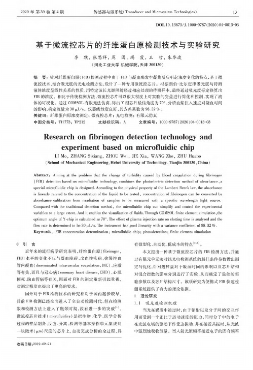
2020年第39卷第4期传感器与微系统(Transducer and Microsystem Technologies)13DOI:10.13873/J.1000-9787(2020)04-0013-03基于微流控芯片的纤维蛋白原检测技术与实验研究李默,张思祥,周围,竭霞,王哲,朱华波(河北工业大学机械学院,天津300130)摘要:针对纤维蛋白原(FIB)检测过程中由于FIB与凝血酶发生凝集反应引起浊度变化的特点,基于微流控技术,结合吸光度的光电检测方法,设计了一种专用微流控芯片。
根据朗伯-比尔定律吸光度与待测液体浓度呈线性关系的性质,用特定波长光源照射经过相应处理的待测样本,最终通过吸光度标定换算出FIB的浓度。
相比于传统检测方法,微流控芯片可以很大程度上对实验的变量进行简化和控制,实现了流体的可视化。
通过COMSOL有限元法仿真,得出Y型芯片最佳角度为70。
,分析血浆注入速度对凝血时间的影响,确定流量为30|xiy So仪器线性度良好,其方差系数为98.32%。
关键词:纤维蛋白原浓度测定;微流控芯片;光电检测;有限元仿真中图分类号:TH773;TP212文献标识码:A文章编号:1000-9787(2020)04-0013-03 Research on fibrinogen detection technology andexperiment based on microfluidic chipLT Mo,ZHANG Sixiang,ZHOU Wei,JIE Xia,WANG Zhe,ZHU Huabo(School of Mechanical Engineering,Hebei University of Technology,Tianjin300130,China)Abstract:Aiming at the problem that the change of turbidity caused by blood coagulation during fibrinogen(FIB)detection based on microfluidic technology,combines the photoelectric detection method of absorbance,aspecial microfluidic chip is designed.According to the physical property of the Lambert Beers law,the absorbanceis linearly related to the concentration of the liquid to be tested,concentration of fibrinogen can be converted byabsorbance calibration from irradiation of samples to be measured with a specific wavelength light source・Compared with the traditional detection method,the microfluidic chip can simplify and control the experimentalvariables to a large extent.And it enables the visualization of fluids.Phrough COMSOL finite element simulation,theoptimum angle of Y-chip is calculated as70°.The effect of plasma injection rate on clotting time is analyzed and theflow rate is determined to be30(jl L/s.The instrument has good linearity with a varianee coefficient of98.32%.Keywords:FIB concentration determinalion;microfluidic chip;photodeleclion;finite element simulation0引言近年来的流行病学研究表明,纤维蛋白原(fibrinogen, FIB)水平的变化不仅与凝血障碍、出血性疾病、弥漫性血管内凝血(disseminated intravascular coagulation,DIC)、应激等有关,而且与冠心病(conmary heart disease,CHD)、心肌梗死、脑血管病等有关,因而对FIB的测定重新引起重视,对测定精度也提出了更高的要求。
Xona microfluidics llc神经元突触轴突连接微流体培养板
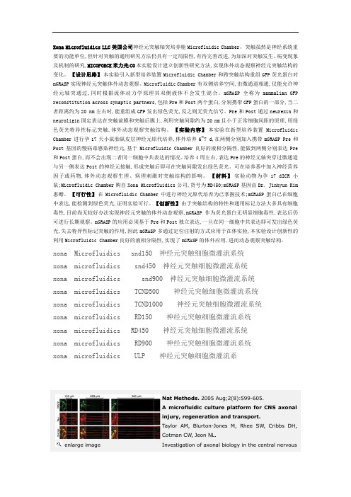
Xona Microfluidics LLC美国公司神经元突触轴突培养舱Microfluidic Chamber,突触虽然是神经系统重要的功能单位,但针对突触的通用研究方法仍具有一定局限性,有待完善改进,为加深对突触发生、病变现象及机制的研究,MICOFORCE米力光CO本实验设计建立创新性研究方法,实现体外动态观察神经元突触结构的变化。
【设计思路】本实验引入新型培养装置Microfluidic Chamber和跨突触结构重组GFP荧光蛋白对mGRASP实现神经元突触体外动态观察。
Microfluidic Chamber有双侧培养空间,由微通道相通,仅能允许神经元轴突通过,同时根据流体动力学原理其双侧液体不会发生混合。
mGRASP全称为mammalian GFP reconstitution across synaptic partners,包括Pre和Post两个蛋白,分别携带GFP蛋白的一部分,当二者距离约为20 nm左右时,能重组成GFP发出绿色荧光,反之则无荧光信号。
Pre和Post通过neurexin和neuroligin固定表达在突触前膜和突触后膜上,利用突触间隙约为20 nm且小于正常细胞间距的原理,用绿色荧光特异性标记突触,体外动态观察突触结构。
【实验内容】本实验在新型培养装置Microfluidic Chamber进行孕17天小鼠胎鼠皮层神经元原代培养,体外培养6~7 d,在两侧分别加入携带mGRASP Pre和Post基因的慢病毒感染神经元,基于Microfluidic Chamber良好的液相分隔性,能做到两侧分别表达Pre 和Post蛋白,而不会出现二者同一细胞中共表达的情况。
培养4周左右,表达Pre的神经元轴突穿过微通道与另一侧表达Post的神经元接触,形成突触后即可在突触间隙发出绿色荧光。
可在培养基中加入神经营养因子或药物,体外动态观察生理、病理刺激对突触结构的影响。
- 1、下载文档前请自行甄别文档内容的完整性,平台不提供额外的编辑、内容补充、找答案等附加服务。
- 2、"仅部分预览"的文档,不可在线预览部分如存在完整性等问题,可反馈申请退款(可完整预览的文档不适用该条件!)。
- 3、如文档侵犯您的权益,请联系客服反馈,我们会尽快为您处理(人工客服工作时间:9:00-18:30)。
M. Matlosz et al. (eds.), Microreaction Technology © Springer-Verlag Berlin Heidelberg 2001
26
a)
Heater resistor Air chamber Flow sensor
Pump Chamber
Valve 2
Piezos Pyrex Silicon
Figure 3: Peristaltic micropump. From left to right: top view and cross section showing the basic design, and photograph of a realized pump. In the cross section the pump membranes are shown in the activated upward position.
Microfluidics and Microtechnology for Microreactor Systems
N.R. Tas, R.E. Oosterbroek, T.T. Veenstra, M. Elwenspoek and A. van den Berg MESA+ Research Institute, University of Twente, P.O. Box 217,7500 AE Enschede, The Netherlands. Fax: +31-53-4893343. E-mail: A.vandenberg@el.utwente.nl
Wafer Bonding Technology
To understand the conditions for fusion bonding, a fundamental study has been done into the bondability of wafers as a function of surface roughness, elastic and adhesive properties of the surfaces. The result is a model that predicts bondability with a single parameter, the dimensionless surface adhesion parameter [7]. With the knowledge of the relation between surface roughness and bondability, it is
27
-
.-~
~-.
"4'"
Figure 2: Thin {III} plate after fusion bonding to create a closed channel, magnification of the {Ill} plate, and 3D-structured 4: MFS demonstrator. It consists of two inlets, two flow sensors and two pumps, a mixing unit and a detection unit. The fluidic system is connected to the control electronics which are collected on the lower circuit board [11].
Robust Peristaltic Pump An improved peristaltic piezoelectrically driven micropump has been made using silicon-glass sandwich technology [9). The improvement, compared to previously presented peristaltic micropumps, is that it is self-priming and it can pump any gas bubbles present in the liquid. The design and fabrication are extremely simple: the process is robust and in principle needs only one lithographic step. In order for a pump to be bubble tolerant, this compression ratio should be larger than 0.08. In the design of the peristaltic pump, the compression ratio is chosen to be 0.5. This results in a maximum pressure of 500 mBar. The design of the micropump is shown in fig. 3. It also shows a picture of a realized pump. The membranes are created from a 220± 10 11m thick pyrex wafer, which is anodically bonded to the silicon substrate wafer. In order to have low-dead volume pumping chambers, a selective bonding method has been used, in which the membranes are coated with chromium to prevent bonding locally [10). The pump produces a maximum flow of 9 Ill/min, at a stroke frequency of about 400 Hz [9).
28 possible to obtain selective bonding: In regions with (tailored) increased surface roughness bonding can be prevented [8]. This technique can be used for example to prevent bonding of a bossed type valve seat to the counter surface [8].
1. INTRODUCTION In this paper we outline the evolution of the silicon-based technology for microchemical systems in the MESA Research Institute. There is a tendency toward the handling of smaller volumes, which leads to the development of fully integrated micro-fluidic systems, based mainly on thin film technology. Several examples of microdevices and systems will be discussed. 2. STACKING OF SILICON AND GLASS WAFERS The history of micro-liquid handling systems at Twente University goes back to the eighties, with the development of the piezoelectrically driven micropumps of Smits et al. [1] and van Lintel et al. [2]. Both pumps were based on stacking of glass-silicon-glass wafers, to create closed chambers and channels. An important step in system integration was the development of a micro-liquid dosing system [3], consisting of a pump and a flowsensors (fig. 1), fabricated simultaneously in glass-silicon-glass technology [3]. In order to support this bulk micromachining technology, our micromechanics group investigates etching of silicon, and both anodic and fusion bonding on a more fundamental level. In collaboration with the solid state chemistry group of the University of Nijmegen, physical-chemical theories of anisotropic and isotropic wet-chemical etching of silicon are developed. The results of this project include a simulation tool for anisotropic wet chemical etching [4], as well as an explanation for the formation and stabilization of pyramidal etch hillocks on Si{100} [5]. Another result of the more fundamental look at KOH etching is a design method to create thin {Ill} plates in <100> oriented silicon (fig. 2). Although the processing involves doublesided etching, precision alignment is only required at one side of the wafer [6]