FraqhuUA741中文资料
公会前台接待员菲利斯回想码

公会前台接待员菲利斯回想码一、引言公会前台接待员菲利斯回想码是一种引人注目的概念,它代表了在虚拟世界中的一种独特角色。
作为公会前台接待员,菲利斯在游戏中扮演着重要的角色,负责处理公会成员的问题、协调会议安排等工作。
在这篇文章中,我将从深度和广度的角度对菲利斯回想码进行全面评估,并分享我对这个概念的个人观点和理解。
二、深度评估:菲利斯回想码的含义和作用菲利斯回想码是指公会前台接待员菲利斯回想过去所经历的种种事件和经验。
它可以是一种虚拟世界中的记忆方式,也可以是一种人工智能的工具,用于帮助菲利斯更好地处理公会事务。
1. 虚拟世界中的回想码在虚拟世界中,回想码是一种特殊的技术,它允许菲利斯在游戏中回顾过去发生的事情,包括公会活动、会员关系、任务完成情况等。
通过回想码,菲利斯可以更准确地记忆事实,避免遗忘或错误记忆,从而更好地为公会成员提供服务。
2. 人工智能的应用除了在虚拟世界中使用,菲利斯回想码还可以作为一种人工智能工具应用于现实生活中。
通过对菲利斯过去的活动和经验进行记录和分析,人工智能系统可以为菲利斯提供更准确的建议和决策支持。
当公会成员提出问题或寻求建议时,菲利斯回想码可以快速提供相关信息,帮助菲利斯做出更好的回答和建议。
三、广度评估:菲利斯回想码的应用领域菲利斯回想码不仅在游戏中有着重要作用,也可以在现实生活中有广泛的应用。
1. 游戏中的应用作为公会前台接待员,菲利斯回想码可以帮助菲利斯更好地管理公会事务。
通过回想过去的任务和活动,菲利斯可以更好地了解公会成员的特点和需求,提供个性化的服务和咨询。
回想码还可以对公会的发展进行分析和预测,为公会的决策提供数据支持。
2. 现实中的应用除了在游戏中的应用,菲利斯回想码在现实生活中也有潜在的应用领域。
在客户服务行业中,回想码可以帮助前台接待员更好地记忆客户需求和历史记录,提供更个性化和高效的服务。
回想码还可以用于培训和教育领域,帮助学生或员工回顾学习或工作过程中的重要内容和经验。
UA741中文资料
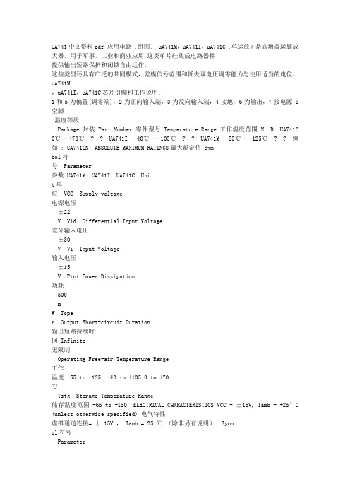
UA741中文资料pdf 应用电路(组图) uA741M,uA741I,uA741C(单运放)是高增益运算放大器,用于军事,工业和商业应用.这类单片硅集成电路器件提供输出短路保护和闭锁自由运作。
这些类型还具有广泛的共同模式,差模信号范围和低失调电压调零能力与使用适当的电位。
uA741M,uA741I,uA741C芯片引脚和工作说明:1和5为偏置(调零端),2为正向输入端,3为反向输入端,4接地,6为输出,7接电源 8空脚温度等级Package 封装 Part Number零件型号 Temperature Range 工作温度范围 N D UA741C 0℃ - +70℃ ? ? UA741I -40℃ - +105℃ ? ? UA741M -55℃ - +125℃ ? ? 例如 : UA741CN ABSOLUTE MAXIMUM RATINGS最大额定值 Symbol符号 Parameter参数 UA741M UA741I UA741C Unit单位 VCC Supply voltage电源电压±22V Vid Differential Input Voltage差分输入电压±30V Vi Input Voltage输入电压±15V Ptot Power Dissipation功耗500mW Toper Output Short-circuit Duration输出短路持续时间 Infinite无限制Operating Free-air Temperature Range工作温度 -55 to +125 -40 to +105 0 to +70℃Tstg Storage Temperature Range储存温度范围 -65 to +150 ELECTRICAL CHARACTERISTICS VCC = ±15V, Tamb = +25°C (unless otherwise specified) 电气特性虚拟通道连接= ± 15V , Tamb = 25 ℃(除非另有说明) Symbol符号Parameter参数最小. 典型. 最大. Unitd单位 Vio Input Offset Voltage (Rs ≤ 10K?)输入失调电压 - mV Tamb = +25℃ - 1 5 Tmin ≤ Tamb ≤ Tmax - - 6 Iio Input Offset Current 输入失调电流 nA Tamb = +25℃ - 2 30 Tmin ≤ Tamb ≤ Tmax - - 70 Iib Input Bias Current 输入偏置电流 nA Tamb = +25℃ - 10 100 Tmin ≤ Tamb ≤ Tmax - - 200 Avd Large Signal Voltage Gain (Vo=±10V, RL=2K?) 大信号电压增益 V/mV Tamb = +25℃ 50 200 - Tmin ≤ Tamb ≤ Tmax 25 -SVR Supply Voltage Rejection Ratio (Rs ≤ 10K?)电源电压抑制比 dB Tamb = +25℃ 77 90 - Tmin ≤ Tamb ≤ Tmax 77 - - ICC Supply Current, no load 电源电流(空载) mA Tamb = +25℃ - 1.7 2.8 Tmin ≤ Tamb ≤ Tmax - - 3.3 Vicm Input Common Mode Voltage Range 输入共模电压范围 V Tamb = +25℃±12 - - Tmin ≤ Tamb ≤ Tmax ±12 - - CMR Common Mode Rejection Ratio (RS ≤ 10K?)共模抑制比 dB Tamb = +25℃ 70 90 - Tmin ≤ Tamb ≤ Tmax 70 - - IOS Output short Circuit Current输出短路电流 10 25 40 mA ±Vopp Output Voltage Swing输出电压摆幅 Tamb=+25℃ RL=10K? 12 14 - V RL=2K? 10 13 - Tmin≤Tamb ≤Tmax RL=10K? 12 - - RL=2K? 10 - - SR Slew Rate Vi=±10V,RL=2K?,CL=100pF,unity Gain 转换率单位增益 0.25 0.5 - V/μs tr Rise Time Vi = ±20mV, RL =2K?,CL = 100pF, u- 0.3 - μs nity Gain 上升时间单位增益Kov Overshoot Vi=20mV,RL=2K?,CL=100pF,unity Gain 超虚拟单位增益 - 5 - % Ri Input Resistance输入阻抗 0.3 2 - M? GBP Gain Bandwith Product Vi = 10mV, RL =2K?,CL= 100pF, f =100kHz 带宽增益 0.7 1 - MHz THD Total Harmonic Distortion f = 1kHz, Av = 20dB, RL=2K?,Vo=2Vpp, CL=100pF,Tamb=+25℃总谐波失真 - 0.06 - % en Equivalent Input Noise Voltage f=1kHz,Rs=100?等效输入噪声电压 - 23 - nV√Hz ¢m Phase Margin 相位裕度 - 50 - Degrees UA741/ LM741应用电路:图 6 12V的电池监视器图7 低功耗放大器图8 741驱动三极管的5瓦功率放大器图9 自动感光电路图。
冰橙子简介

4、保护功能讲解:
■智能刷包:按照你设置的时间智能刷包,避免卡药;
■HP≤:少于你设置的血量开始喝药;
■药品名称:可自己设置喝药的名字;
■本位摘自:冰橙子
■间隔:喝药速度;
■MP≤:少于你设置的魔法量开始喝药;
■自动解包:调节解包时间;
■ESC回城:选择好回城物品,按ESC可强制回城;
■骑马魔法:即可一步三格加移动魔法;
■保存配置:输入名字即可保存,下次选择该名字即可还原你的设置。
2、 战士功能讲解:
■攻击不卡:使出刀动作流畅,优化出刀速度;
■强力攻击:使你的出刀速度更加快;
■隐藏交易:屏蔽交易框;
■隐藏挑战:屏蔽挑战框;
■自动刷包:按照你设置的时间循环自动刷包;
■解包:“药品包”“药品”少于你设置的药品数量开始解包;
■道士治愈:少于你设置的血量自动治愈术;
■HP小退:少于你这是的血量自动小退;
■HP回城:少于你设置的血量自动使用你设置的回城物品;
■麻痹回城:被麻痹自动使用你设置的回城物品;
■复活回城:复活后自动使用你设置的回城物品;
模糊匹配自动捡取跟飞取装备,亮点所在-一键传送,鼠标点哪里就飞哪里。无需坐标飞机般的感觉!
以下功能用过冰橙子的应该都知道,第一次用辅助可以看看。增加对七剑的了解!
1、加速功能讲解:
■攻击提速:优化出刀动作,提高攻击速度;
■魔法提速:优化魔法动作,提高魔法速度;
■移动提速:优化移动动作,提高移动速度;
详细解释下本辅助亮点所在。以及独家功能:
战士锁血自动近身烈火-76版本带4级烈火服功能狠实用!
HFL DOTA1v1-5v5比赛规则

Dota一、基本信息比赛线路:电信\网通。
比赛地图:DotA Allstars v6.66B比赛模式:5V5游戏版本:魔兽争霸3之冰封王座(版本:TFT1.24)比赛地点:浩方平台DOTA积分房比赛模式:-cm 1 (近位先ban/pick)二、参赛、签到规则(1)玩家填写完报名资料后系统自动生成到对阵表中,玩家根据对阵表分组在开赛前加入官方公布的相对应比赛群中;(2)玩家进群后,依照群裁判要求修改名片,否则一律按弃权处理。
另外,玩家需按照群公告的要求和规定准时签到;(3)通常签到时间15分钟内玩家还没有正常签到,将一律视作弃权处理;(4)每一轮选手都将按照裁判在群公告的要求准时签到,否则一律视作弃权处理。
三、战队、选手规则(1)严禁在比赛过程中以任何理由辱骂对手,辱骂裁判。
一旦发生辱骂行为,当值裁判有权将辱骂他人者所在的战队直接判负。
(2)除队长之外,选手不允许在比赛中使用公聊。
(3)如果选手有其他不当的行为,视情节严重,由裁判做出处罚。
(4)每支队伍允许报名最少5名,由队长统一负责联系比赛。
(5)比赛过程中不允许私自更换队员,一旦战队队员名单确定将不能更改。
(6)队长和联络官即为队伍的联系人,队长的决定代表整只队伍,有任何问题裁判也只会与队长协调,其他队员与裁判之间进行的任何商议均被视为无效。
四、比赛规则1.物品共享- 允许共享通用物品,但禁止卖出。
- 禁止交易圣剑,禁止故意自杀让队友拾取圣剑。
- 出现掉线情况,可以使用掉线者的英雄继续进行比赛。
任何情况下都不允许其他人使用或出售掉线者的物品,但允许由掉线者卖出(team sell)。
2.比赛限制- 允许杀死队友- 禁止利用游戏中的漏洞及bug等导致游戏出错- 禁止恶意停滞小兵。
允许短时间在小兵的移动路线上控制其前进速度- 禁止滥用暂停。
在一般情况下,每队队长可以各暂停游戏1次,每次最长2分钟- 禁止BD高地建筑。
只允许从有小兵的战线进入对方高地攻击建筑,允许当己方的兵全部死光时仍继续攻击敌人基地里的任意建筑物,一旦进攻方退下防守方高地则必须等待下一波兵的到达基地后方可再次对敌方建筑物进行攻击- 禁止一切作弊。
GIS 500 Professional 说明书

2 |English...................................................Page5Español................................................Página23Português do Brasil.....................................Página37中文.......................................................页48繁體中文..................................................頁59한국어...............................................페이지68ไทย......................................................หน้า78Bahasa Indonesia.....................................Halaman91Tiếng Việt...............................................Trang1021 609 92A 5H0 | (16.12.2019)Bosch Power Tools| 3Bosch Power Tools1 609 92A 5H0 | (16.12.2019)4 |°C(h)(i)(e)(d)(f)(g)1 609 92A 5H0 | (16.12.2019)Bosch Power ToolsEnglish | 5 EnglishSafety instructionsAll instructions must be read and observed in order for the meas-uring tool to function safely. The safeguards integrated into themeasuring tool may be compromised if the measuring tool is notused in accordance with these instructions. Never make warningsigns on the measuring tool unrecognisable. SAVE THESE IN-STRUCTIONS FOR FUTURE REFERENCE AND INCLUDE THEM WITH THE MEASUR-ING TOOL WHEN TRANSFERRING IT TO A THIRD PARTY.u Warning! If operating or adjustment devices other than those specified here are used or other procedures are carried out, this can lead to dangerous exposure to radiation.u The measuring tool is delivered with a warning label (marked in the illustrationof the measuring tool on the graphics page).uyour head away from the beam.u Do not make any modifications to the laser equipment.u Do not use the laser goggles as protective goggles. The laser goggles make the laser beam easier to see; they do not protect you against laser radiation.u Do not use the laser goggles as sunglasses or while driving. The laser goggles do not provide full UV protection and impair your ability to see colours.Bosch Power Tools 1 609 92A 5H0 | (16.12.2019)6 | Englishu Have the measuring tool serviced only by a qualified specialist using only ori-ginal replacement parts. This will ensure that the safety of the measuring tool is maintained.u Do not let children use the laser measuring tool unsupervised. They could acci-dentally dazzle someone.u Do not use the measuring tool in explosive atmospheres which contain flam-mable liquids, gases or dust. Sparks may be produced inside the measuring tool, which can ignite dust or fumes.u The measuring tool may not be 100% accurate for technological reasons. Envir-onmental factors (e.g. dust or steam in the area being measured), temperature fluctu-ations (e.g. from fan heater) as well as the nature and condition of the surfaces being measured (e.g. highly reflective or transparent materials) can distort measurement readings.u Protect the measuring tool, particularly the area around the infrared lens and laser, from moisture and snow. The reception lens could fog up and distort the measurements. Incorrect settings on the tool and other atmospheric influences maymake the measurements inaccurate. Otherwise, object temperatures could be shown to be hotter or colder than they are, which may present a danger if touched.u Temperature measurements will only be correct if the emissivity setting matches the emissivity of the object. Otherwise, object temperatures could be shown to be hotter or colder than they are, which may present a danger if touched.u Take the batteries out of the measuring tool when it is being stored or transpor-ted. Persons are at risk of being blinded if the on/off switch is unintentionally pressed.Product Description and SpecificationsPlease observe the illustrations at the beginning of this operating manual.Intended UseThe measuring tool is intended for contactless measurement of surface temperature. The measuring tool must not be used for temperature measurement on persons and an-imals or for other medical purposes.The measuring tool is not suitable for surface temperature measurement of gases or li-quids.The measuring tool is not intended for temperature measurement of food.The measuring tool is suitable for indoor use.1 609 92A 5H0 | (16.12.2019)Bosch Power ToolsEnglish | 7Product FeaturesThe numbering of the product features shown refers to the illustration of the measuring tool on the graphic page.Display elementsTechnical dataBosch Power Tools 1 609 92A 5H0 | (16.12.2019)8 | English1 609 92A 5H0 | (16.12.2019)Bosch Power ToolsEnglish | 9At an ambient temperature T of between –5 °C and 21 °C the measuring accuracy varies by±0.1×|T–21| °C for surface temperatures below 100 °C and±0.1×|T–21| % for surface temperatures above 100 °C.At an ambient temperature T of between 25 °C and 50 °C the measuring accuracy varies by±0.1×|T–25| °C for surface temperatures below 100 °C and±0.1×|T–25| % for surface temperatures above 100 °C.B)At a measuring distance of 0.1–0.3 m from the surfaceC)At a measuring distance of 0.75–1.25 m from the surfaceD)Refers to infrared measurement, see figure:E)Values in accordance with the Association of German Engineers' VDI/VDE 3511 part 4.3 stand-ard (publication date July 2005); applies for 90 % of the measuring signal.In all areas beyond the values detailed in the technical data, deviations are possible in measure-ment readings.F)Only non-conductive deposits occur, whereby occasional temporary conductivity caused bycondensation is expected.AssemblyInserting/changing the batteriesIt is recommended that you use alkaline manganese batteries to operate the measuring tool.To open the battery compartment cover (4), press the locking mechanism (5) and lift open the battery compartment cover. Insert the batteries. When inserting the batteries, ensure the polarity is correct according to the representation on the inside of the battery compartment cover.The battery indicator (a) shows the batteries' state of charge:Bosch Power Tools 1 609 92A 5H0 | (16.12.2019)10 | Englishreplaced.Always replace all the batteries at the same time. Only use batteries from the same man-ufacturer and which have the same capacity.u Take the batteries out of the measuring tool when you are not using it for a pro-longed period of time. The batteries can corrode and self-discharge during pro-longed storage.OperationStarting Operationu Protect the measuring tool from moisture and direct sunlight.u Do not expose the measuring tool to any extreme temperatures or variations in temperature. For example, do not leave it in a car for extended periods of time. In case of large variations in temperature, allow the measuring tool to adjust to the ambi-ent temperature before putting it into operation. The precision of the measuring tool may be compromised if exposed to extreme temperatures or variations in temperat-ure.u Make sure that the measuring tool is correctly acclimatised. In case of large vari-ations in temperature, acclimatisation can take up to 30 minutes. This may be the case, for example, if you first perform a measurement in the cool cellar and then go up to the warm attic.u Avoid hard knocks to the measuring tool or dropping it. After severe external influ-ences and in the event of abnormalities in the functionality, you should have the measuring tool checked by an authorised Bosch after-sales service agent.u Do not close or cover the reception lens (2) or the laser outlet aperture (1).1 609 92A 5H0 | (16.12.2019)Bosch Power ToolsEnglish | 11Switching on/offThe following options are available for switching on the measuring tool:–Switch on the measuring tool using the on/off button (9). The measuring tool will be ready to use again following a brief start-up sequence. No measurement is initiated at this stage and the laser is still switched off.–Switch on the measuring tool using the measuring button (3). After briefly pressing the measuring button (3), the measuring tool will be ready to take measurements following a brief start-up sequence. If you press and hold the measuring button (3) for more than three seconds, the laser will be switched on after the start-up sequence and the measuring tool will immediately begin measuring.u Never leave the measuring tool unattended when switched on, and ensure the measuring tool is switched off after use. Others may be dazzled by the laser beam. u Do not direct the laser beam at persons or animals and do not stare into the laser beam yourself (even from a distance).To switch off the measuring tool, press the on/off button (9).If no button on the measuring tool is pressed for approx. 1 minutes, the measuring tool will automatically switch off to preserve battery life.Measurement preparationsAdjusting the emissivityTo determine the surface temperature, the tool performs a contactless measurement of the natural infrared thermal radiation emitted by the object at which the tool is aimed. For optimum measuring results, the emissivity setting (see "Emissivity", page 14) on the measuring tool must be checked before every measurement and adapted to the ob-ject being measured if necessary.When the measuring tool is switched on for the first time, the high emissivity setting is activated by default. If the emissivity is changed, all the measured values will be erased. The emissivity setting remains saved when the measuring tool is switched off.You can select from three different emissivity settings on the measuring tool. The follow-ing overview shows commonly used materials of a similar emissivity for each emissivity setting; note that these are examples and not an exhaustive list. Because the emissivity of a material is dependent on a variety of factors and is therefore variable, the details in the following overview serve only as guide values.Bosch Power Tools 1 609 92A 5H0 | (16.12.2019)12 | EnglishThe following emissivity gradings are used:–High emissivity grading: Approx. 0.95–Medium emissivity grading: Approx. 0.85–Low emissivity grading: Approx. 0.75To change the emissivity setting, press the button Mode (8) repeatedly until the emissiv-ity indicator (c) shows the required emissivity for the next measurement.u Temperature measurements will only be correct if the emissivity setting matches the emissivity of the object. Otherwise, object temperatures could be shown to be hotter or colder than they are, which may present a danger if touched. Measuring surfaceThe infrared radiation of the measuring surface is determined during the contactless measurement of the surface temperature.The laser point marks the approximate centre of the measuring surface. For an optimum measurement reading, position the measuring tool so that the laser beam meets the measuring surface perpendicularly to this point.u Do not direct the laser beam at persons or animals and do not stare into the laser beam yourself (even from a distance).Increasing the distance between the measuring tool and the object being measured in-creases the size of the measuring surface. At a distance of 1 m, the measuring surface is approx. 8.3 cm in size if the laser beam is perpendicular to a flat measuring surface.1 609 92A 5H0 | (16.12.2019)Bosch Power ToolsEnglish | 13 At a surface temperature of −10 °C to +500 °C, the optimum measuring distance is between 0.75 m and 1.25 m. Below −10 °C, the optimum measuring distance is between 10 cm and 30 cm.The displayed reading is the average value of all temperatures measured within the measuring surface.u Stand back from very hot objects. There is a risk of burns.u Do not hold the measuring tool directly against hot surfaces. The heat can damage the measuring tool.Information about the measuring conditionsHighly reflective or glossy surfaces (e.g. glossy tiles, stainless steel fronts or cooking pots) can affect the surface temperature measurement. If necessary, mask the area to be measured with a dark, matt adhesive tape that conducts heat well. Allow the tape to ac-climatise briefly on the surface.Measuring through transparent materials (e.g. glass or transparent plastics) is funda-mentally not possible.Consequently, the more suitable and stable the measuring conditions are, the more ac-curate and reliable the measurement readings are.Infrared temperature measurement is impaired by smoke, steam or dusty air.It is therefore important to ventilate the room prior to measuring, especially when the air is contaminated or steamy. For example, do not perform measurements in a bathroom immediately after the shower has been used.Once ventilated, allow the room to reacclimatise a while until it returns to the usual tem-perature.Measuring functionsIndividual measurementsBriefly pressing the measuring button (3) once switches the laser on and actuates a single measurement.The measuring process can take up to half a second and is indicated by the SCAN (h) in-dicator lighting up. Once the measurement has been completed, the laser switches off automatically, the indicator SCAN disappears and both the most recent measurement reading and the reading before it are shown on the display.Continuous measurementFor continuous measurements, press and hold the measuring button (3). The laser re-mains switched on and the indicator SCAN appears in the display. Using slow move-ments, aim the laser at each of the surfaces to be measured, one by one.Bosch Power Tools 1 609 92A 5H0 | (16.12.2019)14 | EnglishThe indicator on the display is continually updated. As soon as you let go of the measur-ing button (3), the measurement is stopped, the indicator SCAN disappears and the laser is switched off.The most recent measurement reading and the reading before it are shown on the dis-play.Errors – causes and corrective measuresMeasuring tool not acclimatisedThe measuring tool has been subjected to extreme fluctuations in temperature and did not have sufficient time to adjust.Ambient temperature outside the operating temperature rangeThe ambient temperature is too high or too low for the measuring tool to operate. Surface temperature outside the measuring rangeThe indicator flashes if the surface temperature of the object being measured in the measuring area is too high (above 500 °C, see indicator (g)) or too low (below −30 °C,see indicator (f)). The temperature of this object cannot be measured. Aim the laser at another object and start a new measurement.Internal errorIf the measuring tool has an internal fault, Err is shown on the display and the (i) sym-bol flashes. To reset the software, remove the batteries, wait a few seconds and then re-insert the batteries.If the error persists, have the measuring tool checked by a Bosch customer service agent. Do not open the measuring tool yourself.Glossary of termsEmissivityThe emissivity of an object depends on the material and the structure of its surface. It in-dicates whether a particular object emits a high or low level of infrared thermal radiation (in comparison to other objects of the same temperature).1 609 92A 5H0 | (16.12.2019)Bosch Power ToolsEnglish | 15 Maintenance and ServiceMaintenance and Cleaningu Check the measuring tool before each use. If the measuring tool is visibly damaged or parts have become loose inside the measuring tool, safe function can no longer be ensured.Only store and transport the measuring tool in a suitable container, such as the original packaging. Do not affix any stickers near to the sensor on the measuring tool.Always keep the measuring tool clean and dry to ensure optimum, safe operation. Never immerse the measuring tool in water or other liquids.Wipe off any dirt using a dry, soft cloth. Do not use any detergents or solvents.When cleaning the measuring tool, ensure that no liquids enter the tool.Clean the reception lens (2) and laser outlet aperture (1) very carefully:Ensure that there is no lint on the reception lens or the laser outlet aperture. Do not at-tempt to remove dirt from the reception lens using pointed objects, and do not wipe overthe reception lens (risk of scratching). If necessary, you can carefully blow away dirt us-ing oil-free compressed air.If repairs are required, send in the measuring tool in its original packaging.After-Sales Service and Application ServiceOur after-sales service responds to your questions concerning maintenance and repair of your product as well as spare parts. You can find explosion drawings and information on spare parts at: The Bosch product use advice team will be happy to help you with any questions about our products and their accessories.In all correspondence and spare parts orders, please always include the 10‑digit article number given on the nameplate of the product.CambodiaRobert Bosch (Cambodia) Co., LtdUnit 8BC, GT Tower, 08th Floor, Street 169,Czechoslovakia Blvd, Sangkat Veal VongKhan 7 Makara, Phnom PenhVAT TIN: 100 169 511Tel.: +855 23 900 685Tel.: +855 23 900 660.khBosch Power Tools 1 609 92A 5H0 | (16.12.2019)16 | EnglishPeople’s Republic of ChinaChina MainlandBosch Power Tool (China) Co. Ltd.Bosch Service Center567, Bin Kang RoadBin Kang DistrictHangzhou, Zhejiang ProvinceChina 310052Tel.: (0571) 8887 5566 / 5588Fax: (0571) 8887 6688 x 5566# / 5588#E-Mail:***************.comHK and Macau Special Administrative RegionsRobert Bosch Co. Ltd.21st Floor, 625 King’s RoadNorth Point, Hong KongCustomer Service Hotline: +852 2101 0235Fax: +852 2590 9762E-Mail:*************.comIndiaBosch Service Center69, Habibullah Road, (Next to PSBB School), T. NagarChennai–600077Phone: (044) 64561816Bosch Service Center18, Community CenterPhase 1, MayapuriNew Delhi–110064Phone: (011) 43166190IndonesiaPT Robert BoschPalma Tower 10th FloorJalan RA Kartini II-S Kaveling 6Pondok Pinang, Kebayoran LamaJakarta Selatan 12310Tel.: (21) 3005-5800www.bosch-pt.co.id1 609 92A 5H0 | (16.12.2019)Bosch Power ToolsEnglish | 17 MalaysiaRobert Bosch Sdn. Bhd.(220975-V) PT/SMYNo. 8A, Jalan 13/646200 Petaling JayaSelangorTel.: (03) 79663194Toll-Free: 1800 880188Fax: (03) 79583838E-Mail:**********************.com.myPakistanRobert Bosch Middle East FZE – Pakistan Liaison Office2nd Floor Plaza # 10, CCA Block, DHA Phase 5Lahore, 54810Phone: +92(303)4444311Email:*********************PhilippinesRobert Bosch, Inc.28th Floor Fort Legend Towers,3rd Avenue corner 31st Street,Fort Bonifacio, Global City,1634 Taguig CityTel.: (632) 8703871Fax: (632) 8703870.phSingaporePowerwell Service Centre Ptd LtdBosch Authorised Service Centre (Power Tools)4012 Ang Mo Kio Ave 10, #01-02 TECHplaceSingapore 569628Tel.: 6452 1770Fax: 6452 1760E-Mail:*******************.sgThailandRobert Bosch Ltd.FYI Center Tower 1, 5th Floor,Bosch Power Tools 1 609 92A 5H0 | (16.12.2019)18 | English2525 Rama IV Road, Klongtoei,Bangkok 10110Tel.: 02 0128888Fax: 02 0645802www.bosch.co.thBosch Service – Training CentreLa Salle Tower Ground Floor Unit No.210/11 La Salle Moo 16Srinakharin RoadBangkaew, Bang PleeSamutprakarn 10540Tel.: 02 7587555Fax: 02 7587525VietnamBranch of Bosch Vietnam Co., Ltd in HCMC14th floor, Deutsches Haus, 33 Le DuanBen Nghe Ward, District 1, Ho Chi Minh CityTel.: (028) 6258 3690Fax: (028) 6258 3692 - 6258 3694Hotline: (028) 6250 8555Email:**************************.com.vnBahrainEA Juffali and Brothers for Technical Equipment Company.Kingdom of Bahrain, Al Aker - Block 0624 - Road 2403 - Building 0055DPhone: +97317704537Fax: +973177045257Email:*****************.saEgyptRBEG-LLC22 Kamal Eldin HusseinSheraton Heliopolis11799 CairoE-mail:******************************.comIranRobert Bosch Iran3rd Floor, No 3, Maadiran BuildingAftab St., Khodami St., Vanak Sq.1 609 92A 5H0 | (16.12.2019)Bosch Power ToolsEnglish | 19 Tehran 1994834571Phone: +9821- 86092057IraqSahba Technology GroupAl Muthana airport roadBaghdadPhone Bagdad: +964 (0) 7 901 930366Phone Dubai: +971 (0) 4 422 1898Email:**************************JordanRoots Arabia – JordanAl-Hurriyah Street, Al-MuqabaleinAmman 11623, JordanP.O. Box: 110068Tel. : +962 6 4398990E-mail:*********************KuwaitShuwaikh Industrial Area, Block 1, Plot 16, Street 3rdP.O. Box 164 – Safat 13002Phone: +965 - 2496 88 88Fax: +965 - 2481 08 79E-mail:***********************LebanonTehini Hana & Co. S.A.R.L.P.O. Box 90-449Jdeideh 1202 2040Dora-BeirutPhone: +9611255211Email:**************************LibyaEl Naser for Workshop ToolsSwanee Road, Alfalah AreaTripoliPhone: +218 21 4811184OmanMalatan Trading & Contracting LLCP.O. Box 131, Ruwi, MuscatBosch Power Tools 1 609 92A 5H0 | (16.12.2019)20 | EnglishPostal Code: 112, Sultanate of OmanPhone: +968 2479 4035/4089/4901Mob: +968-91315465Fax: +968 2479 4058E-Mail:***********************QatarInternational Construction Solutions W L LP. O. Box 51, DohaPhone: +974 40065458Fax: +974 4453 8585Email:***************Saudi ArabiaJuffali Technical Equipment Co. (JTECO)P.O.Box: 1049 – Jeddah 21431 – KSAJeddah: 00966 (0) 12 692 0770 – Ext 433Riyadh: 00966 (0) 11 409 3976 – Ext-30/34/39Dammam: 00966 (0) 13 833 9565E-mail:****************.saSyriaDallal Establishment for Power ToolsDamascus. Baramkeh street - Ibn Amer street,Phone: +963112241006 or 009631122414009Mobile: 00963991141005Email:***********************United Arab EmiratesCentral Motors & Equipment,P.O. Box 26255, DubaiDubai: 00971 (0) 4 3090920/3090930Abu Dhabi: 00971 (0) 2 4017745Sharjah: 00971 (0) 6 5932777Al Ain: 00971 (0) 3 7157419E-Mail:********************************YemenAbu Alrejal Trading CorporationP.O. Box : 17024 , Zubeiry St.Sana'a, YemenTel: +967-1-20 20 101 609 92A 5H0 | (16.12.2019)Bosch Power ToolsEnglish | 21 Fax: +967-1-47 19 17E-mail:*************************/********************EthiopiaForever plcKebele 2,754, BP 4806,Addis AbabaPhone: +251 111 560 600Email:**********************GhanaRobert Bosch Ghana Limited21 Kofi Annan Road Airport Residential Area AccraTel. +233 (0)3027 94616KenyaRobert Bosch East Africa LtdMpaka Road P.O. Box 85600606 NairobiNigeriaRobert Bosch Nigeria Ltd.52–54 Isaac John Street P.O. BoxGRA Ikeja – LagosTanzaniaDiesel & Autoelectric Service Ltd.117 Nyerere Rd., P.O. Box 70839Vingunguti 12109, Dar Es SalaamPhone: +255 222 861 793/794Australia, New Zealand and Pacific IslandsRobert Bosch Australia Pty. Ltd.Power ToolsLocked Bag 66Clayton South VIC 3169Customer Contact CenterInside Australia:Phone: (01300) 307044Fax: (01300) 307045Inside New Zealand:Phone: (0800) 543353Fax: (0800) 428570Bosch Power Tools 1 609 92A 5H0 | (16.12.2019)22 | EnglishOutside AU and NZ:Phone: +61 3 95415555.auRepublic of South AfricaCustomer serviceHotline: (011) 6519600Gauteng – BSC Service Centre35 Roper Street, New CentreJohannesburgTel.: (011) 4939375Fax: (011) 4930126E-Mail:****************.zaKZN – BSC Service CentreUnit E, Almar Centre143 Crompton StreetPinetownTel.: (031) 7012120Fax: (031) 7012446E-Mail:****************.comWestern Cape – BSC Service CentreDemocracy Way, Prosperity ParkMilnertonTel.: (021) 5512577Fax: (021) 5513223E-Mail:**********.zaBosch HeadquartersMidrand, GautengTel.: (011) 6519600Fax: (011) 6519880E-Mail:********************.comArmenia, Azerbaijan, GeorgiaRobert Bosch Ltd.David Agmashenebeli ave. 610102 Tbilisi, GeorgiaTel. +9953225100731 609 92A 5H0 | (16.12.2019)Bosch Power ToolsEspañol | 23 Kyrgyzstan, Mongolia, Tajikistan, Turkmenistan, UzbekistanTOO “Robert Bosch” Power Tools, After Sales ServiceMuratbaev Ave., 180050012, Almaty, KazakhstanServiceEmail:***********************Official Website: , IsraelLedico Ltd.31 Lazrov StreetP.O. Box 6018 Rishon Le Ziyon******************DisposalMeasuring tools, accessories and packaging should be recycled in an environmentallyEspañolIndicaciones de seguridadLeer y observar todas las instrucciones, para trabajar sin peligroy riesgo con el aparato de medición. Si el aparato de medición nose utiliza según las presentes instrucciones, pueden menoscabar-se las medidas de seguridad integradas en el aparato de medi-ción. Jamás desvirtúe las señales de advertencia del aparato de medición. GUARDE BIEN ESTAS INSTRUCCIONES Y ADJUNTELAS EN LA ENTREGA DEL APARATO DE MEDICIÓN.u Precaución – si se utilizan dispositivos de manejo o de ajuste distintos a los espe-cificados en este documento o si se siguen otros procedimientos, esto puede conducir a una peligrosa exposición a la radiación.u El aparato de medición se entrega con un rótulo de advertencia (marcado en la representación del aparato de medición en la página ilustrada con el número). Bosch Power Tools 1 609 92A 5H0 | (16.12.2019)24 | Españolbralo con la etiqueta adhesiva adjunta en su idioma del país antes de la primerauver inmediatamente la cabeza fuera del rayo.u No efectúe modificaciones en el equipamiento del láser.u No utilice las gafas de visualización láser como gafas protectoras. Las gafas de vi-sualización láser sirven para detectar mejor el rayo láser; sin embargo, éstas no prote-gen contra la radiación láser.u No utilice las gafas de visualización láser como gafas de sol o en el tráfico. Las ga-fas de visualización láser no proporcionan protección UV completa y reducen la per-cepción del color.u Sólo deje reparar el aparato de medición por personal técnico calificado y sólo con repuestos originales. Solamente así se mantiene la seguridad del aparato de medición.u No deje que niños utilicen el aparato de medición láser sin vigilancia. Podrían deslumbrar involuntariamente personas.u No trabaje con el aparato de medición en un entorno potencialmente explosivo, en el que se encuentran líquidos, gases o polvos inflamables. El aparato de medi-ción puede producir chispas e inflamar los materiales en polvo o vapores.u Debido a motivos tecnológicos, la herramienta de medición no puede garantizar una seguridad absoluta. Las influencias del medio ambiente (p. ej. polvo o vapor en el margen de medición), las fluctuaciones de temperatura (p. ej. por termoventilador) así como naturaleza y estado de las superficies de medición (p. ej. materiales alta-mente reflectantes o transparentes) pueden falsear los resultados de la medición.u Proteja el aparato de medición, especialmente el área del lente infrarrojo y el lá-ser, ante la humedad y la nieve. El lente receptor podría empañarse y falsear los resultados de medición. Los ajustes incorrectos del aparato así como otros factores1 609 92A 5H0 | (16.12.2019)Bosch Power Tools。
配属中国的部分as号码

出于管理和扩展的目的,因特网可以被分割成许多不同的自治系统(Autonomous System)。
换句话说,因特网是由自治系统汇集而成的。
BGPv4(Border gateway protocol Version 4)——边缘网关协议(定义于RFC1771),是现行因特网的实施标准,就是用来连接自治系统,实现自治系统间的路由选择功能的。
第一章关于AS号码自治系统(Autonomous System)是指使用统一内部路由协议的一组网络。
如果成员单位的网络路由器准备采用EGP(Exterior Gateway Protocol)BGP(Border Gateway Protocol)或IDRP(OSI Inter-Domain Routing Protocol)协议,可以申请AS号码。
一般如果该单位的网络规模比较大或者将来会发展成较大规模的网络,而且有多个出口,建议建立成一个自治系统,这样就需要AS号码。
如果网络规模较小,或者规模较为固定,而且只有一个出口,可采用静态路由或其它路由协议,这样就不需要AS号码。
具体如何判断是否需要采用AS 号,可参考RFC1930,或请专家加以论证。
第二章AS号的申请条件申请单位的网络必须具有多路出口。
申请单位必须认真填写AS号申请表。
申请单位必须提供与对方ISP签署的关于双方使用BGP协议互联的协议书。
申请单位必须在一个月内使用其申请的AS号与一家ISP互设BGP协议,三个月内与两家以上(包括两家)的ISP互设BGP协议。
第三章CNNIC对AS号的管理CNNIC在分配AS号前需在APNIC Whois 数据库中注册。
如果申请单位在拿到AS号后起三个月内没有使用该AS号,则CNNIC有权收回该AS号。
配属中国的部分AS号(APNIC资料)共108个后面更新为11719960104 AS4799 自治系统名称CHINA169-JT吉通19960109 AS4808 自治系统名称CHINA169-BJ网通北京“省”网19960109 AS4809 自治系统名称CHINANET-CORE-WAN-CENTRAL电信上海国际出口19960109 AS4812 自治系统名称CHINANET-SH-AP电信上海19960109 AS4814 自治系统名称CNCGROUP IP network??China169 Beijing Broadband Network 网通北京宽带网19960109 AS4815 自治系统名称CHINANET-IDC-SH电信上海数据中心19960206 AS4659 自治系统名称CHINA169-CN吉通19960223 AS4798 自治系统名称UNSPECIFIED 似乎是复旦大学电信出口19960910 AS4847 自治系统名称China Networks Inter-Exchange中国国家网络交换中心(北京国际出口)19961028 AS4789 自治系统名称NAP1 at CERNET教育网交换中心(清华大学)19961219 AS4859 自治系统名称CEISTNET-AS-AP国家信息中心19970408 AS7497 自治系统名称CSTNET-AS-AP中科院计算机网络信息中心19970502 AS7547 自治系统名称CEIEC-NET-AP国家信息中心(CEInet东部)19970506 AS7549 自治系统名称CEINC-NET-AP国家信息中心(CEInet北部)19970529 AS7576 自治系统名称ShaoGuan Information Center广东韶关信息中心19971008 AS7638 自治系统名称INTERWAY BEIJIN TV ENTERPRISE DEVELOPMET FACTION19971202 AS7692 自治系统名称CETIN-AS-AP中国工程技术网19980417 AS9305 自治系统名称FHNET北京飞华电信19980827 AS9388 自治系统名称UNSPECIFIED SUN-SEA DATA COMMUNICATION TECHNOLOGY CO LTD19980915 AS9401 自治系统名称NLC-CN-AS中国国家图书馆(教育网成员)19990512 AS4811 自治系统名称CHINANET-SHANGHAI-MAN电信上海城域网20000110 AS9800 自治系统名称UNICOM中国联通20000110 AS9801 自治系统名称ZGCIE-CNNIC Beijing Zhongguancun InformationTechnology Co. Ltd20000110 AS9808 自治系统名称CMNET-GD移动广东20000110 AS9809 自治系统名称NovaNet Nova Network Co.LtdRoom 1205, Building A, Science & Technology Innovation Plaza, Tianan Cyber Park, Futian District, District, Shenzhen,China20000405 AS9929 自治系统名称CNCNET-CN网通20000411 AS9939 自治系统名称ANLAI-AP北京安莱信息通信技术有限公司20000911 AS10206 自治系统名称CNCVOIP-CN网通IP电话20000921 AS10212 自治系统名称CIBONET-AP China CIBONET The national ISP of China20001019 AS17428 自治系统名称CHINA-ABITCOOL世纪互联20001031 AS17442 自治系统名称CHINANETCENTER-AP网宿科技20001109 AS17457 自治系统名称YAHOO-AU-AP20001130 AS17490 自治系统名称ETFIBER-AS广东盈通网络投资有限公司20010118 AS17620 自治系统名称CNCGROUP-BJ网通北京城域网20010308 AS17655 自治系统名称GDEAGLE Guang Dong Eagle Communications Co., Ltd. 20010601 AS17772 自治系统名称CHINACOM 中电华通20010618 AS17788 自治系统名称CNCGROUP-BJ-IDC网通北京数据中心20010711 AS17816 自治系统名称CHINA169-GZ网通广州城域网20010913 AS4835 自治系统名称CHINANET-IDC-SN电信西安数据中心20010917 AS4837 自治系统名称CHINA169-Backbone网通骨干20010919 AS4839 自治系统名称NAP2 at CERNET located in Shanghai教育网上海交换中心(上海交通大学)20010924 AS4843 自治系统名称CAINONET-CN-AS-AP China MST's High Speed Router Test Network 中国高速互联试验网(教育网成员)20010925 AS17962 自治系统名称Topway-Net深圳天威宽带20020111 AS9298 自治系统名称NIBJNET-AP北京网联无线世界级数据中心(王府井东方广场东长安街1号)20020312 AS18118 自治系统名称CITICNET-AP中信网络有限公司20020409 AS9234 自治系统名称GE-ASPAC-PEERING-SH-AP通用电器上海20020429 AS17739 自治系统名称HAPLINK-CN-AP上海电信恒联网络有限公司20020614 AS18238 自治系统名称PDONLINE人民日报编辑部20020708 AS18344 自治系统名称CNCGROUP-BACKBONE-NORTH网通北方骨干20020801 AS3460 自治系统名称Institute of High Energy Physics中科院高能物理研究所20020801 AS3717 自治系统名称Beijing University of Chemical Technology北京化工大学20020801 AS4134 自治系统名称CHINANET-BACKBONE电信骨干20020801 AS4538 自治系统名称ERX-CERNET-BKB教育网骨干20021118 AS17629 自治系统名称BACKBONE-WUHAN-AP武汉城域网骨干(电信成员)20021118 AS17633 自治系统名称CHINATELECOM-SD-AS-AP电信山东省网20021118 AS17638 自治系统名称CHINATELECOM-TJ-AS-AP电信天津“省”网20021118 AS17672 自治系统名称CHINATELECOM-HE-AS-AP电信河北省网20021118 AS17785 自治系统名称CHINATELECOM-HA-AS-AP电信河南省网20021118 AS17799 自治系统名称CHINATELECOM-LN-AS-AP电信辽宁省网20021118 AS17883 自治系统名称CHINATELECOM-SX-AS-AP电信山西省网20021118 AS17896 自治系统名称CHINATELECOM-JL-AS-AP电信吉林省网20021118 AS17923 自治系统名称CHINATELECOM-NMG-AS-AP电信内蒙古网20021120 AS17997 自治系统名称OPTISP-GAME-AS-AP光通通信(互联网游戏运营商)20021205 AS18022 自治系统名称CHENGTONG-AP广东佛山有线电视宽带网20030130 AS23610 自治系统名称HZCNC-AS-AP杭州网通信息港20030214 AS23650 自治系统名称CHINANET-JS-AS-AP电信江苏省网20030214 AS9580 自治系统名称NETCHINA-AS-CN-AP中网通讯网络有限公司netchina 20030407 AS23707 自治系统名称ISC-PEK1互联网协会(ISC)北京20030422 AS23724 自治系统名称CHINANET-IDC-BJ-AP电信北京数据中心20030625 AS23771 自治系统名称SXBCTV-AP陕西有线电视网20030627 AS23839 自治系统名称LiaoHeOilfield-AS-AP辽河油田通信公司20031014 AS23910 自治系统名称CNGI-CERNET2-AS-AP中国下一代互联网(CNGI CERNET2)(教育网清华大学)20031016 AS23911 自治系统名称CNGI-BJIX-AS-AP中国下一代互联网北京交换中心(教育网清华大学)20031107 AS4751 自治系统名称NBIP-AS-AP宁波网通信息港20040823 AS24133 自治系统名称CHINA-21VIANET世纪互联20040823 AS24144 自治系统名称YITAIFENG-AS-AP北京朝阳区科学院南里枫林绿洲小区20040823 AS24145 自治系统名称CNNIC-RKNET-AP上海润科通信科技有限公司20041105 AS24301 自治系统名称BJHDBN-AS-AP北京海淀宽带20041208 AS24310 自治系统名称NGDC-AS-AP 新一代网络技术与应用实验室?(教育网multihome成员)20041208 AS24311 自治系统名称CNGI-CMNETV6-AS-AP中国移动IPv6网20050203 AS17735 自治系统名称MST863-AS-AP中国科技部863网(教育网成员)20050303 AS24348 自治系统名称CNGI-BJ-IX2-AS-AP CERNET2清华大学交换中心20050311 AS24376 自治系统名称YAHOO-CN2-AP Yahoo中国数据中心20050419 AS24400 自治系统名称CMNET-V4shanghai-AS-AP移动上海20050422 AS24401 自治系统名称CNNIC-TELNET-AP山东泰华电讯有限责任公司20050511 AS24444 自治系统名称CMNET-V4shandong-AS-AP移动山东20050525 AS24460 自治系统名称CNCGROUP-OLD-CQINFO网通(旧)重庆宽带网20050621 AS18011 自治系统名称CERNET-3TN-AS-AP国家863计划“高性能宽带信息网”(3Tnet) (教育网成员)20051011 AS24059 自治系统名称CMNET2-AS-AP移动第二核心IP网20051124 AS24489 自治系统名称TEIN2-NORTH-AP跨欧亚信息网络TEIN2中国北方网络中心(教育网清华大学网络中心)20051128 AS24495 自治系统名称GNET-CN-AP国安创想通信技术有限公司20060124 AS24547 自治系统名称CMNET-V4HEBEI-AS-AP移动河北20060303 AS24575 自治系统名称DRAGONLAB-AS-AP 下一代互联网络交换中心(教育网清华大学FIT楼)20060308 AS37936 自治系统名称CNNIC-QCN-AP Beijing quantum communications Co.Ltd20060317 AS37981 自治系统名称LINGTONG-AS-AP CHANGSHA LINGTONG COMMUNICATION TECHNOLOGY CO., LTD20060322 AS37988 自治系统名称SWIFTON-AS-AP 北京迅汇通科技有限责任公司20060517 AS38019 自治系统名称CMNET-V4TIANJIN-AS-AP移动天津20060522 AS38027 自治系统名称MOST-AS-AP中国科技部信息中心(教育网成员)20060529 AS38035 自治系统名称CNGI-SHIX-AS-AP CNGI上海IPv6交换中心20060828 AS38208 自治系统名称DNION-AS-AP上海帝联信息科技发展有限公司20060907 AS10122 自治系统名称BJJSNET-AS-AP Beijing Jiasheng Lianhua technical Co. Ltd20060907 AS9721 自治系统名称CHANGSHA-AS-AP 北京恒川建业科技有限公司20061017 AS38270 自治系统名称CNGI-CI-AP CNGI核心网(由上海电信运营)20061114 AS38283 自治系统名称CHINANET-SCIDC-AS-AP电信四川数据中心20070125 AS38335 自治系统名称CNNIC-HDZBNET-AP北京华大智宝电子系统有限责任公司20070514 AS38564 自治系统名称NVIDIA-ASIA-IN-GW-AP nVidia亚洲网关(香港)20070608 AS38585 自治系统名称CUTE-CERNET-AS-AP China University Internet Test Environment Project (CUTE) Beijing University of Posts & Telcommucations(教育网北京邮电大学)20070612 AS38587 自治系统名称CERNET-IDC-AP教育网数据中心配属中国的部分AS号配属中国的部分AS号(APNIC资料)共108个后面更新为117日期19960104 AS4799 自治系统名称CHINA169-JT吉通日期19960109 AS4808 自治系统名称CHINA169-BJ网通北京“省”网日期19960109 AS4809 自治系统名称CHINANET-CORE-WAN-CENTRAL电信上海国际出口日期19960109 AS4812 自治系统名称CHINANET-SH-AP电信上海日期19960109 AS4814 自治系统名称CNCGROUP IP network??China169 Beijing Broadband Network 网通北京宽带网日期19960109 AS4815 自治系统名称CHINANET-IDC-SH电信上海数据中心日期19960206 AS4659 自治系统名称CHINA169-CN吉通日期19960223 AS4798 自治系统名称UNSPECIFIED 似乎是复旦大学电信出口日期19960910 AS4847 自治系统名称China Networks Inter-Exchange中国国家网络交换中心(北京国际出口)日期19961028 AS4789 自治系统名称NAP1 at CERNET教育网交换中心(清华大学)日期19961219 AS4859 自治系统名称CEISTNET-AS-AP国家信息中心日期19970408 AS7497 自治系统名称CSTNET-AS-AP中科院计算机网络信息中心日期19970502 AS7547 自治系统名称CEIEC-NET-AP国家信息中心(CEInet东部)日期19970506 AS7549 自治系统名称CEINC-NET-AP国家信息中心(CEInet北部)日期19970529 AS7576 自治系统名称ShaoGuan Information Center广东韶关信息中心日期19971008 AS7638 自治系统名称INTERW AY BEIJIN TV ENTERPRISEDEVELOPMET FACTION日期19971202 AS7692 自治系统名称CETIN-AS-AP中国工程技术网日期19980417 AS9305 自治系统名称FHNET北京飞华电信日期19980827 AS9388 自治系统名称UNSPECIFIED SUN-SEA DA TA COMMUNICATION TECHNOLOGY CO LTD日期19980915 AS9401 自治系统名称NLC-CN-AS中国国家图书馆(教育网成员)日期19990512 AS4811 自治系统名称CHINANET-SHANGHAI-MAN电信上海城域网日期20000110 AS9800 自治系统名称UNICOM中国联通日期20000110 AS9801 自治系统名称ZGCIE-CNNIC Beijing Zhongguancun Information Technology Co. Ltd日期20000110 AS9808 自治系统名称CMNET-GD移动广东日期20000110 AS9809 自治系统名称NovaNet Nova Network Co.LtdRoom 1205, Building A, Science & Technology Innovation Plaza, Tianan Cyber Park, Futian District, District, Shenzhen,China日期20000405 AS9929 自治系统名称CNCNET-CN网通日期20000411 AS9939 自治系统名称ANLAI-AP北京安莱信息通信技术有限公司日期20000911 AS10206 自治系统名称CNCVOIP-CN网通IP电话日期20000921 AS10212 自治系统名称CIBONET-AP China CIBONET The national ISP of China日期20001019 AS17428 自治系统名称CHINA-ABITCOOL世纪互联日期20001031 AS17442 自治系统名称CHINANETCENTER-AP网宿科技日期20001109 AS17457 自治系统名称Y AHOO-AU-AP日期20001130 AS17490 自治系统名称ETFIBER-AS广东盈通网络投资有限公司日期20010118 AS17620 自治系统名称CNCGROUP-BJ网通北京城域网日期20010308 AS17655 自治系统名称GDEAGLE Guang Dong Eagle Communications Co., Ltd.日期20010601 AS17772 自治系统名称CHINACOM 中电华通日期20010618 AS17788 自治系统名称CNCGROUP-BJ-IDC网通北京数据中心日期20010711 AS17816 自治系统名称CHINA169-GZ网通广州城域网日期20010913 AS4835 自治系统名称CHINANET-IDC-SN电信西安数据中心日期20010917 AS4837 自治系统名称CHINA169-Backbone网通骨干日期20010919 AS4839 自治系统名称NAP2 at CERNET located in Shanghai教育网上海交换中心(上海交通大学)日期20010924 AS4843 自治系统名称CAINONET-CN-AS-AP China MST's High Speed Router Test Network 中国高速互联试验网(教育网成员)日期20010925 AS17962 自治系统名称Topway-Net深圳天威宽带日期20020111 AS9298 自治系统名称NIBJNET-AP北京网联无线世界级数据中心(王府井东方广场东长安街1号)日期20020312 AS18118 自治系统名称CITICNET-AP中信网络有限公司日期20020409 AS9234 自治系统名称GE-ASPAC-PEERING-SH-AP通用电器上海日期20020429 AS17739 自治系统名称HAPLINK-CN-AP上海电信恒联网络有限公司日期20020614 AS18238 自治系统名称PDONLINE人民日报编辑部日期20020708 AS18344 自治系统名称CNCGROUP-BACKBONE-NORTH网通北方骨干日期20020801 AS3460 自治系统名称Institute of High Energy Physics中科院高能物理研究所日期20020801 AS3717 自治系统名称Beijing University of Chemical Technology北京化工大学日期20020801 AS4134 自治系统名称CHINANET-BACKBONE电信骨干日期20020801 AS4538 自治系统名称ERX-CERNET-BKB教育网骨干日期20021118 AS17629 自治系统名称BACKBONE-WUHAN-AP武汉城域网骨干(电信成员)日期20021118 AS17633 自治系统名称CHINATELECOM-SD-AS-AP电信山东省网日期20021118 AS17638 自治系统名称CHINA TELECOM-TJ-AS-AP电信天津“省”网日期20021118 AS17672 自治系统名称CHINA TELECOM-HE-AS-AP电信河北省网日期20021118 AS17785 自治系统名称CHINA TELECOM-HA-AS-AP电信河南省网日期20021118 AS17799 自治系统名称CHINA TELECOM-LN-AS-AP电信辽宁省网日期20021118 AS17883 自治系统名称CHINA TELECOM-SX-AS-AP电信山西省网日期20021118 AS17896 自治系统名称CHINA TELECOM-JL-AS-AP电信吉林省网日期20021118 AS17923 自治系统名称CHINA TELECOM-NMG-AS-AP电信内蒙古网日期20021120 AS17997 自治系统名称OPTISP-GAME-AS-AP光通通信(互联网游戏运营商)日期20021205 AS18022 自治系统名称CHENGTONG-AP广东佛山有线电视宽带网日期20030130 AS23610 自治系统名称HZCNC-AS-AP杭州网通信息港日期20030214 AS23650 自治系统名称CHINANET-JS-AS-AP电信江苏省网日期20030214 AS9580 自治系统名称NETCHINA-AS-CN-AP中网通讯网络有限公司netchina日期20030407 AS23707 自治系统名称ISC-PEK1互联网协会(ISC)北京日期20030422 AS23724 自治系统名称CHINANET-IDC-BJ-AP电信北京数据中心日期20030625 AS23771 自治系统名称SXBCTV-AP陕西有线电视网日期20030627 AS23839 自治系统名称LiaoHeOilfield-AS-AP辽河油田通信公司日期20031014 AS23910 自治系统名称CNGI-CERNET2-AS-AP中国下一代互联网(CNGI CERNET2)(教育网清华大学)日期20031016 AS23911 自治系统名称CNGI-BJIX-AS-AP中国下一代互联网北京交换中心(教育网清华大学)日期20031107 AS4751 自治系统名称NBIP-AS-AP宁波网通信息港日期20040823 AS24133 自治系统名称CHINA-21VIANET世纪互联日期20040823 AS24144 自治系统名称YITAIFENG-AS-AP北京朝阳区科学院南里枫林绿洲小区日期20040823 AS24145 自治系统名称CNNIC-RKNET-AP上海润科通信科技有限公司日期20041105 AS24301 自治系统名称BJHDBN-AS-AP北京海淀宽带日期20041208 AS24310 自治系统名称NGDC-AS-AP 新一代网络技术与应用实验室?(教育网multihome成员)日期20041208 AS24311 自治系统名称CNGI-CMNETV6-AS-AP中国移动IPv6网日期20050203 AS17735 自治系统名称MST863-AS-AP中国科技部863网(教育网成员)日期20050303 AS24348 自治系统名称CNGI-BJ-IX2-AS-AP CERNET2清华大学交换中心日期20050311 AS24376 自治系统名称Y AHOO-CN2-AP Yahoo中国数据中心日期20050419 AS24400 自治系统名称CMNET-V4shanghai-AS-AP移动上海日期20050422 AS24401 自治系统名称CNNIC-TELNET-AP山东泰华电讯有限责任公司日期20050511 AS24444 自治系统名称CMNET-V4shandong-AS-AP移动山东日期20050525 AS24460 自治系统名称CNCGROUP-OLD-CQINFO网通(旧)重庆宽带网日期20050621 AS18011 自治系统名称CERNET-3TN-AS-AP国家863计划“高性能宽带信息网”(3Tnet) (教育网成员)日期20051011 AS24059 自治系统名称CMNET2-AS-AP移动第二核心IP网日期20051124 AS24489 自治系统名称TEIN2-NORTH-AP跨欧亚信息网络TEIN2中国北方网络中心(教育网清华大学网络中心)日期20051128 AS24495 自治系统名称GNET-CN-AP国安创想通信技术有限公司日期20060124 AS24547 自治系统名称CMNET-V4HEBEI-AS-AP移动河北日期20060303 AS24575 自治系统名称DRAGONLAB-AS-AP 下一代互联网络交换中心(教育网清华大学FIT楼)日期20060308 AS37936 自治系统名称CNNIC-QCN-AP Beijing quantum communications Co.Ltd日期20060317 AS37981 自治系统名称LINGTONG-AS-AP CHANGSHA LINGTONG COMMUNICATION TECHNOLOGY CO., LTD日期20060322 AS37988 自治系统名称SWIFTON-AS-AP 北京迅汇通科技有限责任公司日期20060517 AS38019 自治系统名称CMNET-V4TIANJIN-AS-AP移动天津日期20060522 AS38027 自治系统名称MOST-AS-AP中国科技部信息中心(教育网成员)日期20060529 AS38035 自治系统名称CNGI-SHIX-AS-AP CNGI上海IPv6交换中心日期20060828 AS38208 自治系统名称DNION-AS-AP上海帝联信息科技发展有限公司日期20060907 AS10122 自治系统名称BJJSNET-AS-AP Beijing Jiasheng Lianhua technical Co. Ltd日期20060907 AS9721 自治系统名称CHANGSHA-AS-AP 北京恒川建业科技有限公司日期20061017 AS38270 自治系统名称CNGI-CI-AP CNGI核心网(由上海电信运营)日期20061114 AS38283 自治系统名称CHINANET-SCIDC-AS-AP电信四川数据中心日期20070125 AS38335 自治系统名称CNNIC-HDZBNET-AP北京华大智宝电子系统有限责任公司日期20070514 AS38564 自治系统名称NVIDIA-ASIA-IN-GW-AP nVidia亚洲网关(香港)日期20070608 AS38585 自治系统名称CUTE-CERNET-AS-AP China University Internet Test Environment Project (CUTE) Beijing University of Posts & Telcommucations(教育网北京邮电大学)日期20070612 AS38587 自治系统名称CERNET-IDC-AP教育网数据中心我知道有AS号怎么看详细走向,通过IP直接查AS路由怎么看那位知道?。
Pearl 2008 (Pearl Tiger)操作参考手册

7.1 创建 7.1.1
7.2 重放 7.2.1 7.2.2 7.2.3 7.2.4 7.2.5
编辑一个多步程序(chase)
运行一个多步程序 连接一个多步程序到控制台 设置速度,交叉淡入淡出(crossfade)和方向 手动控制多步程序的步 查看多步程序的步
7.3 编辑 7.3.1
7.3.2
7.3.3
1.1.2 1.1.3 1.1.4 1.1.5 1.1.6
连接电源 连接 DMX 信号线 连接 MIDI 设备 连接音频 后面板的其它接口 台灯
1.2 操作 1.2.1
1.2.2 1.2.3 1.2.4
操作模式 软驱 前面板 查看显示屏
2. 配接(PATCHING)
2.1 创建 2.1.1
2.1.2 2.1.3 2.1.4
4.1.2 4.1.3 4.1.4
共用和个体素材 哪些属性储存到素材 储存一个素材
4.2 重放(Playback) 4.2.1 调用一个素材数值
4.2.2 素材页 4.2.3 设置一个素材到所有灯具 (快速素材) 4.2.4 从素材中只调用某些属性 4.2.5 在一个单步程序(memory)中设置一个素材到灯具 (过滤素材)
3.1 创建 3.1.1 3.1.2 3.1.3 3.1.4 3.1.5 3.1.6 3.1.7 3.1.8 3.1.9 3.1.10
选择灯具来控制 修改选择的灯具的属性 用软键(softkey)选择属性 编组(group) 步进式一次选择一个灯具 排列(Align)和翻转(Flip)功能 “杀掉(Killing off)”一个灯具 用数字输入光亮度 通过输入数值控制灯具 扇形散开(Fan)模式
- 51 - 51 - 52 -
7414中文资料
元器件交易网IMPORTANT NOTICETexas Instruments and its subsidiaries (TI) reserve the right to make changes to their products or to discontinueany product or service without notice, and advise customers to obtain the latest version of relevant informationto verify, before placing orders, that information being relied on is current and complete. All products are soldsubject to the terms and conditions of sale supplied at the time of order acknowledgement, including thosepertaining to warranty, patent infringement, and limitation of liability.TI warrants performance of its semiconductor products to the specifications applicable at the time of sale inaccordance with TI’s standard warranty. Testing and other quality control techniques are utilized to the extentTI deems necessary to support this warranty. Specific testing of all parameters of each device is not necessarilyperformed, except those mandated by government requirements.CERTAIN APPLICATIONS USING SEMICONDUCTOR PRODUCTS MAY INVOLVE POTENTIAL RISKS OFDEATH, PERSONAL INJURY, OR SEVERE PROPERTY OR ENVIRONMENTAL DAMAGE (“CRITICALAPPLICATIONS”). TI SEMICONDUCTOR PRODUCTS ARE NOT DESIGNED, AUTHORIZED, ORWARRANTED TO BE SUITABLE FOR USE IN LIFE-SUPPORT DEVICES OR SYSTEMS OR OTHERCRITICAL APPLICATIONS. INCLUSION OF TI PRODUCTS IN SUCH APPLICATIONS IS UNDERSTOOD TOBE FULLY AT THE CUSTOMER’S RISK.In order to minimize risks associated with the customer’s applications, adequate design and operatingsafeguards must be provided by the customer to minimize inherent or procedural hazards.TI assumes no liability for applications assistance or customer product design. TI does not warrant or representthat any license, either express or implied, is granted under any patent right, copyright, mask work right, or otherintellectual property right of TI covering or relating to any combination, machine, or process in which suchsemiconductor products or services might be or are used. TI’s publication of information regarding any thirdparty’s products or services does not constitute TI’s approval, warranty or endorsement thereof.Copyright © 1998, Texas Instruments Incorporated。
中国民间绣花鞋垫艺术特色探析

一 双好看的绣花鞋垫除了针 法 ,关键还 在 于图案 和选 色 。
民 间绣 花 鞋垫 制 作 工 艺 大 致 有以下几步 : 1.1制 作浆 糊
将 面粉加 水和成 稀饭状 ,然 后 熬 熟 。 1.2 浆布 壳
把一些废 旧的纯棉布 (土布 , 粗布最好)洗干净 ,然后一层 一层 用浆糊粘平整 ,然后放在太阳底 下晒干 ,厚点的鞋垫通常要粘十 几层。特点 :耐磨而且舒服 ,纯天
然、透气 、无化学成分、无公害。 1.3 花样 设计
根 据 需 要在 纸 上 画 出鞋 底 大 小样子 ,开始设计 图案 。花草虫 鱼 、动物 、植物 、以及民间好的素 材 ,都可 以用变形夸张的手法描 绘 出来 。 1.4 印花样
剪 鞋 垫 模 子 ,用 硬 纸 壳 (烟盒 也t5)依照 鞋底 剪 出来 。把 干 了的 布壳揭下 ,根据鞋码的大小剪出 鞋垫的样子 ,并且蒙上一层新的 单色布 ,并用浆糊粘好 ,也可以用 别的颜色沿个边 ,这样更美观。 1.5 绣鞋 垫
面部l筻羊I
∞Y
z z z PsgiolePfrp
中国 民间绣花 鞋垫艺术特色探析
王育 星
(重庆 工 贸职业 技 术学 院 ,重庆 408000)
民间鞋垫艺术是我 国传统民 俗文化的重要组成部分 ,是中国 传统文化的缩影 ,是古代劳动人 民通过社会 实践活动总 结出的一 种美的形式 ,蕴含着独特的艺术 魅力和丰富的文化 内涵。鞋垫是 民 间艺 术 语 言 的一 种 ,是 我 国重 要的民间文化遗产 ,具有很高的 美 学欣 赏与 研究 价值 。
阿斯克码表
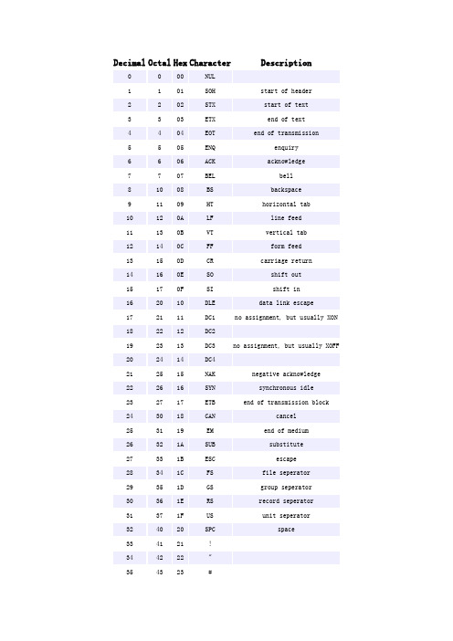
Decimal Octal Hex Character Description1 1 01 SOH start of header3 3 03 ETX end of text5 5 05 ENQ enquiry7 7 07 BEL bell9 11 09 HT horizontal tab11 13 0B VT vertical tab13 15 0D CR carriage return15 17 0F SI shift in17 21 11 DC1 no assignment, but usually XON19 23 13 DC3 no assignment, but usually XOFF21 25 15 NAK negative acknowledge23 27 17 ETB end of transmission block25 31 19 EM end of medium27 33 1B ESC escape29 35 1D GS group seperator31 37 1F US unit seperator33 41 21 !35 43 23 #37 45 25 %39 47 27 '41 51 29 )43 53 2B +45 55 2D -47 57 2F /49 61 31 151 63 33 353 65 35 555 67 37 757 71 39 959 73 3B ;61 75 3D =63 77 3F ?65 101 41 A67 103 43 C69 105 45 E71 107 47 G73 111 49 I75 113 4B K77 115 4D M79 117 4F O81 121 51 Q83 123 53 S85 125 55 U87 127 57 W89 131 59 Y91 133 5B [93 135 5D ]95 137 5F _97 141 61 a99 143 63 c101 145 65 e103 147 67 g105 151 69 i107 153 6B k109 155 6D m111 157 6F o113 161 71 q115 163 73 s117 165 75 u119 167 77 w121 171 79 y123 173 7B {125 175 7D }127 177 7F DEL delete Bin Dec Hex 缩写/字符解释0000 0000 0 00 NUL (null) 空字符0000 0001 1 01 SOH (start of handing) 标题开始0000 0010 2 02 STX (start of text) 正文开始0000 0011 3 03 ETX (end of text) 正文结束0000 0100 4 04 EOT (end of transmission) 传输结束0000 0101 5 05 ENQ (enquiry) 请求0000 0110 6 06 ACK (acknowledge) 收到通知0000 0111 7 07 BEL (bell) 响铃0000 1000 8 08 BS (backspace) 退格0000 1001 9 09 HT (horizontal tab) 水平制表符0000 1010 10 0A LF (NL line feed, new line) 换行键0000 1011 11 0B VT (vertical tab) 垂直制表符0000 1100 12 0C FF (NP form feed, new page) 换页键0000 1101 13 0D CR (carriage return) 回车键0000 1110 14 0E SO (shift out) 不用切换0000 1111 15 0F SI (shift in) 启用切换0001 0000 16 10 DLE (data link escape) 数据链路转义0001 0001 17 11 DC1 (device control 1) 设备控制10001 0010 18 12 DC2 (device control 2) 设备控制20001 0011 19 13 DC3 (device control 3) 设备控制30001 0100 20 14 DC4 (device control 4) 设备控制40001 0101 21 15 NAK (negative acknowledge) 拒绝接收0001 0110 22 16 SYN (synchronous idle) 同步空闲0001 0111 23 17 ETB (end of trans. block) 传输块结束0001 1000 24 18 CAN (cancel) 取消0001 1001 25 19 EM (end of medium) 介质中断0001 1010 26 1A SUB (substitute) 替补0001 1011 27 1B ESC (escape) 溢出0001 1100 28 1C FS (file separator) 文件分割符0001 1101 29 1D GS (group separator) 分组符0001 1110 30 1E RS (record separator) 记录分离符0001 1111 31 1F US (unit separator) 单元分隔符0010 0000 32 20 空格0010 0001 33 21 !0010 0010 34 22 "0010 0011 35 23 #0010 0100 36 24 $0010 0101 37 25 %0010 0110 38 26 &0010 0111 39 27 '0010 1000 40 28 (0010 1001 41 29 )0010 1010 42 2A *0010 1011 43 2B +0010 1100 44 2C ,0010 1101 45 2D -0010 1110 46 2E .0010 1111 47 2F /0011 0000 48 30 00011 0001 49 31 10011 0010 50 32 20011 0011 51 33 30011 0100 52 34 40011 0101 53 35 50011 0110 54 36 60011 0111 55 37 70011 1000 56 38 80011 1001 57 39 90011 1010 58 3A :0011 1011 59 3B ;0011 1100 60 3C <0011 1101 61 3D =0011 1110 62 3E >0011 1111 63 3F ?0100 0000 64 40 @0100 0001 65 41 A 0100 0010 66 42 B 0100 0011 67 43 C 0100 0100 68 44 D 0100 0101 69 45 E 0100 0110 70 46 F 0100 0111 71 47 G 0100 1000 72 48 H 0100 1001 73 49 I 0100 1010 74 4A J 0100 1011 75 4B K 0100 1100 76 4C L 0100 1101 77 4D M 0100 1110 78 4E N 0100 1111 79 4F O 0101 0000 80 50 P 0101 0001 81 51 Q 0101 0010 82 52 R 0101 0011 83 53 S 0101 0100 84 54 T 0101 0101 85 55 U 0101 0110 86 56 V 0101 0111 87 57 W 0101 1000 88 58 X 0101 1001 89 59 Y 0101 1010 90 5A Z 0101 1011 91 5B [ 0101 1100 92 5C \ 0101 1101 93 5D ] 0101 1110 94 5E ^ 0101 1111 95 5F _ 0110 0000 96 60 `0110 0001 97 61 a 0110 0010 98 62 b 0110 0011 99 63 c 0110 0100 100 64 d 0110 0101 101 65 e 0110 0110 102 66 f 0110 0111 103 67 g 0110 1000 104 68 h 0110 1001 105 69 i 0110 1010 106 6A j0110 1011 107 6B k0110 1100 108 6C l0110 1101 109 6D m0110 1110 110 6E n0110 1111 111 6F o0111 0000 112 70 p0111 0001 113 71 q0111 0010 114 72 r0111 0011 115 73 s0111 0100 116 74 t0111 0101 117 75 u0111 0110 118 76 v0111 0111 119 77 w0111 1000 120 78 x0111 1001 121 79 y0111 1010 122 7A z0111 1011 123 7B {0111 1100 124 7C |0111 1101 125 7D }0111 1110 126 7E ~0111 1111 127 7F DEL (delete) 删除ESC键VK_ESCAPE (27)回车键:VK_RETURN (13)TAB键:VK_TAB (9)Caps Lock键:VK_CAPITAL (20)Shift键:VK_SHIFT ()Ctrl键:VK_CONTROL (17)Alt键:VK_MENU (18)空格键:VK_SPACE (/32)退格键:VK_BACK (8)左徽标键:VK_LWIN (91)右徽标键:VK_LWIN (92)鼠标右键快捷键:VK_APPS (93)Insert键:VK_INSERT (45)Home键:VK_HOME (36)Page Up:VK_PRIOR (33)PageDown:VK_NEXT (34)End键:VK_END (35)Delete键:VK_DELETE (46)方向键(←):VK_LEFT (37)方向键(↑):VK_UP (38)方向键(→):VK_RIGHT (39)方向键(↓):VK_DOWN (40)F1键:VK_F1 (112)F2键:VK_F2 (113)F3键:VK_F3 (114)F4键:VK_F4 (115)F5键:VK_F5 (116)F6键:VK_F6 (117)F7键:VK_F7 (118)F8键:VK_F8 (119)F9键:VK_F9 (120)F10键:VK_F10 (121)F11键:VK_F11 (122)F12键:VK_F12 (123)Num Lock键:VK_NUMLOCK (144) 小键盘0:VK_NUMPAD0 (96) 小键盘1:VK_NUMPAD0 (97) 小键盘2:VK_NUMPAD0 (98) 小键盘3:VK_NUMPAD0 (99) 小键盘4:VK_NUMPAD0 (100) 小键盘5:VK_NUMPAD0 (101) 小键盘6:VK_NUMPAD0 (102) 小键盘7:VK_NUMPAD0 (103) 小键盘8:VK_NUMPAD0 (104) 小键盘9:VK_NUMPAD0 (105) 小键盘.:VK_DECIMAL (110) 小键盘*:VK_MULTIPLY (106) 小键盘+:VK_MULTIPLY (107) 小键盘-:VK_SUBTRACT (109) 小键盘/:VK_DIVIDE (111) Pause Break键:VK_PAUSE (19) Scroll Lock键:VK_SCROLL (145)。
亚伟速录略码表精美打印版
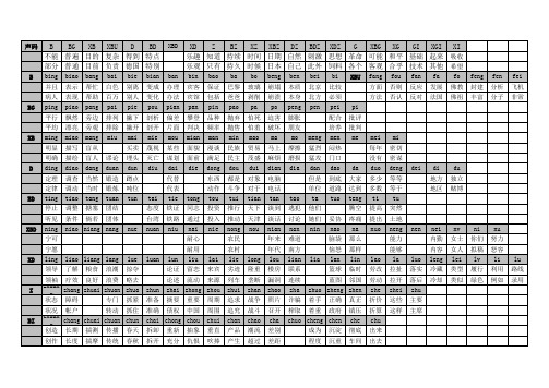
XBD
XD Z BZ XZ XBZ DZ BDZ XDZ G XBG XG GI XGI XI 乐趣 知道 持续 时间 日期 自然 刺激 思想 革命 可能 和平 基础 起来 吸收 乐观 只有 持久 时候 日本 自己 此外 饲料 各个 客观 合乎 技术 其他 希望
bin 宾客 宾馆 pan 攀登 判决 mian 面貌 面前 die bao 保证 包括 pin 品种 频率 man 漫谈 满足 dong 东西 动作 tong 同志 通过 nai 耐心 耐用 tou 投资 投入 nie ba 巴黎 爸爸 pao 抛弃 抛售 min 民族 民主 dou 都是 斗争 tui 推行 推动 nong 农民 农村 lai 来宾 来源 周期 周围 chui 垂直 吹捧 lie 劣迹 列车 zhui 追求 追究 chan 产品 产生 long 隆重 垄断 zhan 战争 战斗 chao 潮流 超过 bo 玻璃 剥削 pa 怕死 怕羞 mao 贸易 茂盛 dui 对象 对于 tian 天下 天津 nou beng 崩塌 崩溃 po 迫害 破坏 ma 马上 麻烦 dian 电脑 电话 tan 谈到 谈话 nian 年来 年代 lou 楼房 漏洞 zhao 照片 召开 cha 差别 差距 tao 逃犯 讨论 nan 难道 南方 lian 联系 连续 zha 诈骗 榨取 着手 着重 成为 程度 lia ben 本质 本身 peng 膨胀 朋友 mo 摩擦 磨损 dia meng 猛烈 猛攻 dan 但是 单位 ta 他们 她们 nin 妥协 nao 脑袋 恼怒 lan 篮球 蓝图 正确 政府 chen 沉淀 沉重 bei 北京 北方 pen bi 比较 必须 pei 配合 培养 men 闷热 门口 dao 到底 道路 tuo da 大家 达到 teng 腾空 疼痛 na 那么 那样 lin 临时 邻国 真正 镇压 che 彻底 车间 lao 劳改 劳动 zhe 折价 折算 chu 出来 出去 pi 批评 批判 me mei 每年 没有 duo 多少 多数 ti 提高 提出 nuo mi 密切 密谋 deng 等等 等于 tu 突然 土地 neng 能力 能够 la 拉扯 拉开 zhei 这些 这样 luo 落实 落后 zhu 主要 主席 nen nei 内勤 内容 leng 冷藏 冷却 nv 女士 女人 lei 类型 类似 ni 你们 拟稿 lv 履行 绿色 nu 努力 怒容 li 利用 例如 lu 路线 录用 dei di 地方 地区 du 独立 赌博 XBU fang 方面 方法 fou 否则 否认 fan 反应 反对 fa 发展 法国 fo 佛教 佛祖 feng 封建 丰富 fen 分析 分子 fei 飞机 非常
TEA5764UK资料

1.General descriptionThe TEA5764UK is a single chip electronically tuned FM stereo radio with Radio Data System (RDS) and Radio Broadcast Data System (RBDS) demodulator and RDS/RBDS decoder for portable application with fully integrated IF selectivity and demodulation.The radio is completely adjustment free and only requires a minimum of small and low cost external components.The radio can tune to the European, US and Japanese FM bands. It has a low power consumption and can operate at a low supply voltage.2.Featuress Chip scale packages High sensitivity due to integrated low noise RF input amplifiers FM mixer for conversion of the US/Europe (87.5 MHz to 108 MHz) and Japanese FM band (76MHz to 90 MHz)to IFs Preset tuning to receive Japanese TV audio up to 108MHz s Auto search tuning, raster 100 kHz s RF automatic gain control circuits LC tuner oscillator operating with low cost fixed chip inductors s Fully integrated FM IF selectivitys Fully integrated FM demodulator; no external discriminators Crystal oscillator at 32768 Hz, or external reference frequency at 32768 Hz s PLL synthesizer tuning systems IF counter; 7-bit output via the I 2C-buss Level detector; 4-bit level information output via the I 2C-bus s Soft mute: signal dependent mute functions Mono/stereo blend: gradual change from mono to stereo, depending on signal s Adjustment-free stereo decoder s Autonomous search tuning function s Standby mode s MPX outputs One software programmable ports Fully integrated RDS/RBDS demodulator in accordance with EN50067s RDS/RBDS decoder with memory for two RDS data blocks provides blocksynchronization and error correction; block data and status information are available via the I 2C-buss Audio pause detectorTEA5764UKFM radio + RDSRev. 02 — 9 August 2005Product data sheets Interrupt flag3.Applicationss FM stereo radio4.Quick reference dataTable 1:Electrical parameters generalThe listed parameters are valid when a crystal is used that meets the requirements as stated in Table46;All RF input values are defined in potential difference, except when EMF is explicitly stated.Symbol Parameter Conditions Min Typ Max Unit SuppliesV CCA analog supply voltage 2.5 2.7 3.3VI CCA analog supply current V CCA=2.5V to 3.3 Voperating mode1213.716mAStandby mode00.11µAV CCD digital supply voltage 2.5 2.7 3.3VI CCD digital supply current V CCD=2.5V to 3.3 Voperating mode0.30.7 1.5mAStandby mode11522.5µA Reference voltageV VREFDIG digital reference voltagefor I2C-bus interface1.65 1.8V CCD VI VREFDIG digital reference supplycurrent operating mode;V VREFDIG=1.65V to V CCD00.51µAGeneralf i(FM)FM input frequency76-108MHz T amb ambient temperature−40-+85°C FM and RDS overall system parametersV sens(EMF)sensitivity EMF valuevoltage f RF = 76 MHz to 108 MHz;∆f=22.5kHz; f mod = 1kHz;(S+N)/N= 26dB; TC deem=75µs;A-weighting filter;B aud=300Hz to15kHz- 2.9 4.4µVIP3in in-band 3rd-orderintercept point ∆f1 = 200 kHz;∆f2 = 400 kHz;f tune=76MHz to 108 MHz;RF agc=off7887-dBµVIP3out out-of-band 3rd-orderintercept point ∆f1 = 4 MHz;∆f2 = 8 MHz;f tune=76MHz to 108 MHz;RF agc=off8793-dBµVS selectivity f tune = 76 MHz to 108 MHz[1]high-side;∆f = +200 kHz3943-dBlow-side;∆f =−200 kHz3236-dBV VAFL left audio output voltageon pin VAFL V RF = 1 mV; L = R;∆f = 22.5 kHz;f mod=1kHz; no pre-emphasis;TC deem=75µs556675mV[1]Low-side and high-side selectivity can be measured by changing the mixer LO injection from high-side to low-side.5.Ordering informationV VAFRright audio output voltage on pin VAFRV RF = 1 mV; L = R;∆f = 22.5 kHz;f mod =1kHz; no pre-emphasis;TC deem =75µs556675mV(S+N)/N(m)maximum signal-to-noiseratio, monoV RF = 1 mV;∆f = 22.5 kHz; L =R;f mod =1kHz; de-emphasis = 75µs;B AF =300 Hz to 15 kHz; A-weighting filter5457-dB(S+N)/N(s)maximum signal-to-noise ratio, stereoV RF = 1 mV;∆f = 67.5 kHz; L =R;f mod =1kHz;∆f pilot = 6.75 kHz;de-emphasis = 75µs; B AF =300 Hz to 15 kHz; A-weighting filter 5054-dBαcschannel separation MST = 0; R = 1 and L = 0 or R =0and L =1; V RF = 30µV; increasing RF input level2733-dBTHD total harmonic distortion V RF = 1 mV;∆f = 75 kHz;f mod =1kHz;DTC =0;B aud =300Hz to 15 kHz; A-weighting filter; mono;L =R; no pilot deviation-0.40.9%V sensRDS sensitivity EMF value∆f = 22.5 kHz; f AF = 1 kHz; L =R;SYM1 = 0 and SYM0 = 0; average over 2000 blocks; block quality rate ≥95%;∆f RDS =2kHz-1730µVTable 1:Electrical parameters generalThe listed parameters are valid when a crystal is used that meets the requirements as stated in Table 46;All RF input values are defined in potential difference, except when EMF is explicitly stated.Symbol ParameterConditionsMin Typ Max Unit Table 2:Ordering informationType numberPackage NameDescriptionVersion TEA5764UKWLB34wafer-level ball grid array; 34 balls; 4× 4× 0.36 mmTEA5764UKxxxx xxxxxxxxxxxxxxxxxxxxxxxxxxxxxx x xxxxxxxxxxxxxx xxxxxxxxxx xxx xxxxxx xxxxxxxxxxxxxxxxxxxxxxx xxxxxxxxxxxxxxxxxxxxxx xxxxx xxxxxx xx xxxxxxxxxxxxxxxxxxxxxxxxxxxxx xxxxxxxxxxxxxxxxxxxxxx xxxxxxxxxxx xxxxxxx xxxxxxxxxxxxxxxxxxx xxxxxxxxxxxxxxxx xxxxxxxxxxxxxx xxxxxx xx xxxxxxxxxxxxxxxxxxxxxxxxxxxxxxxx xxxxxxxxxxxxxxxxxxxxxxxx xxxxxxx xxxxxxxxxxxxxxxxxxxxxxxxxxxxxxxxxxxxxxxxxxxxxx xxxxxxxxxxx xxxxx x xTEA5764UK_2© Koninklijke Philips Electronics N.V . 2005. All rights reserved.Product data sheet Rev. 02 — 9 August 20054 of 64Philips SemiconductorsTEA5764UKFM radio + RDS6.Block diagramFig 1.Block diagram001aab458÷2IF FILTERN1I/Q MIXER 1st FMAGCGAIN STABILIZERCRYSTAL OSCILLATORSOFT MUTESDSF7I 2C-BUS INTERFACEMPX DECODERTUNING SYSTEMmono pilotprog. div out I refref. div outMUXSW PORTVCOE6E7D712 Ω3.7ΩX110 k Ω33 nF33 nF47pF27pF L1120 nH100 pF10 nF12 pFD6C7B7GNDD INTXINTCON2F6G6G5F4G4INTCON1TMUTE VAFR VAFL MPXOUT MPXINGNDA CD2/INTCON3V CCDGNDD GNDD SDABUSENABLEVREFDIGSCL100 k ΩLIMITER LEVEL ADCIF CENTERFREQUENCY ADJUSTDEMODULATORIF COUNTTEA5764UK33 nF33 nF10nFGNDD G3G2F2G1F1E1D2D1C1C2B1FREQIN XTAL CD3FMantennaRFIN1RFIN2GNDRF CAGC V CCA A1B2A2A3A4A5B4A4SWPORTB6A7LOOPSWCPOUTLO1LO2CD1RDS/RBDS DECODERG7INTERFACE REGISTER57 kHz BP FILTERPAUSE DETECTOR33 nF47 k Ω33 nF33 nF PILLPL3L3D1D27.Pinning information7.1Pinning7.2Pin descriptionFig 2.Ball configuration TEA5764UK001aac987TEA5764UKTransparent top viewGF E D C A B 2461357ball A1index areaTable 3:Pin descriptionSymbol Ball DescriptionLOOPSW A1synthesizer PLL loop filter switch output CPOUT B2charge pump output of synthesizer PLL LO1A2local oscillator coil connection 1LO2A3local oscillator coil connection 2CD1A4VCO supply decoupling capacitor PILLP B4pilot PLL loop filterSWPORT A5software programmable port output BUSENABLE A6I 2C-bus enable inputVREFDIG B6digital reference voltage for I 2C-bus signals SCL A7I 2C-bus clock line inputSDA B7I 2C-bus data line input and output n.c.-not connected GNDD C7digital ground GNDD D6digital ground V CCDD7digital supply voltage CD2/INTCON3E7internally connected n.c.-not connectedINTCON2E6internally connected; leave open GNDD F7digital ground INTX G7interrupt flag output n.c.-not connectedINTCON1F6internally connected; leave openTable 3:Pin description …continuedSymbol Ball DescriptionTMUTE G6soft mute time-constant capacitorVAFR G5right audio outputVAFL F4left audio outputMPXOUT G4FM demodulator MPX outputMPXIN G3MPX decoder and RDS decoder MPX inputGNDD G2digital ground; this pin has an internal pull-down resistor of 10 kΩto groundn.c.-not connectedGNDA F2analog groundn.c.-not connectedFREQIN G132.768 kHz reference frequency inputXT AL F1crystal oscillator inputV CCA E1analog supply voltageCD3D2V CCA decoupling capacitorRFIN1D1RF input 1RFIN2C1RF input 2GNDRF C2RF groundCAGC B1RF AGC time-constant capacitorn.c.-not connected8.Functional description8.1Low noise RF amplifierThe LNA input impedance together with the LC RF input circuit defines an FM bandfilter.The gain of the LNA is controlled by the RF AGC circuit.8.2FM I/Q mixerFM quadrature mixer converts FM RF (76MHz to108MHz) to IF.8.3VCOThe varactor tuned LC VCO provides the Local Oscillator (LO) signal for the FMquadrature mixer. The VCO frequency range is 150 MHz to 217 MHz.8.4Crystal oscillatorThe crystal oscillator can operate with a 32.768 kHz clock crystal. The oscillator can beoverridden via the FREFIN pin. When the FREFIN pin is used the oscillator is clockedexternally by a 32.768 kHz signal. Selection between a reference clock or a referencecrystal can be done via the I2C-bus.When a crystal is connected the FREFIN pin must beleft open-circuit, and when pin FREFIN is used a crystal may not be connected. It is notpossible to connect a crystal and apply a frequency via the FREFIN pin in the sameapplication.The crystal oscillator generates the reference frequency for the following:•Reference frequency divider for synthesizer PLL •Timing for the IF counter •Timing for the pause detector•Free running frequency adjustment of the stereo decoder VCO •Centre frequency for adjustment of the IF filters •Clock frequency of the RDS/RBDS decoder8.5PLL tuning systemThe PLL synthesizer tuning system is suitable to operate with a 32.768 kHz reference frequency generated by the crystal oscillator or a reference clock of 32.768 kHz fed into the TEA5764UK. To tune the radio to the required frequency requires the PLL word to be calculated and then programmed to the register. The PLL word is 14 bits long; see Table 20 and T able 21. Calculation of this 14-bit word can be done as follows.Formula for high-side injection:(1)Formula for low-side injection:(2)where:N DEC = decimal value of PLL word f RF = wanted tuning frequency (Hz)f IF = intermediate frequency of 225 kHz f REFS = the reference frequency of 32.768 kHz Example for receiving a channel at 100.1 MHz:(3)The result found using Equation 1 or Equation 2 must always be rounded to the lowest integer value.If rounded down to the lowest integer value of N DEC =12246,the PLL word becomes 2FD6h.This value can be written to register FRQSETLSB or FRQSETMSB via the I 2C-bus and the IC will then either start an autonomous search at this frequency or go to a preset channel at this frequency. When the application is built according to the block diagram shown in Figure 1, and with the preferred components, the PLL will settle to the new frequency within 5ms. The most accurate tuning is accomplished when a search is followed by a preset to the same frequency.N DEC 4f RF f IF +()×f ref --------------------------------------=N DEC 4f RF f IF –()×f ref -------------------------------------=N DEC4100.1106×225103×+()×32768------------------------------------------------------------------------12246.704==The PLL is triggered by writing to any one of the bytes FRQSETMSB, FRQSETLSB,TNCTRL1, TNCTRL2, TESTBITS, TESTMODE.Accurate validation of the PLL locking on the new frequency can take 2ms to 10ms.When a lock is detected, bit LD is set.8.6Band limitsThe TEA5764UK can be switched either to the Japanese FM band or to the US/Europe FM band. Setting bit BLIM to logic 0 the band range is 87.5 MHz to 108 MHz; setting bit BLIM to logic 1 selects the Japanese band range of 76 MHz to 90 MHz.8.7RF AGCThe RF AGC (or wideband AGC) prevents overloading and limits the amount ofintermodulation products created by strong adjacent channels. The RF AGC is on bydefault and can be turned off via the I2C-bus.The TEA5764UK also has an in-band AGC to prevent overloading by the wanted channel.The in-band AGC is always turned on.8.8Local or long distance receiveIf bit LDX=1,the LNA gain is reduced by6dB to prevent distortion when a transmitter is very near. If bit LDX=0, the LNA gain is normal to receive long distance (DX) stations.8.9IF filterA fully integrated IF filter is built-in.8.10FM demodulatorThe FM quadrature demodulator has an integrated resonator to perform the phase shift of the IF signal.8.11IF counterThe received signal is mixed to produce an IF of 225 kHz. The result of the mixing iscounted.A good IF count result indicates that the radio is tuned to a valid channel instead of an image or a channel with much interference. The IF counter outputs a 7-bit countresult via the I2C-bus. The IF counter is continuously active and can be read at any time via the I2C-bus. It also activates a flag when the IF count result is outside the IF countvalid result window; see Section9.1.4.4.Before a tuning cycle is initiated the IF count period can be set to 2 ms or to 15.6 ms by bit IFCTC. When the IF count period is set to 2 ms, initiating the tuning algorithm with a preset (bit SM = 0) will always give an RDS update as shown in Section8.22.1. In case the IF count time is set to 15.6 ms, the tuning flowchart illustrated in Figure3 is used.Once tuned, the IF count period is always 15.6 ms.8.12Voltage level generator and analog-to-digital converterThe voltage level indicates thefield strength received by the antenna.The voltage level is analog-to-digital converted to a 4-bit word and output via the I2C-bus. The ADC level iscontinuously active and can be read at any time via the I2C-bus. It also activates a flagwhen the voltage level falls below a predefined selectable threshold. Bit LHSW allowseither large or small hysteresis steps to be chosen; see Table24 and Section9.1.4.5.When the ADC level is set to 3, its minimum value, the search algorithm will only stop atchannels having a RF level higher than, or equal to, ADC level 3. After completing thesearch algorithm and being tuned to a station, due to hysteresis the effective limit will beset to 0. This means that the continuous ADC level check will never set the LEVFLAG. 8.13Mute8.13.1Soft muteThe low-pass filtered voltage level drives the soft mute attenuator at low RF input levels:the audio output is faded and hence also the noise(see graphs referenced1in Figure15 and Figure17).The soft mute function can also be switched off via the I2C-bus, using bit SMUTE.8.13.2Hard muteThe audio outputs VAFL and VAFR can be hard-muted by bit MU in byte TNCTRL2,which means that they are put into3-state.This can also be done by setting bits Left Hard Mute (LHM) or Right Hard Mute (RHM) in byte TESTBITS, which allows either one or bothchannels to be muted and forces the TEA5764UK to mono mode.When the TEA5764UK is in Standby mode the audio outputs are hard-muted.8.13.3Audio frequency muteThe audio signal is muted by setting bit AFM of the TNCTRL1 register to logic 1. In thesoft mute attenuator the audio signal is blocked and so pins VAFL and VAFR will be attheir DC biasing point with no signal.The audio is automatically muted during an RDS update as shown in the flowchart ofFigure3. When the audio must be muted during Search mode, it is done by setting bitAFM to logic1 before the search action and resetting it to logic 0 afterwards.Setting bit AFM to logic 0 stops the RDS data.8.14MPX decoderThe PLL stereo decoder is adjustment free. It can be switched to mono via the I2C-bus.8.15Signal dependent mono/stereo blend (stereo noise cancellation)If the RF input level decreases, the MPX decoder blends from stereo to mono to limit the output noise. The continuous mono-to-stereo blend can also be programmed via theI2C-bus to an RF level dependent switched mono-to-stereo transition. Stereo noisecancellation can be switched off via the I2C-bus by bit SNC.8.16Software programmable portOne software programmable port (CMOS output) can be addressed via the I2C-bus:Bit SWPM = 1, the software port functions as the output for the FRRFLAG.Bit SWPM= 0, the software port outputs bit SWP of the registers.In Test mode the software port outputs signals according to T able27. Test mode isselected, setting bit TM of byte TESTMODE to logic 1.The software port cannot be disabled by the PUPD bits; see Section8.17.8.17Standby modeThe radio can be put into Standby mode by the Power-Up/Power-Down(PUPD)bits.The RDS part can be turned off separately or both the RDS and the FM part can be turned off.The TEA5764UK is still accessible via the I2C-bus but takes only a low power from thesupply, in Standby mode, the audio outputs are hard-muted.8.18Power-on resetAfter startup of V CCA and V CCD a power-on reset circuit will generate a reset pulse and the registers will be set to their default values. The power-on reset is effectively generated by V CCD.After a power-on reset the TEA5764UK is in Standby mode and the PUPD bits are set to logic 0. After a power-on reset the registers are reset to their default value, except forbyte12R to byte19R and flags DAVFLG, LSYNCFLG and PDFLAG. To reset these, theRDS part must be turned on by setting PUPD. After setting PUPD to logic 1, it will take0.9ms to start-up the TEA5764UK and set these registers to their default value.The power supplies can be switched on in any order.When the supply voltage V CCA and V CCD are at 0 V, all I/Os, the audio outputs and thereference clock input are high-ohmic.8.19RDS/RBDS8.19.1RDS/RBDS demodulatorA fully integrated RDS/RBDS demodulator which uses the reference frequency(32.678Hz) of the PLL synthesizer tuning system. The RDS demodulator recovers andregenerates the continuously transmitted RDS or RBDS data stream of the multiplexsignal (MPXRDS) and provides the signals clock (RDCL), data (RDDA) for furtherprocessing by the integrated RDS decoder.8.19.2RDS data and clock directThe RDS demodulator retrieves the RDS data and clock signals, this data can be putdirectly onto pins VAFL and VAFR by setting bit RDSCDA to logic 1.8.19.2.1RDS/RBDS decoderThe RDS decoder provides block synchronization, error correction and flywheel functionfor reliable extraction of RDS or RBDS block data. Different modes of operation can beselected tofit different application requirements.Availability of new data is signalled by bitDAVFLG and output pin INTX which generates an interrupt. Up to two blocks of data andstatus information are available via the I2C-bus in a single transmission.The behavior of the DAVFLG is described in Section10.8.20Audio pause detectorThe audio pause detector monitors the audio modulation for pauses and responds to lowlevels.The modulation threshold can be adjusted in4steps of4dB by control bits PL[1:0].The minimum time for detecting a pause can be adjusted by control bits PT[1:0]as shownin T able38.When a pause occurs,flag PDFLAG is set to logic1and a hardware interruptis generated; see Section9.1.4.6.8.21Auto search and Preset modeIn Search mode the TEA5764UK can search channels automatically (see Figure3).Before starting a search or a preset, the INTMSK register must be reset and only theFRRMSK must be set. This allows the microprocessor to be interrupted only when thesearch or preset algorithm is ready.Fig 3.Flowchart auto search or preset001aab461during a preset mute is always activesearch mode is default not mutedunless AHLSI is setBLFLAG = 0FRRFLAG = 1no mute reset flagsset PLL frequencyincrement current_pllby 100 kHz decrement current_pll by 100 kHz wait for PLL to settleset LEVFLAG truefalse level OKstarttrue falseIF OKtruefalse AHLSIfalsesearch uptruetruefalse band limittruefalse search modeBLFLAG = 0FRRFLAG = 1mute BLFLAG = 1FRRFLAG = 1no mute8.21.1Search modeSearch mode is initiated by setting bit SM in byte FRQSETMSB to logic 1. The searchdirection is set by bit SUD; SUD=0 (search down), bit SUD = 1 (search up). The tunerstarts searching at the frequency set in bytes FRQSETLSB and FRQSETMSB. TheSearch Stop Level (SSL) bits define the field strength level at which a desired channel isdetected.The tuner will stop on a channel with afield strength equal to or higher than this reference level and then checks the IF frequency; when both are valid, the search stops(Note that this depends on bit AHLSI described in Figure3). If the level check or theIF-count fails, the search continues. If no channels are found, the TEA5764UK stopssearching when it has reached the band limit,setting the BLFLAG HIGH.A search always stops when the FRRFLAG is set and on the occurrence of a hardware interrupt, thisprocedure is shown in Figure3.The search algorithm can stop at a frequency that is offset from the IF by up to amaximum of 12kHz. The maximum offset can be limited to 8kHz by applying a preset.For optimum tuning, it is recommended that a preset is applied after a search and whenthe found frequency has an offset that is above 8kHz.After this interrupt the TEA5764UK will not update the tuner registers for a period of 15ms. The state of the TEA5764UK can be checked by reading the bytes of INTFLAG,FRQCHKMSB, FRQCHKLSB, TNCTRL1 and TNCTRL2.Table4 shows the possiblestates of these registers after an auto search.Table 4:Tuner truth table[1]IFFLAG BLFLAG FRRFLAG Comment000if pin INTX has gone LOW and only IFMSK, FRRMSK andBLMSK were set then this cannot occur001channel found during search / preset; FRRMSK set010not a valid state011 a valid channel found and the band limit has been reachedduring a search; BLMSK or FRRMSK set100not a valid state101 a preset or search has occurred but the wanted channel has avalid RSSI level but fails the IF count when AHLSI was set tologic1; HLSI must be toggled and a new PLL value must beprogrammed; FRRMSK set110not a valid state111band limit is reached during search; no valid channel found;BLMSK or FRRMSK set[1]This table is valid until 30.6 ms after the tuning cycle has completed. It shows the outcome of the flagregister when a read is done after pin INTX goes LOW on condition that no mask bit other than FRRMSK isset.8.21.2Preset modeA preset occurs by setting bit SM to logic0and writing a frequency to byte FRQSETMSB.The tuner jumps to the selected frequency and sets the FRRFLAG when it is ready.After this interrupt the TEA5764UK will not update the tuner registers for a period of15ms. The state of the TEA5764UK can be checked by reading registers: INTFLAG,FRQCHKLSB, FRQCHKMSB, TNCTRL1 and TNCTRL2.Table4 shows the possiblestates after a preset.8.21.3Auto high-side and low-side injection stop switchWhen a channel is searched or a preset is done,reception can sometimes improve wheninjection is done at the other side of the wanted channel.The TEA5764UK has bit HLSI which toggles the injection of the local oscillator fromhigh-side (bit HLSI = 1) to low-side (bit HLSI = 0). When bit HLSI is toggled, a new PLLsetting must be sent to the TEA5764UK.When bit AHLSI is set to logic 1,the search /preset algorithm will stop after a channel hasa valid RSSI level check but fails the IF count. The microprocessor can now respond bytoggling the HLSI switch and sending a new PLL value to the tuner.8.21.4Muting during search or presetDuring a preset the tuner is always muted and this is implemented by the algorithm.A search is not muted by default unless bit AFM = 1 or bit AHLSI = 1.When bit AHLSI = 1 and the tuner stopped during a preset or a search because of awrong IF count, the tuner stays muted; this allows the microprocessor to switch from thehigh to low setting quietly and wait for the new result.The tuner is always muted if bit AFM = 1 and is independent of a search or a preset. Asearch can be muted by setting bit AFM to logic 1before a search is initiated and resettingit to logic 0 when the tuner is ready (only set bit FRRMSK when initiating a search orpreset).All these mute actions are done by blocking the audio signal inside the soft muteattenuator, the audio output will keep its DC level and stay low-ohmic i.e. 50Ω (a hardmute set by bit MU will cause a plop).8.22RDS update/alternative frequency jumpA channel which transmits RDS data can have alternative channels which have the sameinformation. These alternative channel frequencies are in the RDS data, so themicroprocessor can read the alternative frequencies and store them in a memory.The tuner can perform an RDS update. This is very similar to a preset, but with a 2 ms IFcount time.The tuner will jump to the alternative frequency and check the level and the IFcount using a 2ms count time.When the RSSI level check is above the specified level andthe IF count result is within the limits, then the tuner will stay at the alternative frequencyand stay muted, the microprocessor can now decide what to do. If the alternativefrequency is not valid it will jump back to the frequency it came from.Fig 4.Switch LO from high-side injection to low-side injection using bit HLSI001aab460image on high-sidewanted channel switch LO from high-side to low-side image on low-sideThe algorithm will finish with the FRRFLAG being set and an interrupt is generated. Afterthis interrupt the TEA5764UK will not measure the IF count for a period of 15 ms. 15 msafter completing a RDS jump, a measurement of the IF count will start and hence the IFcount result and the IFFLAG will be updated 30.6 ms after completing the algorithm. Thelevel measurement will start immediately after the tuning algorithm, so the LEVFLAG willbe updated 500µs after the algorithm. The state of the TEA5764UK can be checked byreading registers INTFLAG, FRQCHKLSB, FRQCHKMSB, IFCHK and LEVCHK.Table5shows the possible states after an auto search,Figure5 is a flowchart showing how theRDS is updated.8.22.1Muting during RDS updateAn RDS update (AF jump) is always muted. There are two possibilities for leaving thealgorithm:•The tuner jumps to an alternative frequency which is not valid (according to the specified SSL limit and fixed IF counter limits) and jumps back, then it willautomatically unmute.•Or the tuner jumps to a valid alternative frequency and stays there. Now it does not unmute. The microprocessor can unmute or it keeps the tuner muted and can checkfor the presence of RDS data. The valid way to unmute is to apply a preset to thecurrent frequency (an IF count time of 15.6 ms is used at preset, which gives a moreaccurate IF count result than the result obtained by the AF jump,where2ms is used).Table 5:RDS update truth table[1]IFFLAG BLFLAG FRRFLAG Comment000if pin INTX is LOW and only IFMSK,FRRMSK and BLMSK wereset then this cannot occur001alternative frequency jump successful; radio is tuned to thealternative frequency and stays muted010not a valid state011not a valid state100not a valid state101AF jump has occurred but the wanted channel fails the IF count;the PLL will be set back to the old value110not a valid state111if pin INTX is LOW and only IFMSK,FRRMSK and BLMSK wereset then this cannot occur[1]This table is valid until 30.6 ms after an RDS update has completed. It shows the outcome of the flagregister when a read is done after pin INTX has gone LOW and on condition that only mask bit FRRMSK isset.。
FPGA可编程逻辑器件芯片EP3C40F484C8N中文规格书
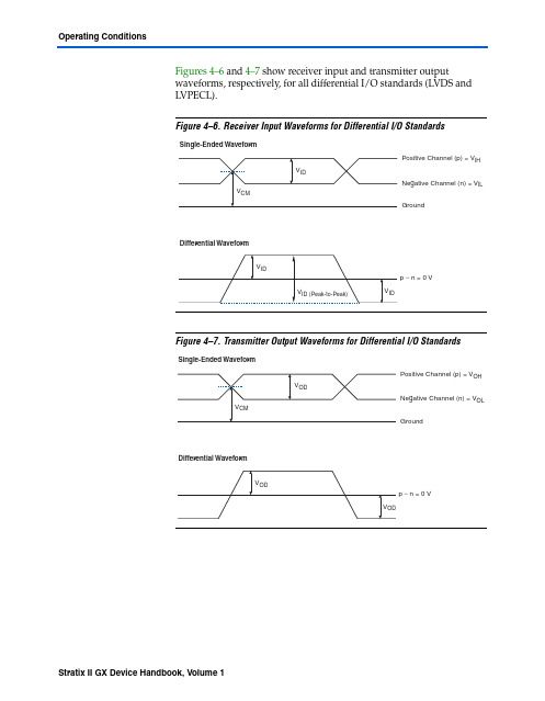
Figures4–6 and 4–7 show receiver input and transmitter output waveforms, respectively, for all differential I/O standards (LVDS and LVPECL).Figure4–6.Receiver Input Waveforms for Differential I/O StandardsFigure4–7.Transmitter Output Waveforms for Differential I/O StandardsPin CapacitanceTable 4–51 shows the Stratix II GX device family pin capacitance.Table 4–50.Series and Differential On-Chip Termination Specification for Left I/O Banks Note (1)SymbolDescription Conditions Resistance ToleranceCommercial Max Industrial Max Unit 25-Ω R S3.3/2.5Internal series termination without calibration (25-Ω setting )V CCIO = 3.3/2.5V ±30 ±30%50-Ω R S3.3/2.5/1.8Internal series termination without calibration (50-Ω setting )V CCIO = 3.3/2.5/1.8V ±30 ±30%50-Ω R S 1.5Internal series termination without calibration (50-Ω setting )V CCIO = 1.5V ±36 ±36%R D Internal differential termination forLVDS (100-Ω setting)V CCIO = 2.5 V ±20 ±25%Note to Table 4–50:(1)On-chip parallel termination with calibration is only supported for input pins.Table 4–51.Stratix II GX Device CapacitanceNote (1)SymbolParameter Typical Unit C IOTBInput capacitance on I/O pins in I/O banks 3, 4, 7, and 8. 5.0pF C IOLInput capacitance on I/O pins in I/O banks 1 and 2, including high-speed differential receiver and transmitter pins. 6.1pF C CLKTBInput capacitance on top/bottom clock input pins: CLK[4..7] and CLK[12..15]. 6.0pF C CLKLInput capacitance on left clock inputs: CLK0 and CLK2. 6.1pF C CLKL+Input capacitance on left clock inputs: CLK1 and CLK3. 3.3pF C OUTFB Input capacitance on dual-purpose clock output/feedback pins in PLLbanks 11 and 12. 6.7pFNote to Table 4–51:(1)Capacitance is sample-tested only. Capacitance is measured using time-domain reflections (TDR). Measurementaccuracy is within ±0.5pF.DC and Switching CharacteristicsPower Consumption Altera offers two ways to calculate power for a design: the Excel-based PowerPlay early power estimator power calculator and the Quartus® II PowerPlay power analyzer feature.The interactive Excel-based PowerPlay early power estimator is typically used prior to designing the FPGA in order to get an estimate of device power. The Quartus II PowerPlay power analyzer provides better quality estimates based on the specifics of the design after place-and-route is complete. The power analyzer can apply a combination of user-entered, simulation-derived and estimated signal activities which, combined with detailed circuit models, can yield very accurate power estimates.In both cases, these calculations should only be used as an estimation of power, not as a specification.f For more information on PowerPlay tools, refer to the PowerPlay EarlyPower Estimators (EPE) and Power Analyzer, the Quartus II PowerPlayAnalysis and Optimization Technology, and the PowerPlay Power Analyzerchapter in volume 3 of the Quartus II Handbook. The PowerPlay earlypower estimators are available on the Altera web site atwww.altera. com.1See Table4–23 on page42 for typical I CC standby specifications. Timing Model The DirectDrive technology and MultiTrack interconnect ensurepredictable performance, accurate simulation, and accurate timinganalysis across all Stratix II GX device densities and speed grades. Thissection describes and specifies the performance, internal, external, andPLL timing specifications.All specifications are representative of worst-case supply voltage andjunction temperature conditions.Preliminary and Final TimingTiming models can have either preliminary or final status. The Quartus IIsoftware issues an informational message during the design compilationif the timing models are preliminary. Table4–52 shows the status of theStratix II GX device timing models.Preliminary status means the timing model is subject to change. Initially,timing numbers are created using simulation results, process data, andother known parameters. These tests are used to make the preliminarynumbers as close to the actual timing parameters as possible.DC and Switching Characteristics。
2014年海外游戏视频直播平台案例研究报告——AfreecaTV

2006.03 AfreecaTV平台建立 2007.12 推出增值道具 2008.10 AfreecaTV达到 损益平衡点
市场拓展
新的业务: 2013.09 推出手游中心
逐步完善
2009.01 获得棒球、足球等专 业体育赛事的转播权 2009.03 将音乐直播和游戏直 播分开 2009.12 推出手机版(iOS) 2010.10 推出安卓版
海外市场:
2013.01 成立日本子公司 2014.03 在日本推出AfreecaTV平 台 2015.01 计划在台湾(和红心辣椒 合资)、东南亚、美国成 立子公司
5 5
AfreecaTV平台用户规模
PC端用户增长停滞,手机端渐增
得益于智能手机的迅速普及和韩国的网络速度,AfreecaTV的手机端用户呈现不断增长趋势,目前手机客户端下载量已突 破2500万次。PC端和手机端的日访问用户数分别超过100万和250万。
贴纸
付费
1. 赠送给主播后成为该主播的支持者 2. 聊天窗内以特殊颜色显示 1. 50个可以兑换自身的QuickView会员资格(7 天) 2. 可赠送给主播,但不成为粉丝或支持者
可用来兑换直播功能:例如增加频 道人数上限、提升频道清晰度等
约0.56 RMB/个
巧克力
下载/登陆/充值 Afreeca手游获得
AfreecaTV
1994
PC通信
(已终止)
2002
2006
2007
网络硬盘
(已出售)
2011
2012
2013
2014
(合并后又拆分成 独立公司)
网络安全
已结束业务
运营PC网游《超级跑跑》
(版权已出售给Smilegate)
AD8512TRZ-EP JFET 操作放大器说明书

AD8512TRZ-EPPrecision, Very Low Noise, Low Input Bias Current,Wide Bandwidth JFET Operational AmplifierEnhanced ProductAD8512-EPRev. 0 Document FeedbackInformation furnished by Analog Devices is believed to be accurate and reliable. However , noresponsibility is assumed by Analog Devices for its use, nor for any infringements of patents or other rights of third parties that may result from its use. Specifications subject to change without notice. No license is granted by implication or otherwise under any patent or patent rights of Analog Devices. T rademarks and registered trademarks are the property of their respective owners.One Technology Way, P.O. Box 9106, Norwood, MA 02062-9106, U.S.A. Tel: 781.329.4700 ©2018 Analog Devices, Inc. All rights reserved. Technical Support FEATURESFast settling time: 500 ns to 0.1%Low offset voltage: 1.0 mV maximum at V S = ±15 V Low offset voltage drift: 1.7 µV/°C typicalLow input bias current: 25 pA typical at V S = ±15 V Dual-supply operation: ±5 V to ±15 VLow noise: 8.0 nV/√Hz typical at f = 1 kHz Low distortion: 0.0005% No phase reversal Unity gain stableENHANCED PRODUCT FEATURESSupports defense and aerospace applications (AQEC standard)Military temperature range (−55°C to +125°C) Controlled manufacturing baseline 1 assembly/test site 1 fabrication siteProduct change notificationQualification data available on requestAPPLICATIONSInstrumentation Multipole filtersPrecision current measurementPhotodiode amplifiers Military communication AvionicsPIN CONFIGURATION–IN A +IN A V –V+–IN B+IN B17170-002Figure 1.GENERAL DESCRIPTIONThe AD8512-EP is a dual-precision JFET amplifier that features low offset voltage, input bias current, input voltage noise, and input current noise.The combination of low offsets, low noise, and very low input bias currents makes these amplifiers especially suitable for high impedance sensor amplification and precise currentmeasurements using shunts. The combination of dc precision, low noise, and fast settling time results in superior accuracy in flight instruments, electronic measurement, and aviation equipment. Unlike many competitive amplifiers, the AD8512-EP maintains its fast settling performance even with substantial capacitive loads. Unlike many older JFET amplifiers, the AD8512-EP does not suffer from output phase reversal wheninput voltages exceed the maximum common-mode voltage range.Fast slew rate and great stability with capacitive loads make the AD8512-EP suitable for high performance filters. Low input bias currents, low offset, and low noise result in a wide dynamic range of photodiode amplifier circuits. Low noise and distortion, high output current, and excellent speed make the AD8512-EP a great choice for military communication applications. The AD8512-EP is available in an 8-lead narrow SOIC_N package. The AD8512-EP is specified over a military temperature range of −55°C to +125°C. Additional application and technical information can be found in the AD8512 data sheet.AD8512-EPEnhanced ProductRev. 0 | Page 2 of 7TABLE OF CONTENTSFeatures .............................................................................................. 1 Enhanced Product Features ............................................................ 1 Appl ications ....................................................................................... 1 Pin Configuration ............................................................................. 1 General Description ......................................................................... 1 Revision History ............................................................................... 2 Specifications ..................................................................................... 3 Electrical Characteristics . (4)Absolute Maximum Ratings ............................................................5 Thermal Resistance .......................................................................5 ESD Caution...................................................................................5 Typical Performance Characteristics ..............................................6 Outline Dimensions ..........................................................................7 Ordering Guide .. (7)REVISION HISTORY8/2018—Revision 0: Initial VersionEnhanced Product AD8512-EP SPECIFICATIONSV S = ±5 V, V CM = 0 V, T A = 25°C, unless otherwise noted.Table 1.Parameter Symbol Test Conditions/Comments Min Typ Max Unit INPUT CHARACTERISTICSOffset Voltage V OS0.1 0.9 mV−55°C < T A < +125°C 1.8 mVInput Bias Current I B21 75 pA−55°C < T A < +85°C 0.7 nA−55°C < T A < +125°C 7.5 nAInput Offset Current I OS 5 50 pA−55°C < T A < +85°C 0.3 nA−55°C < T A < +125°C 0.5 nAInput CapacitanceDifferential 12.5 pF Common Mode 11.5 pFInput Voltage Range −2.0 +2.5 V Common-Mode Rejection Ratio CMRR V CM = −2.0 V to +2.5 V 86 100 dBLarge-Signal Voltage Gain A VO R L = 2 kΩ, V O = −3 V to +3 V 65 107 V/mV Offset Voltage Drift (T C V OS) ΔV OS/ΔT 1.7 12 µV/°C OUTPUT CHARACTERISTICSOutput Voltage High V OH R L = 10 kΩ 4.1 4.3 VR L = 2 kΩ 3.9 4.2 VR L = 600 Ω 3.7 4.1 VOutput Voltage Low V OL R L = 10 kΩ, −55°C < T A < +125°C −4.9 −4.7 VR L = 2 kΩ, −55°C < T A < +125°C −4.9 −4.5 VR L = 600 Ω, −55°C < T A < +125°C −4.8 −4.2 VOutput Current I OUT ±40 ±54 mA POWER SUPPLYPower Supply Rejection Ratio PSRR V S = ±4.5 V to ±18 V 86 130 dB Supply Current/Amplifier I SY V O = 0 V 2.0 2.3 mA−55°C < T A < +125°C 2.5 mA DYNAMIC PERFORMANCESlew Rate SR R L = 2 kΩ 20 V/µs Gain Bandwidth Product GBP 8 MHz Settling Time t S To 0.1%, 0 V to 4 V step, G = +1 0.4 µsTotal Harmonic Distortion (THD) + Noise THD + N 1 kHz, G = +1, R L = 2 kΩ 0.0005 % Phase Margin φM 44.5 Degrees NOISE PERFORMANCEVoltage Noise Density e n f = 10 Hz 34 nV/√Hzf = 100 Hz 12 nV/√Hzf = 1 kHz 8.0 10 nV/√Hzf = 10 kHz 7.6 nV/√Hz Peak-to-Peak Voltage Noise e n p-p 0.1 Hz to 10 Hz bandwidth 2.4 5.2 µV p-pRev. 0 | Page 3 of 7AD8512-EPEnhanced ProductRev. 0 | Page 4 of 7ELECTRICAL CHARACTERISTICSV S = ±15 V , V CM = 0 V , T A = 25°C, unless otherwise noted. Table 2.ParameterSymbol Test Conditions/Comments Min Typ Max Unit INPUT CHARACTERISTICS Offset Voltage V OS0.1 1.0 mV−55°C < T A < +125°C 1.8 mV Input Bias Current I B25 80 pA −55°C < T A < +85°C 0.7 nA−55°C < T A < +125°C 10 nA Input Offset Current I OS6 75 pA −55°C < T A < +85°C 0.3 nA−55°C < T A < +125°C 0.5 nA Input Capacitance Differential 12.5 pF Common Mode11.5pF Input Voltage Range−13.5 +13.0 V Common-Mode Rejection Ratio CMRR V CM = −12.5 V to +12.5 V 86 108 dB Large-Signal Voltage Gain A VO R L = 2 kΩ, V CM = 0 V, V O = −13.5 V to +13.5 V 115 196 V/mV Offset Voltage DriftΔV OS /ΔT 1.7 12 µV/°C OUTPUT CHARACTERISTICSOutput Voltage High V OH R L = 10 kΩ 14.0 14.2 V R L = 2 kΩ 13.8 14.1 V R L = 600 Ω13.5 13.9 VR L = 600 Ω, −55°C < T A < +125°C 11.4V Output Voltage Low V OL R L = 10 kΩ, −55°C < T A < +125°C −14.9 −14.6 V R L = 2 kΩ, −55°C < T A < +125°C –14.8 −14.5 V R L = 600 Ω−14.3 −13.8 VR L = 600 Ω, −55°C < T A < +125°C −12.1 V Output Current I OUT ±70 mA POWER SUPPLYPower Supply Rejection Ratio PSRR V S = ±4.5 V to ±18 V 86 dB Supply Current/Amplifier I SY V O = 0 V2.2 2.5 mA−55°C < T A < +125°C 2.6 mA DYNAMIC PERFORMANCESlew RateSR R L = 2 kΩ 20 V/µs Gain Bandwidth Product GBP8 MHz Settling Time t S To 0.1%, 0 V to 10 V step, G = +1 0.5 µsTo 0.01%, 0 V to 10 V step, G = +1 0.9 µs Total Harmonic Distortion (THD) + Noise THD + N 1 kHz, G = +1, R L = 2 kΩ 0.0005 %Phase MarginφM 52 Degrees NOISE PERFORMANCEVoltage Noise Density e n f = 10 Hz 34 nV/√Hz f = 100 Hz 12 nV/√Hz f = 1 kHz 8.0 10 nV/√Hzf = 10 kHz7.6 nV/√Hz Peak-to-Peak Voltage Noisee n p-p0.1 Hz to 10 Hz bandwidth2.45.2µV p-pEnhanced ProductAD8512-EPRev. 0 | Page 5 of 7ABSOLUTE MAXIMUM RATINGSTable 3.Parameter Rating Supply Voltage ±18 V Input Voltage ±V SPower DissipationSee Figure 2 Storage Temperature Range −65°C to +150°C Operating Temperature Range −55°C to +125°C Junction Temperature Range−65°C to +150°C Lead Temperature (Soldering, 10 sec) 300°C Electrostatic Discharge (Human Body Model)2000 VStresses at or above those listed under Absolute Maximum Ratings may cause permanent damage to the product. This is a stress rating only; functional operation of the product at these or any other conditions above those indicated in the operational section of this specification is not implied. Operation beyond the maximum operating conditions for extended periods may affect product reliability.THERMAL RESISTANCEThermal performance is directly linked to printed circuit board (PCB) design and operating environment. Careful attention to PCB thermal design is required.θJA is the natural convection junction to ambient thermalresistance measured in a one cubic foot sealed enclosure. θJC is the junction to case thermal resistance. Table 4. Thermal ResistancePackage Type 1 θJA θJC Unit R-8158 43 °C/W1Thermal impedance simulated values are based on a JEDEC 2S2P thermal test board. See JEDEC JESD-51.1.000.10.20.30.40.50.60.70.80.9–55–35–15525456585105125M A X I M U M P O W E R D I S SI P A T I O N (W )AMBIENT TEMPERATURE (°C)17170-040Figure 2. Maximum Power Dissipation vs. Ambient TemperatureESD CAUTIONAD8512-EPEnhanced ProductRev. 0 | Page 6 of 7TYPICAL PERFORMANCE CHARACTERISTICST C V OS (µV/°C )N U M B E R O F A M P L I F I E R S10151.032.03.04.05.00.5 1.5 2.5 3.5 4.5 5.56.017170-009Figure 3. T C V OS DistributionTEMPERATURE (°C )I N P U T B I AS C U R R E N T (p A )–551101001k–3510k100k–1552545658510512517170-010Figure 4. Input Bias Current vs. TemperatureTEMPERATURE (°C )I N P U T O FF S E T C U R R E N T (p A )–550.010.1110–351001k–1552545658510512517170-011Figure 5. Input Offset Current vs. TemperatureTEMPERATURE (°C )S U P P L Y CU R R E N T P E R A M P L I F I E R (m A )–551.00–352.502.252.001.751.501.25–1552545658510512517170-015Figure 6. Supply Current per Amplifier vs. TemperatureEnhanced ProductAD8512-EPRev. 0 | Page 7 of 7OUTLINE DIMENSIONSCONTROLLING DIMENSIONS ARE I N MILLIMETERS;INCH DIMENSIONS (IN PARENTHESES)ARE ROUNDED-OFF MILLIMETER EQUIVALENTS FOR REFERENCE ONLY AND ARE NOT APPROPRIATE FOR USE IN DESIGN.COMPLIANT TO JEDEC STANDARDS MS-012-AA012407-A0.25(0.0098)0.17(0.0067)0.40(0.0157)45°Figure 7. 8-Lead Standard Small Outline Package [SOIC_N]Narrow Body (R-8)Dimensions shown in millimeters and (inches)ORDERING GUIDEModel 1Temperature Range Package DescriptionPackage Option Marking Code AD8512TRZ-EP −55°C to +125°C 8-Lead Standard Small Outline Package [SOIC_N] R-8 DNL AD8512TRZ-EP-R7−55°C to +125°C 8-Lead Standard Small Outline Package [SOIC_N] R-8 DNL1Z = RoHS Compliant Part©2018 Analog Devices, Inc. All rights reserved. Trademarks and registered trademarks are the property of their respective owners. D17170-0-8/18(0)AD8512TRZ-EP。
虎牙直播签约协议
虎牙直播签约协议篇一:各大平台主播利润分成各大直播平台主播的收入计算方式网易CCCC主播运营政策一、具体待遇政策(一)主播待遇l 收入日结(日结免税)主播需用签约直播帐号登录网易宝,并实名认证及绑定银行卡,系统将根据主播后台金豆自动日结。
礼物产生多少金豆主播即获得多少金豆,1000金豆=1元。
用户送单价2元以下礼物:1元消费主播获得450金豆用户送单价2元以上礼物:1元消费主播获得500金豆l 主播底薪(月结缴税)主播月兑换不低于1500元,满足其他软性标准可发放1500元底薪。
主播月兑换不低于2500元,满足其他软性标准可发放2500元底薪。
具体主播软性标准如下:1:必须有完整的设备:声卡、电容麦、高清摄像头(非红外): 2:具备优秀的主麦能力,有突出才艺,能迅速调动房间气氛3:视频清晰,背景整洁,形象佳,有人缘4:月有效天数=22天,一个月麦时=55小时(主麦开视频直播2小时等于1个有效天,每天最多累计1个有效天)5:不违反站内主播管理制度l 大主播日结激励(日结免税)主播当日金豆兑换大于等于1000元,额外奖励当日总兑换的20% 主播当日金豆兑换大于等于10000元,额外奖励当日总兑换的40%web端直播间1)来疯说明1)本月累计时长:播客每月总的直播时长2)时薪:播客每直播一小时获得10元薪金3)本月底薪:本月累计时长*时薪,本月直播时长须=30小时,礼物兑换佣金须=200元才可享受底薪;首月开播=10小时即可享受底薪,底薪最高上限1000元4)本月累计星豆:播客本月所收到星豆的总和,不包括“兑换成星币的这部分星豆” 5)本月兑换佣金:播客每月所收到星豆总和兑换人民币,兑换比例42%(10000星豆=7元)6)本月获得奖金:兑换佣金*40.0%,兑换佣金=2000才给予发放奖金,少于2000则不享有奖金待遇(系统会提示播客享有奖金待遇所差的星豆数量),奖金最高上限100000元1、播客薪资=时薪+兑换佣金+奖金2、机构合作必须以公司性质合作,每月10个工作日之前发上月结算薪资。
半静态调度SPS专题
Semi-Persistent Scheduling(SPS,半永久性调度)一、SPS简介Semi-Persistent Scheduling,简称SPS半永久性调度,又称为半静态调度。
与动态调度时每个TTI为UE分配一次无线资源不同(通过PDCCH指定),SPS允许半静态配置无线资源,并将该资源周期性地分配给某个特定UE。
简单地说,eNodeB在某个TTI使用SPS C-RNT加扰的PDCCH指定UE所使用的无线资源(这里将其称为SPS资源),每过一个周期,UE就使用该SPS资源来收或发数据。
eNodeB 无需在该子帧(这里将其称为SPS子帧)下发PDCCH来指定分配的资源。
由于SPS有“一次分配,多次使用”的特点,不需要在每个TTI都为UE下发DCI(包括上行或下行的DCI),从而降低了对应的PDCCH开销。
SPS灵活性稍差,但控制信令开销小,适合突发特征不明显,有保证速率要求的业务,主要用于周期性小包业务,如VoIP。
这类业务的timing 和所需的无线资源都是可预测的。
目前中兴只针对QCI为1的VoIP语音业务进行SPS协议规定只有PCell支持SPS这是因为SPS主要应用于低速业务,负载低,没有必要使用多个载波单元。
中兴eNodeB支持20ms和40ms的半静态调度周期。
当半静态调度周期配置为20ms时,语音报文在eNodeB的调度时延较少,VoLTE用户从而可以获得更高的语音质量;当半静态调度周期配置为40ms时,eNodeB支持的SPS用户数翻倍,但语音报文在eNodeB的调度时延将增加,VOLTE 用户的语音质量将稍有下降。
SPS周期由eNodeB通过RRC消息传送给UE。
VoIP业务的通话期与静默期状态由PDCP 层进行判决,判决为通话期时, 激活半静态调度;判决为静默期时,释放已分配的半静态资源;当业务从静默期转为通话期时,需要重新激活半静态调度。
在以下场景下, eNodeB 采用动态调度作为半静态调度的补充:半静态调度期间的QCI1承载上的大包,RB资源过载时,会动态调度过载的资源。
- 1、下载文档前请自行甄别文档内容的完整性,平台不提供额外的编辑、内容补充、找答案等附加服务。
- 2、"仅部分预览"的文档,不可在线预览部分如存在完整性等问题,可反馈申请退款(可完整预览的文档不适用该条件!)。
- 3、如文档侵犯您的权益,请联系客服反馈,我们会尽快为您处理(人工客服工作时间:9:00-18:30)。
生命是永恒不断的创造,因为在它内部蕴含着过剩的精力,它不断流溢,越出时间和空间的界限,它不停地追求,以形形色色的自我表现的形式表现出来。
--泰戈尔UA741中文资料
uA741M,uA741I,uA741C(单运放)是高增益运算放大器,用于军事,工业和商业应用.这类单片硅集成电路器件提供输出短路保护和闭锁自由运作。
这些类型还具有广泛的共同模式,差模信号范围和低失调电压调零能力与使用适当的电位。
uA741M,uA741I,uA741C芯片引脚和工作说明:
1和5为偏置(调零端),2为正向输入端,3为反向输入端,4接地,6为输出,7接电源8空脚
温度等级
specified) 电气特性
虚拟通道连接= ± 15V ,Tamb = 25 ℃(除非另有说明)
UA741/ LM741应用电路:
图6 12V的电池监视器图7 低功耗放大器
图8 741驱动三极管的5瓦功率放大器
图9 自动感光电路图
图10 夜间自动感光电路图
图11 声音探测器
图12 数字/模拟输出接口电路。