TracTrix 5 Software Manual
DarkFX Strip 510用户手册说明书
HIGH INTENSITY 365nm ULTRAVIOLET LIGHT RISK OF EXPOSURE TO ULTRAVIOLET RADIATION AVOID DIRECT EYE AND SKIN EXPOSURE DO NOT OPERATE FIXTURE WITHOUT EXTERNAL COVER AND CAUTION PROTECTIVE LENS INSTALLED. DO NOT OPERATE FIXTURE WITH DAMAGED EXTERNAL COVER AND/OR PROTECTIVE LENS.
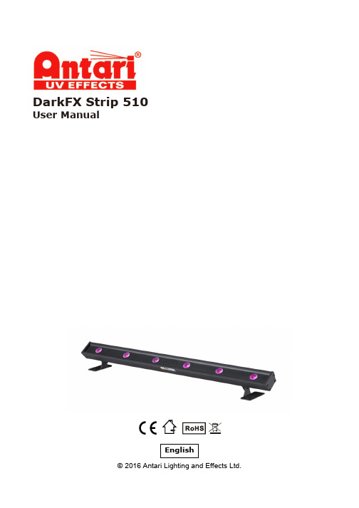
DarkFX Strip 510
User Manual
English © 2016 Antari Lighting and Effects Ltd.
User Manual – English
Safety Information
Please read the following safety information carefully before operating the fixture. Information includes important safety information about installation, usage, and maintenance. Pay attention to all warning labels and instructions in this manual and printed on the fixture.
abb工业机器人协同动作应用手册

Robotics Products Se-721 68 Västerås
瑞典
目表
目表
手册概述 ............................................................................................................................................. 7 产品文档,IRC5 ................................................................................................................................. 9 安全 .................................................................................................................................................... 11
应用手册 MultiMove
Trace back information: Workspace R15-2 version a20 Checked in 2015-10-22 Skribenta version 4.6.176
应用手册 MultiMove
RobotWare 6.02 文档编号: 3HAC050961-010
3.2.1 Controller参数域集合 ................................................................................ 30 3.2.2 Motion参数域集合 .................................................................................... 32 3.2.3 I/O参数域集合 ......................................................................................... 33 3.3 配置示例 .......................................................................................................... 34 3.3.1 “UnsyncArc”的配置示例 ............................................................................ 34 3.3.2 “SyncArc”的配置示例 ............................................................................... 36 3.3.3 输入/输出配置示例 ................................................................................... 38
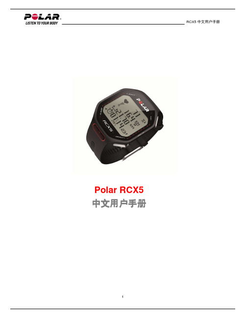
RCX5_sim
2
RCX5 中文用户手册
5
6 6 6
8 8 8 8 8
10 10 10 10 10 11 11 11
13 13 13 14 14 16 16 16 17 17 17 17 17 18 18 18 18 20 21
13. 重要数据 产品保养 服务
更换电池 自行更换电池
RCX5 的电池寿命 3
RCX5 中文用户手册
27 27
28 28 28 29 30 31 31 32 33 33 33 34 35 35 35 35 35
37 37 37 37 38 39
41 41 41
42 42 42 42 43
44 44 45 45 47 47 48 50 50 51
网上服务 网上服务是专为你支持你的训练目的而设的。在这里,你可以
建立及把 Polar 耐力训练计划下载至你的训练心率表,及在训练时运用它们。 把你的训练档案储存,以作长期跟进之用。 在训练日志分析及跟进你的进度。 利用训练负苛特性分析训练强度及所需的恢复时间。 挑战你的朋友参与虚拟运动比赛,及与其他运动爱好者互动。 所有来自兼容传感器的数据均以 Polar 专有科技 2.4GHz W.I.N.D.科技以无线方式传输到训练心 率表。这可以减低于训练时的干扰。于游泳时,数据会以 Polar 专有科技 5kHz 科技由 Polar WearLink®+两栖心率传输器传送至训练心率表。 请于 http://register.polar.fi/登记你的 Polar 产品,使我们可以继续改善我们的产品及服务,以达 致你的要求。 你的 Polar 账户名称是你的电邮地址。相同的帐户名称及密码可以用于 Polar 产品登记、 、Polar 讨论区及登记通讯。 可选配件
德国TRAMEC五轴头应用需求表 中英文
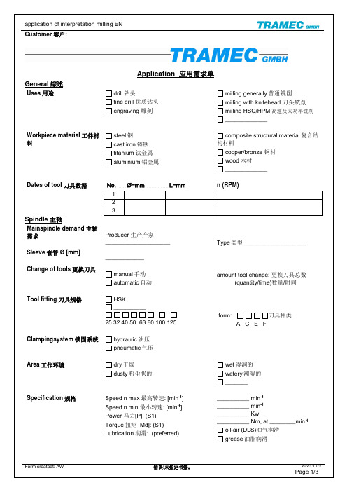
application of interpretation milling ENCustomer 客户: Form createdt: AW 错误!未指定书签。
site: 1 / 3Application 应用需求单General 综述Use s 用途drill 钻头fine drill 优质钻头 engraving 雕刻milling generally 普通铣削milling with knifehead 刀头铣削milling HSC/HPM 高速及大功率铣削 _____________Workpiece material 工件材料steel 钢 cast iron 铸铁 titanium 钛金属 aluminium 铝金属composite structural material 复合结构材料cooper/bronze 铜材 wood 木材_____________Dates of tool 刀具数据 No. Ø=mm L=mm n (RPM)1 2 3Spindle 主轴Mainspindle demand 主轴需求Sleeve 套管 Ø [mm]Change of tools 更换刀具Producer 生产产家________________________________manual 手动 automatic 自动Type 类型 ___________________amount tool change: 更换刀具总数 (quantity/time)数量/时间Tool fitting 刀具规格HSK__________25 32 40 50 63 80 100 125form: 刀具种类 A C E F Clampingsystem 锁固系统 hydraulic 油压 pneumatic 气压Area 工作环境dry 干燥 dusty 粉尘状的wet 湿润的 watery 潮湿的 _______Specification 规格 Speed n max 最高转速: [min -1] Speed n min.最小转速: [min -1] Power 马力[P]: (S1)Torque 扭矩 [Md]: (S1) Lubrication 润滑: (preferred)__________ min -1__________ min -1__________ Kw__________ Nm, at ________min -1oil-air (DLS)油气润滑 grease 油脂润滑Processcooling冷却方式Inside内部Outside外部 coolant through the spindle _______ bar pressure冷却液通过主轴的压力为_______barcompressed air through the spindle压缩空气通过主轴 lubrication through the spindle润滑剂通过主轴changeover转换lubricant coolant 润滑油冷冻剂Millunit铣轴单元C-axis alingment C轴安装方式 horizontal水平的 RAM – dimension尺寸 (Z – axis)vertical 垂直的 inside内部 ______ mm X ______ mmor inside或者内部Ø ______ mmoutside外部 ______ mm X ______ mmDrive驱动 worm gear涡轮 travel speed转动速度 [°/s] ________direct drive直接驱动 (Torque扭矩) pivotangle摆角[°] C ________endless不停的clamping锁固方式 pivotangle摆角[°] A _________simultaneous torque连续扭矩≥ ______ NmPeriphery配套设备 frequency inverter变频器 ____ (preferred更好的) to be supplied 附带的throttle节流阀 ____________ (preferred) to be suppliedchiller冷却器 ____________ (preferred) to be suppliedhydraulic unit油压单元 ____________ (preferred) to be suppliedlubricate unit润滑单元 ____________ (preferred) to be suppliedelectric connector电气接口 ____________ (preferred) to be supplied____________________________ to be supplied____________________________ to be suppliedSpecials norms/ imposts 特殊要求Documentation文件要求Data exchange数据交换________________________________________________________german德语中文____________________________2D .dwfAutocad .dxf version 版本____________Autocad .dwg version 版本____________3D step simplified3D step detail (costs according to complexity费用取决于复杂性)Page 2/3Formular erstellt: Ch. Heil 03.05.2013Application应用描述(detail description细节描述)Date时间 ________________ Signature签名 ________________联系方式:Shanghai Skybow Precision Machine Co., Ltd.Page 3/3 上海天弓精密机械有限公司Address:No.300 of Maosheng road, Dongjin Town, Songjiang District, Shanghai China 地址:上海市松江区洞泾镇茂盛路300号 Zip code:201619Phone:+86 21 33524931, 33524934 Fax :+86 21 33524932Website: Formular erstellt: Ch. Heil 03.05.2013。
火龙果软件--Trac学习手册

Trac学习手册在项目开发中,我倾向于大任务分解、小团队、迭代开发、持续交付。
在管理上,我更看重人与人的交流以及交流后的共识,提倡客户、开发人员、测试人员等面对面的交流,让代码说话。
因此,在选择项目使用的工具上,我更喜欢一些轻量级的开发、配置和管理工具。
在项目配置和管理方面,以前也用到过很多工具。
版本控制用过VSS、TeamSource、CVS和Subversion,项目管理、bug跟踪方面用过Project、CVSTrac 和Trac,当然还有最基本的Excel。
目前我做的项目基本上都是使用Trac+Subversion来构建的,为什么呢?版本控制方面,VSS是以前用的,微软的,大而笨重,TeamSource是Borland的东东,不是很流行。
剩下的就CVS和Subversion了,老实说,我用这两个东东的时间都不长,都是免费,分布式部署比较方便,都够用,真正让我确定使用SVN的是Trac。
我使用CVS完全是因为要用CVSTrac,一个轻量级的项目管理和错误跟踪工具(具体可以参见cnpack)。
直到后来,我知道了Trac,觉得这就是我需要的项目配置和管理的平台。
具体说Trac对我最有用的是Wiki、里程碑、任务管理(bug跟踪)和集成Subversion。
使用wiki我可以轻松的构建项目的网站,项目内容管理,资源链接以及信息发布等等。
里程碑使我的迭代计划更加易于管理,每个迭代(里程碑)有多少工作量,完成了多少,还剩多少,时间节点,相关的资源一目了然。
任务管理最明显的好处就是bug跟踪,还可以为每个里程碑、模块分配任务,并有多种报告可以查看,小团队管理的利器啊。
集成Subversion,可以在Trac网站中查看Subversion的资源,这样,客户和业务人员不使用Subversion也可以获取相应的资源了。
Trac和Subversion好处很多,但安装有点费劲,当然,对于熟手来说很容易。
我当时弄了好久才搞定Trac,今天早晨才使用上WebAdmin插件。
Smart 5系列监视器快速上手指南说明书

Smart 5 Monitors Quick Start GuideThe new Smart 5 Series is engineered to deliver the same professional toolset of our Ultrabright and Smart 7 series in a rugged, compact, 5-inch monitor with daylight-viewable displays and unmatched PageOS functionality.The powerful, portable, and adaptable Ultra 5 offers 3000nits of dazzling brightness, a locking power adaptor, an Ethernet port for ARRI camera control, plus a full suite of large, front-facing physical buttons for maximum control in all conditions. The Cine 5 is lightweight, compact, and offers 2000nits of daylight-busting brightness – plus a convenient joystick and back button that allows for quick adjustments while wearing gloves. The Indie 5 is the smallest and lightest monitor in the Smart 5 Series, with 1000nits of brightness, and optional camera-control functionality.Experience all your favorite PageOS 5 tools, functions, and settings pages on any of our premium 5-inch touchscreen monitors.TABLE OF CONTENTS1. ACTIVATE WARRANTY (4)2. PHYSICAL PROPERTIES (4)3. POWER AND CONNECT (8)4. PAGEOS OVERVIEW (9)• General Layout (10)• Basic Navigation (11)• Input and Output (14)• Display (14)• Controls (15)• Capture (16)• Interface (17)• User (18)• System (19)5. ADDITIONAL RESOURCES AND FCC RULES/REGULATIONS (20)ACTIVATE WARRANTYPHYSICAL PROPERTIESA: M3x0.5mm F: SDI Input/Output J: Headphone B: HDMI In G: SDI Input K: UI Lock Switch C: HDMI Out H: Power Button L: Micro USB D: ¼"-20 Mounting Points I: L-Series Battery Plate M: SD Card Slot E: 5.5mm x 2.0mm BarrelConnector (DC 10-34v)A: M3x0.5mm G: SDI Input/Output M: L-Series Battery Plate B: HDMI In H: SDI Input N: UI Lock SwitchC: HDMI Out I: Power Button O: Micro USBD: 5-Pin Locking USB J: Joy Stick P: SD Card SlotE: ¼"-20 Mounting Points K: Back ButtonF: 2-pin Locking Power Input L: HeadphoneA: Joystick G: Ethernet M: Headphone Output B: Back Button H: ¼"-20 Mounting Points N: UI Lock Switch C: Custom Function Buttons I: 2-pin Locking Power Input O: Micro USBD: 5-Pin Locking USB J: SDI Input/Output P: SD Card SlotE: HDMI Input K: SDI InputF: HDMI Output L: Power ButtonA: Joy Stick G: EthernetM: Headphone Input B: Back ButtonH: ¼"-20 Mounting Points N: SD Card Slot C: Custom Function Button I: 2-pin Locking Power Input O: Micro USB D: 5-Pin Locking USB J: SDI Input/Output P: UI Lock SwitchE: HDMI Input K: SDI Input Q: Pogo Interface for CS Micro Pro Battery PlatesF: HDMI OutputL: Power ButtonA: Joy Stick G: EthernetM: Headphone Input B: Back ButtonH: ¼"-20 Mounting Points N: SD Card Slot C: Custom Function Button I: 2-pin Locking Power Input O: Micro USB D: 5-Pin Locking USB J: SDI Input/Output P: UI Lock SwitchE: HDMI Input K: SDI Input Q: Pogo Interface for CS Micro Pro Battery PlatesF: HDMI OutputL: Power ButtonPOWER AND CONNECTPOWER1. Connect power to the monitor using a L-Series style battery or an alternative power source.2. Press the power button. INPUT/OUTPUT• Video signals via HDMI up to 4Kp30• Video signals via SDI up to 1080p60MOUNTING OPTIONS¼"-20 MOUNTING POINTSCine 5/Indie 5: 6x ¼"-20 mounting points secure the monitor to a camera or rig (left side, right side, and bottom).Ultra 5: 4x ¼"-20 secure the monitor to a camera or rig (left side, right side, and bottom).Ultra 5 TX/RX: 3x ¼"-20 mounting points secure the monitor to a camera or rig (left side, right side, and bottom).PAGEOS 4 OVERVIEWThe PageOS 4 interface allows users to configure and assign specific image analyzing tools and/ or features to up to eight customizable pages. Users can access those tools by navigating to the corresponding page on the monitor, instead of enabling or disabling features individually.General LayoutPages ViewThe ‘Pages View’ offers a zoomed-out perspective of all configured pages, allowing organization and naming to ensure the most efficient overall setup.SettingsAdjust a wide range of global monitor settings.DashboardThe Dashboard provides access to the most commonly-used settings such as Input, Volume and Backlight. The Dashboard can be disabled via Full Settings > Dashboard.Basic NavigationTouch ScreenPageOS has an easy-to-navigate touchscreen that works just like your smartphone.• Pinch to zoom• Swipe left and right between custom pages• Slide your finger down for a view of all your preset pages• Swipe all the way left to access your deep settings menu (Calibration, Profiles, etc)Adding New PagesTo create a new page from either a fresh workspace, a template, or a specific utility, navigate to the right-hand side of the Pages View.Add New Tool to a PageTap your screen while on any page to reveal the toolbar. Press the plus sign that appears on the left side of the page. Select the tool you want to be added to that page.Activating ToolsTap your screen while on any page to reveal the toolbar. Then select the tool you want to activate. To adjust the custom settings of that tool press the arrow that appears next to the name of the tool. Joystick / ButtonSome Smart 5 models are equipped with a Joystick and Buttons which can also be used for navigation if desired.EL ZoneEL Zone is a stop-based exposure map tool—developed in collaboration with legendary cinematographer Ed Lachman, ASC that works like a virtual spot meter, replacing IRE exposure values with stops. Sensor data from the camera provides a reference point, and a false color represents each stop above and below 18% gray, allowing for easier, more intuitive on-set communication.EL Zone is only possible to use if you are feeding your SmallHD monitor a Log signal. It doesn’t work if you are inputting a signal with a LUT enabled.To enable EL Zone, make sure you create a color pipe in your monitor's settings menu. You will need to send the monitor a LOG signal and select the log signal that you will be sending it. NOTE: Make sure you select "Do Not Convert" in the Color pipe options.Settings: Input and OutputInput ConfigSelect an input to display its image -- configure a source to unlock log conversions into HDR and SDR color spaces.Color PipeFollow the Wizard instructions to assign and configure color space and curve transformations, to enable HDR and SDR from incoming log-based sources.Settings: DisplayBacklightSelect a backlight level that suits your viewing environment to maximize contrast and viewability. CalibrationCalibration ensures chrominance and luminance accuracy that can be relied upon for critical color decisions.AppearanceApply sharpening to the video data, if desiredSettings: ControlsVolumeAdjust the audio output level for the headphone jack and/or monitor speaker.Image RotateImage Rotate options enable upside-down mounting - or enable Mirroring for when the monitor must face the subject.InterlaceThese options control how interlaced footage is displayed.Settings: CaptureImage CaptureConfigure the Image Capture tool to help facilitate shot matching or for automatic thumbnail creation upon pressing Record. (Note: SD card must be inserted into the monitor to perform an image capture). Image GalleryBrowse the Image Gallery to review the images on your removable media.Settings: InterfacePixel ZoomConfigure the default zoom levels for Pixel Zoom to ‘punch in’ to a desired amount when spot checking a particular shot.Status DisplayEnable and configure the Status Display to get info on various monitoring-related data such as battery life and frames per second.UI LockOnce enabled, pressing and holding on the touchscreen for five seconds will lock the UI. Repeating the process will unlock the UI.LanguageChange the language of the internal menu system.Settings: UserBackdropEnable a customizable backdrop for when the monitor is not displaying a signal.PowerPower-related options such as auto recovery.Date TimeSetting the correct Date & Time will ensure that captured images get an accurate timestamp. Monitor IDSet a custom name for your monitor, to make it more easily recognizable.ProfilesSave or load the entire monitor’s configuration to an SD card, great for keeping consistent settings across several monitors.Settings: SystemFirmwareFirmware can be updated by inserting an SD card with a compatible update file. For the latest firmware download visit: /softwareFactory ResetReset the monitor settings to their original factory settings, with the option to clear registration and calibration.LicensesFollow the on-screen prompts to install your purchased license keys (for example, Control for KOMODO).ComplianceCE, FCC, UKCAADDITIONAL RESOURCES AND FCC RULES/REGULATIONS。
Cardiris 5产品入门指南说明书

Getting Started GuideProduct versionsThe Cardiris 5 is a standalone software product that can be used with any twain based scanner to process the business card information. It is also bundled in the IRIScan Anywhere product. There are two versions of the software.Cardiris Pro 5Cardiris Corporate for Microsoft Dynamics CRM 5Both operate in the same fundamental way. In this guide we will cover the functions of the Pro 5 and then the differences in the CRM 5.Cardiris Pro 5Scanner setupThe product can be used with any of the business card capable scanners from our previous or current products to process individual card images. It can also process images of multiple cards in the same image and extract the individual images for processing. You can also open prescanned images for processing by clicking the down arrow next to scan and change it to Load.In the Cardiris software Go to the Settings menu > Scanner and select the scanner you are usingIf you select an Iris scanner and click next you will get a window similar to the one pictured below depending on the scanner model selected.Set your scan options, click on OK and then click on the scan button in Cardiris.If you are using a non-IRIS scanner then highlight on the “Other” choice and click on Next >Pick the Scanner Source then the scanner model and configure as pictured making sure the format is set to the appropriate choice. If your scanner is not listed find the closet match or use <Twain> <Other Models>.Letter is used when scanning one image of multiple cardsas will be discussed below. Typically used for flatbed scanning.If your scanner has a business card capable automatic document feeder then check the ADF box.If it can scan the front and back in one pass then check the Duplex scanning box. This will place both images in the contact field in Cardiris.Flatbed scanningYou can place up to 10 cards on the glass of the scanner. You want there to be a gap around all edges of the card keeping it away from the edge of the scanner bezel. You also want a dark background so the software can separate the individual card images from the larger image. A black or dark sheet of paper placed behind the cards works best. Scan at 400 DPI in color.You could also leave the lid to the scanner open but on some scanners you risk light leaking in on an edge of the image creating a very subtle white line making it impossible for the software to extract the individual card images.For very dark cards you would do the opposite and just close the lid to the scanner to create a white background. It is useful then to separate the cards into dark and light for this kind of processing.You can also scan outside of the software and save the scans as image files which can then be processed in the software. Open Cardiris and go to File > Load Card images and navigate to where the images are stored and select one or more of the images. Go to the Process menu > Extract images to separate the individual images from the larger image.Program UsageThe workflow is to; 1. Scan | 2. Recognize & verify | 3. ExportPrior to Exporting double click on the desired card to enter the contact view to verify the information is correct and set a card status for easy segregation of the Cards. You can also set Categories or include custom fields.Toolbars functionsIn the Contact view you can select the Front | Back | Picture tabs to scan/view secondary images for the contact.Information that is on the Card that does not have a location is put into the Extra tab on the lower left. A notes tab is provided to allow additional information to be typed in.Note the N I V buttons for categorizing the cards as New, Indexed or Verified.Custom FieldsCategories, click on Edit to add or removeImport, Export & Synchronize.Import Commonly used to import data from another Cardiris database or program. This is useful to consolidate information and/or export elsewhere.ExportThe most used items are Microsoft Excel, Microsoft Outlook, Text (*.csv) and vCard (*.vcf)Note the Configure button on the lower left of the screen. This is important and allows you to configure options relevant to the output format you have choosen.In Outlook you need to choose the contacts folder where you want the information sent and whether to include the card image.For vCard you have the option to create on file with all the contacts or multiple files with a single contact.Note also the Export all Card check boxThis is an easy way to bring in information from a previous Cardiris version.You can also import individual vCards files or vCards files that contain multiple contacts.SynchronizeThe synchronize exchanges information between the selected program and Cardiris.Organizing CardsOnce you have scanned in a batch of cards and exported the information and then scan in the new a problem arises of how to separate the two batches. Within the Card view are three buttons for New, Indexed, and Verified. These are used to solve this issue with all new cards automatically being assigned and color coded new.You could also use the Advanced Search by going to the Card menu > Advanced Search and specifying a scan or modification date. Only those cards in that range will be displayed and exported.You could also simply archive to vCard and delete the cards to make room for the new batch.If Outlook is selected all the contact in Outlook will be brought into Cardiris and all the contact in Cardiris will be sent to Outlook.Usually this is not what you want to do unless you are looking to consolidate and reprocess the information elsewhere.The fundamental difference in this version is the Microsoft Dynamics CRM export option.Highlight the Microsoft Dynamics CRM and click on configure.You will need to fill in the configuration details for your CRM installation.This information can be obtained from your CRM adminstrator.Pictured is a sample configuration. Click next and it will connect to your server. For Remote servers allow time to establish communication.Next you will get the field mapping screen where the contacts in Cardiris are matched to the fields available on the server.Click Ok and you will return to the Cardiris screen where you can click on export.You will then get the find duplicates window. Click on the Find Duplicates button and it will show any possible duplicates.If none click on OK and the export will proceed.。
Haefely AXOS5 可编程仿真系统说明书

Haefely is a subsidiaryof Hubbell Incorporated.a brand ofcompact immunity test system1981COMPACT IMMUNITY TEST SYSTEMThe new AXOS5 compact immunity test system integrates all of the best features of our stand alone test systems into one single economic solution.It combines 5 kV Burst/EFT, Surge com-bination wave, AC/DC Dips & Interrupts, along with an integrated single-phase coupling / decoupling network into one compact test system.This allows quick and completely auto-mated testing to the most common IEC, EN, ANSI, IEEE and UL standards. AXOS5 can either be operated via front panel by large colour graphic interface or remotely from the PC.The easy to use menu together with the availability of predefined test routines for different standards makes testing easy and reliable, even for less frequently us-ers. Numerous additional functions such as external start/stop function allows easy integration of the test system also in cus-tomer specific test environments.All the test parameters can be varied in a broad range wide above the require-ments of the standards. Together with the ability of changing test parameters during test, AXOS5 is not only the ideal product for compliance and pre-compli-ance testing, it is useful for monitoring & debugging function during design phase as well.A wide range of cost-efficient and user friendly coupling / decoupling networks for power lines as well as for symmetrical and asymmetrical data- and signal lines are available as options.overviewFEATURES & BENEFITS⏹ Easy to operate with manual and au-tomated test modes, software assist-ed test preparation, pre-defined test routines and visual aided test setups STANDARDS⏹ IEC/EN 61000-4-4 EFT / Burst⏹ IEC/EN 61000-4-5 Surge⏹ IEC/EN 61000-4-9 Imp MagnetictecHnicaL speciFicationsGENERAL DATA Control power 85 V - 264 V 50/60 Hz Dimensions (W x H x D)19“ / 4U(45 x 18 x 49 cm)User test storage unlimited Weight 30 kgRemote interface Ethernet, RJ45USBfor USB memory stick Display7“ / 800x480 / 24 bit AUX. interfaceD-sub 37p for external External trigger input5 V T TLSynch input BNC, 10 V – 264 V AC T rigger output 5 V T TL External start / stop input5 V T TL, starts / stops predefined test sequence EUT failed input 5 V T TLAnalog output 0 – 10 V, for use with external options Warning lamp output2 x 24 V / 1 A DCSafety circuitstops the test when unlockedaxial output Polaritypos / neg / alternate Burst duration 10 us – 1 s Output impedance 50 Ohms Burst period 1 ms – 10 s Rise time 5 ns ±30%T est time 1 s– 999 minutes Impulse duration50 ns ±30% at 50 Ohm 50 ns –15 +100 ns at 1000 OhmT riggerautomatic, manual,external trigger input Burst modenormal, continuous, real, randomIntegrated single phase coupling / decoupling network264 V AC / 16 A 220 V DC / 10 AICE / EN 61000-4-5 EDITION 2 SURGE COMBINATION WAVEOutput voltage0.2 – 5.0 kV ±10%Output current0.1 – 2.5 kA ±10% Voltage rise time 1.2 us ±30%Current rise time8 us ±20% Voltage duration50 us ±20%Current duration20 us ±20%Polarity pos / neg / alternate Integrated singlephase CDN 264 V AC / 16 A 220 V DC / 10 AOutput impedance 2 Ohmsscope oF suppLy – options & accessoriesSCOPE OF SUPPLY AXOS52490400 Qty. 1 Immunity Test System AXOS5Qty. 1 Mains Cable 10 AQty. 1 EUT Power Cable 16 AQty. 1 EUT Power AdapterQty. 1 User ManualOPTIONS AND ACCESSORIESFP-COMB 32 3-Phase / 32 A Power Line CDN Surge & EFT 2490430 FP-EFT 100 M2 3-Phase / 100 A Power Line CDN EFT 2495860 IP4A Capacitive coupling clamp for EFT 2491300 FP-SURGE 100 M2 3-Phase / 100 A Power Line CDN SURGE 2490181PCD 121 Symmetrical Data & Control Line Coupler 2498010 PCD 126 A Asymmetrical Data & Control Line Coupler 2498030 DEC 5 Symmetrical Data & Control Line Decoupler 2490141 DEC 6 Symmetrical Data & Control Line Decoupler 2490151 DEC 7 Asymmetrical Data & Control Line Decoupler 2490161 DIP 116 Automatic Dips Transformer 16 A 40/70/80% 2490410 MSURGE Magnetic Field Test IEC / EN 61000-4-9 2495591VTM 15000 Isolation Test 1.2/50 us up to 10 kV 2499960 PDP 8000 HV differential Probe 1000:1 for Surge 2499911 CP 101 Current Probe Model for Surge 2499931 ES External emergency stop Switch P12 4700751 WL External warning Lamp P12 4700750 WinFEAT’R Control, Measurement & Reporting Software 2499701 Calibration Accredited Calibration AXOS5 2490420aXos – perFection. DeLivereD.FEATURES⏹7“ / 800 x 480 / 24 bit touch-screen⏹Reduction of daily working effort dueto easy access menu structureJ a n u a r y 2012Headquarters China (Sales & Service Office) North American OfficeHaefely T est AG HAEFEL Y Representative OfficeHipotronics Inc.Birsstrasse 300 8-1-602, Fortune StreetHaefely EMC Division4052 Basel No.67, Chaoyang Road, Chaoyang District1650 Route 22SwitzerlandBeijing, China 100025Brewster, NY 10509☎ + 41 61 373 41 11 ☎ +86 10 8578 8099 ☎ +1 845 279 3644 + 41 61 373 49 12+86 10 8578 9908 +1 845 279 2467*************************************.cn****************************。
Sartorius 萨托利斯 Sartocheck 5 Plus 滤器完整性测试仪 产品手册说明书

Product InformationThe Sartocheck® 5 Plus represents the ideal intersection point of today’s most relevant industry requirements for filter integrity testing within demanding GMP environments. A combination of a unique approach to Quality Risk Management (QRM) as well as optimal data integrity, intuitive usability, and minimized risk factors for Health, Safety, and Environment (HSE) set a new standard for filter integrity test devices.Sartocheck® 5 Plus Filter TesterKeeps Your Risk Factors Under Complete ControlNew Software Release Q1 2023 - Version 2.2.1Data Integrity-Custom Linux-based OS with SSB custom architecture-Audit trail with time zone-synchronized (NTP) events-Write-protected and constantly monitored root file system-Encrypted double data backup | redundant data storage-4 eyes principle | electronic signatures-Comprehensive and flexible role management-Locking out user after X number of unsuccessfullogin attempts-Serial number of the device in every audit trail entry-Easy to read audit trail on the screen-Harmonized time representations-A major update of the root file system of the SC5 inthe Q2 2022 release will further strengthen the datasecurity aspects of the software-Mandatory “Why” comment when modifying programparameters (Q2 2022)-Blocking of abusive test attempts (Q2 2022)Request the Data Integrity statement for more details.CCS, HSE | OSH-Splash-proof (IP64)-Ex-proof (ATEX IECEx & FM certified)-Safe testing and re-testing of alcohol-wetted filters-Continuous and clear visualization of pressure status-Resistant to all current cleaning agents-H2O2-vapor-resistant (VHP)-PFA tubings (FDA 21 CFR 177 and USP Class VIcompliant)-Optional kit for automated cleaning of the pneumaticswith up to 0.5 M NaOH at 50 °C, available in Q3 2022(requires at least software version 2.0.0). See theC ontamination Control Strategy documentationfor additional information-Optional accessory kit for backflow protection(26787---AK---EV)Quality Risk Management-Automatic detection of incorrect test setups-Program-specific min. and max. values for volumedetermination-Program-specific min. diffusion | intrusion values-Program-specific min. flow at pressure end duringa bubble point test-Automatic detection of abnormal test conditions-Detection of abnormal pressure increase-Detection of environmental temperature outsideprerequisite conditions and temperature changes(roadmap – requires sensor)-Detection of unstable test values(roadmap – pat. pending)-Self-test at booting and before each test-Comprehensive Failure Mode Effects Analysis (FMEA),including instructions for setting program-specificQRM values to avoid false passed and false failedtest results-Calculation tool for the impact of unlikely calibrationoffsetsUsability-Intuitive iF-design-rewarded Human Machine Interface(HMI)-12.1" bright touchscreen with a ± 88° viewing angle-Large digital keypad - no need for a pen –compatible with glove use-10 system languages-LDAP: log on with network user credentials-Automatic test time for faster testing-Data transfer-Automation by OPC UA or Modbus TCP-Additional keyboards (Korean and Cyrillic)-LDAP group-based role management-Filtering of displayed audit trail events-Audit trail export in a digitally signed write-protected PDF-Remote administration via OPC UA-Memory management (21CFR Part 11)-Printing via printer server-DNS name support-Scheduled export of the audit trail in PDF format-Improved program parameters for large crossflow system(TFF) systemsSurpass the Requirements of QRMThe regulatory focus on QRM (cf. ICHQ9 and the newAnnex 1 written by EMA in cooperation with the US-FDA,WHO, and PICs) also applies to filter integrity testing,as a fundamental element of sterility assurance.The Sartocheck® 5 Plus Filter Tester uses program-specificparameters allowing the automatic identification oftesting anomalies before or during the test. This preventstime-consuming, costly variations, potential drug recalls,and 483 warning letters.Experience the Comfort of Intuitive UsabilityAn optimal user experience speeds up process workflowsdue to intuitive guidance and ease of use. The high-qualitytouchscreen of the Sartocheck® 5 Plus Filter Testerprovides a unique viewing angle, an intuitive user interface,a logical menu structure, and simple data entry options.This allows straightforward programming of tests andQRM enhancement features, as well as error-free operationin GMP production environments.Reach the Ultimate Level of Data IntegrityFilter integrity test values are part of the batch protocoland are used to justify the drug release. Long-term reliabledata is crucial to avoid quality deviations and potential 483warning letters.The integrity and security of filter integrity test data mustnot be seen only as an IT problem, but also as a potentialglobal business risk. Low standards of data integrity andsecurity may not only jeopardize the activities of the drugmanufacturing company, but more critically, endanger thehealth of patients.Discover the Simplicity of HSEIntegrity testing often involves the use of chemicals andhazardous materials, e.g., alcohol. The Sartocheck® 5 Plusis certified for use in explosion-hazardous areas (ATEX)and is compatible with all current cleaning agentsand VHP. This ensures maximum safety for operatorsand manufacturing facilities.Pneumatics Max. inlet pressure 8,000 mbar | 116 psiOverpressure protection Max. inlet pressure + 4,000 mbar Min. inlet pressure 4,000 mbar | 58 psiInternal reference volume1,023 mL conforming to Pressure Equipment Directive 2014/68/EU max. Pressure = 12 bar pressurecertificateMeasuring Accuracies Measured pressure± 0.1% full scale(± 7.2 mbar | ± 0.104 psi)Measured pressure drop0.2% of the measured value before rounding Volume determination± 4%Diffusion ± 5% or 0.05 mL/min, whichever is higher Intrusion ± 5% or 0.05 mL/min, whichever is higherstarting pressure to one pressure step above the min. bubble pointDimensions, Weight, and Noise Dimensions (W × D × H)348 × 379 × 286 mm Weight16.8 kg Weight of the packaging 2.2 kg Cargo | gross weight 20.6 kg Cargo volume 95,304 cm 3Cargo dimensions 570 × 440 × 380 mmMax. noise at 1 m during depressurization with venting tubings68 dB(A) at 6,600 mbar (95.7 psi)51 dB(A) at 3,000 mbar (47.9 psi)Manufacturing SiteDesigned, developed, and manufactured in Germany Otto-Brenner Strasse 20Goettingen, GermanyEnd-user TrainingThe Sartocheck® comes with end-user training.Technical DataTest Methods DiffusionBubble point (detection by over proportionality)Combined diffusion and bubble point Water intrusion test Pressure drop | leak testMeasuring Ranges Diffusion andintrusion test pressure 50.0 – 6,600.0 mbar | 0.725 – 95.725 psi Programmable max. diffusion flow 0.011 – 4,800.000 mL/min.Programmable max. intrusion water flow0.006 mL/min. – 60.000 mL/min.Max measurable | displayable diffusion flow24,000.00 mL/min. (5 times the max. programmable value)Max. measurable | displayable intrusion water flow 300.00 mL/min. (5 times the max.programmable value)Programmable min.bubble point250.0 – 6,550.0 mbar | 3.626 – 95.000 psiProgrammable pressure drop (not higher than the test pressure)0.5 – 6,600.0 mbar | 0.007 – 95.725psiSample net volume with volume measurement-with int. reference vessel-with ext. reference vessel 14 L 150 L Max. sample net volume for pressure drop test1,000 LPower Supply Power requirements 100 – 240 V AC at 50 | 60 Hz Max. power input 74 W Average power usage 66 W Power consumption in standby mode14.8 WA country-specific cable is delivered with each device.Internal batteryThe Sartocheck® 5 is equipped with an internal battery. This battery (CR2032) contains less than 0.3 g lithium.Materials of Construction and RoughnessAll materials used for the external surfaces and the fluid paths are animal free.External Surfaces-Ra 1.6 μm or better -Stainless steel 304L-Heat strengthened glass (see “Screen and Protective Glass”) -Plastic polymer (Edistir® polystyrene PBBE free) painted with chemical resistant Alexit finishing coat B412-Aluminum painted with chemical resistant Alexit finishing coat B412 -Rubber feet: Taber H-18 abrasion resistant (ASTM-501C)Pneumatic Fluid Path of the Sartocheck® 5 Plus-Ra 1.6 μm or better-Aluminum (inlet valve block, no potential product contact) -Stainless steel 304L (process valve block) -Stainless steel 316L (connectors)-EPDM (connector gaskets), FDA 21 CFR 177 and USP Class VI (A) -PFA tubings, FDA 21 CFR 177 and USP Class VI (A)-PTFE (valve block membrane FDA 21 CFR 177 and USP Class VI (A)Pneumatic Fluid Path of the Accessory Kit for External Venting -Ra 1.6 μm or better-Stainless steel 304L (valves)-Stainless steel 316L (connectors)-EPDM (connector gaskets) FDA 21 CFR 177 and USP Class VI (A)External Tubings (Inlet and Test Tubing)-PFA tubings, FDA 21 CFR 177 and USP Class VI (A) -Stainless steel 316L (connectors)-EPDM (connector gaskets) FDA 21 CFR 177 and USP Class VI (A) -Sintered Polyethylene (inlet filter) -Polypropylene (inlet filter housing)-Stainless steel 316L Parker nippleScreen and Protective Glass Size12.1" (Format 16:10;262.6 × 164.7 mm | 10.34 × 6.48 inch)Type TFT LED-Backlit color Resolution 1,280 × 800 pixels Luminosity400 CD/m 2Viewing angle vertical and horizontal ± 88° (total 176°)Shock resistance Thermally toughened glassDIN EN 12150-1; IEC 60068-2-75AntiglareLS Touch Gloss 85 ± 10 | 60° on front sideConnectors and PortsAll connectors on the device are specifically defined in order to avoid mix up between different connections. E.g., the test tubing can only be connected to the outlet of the device.Pneumatic Connectors Inlet tubing towards pressurized lineParker nipple (Parker reference 26SFAW13MXN)Inlet tubing towards device Staubli RBE03 female Test tubing towards sample to be testedStaubli RBE03 femalePneumatic TubingsAll pneumatic tubings have been leak-tested at the end of manufacturing.Use only original test tubings of original length with original connectors to avoid any mix-up.Communication Ports-Industrial automation for OPC UA and Modbus TCP -Ethernet RJ45 for networking and data transfer-USB (4 ports) for software upgrades, barcode reader, and USB printerOperating Conditions Environmental temperature and humidity according to IEC 61010-10 °C to 40 °C (32 – 104 °F)From 0 °C to 31 °C 80% RH From 31 °C to 40 °C linearly decreasing to 50% RHAltitude100 m below sea level to 3000 m above sea levelIngress protection rating of the device as per EN 60529 |IEC 60529IP64 under normal conditions IP4X for use in potentially explosive atmospheres Ingress protection of the Accessory Kit for External Venting as per EN 60529 |IEC 60529IP65Explosion-prone areas (device only)Zone 2, Groupe II-B (IECEx, ATEX) |Class 1 Zone 2 Group II-B (USA)Explosion-prone areas (Accessory Kit for Venting)Zone 1 Group II-B (IECEx, ATEX) |Class 1, Div. 1, Zone 1 Group II-B (USA)Connectors on the backside1 Earth5 4 × USB (e.g. printer) 2 Future environmental,6 Future extender box temperature sensor7 RJ453 External pressure sensor 8 Industrial automation4 External valves9 PowerBack cover closed1 Device cleaning 5 Ext. reference tank2 Outlet | test tubing 6 Inlet pressure, max. 8 barg,3 Sample vent 7 External valves pressure supply4 Device ventFixation of cables1234567891234567Operating System and Memory-Custom Linux Distribution made by Sartorius -Flash memory 4 GB -RAM 2 GB-Internal inaccessible SD card 8 GB-CPU MSC NanoRISC i.MX6 D 800 MHzMemory CapacityThe memory can hold approximately 21,900 test results.At a rate of 10 tests per day, 365 days per year, the memory will be full after approximately 6 years.Test Result Calculation, Evaluation, and RoundingThe test evaluation is done before the rounding, meaning that, e.g., a measured diffusion value with 16 decimals of 4.4000000000000001 mL/min. will give a failed test if the max.diffusion value is set to 4.400 mL/min. The test result rounding is done according to the tie-breaking rule called “round half to even”. This is the default rounding mode used in IEEE 754 computing functions and operators.Storage and Transportation ConditionsFrom -10 °C to +60 °C (14 – 140 °F) at 90% RH noncondensing humidity.The original cardboard box is single-use shipping only.For subsequent shipping, please use the solid transportation box 26787---ST (see accessories).Language Options -English -German -French -Spanish -Italian-Mandarin (simplified) -Portuguese (Brazilian) -Japanese -Korean-RussianCleaning and Chemical Compatibility of External Surfaces (Based on Alexit Lacquer Compatibility)Do not use any abrasive cloth.Only smooth cloths or towels are allowed.-Spor-Klenz® Ready-To-Use Cold Sterilant -3% Hydrogen Peroxide WFI Sterile Solution -Septihol® Sterile Alcohol Solution 70% IPA -Water for injection-Sodium hydroxide (NaOH) 10% -Hydrochloric acid (HCL) 20% -Sulfuric acid (H2SO4) 20% -Acetic acid 10% -Ammoniac 10%-Quaternary ammonium compounds 0.2%-Cleansinald (Quaternary ammoniums blended with alkyl amines) -Bacterianos (Glutaraldehyde 0.5 mg/g and didecyldimethyl-ammonium chloride 1.2 mg/g; pH 3 – 5, contact time > 15 min.) -Aniospray (Ethanol 226 mg/g, Chlorure de didécyldiméthyl-ammonium 0.53 mg/g, chlorhydrate de polyhexaméthylène biguanide 0.64 mg/g contact time > 15 min.) -Amphospray (Ethanol 327.4 mg/g,N-(3-aminopropyl)-Ndodé-cylpropane- 1,3-diamine 0.33 mg/g), chlorure de didécyldiméthylammonium 1.09 mg/g),chlorhydrate de polyhexaméthylène biguanide 0.96 mg/g) -Formaldehyde 37%-Sodium hypochlorite 6%-Ethanol (60%, 70%, and pure) -Acetone (pure)-Ethyl acetate (pure) -Minncare Cold Sterilant-Vaporized Hydrogen Peroxide (VHP) at 1400 ppmCleaning of Internal PneumaticsUse only the original Accessory Kit for Cleaning (available Q3 2022)Warning!Inflammable or explosion-prone liquids must not be used for internal cleaning because the Accessory Kit for Cleaning is not compliant to hazardous areas or liquids.Use the following cleaning agents:-Sodium hydroxide up to 0.5 M at 25 °C (77 °F) -Citric acid 10% at 25 °C (77°F)-Sodium hypochlorite 10% at 25 °C (77 °F)-3% Hydrogen Peroxide at 25 °C (77 °F)Sartocheck® 5 and 5 Plus Filter Tester ComparisonFeatureSartocheck® 5Sartocheck® 5 Plus QRM-related program parameters No Yes Automation (OPC UA and Modbus TCP)No Yes Data integrityIdentical Identical HSE – ATEX | IECEx | FM Identical Identical Usability Identical Identical Accuracy Identical Identical CleanabilityIdenticalIdenticalAccessory kits(External Venting Kit and Cleaning Kit)Compatible(cleaning kit available in Q3 2022)Compatible(cleaning kit available in Q3 2022)Included software upgradesSelected upgrades are included until the software release mid of 2024Yes – A ll upgrades until the software release mid of 2024Ordering InformationSartocheck® Filter TesterDescription Article No. Sartocheck® 5 Filter Tester26787---FTEquipment included in 26787---FT Sartocheck® 5 Filter TesterInlet tubing for compressed gas 2m (26787---IT) Test tubing 2 m (26787---TT---02)Test certificateCalibration certificateInstallation and operating instructionsPower cord (region-specific)Screw driver (T20 × 100) for fixation of cables Networking cable (RJ45)Printer cable (USB)Accessories and Spare PartsDescription Article No.USB printer (without paper)YDP30Archivable paper 90 m and ink ribbon69Y03285Archivable self-adhesive paper 90 m and inkribbon69Y03286Thermal paper 5 rolls of 24 m69Y03287Self-adhesive thermal paper 5 rollsof 13 m69Y03288Inlet tubing for compressed gas 2 m26787---ITTest tubing 2 m26787---TT---02Test tubing 5 m26787---TT---05Test tubing 15 m26787---TT---15Test tubing for external venting26787---TT-AKEVComplete tubing-cable wrap for AKEV 2 m26787---02-AKEVComplete tubing-cable wrap for AKEV 5 m26787---05-AKEVAccessory Kit for External Venting26787---AK---EV(max. 10 accessorykits per device due tocalibration data)Tubing for “device vent”26787---VT---DETubing for “sample vent”26787---VT---SAAccessory kit for cleaning of the pneumatics*Germany (German manual)UK, India & US | Canada (English manual)France (French manual)Italy (Italian manual)Spain & Argentina (Spanish manual)Portugal & Brazil (Portuguese manual)China (Chinese manual)Japan (Japanese manual)Korea (Korean manual)Russia (Russian manual)Switzerland, Belgium & Canada(English, German, French & Italian manuals)South Africa , Australia | New Zealand,Israel and Denmark (English manual)26787---AKDE-CL26787---AKEN-CL26787---AKFR-CL26787---AKIT-CL26787---AKES-CL26787---AKPT-CL26787---AKCN-CL26787---AKJP-CL26787---AKKR-CL26787---AKRU-CL26787---AKVA-CL26787---AKVB-CL* For more details, please refer to the Contamination Control Strategy (CCS) datasheet.Description Article No.10 L pressure vessel including safety valveand manometer, certified for EU26787---AKPV-EUAdditional waste vessel for the accessory kitfor cleaning26787---AKWV-CLBarcode Scanner (None ATEX)26787---BSExternal reference volume26787---ERAdditional tubing for the externalreference volume26787---TE—RVSolid transportation box for theSartocheck® 5 | 5 Plus26787---STMidisart® Test Manifold for parallelbubble point1Z-LB-0002Triclamp 25 mm – Staubli nipple RBE03 open7ZML--0009Triclamp 25 mm – Staubli nipple RBE03closed7ZML--0015RBE03 openServicesDescription Article No.Validation package forSartocheck® 5 | 5 Plus26787---V3---FTSartocheck® 5 | 5 Plus installation S872QINSTSartocheck® 5 | 5 Plus installation pack(incl. travel exp.)S872QINSTPValve Kit installation S873IINSTValve Kit installation pack (incl. travel exp.)S873IINSTPSartocheck® 5 | 5 Plus IQ | OQ S872QIQOQSartocheck® 5 | 5 Plus IQ | OQservice pack (incl. travel exp.)S872QIQOQPValve Kit IQ | OQ S873IIQOQValve Kit IQ | OQ service pack (incl. travel exp.)S873IIQOQPService level agreement Advanced S872QSLAAService level agreement Comprehensive S872QSLACService level agreement Essential S872QSLAE Sartocheck® Plus Filter TesterDescription Article No.Sartocheck® 5 Plus Filter Tester26787---FT---PEquipment included in 26787---FT---PSartocheck® 5 Plus Filter TesterInlet tubing for compressed gas 2 m (26787---IT)Test tubing 2 m (26787---TT---02)Test certificateCalibration certificateInstallation and operating instructionsRisk assessment for integrity testing | FMEA (PDF)Power cord (region-specific)Screw driver (T20 × 100) for fixation of cablesNetworking cable (RJ45)Printer cable (USB)GermanySartorius Stedim Biotech GmbH August-Spindler-Strasse 11 37079 GoettingenPhone +49 551 308 0USASartorius Stedim North America Inc. 565 Johnson Avenue Bohemia, NY 11716Toll-Free +1 800 368 7178F or further contacts, visitSpecifications subject to change without notice.©2023 Copyright Sartorius Stedim Biotech GmbH, August-Spindler-Strasse 11, 37079 Goettingen, Germany Publication No. SPI2020-e。
Silicon Labs Simplicity Studio 5 用户指南说明书

Tech Talks LIVE Schedule –Presentation will begin shortlyFind Past Recorded Sessions at: https:///support/trainingFill out the survey for a chance to wina BG22Thunderboard!TopicDateBuilding a Proper Mesh Test Environment: How This Was Solved in Boston Thursday, July 2Come to your Senses with our Magnetic Sensor Thursday, July 9Exploring features of the BLE Security Manager Thursday, July 23New Bluetooth Mesh Light & Sensor Models Thursday, July 30Simplicity Studio v5 IntroductionThursday, August 6Long Range Connectivity using Proprietary RF Solution Thursday, August 13Wake Bluetooth from Deep Sleep using an RF SignalThursday, August 20Silicon Labs LIVE:Wireless Connectivity Tech Talks Summer SeriesWELCOMESilicon Labs LIVE:Wireless Connectivity Tech TalksSummer SeriesIntroduction to Simplicity Studio 5August 6th, 2020https:///products/development-tools/software/simplicity-studio/simplicity-studio-5What is Simplicity Studio 5?§Free Eclipse Based Development Environment§Designed to support Silicon Labs IoTPortfolio§Provides Access to Target Device-SpecifiedWeb & SDK Resources§Software & Hardware Configuration Tools§Integrated Development Environment (IDE)§Eclipse based, C/C++ IDE§GNU ARM Toolchain§Advanced Value Add Tools§Network Analysis, Code Correlated EnergyProfiling, Configuration Tools, etc.The Data Driving Simplicity Studio 5?Simplicity StudioGecko SDK Dev Guides, TutorialsAPI RMsRef Manuals,Datasheets, ErrataStacks, Gecko Platform,Examples, Demos,metadataHardware KitBoard IDSimplicity Studio 5 -LauncherOn the Welcome PageYou Can•Select Target Device •Start a New Project •Access Support Resources and EducationalPressing ‘Welcome’ onthe tool bar will return to Welcome page at any time.1. Welcome & Target SelectionThis is a “get started” section to help with device or board selection12342. Debug Adapters Area shows connected debug adapters including Silicon Lab kits, Segger, J-Link, etc…3. My ProductsEditable list of products you may wish to use as target devices 4. MenuMenu & Tool bar provide access to a number of functions and shortcutsLauncher Perspective -Overview1. General InformationGI card shows debugger,debugger mode, firmwareversions for adapter andsecurity, SDK12 342. Recommended QSGs Quick links to recommended quick start guides for selected product.3. BoardBoard shows which evaluation board is being used and provides easy access to its documentation.4. Target PartTarget part shows full part number and also provides easy access to its documentationLauncher Perspective –Example Projects1. Technology Filter Keyword Filter box and Technology Type check boxes let you dial into the example you are looking for.122. Resource ListResource list will show corresponding example projects that are intended for your selectedtechnology and target device.Launcher Perspective –Documentation1. Resource FilterKeyword Filter box andResource Type checkboxes let you dial into theresource you are lookingfor (Data Sheet, App Note,Errata, QSG, etc…).1232. Technology TypeTechnology check boxesnarrow your search basedon a give technology(Bluetooth, Bootloaders,Thread, Zigbee, etc…).3. ResourcesList of resources that willnarrow as you selectfilters (Data Sheet, AppNote, Errata, QSG, etc…).Launcher Perspective –Demos1. Demo FilterDemo Filter allows you to narrow your search of demos for your selected device.122. DemosList of Pre-compiled demos that are ready to be programmed into your selected device.Launcher Perspective –Compatible Tools1. Compatible ToolsLaunching pad for toolssuch as Hardware1Configurator, NetworkAnalyzer, Device Console,Energy Profiler, etc…Launcher Perspective –Tools –Pin Configuration ToolPin Configuration ToolSimplicity Studio 5 offers aPin Configuration Tool thatallows the user to easilyconfigure new peripheralsor change the propertiesof existing ones. Thegraphical view will differbased on the chip beingused.Simplicity Studio 5 -IDEIDE –Overview1. Tool Bar & MenuLaunching pad for tools 123452. Project ExplorerDirectory structure and allfiles associate with theproject.4. Editor & ConfiguratorsCode editing windows andconfigurators forproject/technologies.3. Debug AdaptersShows connecteddebuggers and EVKs5. Additional WindowsProblems, Search, CallHierarchy, ConsoleIDE –Project Configurator Overview1. Target & SDKAllows user to changedevelopment target andSDK.1232. Project DetailsCan change import mode& force generation.3. Project GeneratorsAllows user to modifywhat files are beinggenerated by projec tIDE –Project Configurator Software Components1. ComponentExpand components to see categories and sub-categories.1232. Selected Component View details of a given component. Gearindicates a configurable component. Check marks show installed components.3. Filters & KeywordsHelp you to search various component categoriesIDE –Configurators (GATT)1. GATT Configurator View, Add, Remove GATT Profiles, Services, Characteristics, and Descriptors122. GATT EditorAllows user to view & modify settings in the Profiles, Services, Characteristics and Descriptors within the GATT.IDE –Configurators (Editing the GATT)EDIT (Device Name)From GATT Configuratorclicking on an editableitem such as device namewill open up a newwindow allowing the userto see content that can beedited and several optionsfor that content that canbe selected/de-selected.Simplicity Studio 5 -MigrationSimplicity Studio -Developer Options*Bugfixes provided per software longevity commitment (https:///products/software/longevity-commitment )Developer ProjectExisting ProjectNew Project GSDK v2.7.x *Simplicity Studio 4*GSDK v3.x.x Simplicity Studio 5Secure VaultFinal Developer BinariesSS4/GSDK2.7x Continuance Option *MigrationToolkitProcess and availability varies by technologyGSDK v2.7.x *Simplicity Studio 4*SS5/GSDK3.x Upgrade OptionLIMITED SUPPORTSubject to longevity commitmentGS D K 2.x t o 3.x = M aj o r C h a n g e .Simplicity Studio –Project StructureBluetooth SDK v2.x Project StructureBluetooth SDK v3.x Project StructureProject Structure There is a change in project structure from GSDK v2.x to GSDK v3.x.It’s now much easier to see which file can be modified by the generator and it’s easier to find/identify the configuration files This is important because withGSDKv3.x many more files are generated by the addition of software components.Simplicity Studio –BGAPI CommandsBGAPI CommandBGAPI CommandsBGAPI Commandschange both theirname and theirstructure to make theerror checking andhandling of returnvalues simpler.Simplicity Studio –Changes to BGAPI CommandsChanges to BGAPI Commands With manycommands, renaming means only changing gecko_cmd_ to sl_bt_.Other functions have been renamed due to changes infunctionality, changed API class, or simply to make the functions more logical.Some API functions have been split into multiple ones while others have been merged.123Simplicity Studio 5 -DemoSimplicity Studio 5 -LinksSimplicity Studio –Useful LinksSimplicity Studio 5https:///products/development-tools/software/simplicity-studio/simplicity-studio-5 Simplicity Studio 5 User Guidehttps:///simplicity-studio-5-users-guide/latest/indexQuick Start Guide Bluetooth SDK v3.xhttps:///documents/public/quick-start-guides/qsg169-bluetooth-sdk-v3x-quick-start-guide.pdfTransitioning from Bluetooth SDK v2.x to v3.xhttps:///documents/public/application-notes/an1255-transitioning-from-bluetooth-sdk-v2-to-v3.pdfBluetooth SDK 3.0.0.2 Release Noteshttps:///documents/public/release-notes/bt-software-release-notes-3.0.0.2.pdfThe Largest Smart Home Developer EventS E P T E M B E R9 –1 0, 2 0 2 0Immerse yourself in two days of technical training designedespecially for engineers, developers and product managers.Learn how to"Work With" ecosystems including Amazon and Google and join hands-on classes on how tobuild door locks, sensors, LED bulbs and more.Don't miss out, register today!w o r k s w i t h.s i l a b s.c o mThank you…..Questions? 。
河流调查者s5 m9 说明书 软件版本1.0

SonTek/YSIE:\SonTek\M9\Chinese\RiverSurveyor 使用手册.doc1SonTek/YSI 公司9940 Summers Ridge Road, San Diego, CA 92121-3091 USA电话: (858) 546-8327 • 传真: (858) 546-8150电子邮箱: inquiry@ • 网址:河流调查者 S5/M9用户手册软件版本 1.0 Copyright 2009 by SonTek/YSI. All rights reserved. This document may not, in whole or in part, be copied, photocopied, reproduced, translated, or reduced to any electronic medium or machine-readable form without prior consent in writing from SonTek/YSI. Every effort has been made to ensure the accuracy of this manual. However, SonTek/YSI makes no warranties with respect to this documentation and disclaims any implied warranties of merchantability and fitness for a particular purpose. SonTek/YSI shall not be liable for any errors or for incidental or consequential damages in connection with the furnishing, performance, or use of this manual or the examples herein. The information in this document is subject to change without notice.SonTek/YSI2 RiverSurveyor S5/M9 使用手册 (2009年2月)软件版本升级记录 开始日期描 述 2009年2月15日首次发布 CPU 固件版本 1.0SonTek/YSI 手册发布通知河流调查者S5/M9用户手册,发布时间为:2009年2月15日。
MAG Codex X5系列游戏桌面说明书
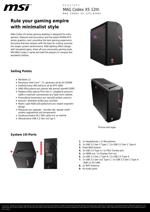
Rule your gaming empirewith minimalist styleMAG Codex X5 series gaming desktop is designed for entrygamers, features Intel processor and the latest NVIDIA RTXseries graphics card, providing the best gaming experience.Exclusive thermal solution with the best air cooling, promisethe longer system performance, RGB lighting effect designwith tempered glass, show off your personally gaming style,MSI MAG Codex 5 series will lead the players to conquer thewonderful battles.Selling PointsWindows 11Procesory Intel Core™ 12. generace až do i9-12900KGrafické karty MSI GeForce až do RTX 3090Větší šířka pásma pro přenos dat pomocí paměťí DDR5Podpora šířky pásma PCIe Gen 5, vylepšená pracovnízátěž a možnosti vykreslování pro lepší herní zážitek.Promyšlená konstrukce pro nejvyšší průtok vzduchuKovové i skleněné dvířka jsou součástíMystic Light RGB LED podsvícení pro vlastní originálnídesignPřipraven pro upgrade - navržen tak, abyste mohlisnadno upgradovat své komponentyVysokorychlostní M.2 SSD načte hru ve vteřiněOboustranný USB 3.2 Gen 2x2 typ CPicture and logosSystem I/O-Ports1.1x Headphones / 1x Microphone2.1x USB 3.2 Gen 1 Type C / 2x USB 3.2 Gen 1 Type A3.Flash BIOS button4.2x USB 2.0 Type A / 1x PS/2 Combo port1x HDMI out / 1x Display Port out5.6.2x USB 3.2 Gen 1 Type A / 2x USB 2.0 Type A7.1x USB 3.2 Gen 2x2 Type C / 1x USB 3.2 Gen 2 Type A/ RJ45 (2.5G LAN)8.2x WiFi Antenna9.6x Audio jacksSpecificationOperating Systems N/ACPU Number Intel Core i9-12900KFCPU Clock 3.2GHzCPU Cores6,16TDP125WCache30 MB Intel® Smart Cache Threads24CPU Cooler Liquid cooling 150WChipsets Z690VGA IO Port HDMIx1, Display Portx3VGA MKT Name GeForce RTX 3090 VENTUS 3X 24G GPU1 VRAM Size24GMemory Size64GB(32GB*2)Memory Type DDR5 SDRAMMemory Speed2400(4800)MHzModule Type U-DIMMMemory Slot(Total)4Memory Slot(Free)2Max Capacity Max 128GBSSD Interface PCIe GEN4x4 NVMeSSD Form Factor M.2-2280 M-KEYSSD Config2TB*1SSD Size2TBHDD1 Interface SATA GEN3HDD1 Form Factor 3.5 inchHDD1 Size2TB*1HDD1 RPM7200RPMODD(Type)N/AODD Height N/AODD Type N/AM.2 slots(Total)4M.2 slots(Free)32.5" Drive Bays(Total)22.5" Drive Bays (Free)2LAN Intel I225-VWLAN INTEL/AX211.NGWG.NVWLAN Version802.11ax 2x2+BTBT Version 5.2Audio Chipset Realtek ALC897Audio Type7.1 Channel HD Audio Thunderbolt N/AUSB 2.0 Type A NAUSB 2.0 Type C NAUSB 3.2 Gen 1 Type A2USB 3.2 Gen 1 Type C1USB 3.2 Gen 2 Type A NAUSB 3.2 Gen 2 Type C NAUSB 3.2 Gen 2x2 Type C NAUSB 3.2 Gen 2x2 Type A NAAudio Mic-in1Audio Headphone-out1Audio Headphone-out (HiFiSPDIF)NAMic-inHeadphone-out combo NAUSB 3.2 Gen 2x2 Type C (R)1USB 3.2 Gen 2x2 Type A (R)1USB 3.2 Gen 2 Type C (R)NAUSB 3.2 Gen 2 Type A (R)NAUSB 3.2 Gen 1 Type C (R)NAUSB 3.2 Gen 1 Type A (R)2USB 2.0 Type C (R)NAUSB 2.0 Type A (R)4Thunderbolt (R)NARJ451WiFi Antenna N/ACard Reader NAVGA out NAVR-Link NAHDMI out1x (v2.0)DP out1x (v1.4)mini DP in NAmini DP out NAPS21COM Port NADVI-D out NAAudio jack6SPDIF NAFlash BIOS Button1Operating, Storage Temperature0° C ~ 35° C ; -20° C ~ 60° C Operating, Storage Humidity0% ~ 85%;0% ~ 90%Regulatory Compliance FCC(Class B)CB/CEUL(CUL)BSMIVCCIRCM(C-Tick)Power850WPower Certification80plus GoldFormfactor ATXType POWER SUPPLYProduct Dimension (WxDxH) (mm)195 x 514.8 x 466Product Dimension (WxDxH) (inch)7.68 x 20.27 x 18.35Inside Carton Dimension (WxDxH) (mm)N/AInside Carton Dimension (WxDxH) (inch)N/A575(W/O KB) x 320(W/O KB) x 660(W/O KB) Outer Carton Dimension Standard (WxDxH)(mm)Outer Carton Dimension Standard (WxDxH)575(W/O KB) x 320(W/O KB) x 660(W/O KB) (inch)Weight (Net kg)TBDWeight (Gross kg)TBDLiter40VESA size NAKeyboard Interface N/AMouse Interface N/APower Cord1AC Adaptor N/AWarranty Card1Quick Guide5User Manual N/AVESA Mount kit N/AKeyboard N/AMouse N/AWarranty24monthsColor ID1/Black-Black-BlackEAN4719072886004。
TRACER 5手持XRF分析仪产品介绍说明书

TRACER 5Portable XRF Analyzer for Cutting-Edge ResearchersHighlightsRh target X-ray source with interactive control of current and voltageLatest graphene window SDD technologySelectable measurement spot sizes (3 mm and 8 mm) Patented SharpBeam TM front end geometry for improved analysis precisionHelium purge capable5 position automatic filter changerManual filter / secondary target optionInternal sample camera for accurate measurement positioningIntegrated processor and data storageWi-Fi and USB connectivity to PCBruker Instrument Tools (BIT) PC softwarepackage enables instrument control,measurements, and communicationLive spectra directly on the TRACER 5 and on PCwith BIT and ARTAXARTAX PC software for comprehensive analysisincluding multiple spectra comparisons as well asBayesian inference and deconvolution modeling Bruker’s TRACER 5 handheld XRF analyzer provides unprecedented capabilities for sophisticated users. It synchronizes advanced technology with power, function, precision, and accuracy to providedynamic, field capable elemental analysisfrom everyday point-and-shoot testingto the complexities of cutting-edgematerials research. Elements as light asfluorine and sodium can be measured. The user can control current and voltage settings as well as utilize user changeable collimators and custom filters. The TRACER 5 enables scientists to visualize, identify, and analyze the relative elemental content of almost any substance on earth and beyond.Elemental Analysis from Fluorine to UraniumThe TRACER 5 handheld XRF spectrometer is based on the principle of energy dispersive X-ray fluorescence (XRF) for non-destructive elemental analysis of materials.Design and PerformanceThe TRACER 5 utilizes a high-performance graphene window silicon drift detector (SDD). It incorporates this latest detector technology with a 50 kV (4 W) rhodium end-window tube and SharpBeam™ front-end geometry providing maximum count rate and a scatter-minimized, clean spectrum. Combined with a helium beam path, it enables detection of elements lighter than any other handheld XRF analyzer on the market.Operator FriendlinessDesigned as both a “point and shoot” and“cutting-edge research” analyzer, the TRACER 5 requires minimal setup and operator training. Equipped with both user level and supervisor-level access, a manager can choose to grant basic operator control or full functionality. This two-tier approach and intuitive interface make the TRACER 5 perfect for both beginning users, as well as power users.The user interface has been designed to provide intuitive operation, including interactive control of measurement conditions. Results can be clearly viewed as composition, pass/fail, and live spectra. Data management and transfer are exceedingly easy to use via Wi-Fi or wired USB.Advanced Handheld XRF T echnologyUltimate FlexibilityThe TRACER 5 can be configured with factory ready calibrations which incorporate preset power, filter, collimator setting, beam path atmosphere, and measurement time. It also provides user control of all those settings for a fully lab-like instrument experience. Operators can select optimum excitation voltage and current settings, filter material, collimator spot size, and beam path atmosphere of air or helium. The TRACER 5 is designed with IP54 towithstand field operation in all environments, including humid and dusty conditions. TheTRACER 5 can be operated at wide temperature range of -10 °C to 50 °C (14 °F to 122 °F).The TRACER 5 incorporates an Easy Access™ rail mount to provide easy mounting for numerous accessories including a tripod, extension pole, soil foot, smartphone, andcollapsible desktop stand kit.TRACER 5 desktop stand kit with safety shield in placeTRACER 5 interactive user interface for control and resultsComprehensive FeaturesLatest Graphene WindowThe TRACER 5 incorporates a large area graphene window silicon drift detector (SDD). The graphene window replaces the traditional 8 μm beryllium window. This groundbreaking window is one of the first commercial usesfor graphene, an advanced material composed of atomic layers of carbon atoms arranged in hexagonal lattices.While the graphene is extremely thin, its unique structure makes it extremely strong. The graphene window has higher transmission of X-rays throughout the energy transmission for light elements such as fluorine, sodium, magnesium, silicon, and aluminum. The improved light element sensitivity enables lower detection limits and faster analysis. SharpBeam TM Optimized Geometry Every TRACER is precision built with Bruker’s patented SharpBeam TM Optimized Geometry including benefits, such as:produces a sharp, defined measurementspotimproves measurement precisionreduces power requirementsreduces stray scatterincreases battery lifereduced instrument er Changeable Collimators and Custom FiltersThe TRACER 5 is designed with a portal to enable manual use of changeable collimators and filters. A TRACER 5 is supplied with two collimators, one which generates an 8 mmoval spot and one a 3 mm oval spot. Use of the 3 mm collimator provides a measurement area for the isolation of a small feature to be tested. The larger 8 mm spot size is preferable for inhomogeneous materials and bulk samples.In addition to its 5-position filter wheel with industry-standard handheld XRF filters for preset factory calibrations, the TRACER 5 also enables use of custom filters for unique sample analysis. To adapt custom filter materials, various manualfilter accessories are available.Portal for user changeable collimators (3 mm bottom leftand 8 mm bottom right) and custom filtersAir is the standard atmosphere for measuring heavy metals in multiple matrices, heavy elements (Ti to U) in multiple matrices, and light elements (Mg to Zn) in heavy metal alloy matrices.To get the best signal for light elements, air needs to be removed between the sample and detector. This can be accomplished by purging with helium through a port connection (seebelow) that significantly improves measurements for very light elements (F to P) in multiple matrices.ARTAX PC SoftwareThe ARTAX PC software provides the ability to visualize, identify, and analyze the relative elemental content of almost any substance. This easy-to-use spectral analysis software enables the determination of how elements interact within their sample set. It provides a project management data base which can contain hundreds of thousands of spectra and can be organized in a logical structure for a given ers can apply their own subject matterexpertise to guide analysis while the software applies advanced mathematics involved in Bayesian analysis of the spectra. Outputs from ARTAX software are in Excel format, so they can be imported into any of the analysis programs already in use.Integrated CameraThe TRACER 5 is equipped with an internal CMOS camera to provide sample visualization and precise alignment of the target sample area using an oval spot or a reticle projected onto the sample image. Up to five images can be stored with each spectrum for later identification of the sample area analyzed.camera features ensure accurate measurementpositioning, even for very small 3 mm spots up to five images per assay can be saved to provide visual measurement recordsimages can be easily imported into reportsSelectable Beam Path – Air or HeliumAtmosphere will impact the results obtained in an XRF measurement, especially for light elements like F, Na, Mg, Al, Si, and P. Anymaterial between the sample and detector will absorb some of the low-energy X-rays emitted by the sample before they arrive at the detectorto be counted.Integrated camera for targetting sample areasPort connection (red circle) to purge with heliumApplications and Calibrations Bruker’s TRACER 5 handheld XRF analyzerwith its advanced and unique features andsoftware enables elemental analysis of almostany substance. It can be used for in-situmeasurements and set up in a desk top stand forsmall or prepared samples. It can be configuredwith both unique and common factory pre-loadedcalibrations which provide results as identifiedmetals and alloys, elemental composition,or pass/fail. The TRACER 5 also enablescomprehensive compositional and spectralanalysis for specialized applications including:Archaeological StudiesThe TRACER 5 not only helps investigatehomogenous samples, but also complex,heterogeneous, and non-uniform samples.This is especially important for archaeologicalresearch to identify, compare, and quantifyelements of sample materials in the context oftheir environment. The TRACER 5 helps provideimmediate information for dynamic scientificinsight into found objects, artifacts, and theirsurroundings including ceramic, bone, obsidian,glass, metal, and soil.Art Conservation and AuthenticationThe Bruker TRACER 5 handheld-XRF is thebenchmark portable analytical solution forcultural heritage elemental analysis used byexperts the world over in laboratories, galleries,and on-site locations. It’s an essential tool formeeting multiple objectives in the analysis offine art, architecture, objects, adornments,sculpture, and more:Research and interpretationDetermine of original materialsAuthentication of origin or contextGuidance for conservation and restorationSemiconductor ManufacturingThe TRACER 5 enables measurements offluorine compounds which are used for a varietyof semiconductor manufacturing applicationsincluding chemical vapor deposition, plasmaetching, and cleaning.Natural Resource InvestigationsThe TRACER 5 provides comprehensive field portable solutions for natural resource research. It helps to measure and map majors, minors, and target elements of ores, cores, drill cuttings, soil, and sediment:Chemostratigraphy and quantitative characterization of geologic samplesCompositional oceanographic studies for exploration, utilization, and preservationEnvironmental assessments for heavy metals, mineral nutrients, and sodicity in soils and plantsMaterials Research and EducationThe TRACER 5 flexibility to analyze both uniform and non-uniform materials with and without standard reference samples makes it a perfect choice for both research and teaching. The TRACER 5 helps provide students experiential, value-driven science with near-instant feedback to engage them in the classroom, on field trips with real-world samples, and even in the lab.Factory User-Ready CalibrationsA wide range of unique and common factory calibration options is available for the TRACER 5. These calibrations can be customized to perfectly fit specific requirements. Customers can also create and modify their own custom empirical calibrations with Bruker’s EasyCal PC software.TRACER 5 common calibration examples are:Alloys and MetalsPrecious MetalsHeavy Metals and Nutrients in Soil; PlantsGeoExploration; LimestoneConsumer Safety Restricted Materials TRACER 5 unique calibration examples are:Ancient Copper AlloysCustomized CeramicsGlassMudrockObsidianDrill core analysisAnalysis of obsidianPC software with measurement setting control, drop down menu of preloaded calibrations, and data processing options.Technical SpecificationsBruker Nano AnalyticsHeadquarters Berlin · Germany Phone +49 (30) 670990-0 Fax +49 (30) 670990-30 *******************/tracerA l l c o n f i g u r a t i o n s a n d s p e c i f i c a t i o n s a r e s u b j e c t t o c h a n g e w i t h o u t n o t i c e .© 2022 B r u k e r N a n o G m b H , A m S t u d i o 2D , 12489 B e r l i n , G e r m a n y . O r d e r N o .D O C -B 83-E X S 003.。
altanium matrix5 用户指南说明书
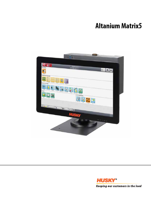
Altanium Matrix5用户指南原始说明发行:v 1.0 — 2020 年 2 月本产品手册的目的是提供有关安全操作和/或维护的信息。
Husky 保留对产品进行更改的权利,以便不断改进产品功能和/或性能。
这些更改可能导致不同和/或额外的安全措施,在进行更改时,将通过公告向客户传达这些措施。
本文包含的信息是 Husky Injection Molding Systems Limited 的专有财产。
除合同明确授予的任何权利外,未经 Husky Injection Molding Systems Limited 事先书面许可,不得对本文全部或部分内容进行进一步发布或商业使用。
尽管有上述规定,但 Husky Injection Molding Systems Limited 仍允许其客户仅出于有限内部使用的目的而复制本文。
这些资料中引用的 Husky® 产品或服务名称或徽标是 Husky Injection Molding SystemsLimited 的商标,其某些附属公司可在许可下使用它们。
所有第三方商标均为各自第三方的财产,可能受适用版权、商标或其他知识产权法和条约的保护。
每个此类第三方均明确保留对此类知识产权的所有权利。
© 2019 Husky Injection Molding Systems。
保留所有权利。
iiiii一般信息电话支持号码有关现场服务,请联系最近的 Husky 地区服务和销售办事处。
有关非紧急问题,请向 Husky 发送电子邮件,电子邮件地址为 ********************。
Husky 地区服务和销售办事处有关最近位置,请访问 www.husky.co 。
产品升级可获得升级,升级可改善输出,缩短周期时间,以及为 Husky 设备增加功能。
要查看可获得哪些升级,请访问 www.husky.co ,或者致电最近的 Husky 地区服务和销售办事处。
罗克韦尔自动化发布Studio 5000新版软件
netRAPID模 块 不 仅 支 持 实 时 工 业 以 太 网 通 讯 ,软 件 协 议栈 还 集成 了W ebserver功 能 和 一个 透 明 的 以太 网 通道 ,通过 TCP Socket模 式 或 者RAW Ethernet模 式 ,HOST主 机应 用 程 序可 以很 便 捷地 与 软件 协议栈 进行 数据 交互 。在RAW Ethernet模式 下 ,通过 独立 的 MAC地 址建 立 连接 通讯 ,其 应 用也 就 相 当于网 络中 的一 个独立 设备 。
为 了推 动 用 户 的开 发 进 程 ,罗克 韦尔 自动 化还 在 Studio 5000 Application Code Manager中添 加 了一 个M achine Builder库和 过 程 对 象 库 。这 两 个 库 均 可 从 产 品 兼 容 性 下 载 中 心 (PCDC)免 费 下 载 。除 了改 进的用 户界 面 之用 程 序 现在 还提 供 一个 更 新 的接 口,用 于连接 Cape Software VP Link和M YNAH Mimic 等操作 员培 训系 统 。
MAG Trident S 5M 桌面电脑说明书
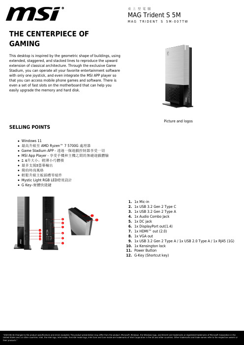
THE CENTERPIECE OFGAMINGThis desktop is inspired by the geometric shape of buildings, usingextended, staggered, and stacked lines to reproduce the upwardextension of classical architecture. Through the exclusive GameStadium, you can operate all your favorite entertainment softwarewith only one joystick, and even integrate the MSI APP player sothat you can access mobile phone games and software. There iseven a set of fast slots on the motherboard that can help youeasily upgrade the memory and hard disk.Picture and logosSELLING POINTSWindows 11最高升級至 AMD Ryzen™ 7 5700G 處理器Game Stadium APP - 透過一個遊戲控制器享受一切MSI App Player - 享受手機和主機之間的無縫遊戲體驗2.6升大小,輕薄小巧體積最多支援3螢幕輸出簡約時尚風格輕鬆升級主板插槽零組件Mystic Light RGB LED燈效設計G Key–實體快捷鍵1.1x Mic-in2.1x USB 3.2 Gen 2 Type C3.1x USB 3.2 Gen 2 Type A1x Audio Combo Jack4.5.1x DC jack6.1x DisplayPort out(1.4)7.1x HDMI™ out (2.0)8.1x VGA out9.1x USB 3.2 Gen 2 Type A / 1x USB 2.0 Type A / 1x RJ45 (1G)10.1x Kensington lock11.Power Button12.G-Key (Shortcut key)SPECIFICATIONOperating Systems Operating Systems Windows 11 Home Barcode Info EAN4719072920890Model Part No9S6-B93611-007MKT Name MAG Trident S 5MMKT Spec MAG Trident S 5M-007TW Color ID1/Black-Black-BlackProcessor CPU Number AMD Ryzen 5 5600G CPU Clock 3.9GHzCPU Cores6TDP65WCache3MBThreads12CPU Cooler Air cooling 3HPChipset Chipsets N/AGraphics VGA I/O Port N/A VGA MKT Name N/AMemory Memory Size16GB(8GB*2) Memory Type DDR4 SDRAM Memory Speed1600(3200)MHz Module Type SO-DIMM Memory Slot (Total/Free)2/0Max Capacity Max 64GBStorage SSD Size512GBHDD1 Size N/ASSD Config512GB*1SSD Interface PCIe GEN3x4 w/o DRAM NVMe SSD Form Factor M.2-2280 M-KEYM.2 slots (Total/Free)2/1HDD1 RPM N/AHDD1 Form Factor N/AHDD1 Interface N/A3.5" Drive Bays (Total/Free)0/2.5" Drive Bays (Total/Free)1/1ODD(Type)N/AODD Height N/AODD Type N/ACommunications LAN Realtek RTL8111HWLAN INTEL/AX210.NGWG.NV WLAN Version802.11a/b/g/n/ac/ax 2x2+BT BT Version 5.2Audio Audio Chipset Realtek ALC233 Audio Type 2.1 Channel HD AudioI/O Ports (Front)USB 3.2 Gen 1 Type A1 USB 3.2 Gen 2 Type A1 USB 3.2 Gen 2 Type C1 Audio Mic-in1 Mic-in/Headphone-out combo1I/O Ports (Rear)USB 3.2 Gen 2 Type A (R)1USB 2.0 Type A (R)1RJ451WiFi Antenna1VGA out1HDMI™ out1x (v2.0) DP out1x (v1.4)Power Power120W Power Certification N/A Formfactor N/A Type ADAPTORAccessories Keyboard Interface N/A Mouse Interface N/A Power Cord1 AC Adaptor1 Warranty Card N/A Quick Guide2 User Manual N/A VESA Mount kit N/A Keyboard N/A Mouse N/AMechanical and Environmental Operating, Storage Temperature0° C ~ 35° C ; -20° C ~ 60° C Operating, Storage Humidity N/ARegulatory ComplianceFCC(Class B)CB/CEUL(CUL)BSMIVCCIRCM(C-Tick)Dimension&Weight Product Dimension (WxDxH) (mm)185.4 x 93 x 334.7 Product Dimension (WxDxH) (inch)7.3 x 3.66 x 13.18 Inside Carton Dimension (WxDxH) (mm)N/AInside Carton Dimension (WxDxH) (inch)N/AOuter Carton Dimension Standard (WxDxH) (mm)482 x 144 x 325 Outer Carton Dimension Standard (WxDxH) (inch)18.98 x 5.67 x 12.8 Weight (Net kg)N/AWeight (Gross kg)N/ALiter2LWarranty Warranty36months。
Ashly neWR-5 远程控制说明书
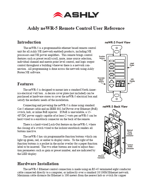
Ashly neWR-5 Remote Control User Reference Introduction The neWR-5 is a programmable ethernet based remote control unit for all Ashly NE (network enabled) products, including NE processors and NE power amplifiers. This remote brings control features such as preset recall/scroll, mute, zone source selection, individual channel and matrix point level control, and logic output control throughout a building wherever there is a network con-nection. All programming is done across the network using Ashly Protea NE software. FeaturesThe neWR-5 is designed to mount into a standard North Amer-ica electrical wall box. A decora cover plate (not included) can be satisfy the aesthetic needs of the installation.Connecting and powering the neWR-5 is done using standard switch, hub, or inline PoE injector. If PoE is unavailable, a 15-hard wired to a euroblock connector on the back of the remote.There is a hard-wired Lock-Out feature on the neWR-5, where the closing of a switch wired to the lockout euroblock renders all buttons inactive. light up green, red, or amber to display status. To the right of the label to be inserted. The two other buttons are used to adjust func-tion parameters such as gain or preset number, and are indicated by the LED display.Hardware InstallationThe neWR-5 Ethernet control connection is made using an RJ-45 terminated eight conductor cable connected directly to a computer, or indirectly over a standard 10/100M Ethernet network. Maximum cable distance for Ethernet is 100 meters from the nearest hub or switch for copper Operating Manual - neWR-5 Remote Control for NE Products2twisted pair CAT5 cable. If using PoE, no further power supply is required, otherwise connect a 15-48VDC power supply to the neWR-5 via the labelled is 38mA @48VDC.If desired, wire the Lock Out con-nector to an external remote or keyed switch.Upon connecting and powering up the system, the WR-5 will have a “heartbeat”, meaning an internal small green LED on the PCB (behind the display bezel) will be flashing. After power up, the LED displays “- -”. If there is a two-digit number showing in the display, that means the WR-5 has for that zone.Mount the neWR-5 to a wall box as shown (decora plate and wall box not included). Note: Avoid static shock disruptions to this or other connected devices by mounting the neWR-5 to an earth-grounded metal wall box, or by earth-grounding a metal decora plate. This prevents static discharge from flowing through the data lines.Protea NE SoftwareAshly NE products installed on the network will be automatically detected and displayed in the active device menu tree on the left side of the Protea NE software startup screen. The software scans for active NE devices every time it loads, but the user can manually scan at any time as well with <Scan For Devices> at the bottom of the network NE device listing. All NE devices continu-ously broadcast their availability to the software. All currently connected and active NE products are highlighted in green, while NE products which have been formerly installed but are currently off-line or unavailable show up in red. Individual NE products can be dragged onto the project canvas to simulate physical installation groups, but editing each product can be done from either the menu tree or the project canvas. Lines, rectangles, text, and image files can be added to create a custom virtual control screen along with NE products and individual control objects. To see all available canvas tools, right click anywhere over open canvas. Projects, including all device settings and canvas drawings, can be saved as a file. Checking <Design Mode> (right-click on canvas) allows placed objects to be moved around, while unchecking <Design Mode> locks objects in place. Once an image has been placed on the canvas, it must be deleted by hand if that device is no longer available to the software. Scanning for devices does not automatically remove images which may have been installed at one time but are now off line. To clear the canvas of all devices and drawn elements click <File - New>. Further neWR-5 help is available in Protea NE software by navigating through the online help menu.Operating Manual - neWR-5 Remote Control for NE ProductsMain Control SurfaceThe main control surface is where the neWR-5 is named, its target NE device gets selected, any zone definition occurs, and where the function buttons are programmed, The neWR-5 comes with all function buttons set to “Off”. Unlike the WR-5, changes must be saved to the neWR-5 before becoming effective. Not all of the button functions listed below are available on all NE products, for instance an amplifier will not have “matrix mixer” capability unless it has DSP installed, and some products do not have logic outputs. Protea NE software is able to determine which functions are available for neWR-5 control.1) Off - No function assigned and the button’s LED remains unlit2) Preset Recall - A single preset number is assigned to a button. When the button is pressed, the recalled preset number and the letters “PC” (Preset Change) are alternately flashed on the WR-5 for five seconds, also locking out any other WR-5 action for that time.3) Preset Scroll Mode - A range of presets can be assigned to a function button which when selected, enables the up/down buttons to scroll through the available presets. Upon release of the up/ down button, the currently displayed preset will load. The function button will glow amber for the duration of the preset scroll operation.4) Gain Control - Since there are many possible gain adjustment points within a given NE au-dio processing device, the neWR-5 displayed gain level is only a relative value. In other words, gain could be changed elsewhere in the target unit, independent from neWR-5 control. The neWR-5 can adjust gain from 0 to 99, and an upper and lower number limit can be set in the function range sec-tion to limit the maximum and minimum reach of that control. To control the gain within the target device’s input or output signal path, the neWR-5 remote gain function must first be inserted into a block in the unit’s DSP controls window.Gain Control over individual channel(s) - When a gain control button is assigned to control one or more individual channels, pressing that button will cause it to light amber, during which time the up/down buttons determine gain for the selected channels. If the up/down buttons remain idle for five seconds, the gain button becomes inactive until being pressed again. Gain Control over zone - If a zone output is active for that neWR-5, meaning one or more output checkboxes are selected within the neWR-5 Zone Setup mode, the output gain for that zone will be shown as the default numerical display, during which time the up/down buttons stay ac-tive for that zone’s overall gain control. If a button is assigned for individual input channel(s) gain control in addition to the neWR-5 being defined for output zone control, that button will turn amber when pressed, and both the neWR-5 up/down buttons and display will reflect the input channel(s) gain, reverting back to output zone gain after five seconds of inactivity. If there is no zone output assigned for the neWR-5, the display shows “--” as the default.5) Channel Engage/Mute - A button can be configured to mute one or more inputs or outputs, or any combination of the two. The button is green when engaged and red when the selected chan-nels are muted.3Operating Manual - neWR-5 Remote Control for NE Products6) Zone Source Selection - This function is used to assign a button to select one or more inputs for the defined zone (Select Zone Outputs) under neWR-5 control. Any function button can have any combination of inputs as sources. A zone source selection button is green when selected, and red when unselected. When multiple zone source select buttons are assigned different or over-lapping inputs, each button will simply add to or subtract from the other’s input selections. How-ever, if the Exclusive Source Selection box is checked in the zone setup, only the currently selected button’s inputs will be used for that zone.The <Disable Zone Level Control> checkbox allows input source selections to be changed from the neWR-5, but not the overall output gain for that zone. The output gain can still be adjusted from the target device software, but the neWR-5 user is locked out from making output zone gain changes.7) Logic Output Active High - This allows the user to toggle the Logic Output assigned pin to the button. The switch turns green when the output is high.8) Logic Output Active Low - The switch turns green when the output is Low.9) Matrix Mixer - This is used to select one or more inputs for the zone under neWR-5 con-trol, but allows level control of that group at the dsp matrix mixer point instead of the output. Select one or more Zone Output(s) in the Zone Setup to use the Matrix Mixer functionSecurityIn addition to the hardware lockout available on the neWR-5, there are multiple user/multiple levels of software protection assignable to the neWR-5 within the Security tab, from full access to view only. The security data is stored within the neWR-5 itself, not Protea NE Software. Passwords are case sensitive . Be sure to write down the password and store in a convenient place for future reference. Network PropertiesHardware, device, and device network configuration details are displayed in the network prop-erties tab. This includes the current neWR-5 firmware revision.Flash ReprogramThe firmware, meaning the internal program which runs on the neWR-5, can be updated easily over the network. Look in network properties for the current firmware revision. To obtain the latest firmware, visit the Ashly Web site, locate and save it to the computer, then run <Flash Reprogram> under the Device Options menu. The LED displays “Pr” during the reprogramming process.Factory ResetTo restore factory default settings, a factory reset can be performed by connecting power to the unit while holding the top function button down for 10 seconds, during which time a countdown will occur on the LED display. Releasing the button at any time prior to completion of the countdown stops the process. Upon completion of the countdown, the LED displays “Fr” until the neWR-5 is reset.2011 by Ashly Audio Corporation. All rights reserved worldwide.Printed in USA 0111 R1Ashly Audio Inc 847 Holt Rd Webster NY 14580585-872-0010 toll free 800-828-6308 fax 585-872-0739 。
expert advisor programming for metatrader 5 译本

expert advisor programming for metatrader 5 译本Expert Advisor programming for MetaTrader 5 is a sophisticated tool that allows traders to automate their trading strategies.By creating an Expert Advisor, traders can implement their trading algorithms and execute trades automatically without manual intervention.This can be particularly useful for those who want to free up their time and focus on other aspects of their trading business.MetaTrader 5平台上的专家顾问(Expert Advisor)编程是一种复杂的工具,它允许交易者自动化他们的交易策略。
通过创建一个专家顾问,交易者可以实施他们的交易算法并自动执行交易,而无需人工干预。
这对于那些希望节省时间并专注于交易业务其他方面的人来说特别有用。
The Expert Advisor programming language is based on MQL5, which is a scripting language specifically designed for MetaTrader 5.It is a powerful language that allows traders to create complex algorithms and strategies.With MQL5, traders can access a wide range of functionalities, such as historical data analysis, real-time market monitoring, and automated trading execution.专家顾问编程语言基于MQL5,这是一种专门为MetaTrader 5设计的脚本语言。
Transcend StoreJet 2.5 用户手册说明书
StoreJet™ 2.5 User’s Manual(Version 1.2)Table of ContentsIntroduction (1)Package Contents (1)Features (2)System Requirements (2)Safety Precautions (3)General Use (3)Backing Up Data (3)Transporting (3)Power (3)Reminders (4)Product Overview (5)Installing a Hard Drive (6)Driver Installation (9)Driver Installation for Windows® 2000, XP and Vista (9)Driver Installation for Mac™ OS 9.0, or Later (9)Driver Installation for Linux™ Kernel 2.4, or Later (9)Connecting to a Computer (10)Disconnecting from a Computer (12)Removing the StoreJet™ 2.5 in Windows® 2000, XP and Vista (12)Removing the StoreJet™ 2.5 in Mac™ OS 9.0, or Later (12)Remove the StoreJet™ 2.5 in Linux™ Kernel 2.4, or Later (12)Formatting the Hard Drive (13)Windows® 2000/XP (13)Windows Vista™ (14)Troubleshooting (18)StoreJet™ 2.5 IDE series (20)StoreJet™ 2.5 SATA series (22)Transcend Limited Warranty (23)IntroductionCongratulations on purchasing Transcend’s StoreJet™ 2.5.This tiny, Ultra-portable, Hi-Speed USB storage device is the perfect data management system for uploading, downloading, storing and transferring your vital data and information. With a huge storage capacity and Hi-Speed USB 2.0 data transfer rates, the compact StoreJet™ 2.5 is ideal for storing and transferring your files, folders, documents, photos, music and e-work between it and any desktop, or notebook computer. In addition, the StoreJet™ 2.5 comes with a very useful software (please see the Software User’s Manual for detailed instructions) pack that can (used in Windows®) increase your productivity. The User’s Manual and accompanying Software User’s Guide are written to help you get the most from your new device, please read both in detail before using the StoreJet™ 2.5.Package ContentsThe StoreJet™ 2.5 package includes the following items:•StoreJet™ 2.5•Mini USB to USB A-Type cable (USB Y cable)•Quick Instruction GuideFeatures•Hi-Speed USB 2.0 compliant and USB 1.1 backwards compatible•Easy Plug and Play installation•Optional 2.5” Hard Disk Drive•Ultra-Portability•OneTouch Auto-Backup function•Powered via the USB port. No external power or battery needed•Hi-Speed data transfer rates up to 480Mbits per second•Additional StoreJet Software pack: Transcend Elite (helps you manage your data) •LED indicates the status of power on, data transfer activitySystem RequirementsDesktop or notebook computer with a working USB port.One of following Operating Systems (OS):•Windows®2000•Windows®XP•Windows®Vista•Mac™ OS 9.0, or later•Linux™ Kernel 2.4, or laterSafety PrecautionsThese usage and safety guidelines are IMPORTANT!Please follow them carefully.Your StoreJet ™ 2.5 is connected to a computer using a Mini USB (on the StoreJet ™) to USB A-Type (on a Desktop, Notebook) cable. Please ensure that you connect the cable ends to the ports correctly.General Use• Carefully unpack the contents of the StoreJet ™ 2.5 package.• During operation, avoid exposing your StoreJet ™ 2.5 to extreme temperatures above 55℃, orbelow 5℃.• Do not drop your StoreJet ™ 2.5.• Do not allow your StoreJet ™ 2.5 to become damp or wet from water or any other liquids. • Do not use a damp/wet cloth to wipe or clean the exterior case.• Do not use or store your StoreJet ™ 2.5 in any of the listed environments:o Direct sunlighto Next to an air conditioner, electric heater or other heat sources o In a closed car that is in direct sunlightBacking Up Data• Transcend does NOT take any responsibility for data loss, or damage during operation .If you decide to store data on your StoreJet ™ 2.5 we strongly advise that you regularly backup the data to a computer, or other storage medium.• To ensure High-Speed USB 2.0 data transfer rates when using your StoreJet ™ 2.5 with acomputer, please check that the computer has the relevant USB drivers. If you are unsure about how to check this, please consult the computer or motherboard User’s Manual for USB driver information.Transporting• Do not pack your StoreJet ™ 2.5 into luggage without the proper padded support. Other itemsin the luggage may damage your StoreJet ™ 2.5 if it does not have the proper protection.• Avoid squeezing your StoreJet ™ 2.5 to prevent damage to the internal HDD. • Avoid placing objects onto your StoreJet ™ 2.5 to prevent damaging it.Power• The StoreJet ™ 2.5 is powered directly via a computer USB port; however, the power suppliedby the USB port on some older computers is below the required 5V DC power. In this instance, please connect the other USB A-Type connector from the provided USB Y cable to a USB port on the computer, this will provide the additional power necessary to run the drive.The other USB A-Type connector is used to provide additional power.•Please use the Mini USB to USB A-Type cable that came with the StoreJet™ 2.5 to connect it to a computer, and always ensure that the cable you are using is in good condition. NEVERuse a cable that is frayed or damaged.•Ensure nothing is resting on the USB cable and that the cable is not located where it can be tripped over or stepped on.RemindersAlways follow the procedures in the “Disconnecting from a Computer” section to remove your from a computer.StoreJet™Product OverviewFigure 1. StoreJet 2.5Screws x 2 Mini USB PortOneTouch Auto-Backup ButtonP r o d u c t O v e r v i e wInstalling a Hard DriveInstalling a Hard DriveIf you purchased a StoreJet ™ 2.5 that does not have a Hard Disk Drive already installed, please read this section, otherwise you can skip to the “Driver Installation ” section.1. Open the StoreJet ™2.5 by removing the two screws from either side of the top cover, as indicated inthe diagram.Figure 2. Remove the screws from the top cover2. Remove the cover revealing a control board adapter; this converts the IDE/SATA interface connectorof the hard drive to a Mini USB 2.0 interface. Slide out the control board.Figure 3. Remove the top cover revealing the IDE/SATA adapter3. Carefully line up and plug in the IDE/SATA connector on the control board to the hard drive. Do NOTforce the IDE/SATA connector into the hard drive and do NOT insert the connector at an angle, otherwise you may damage it.I n s t a l l i n g a H a r d D r i v eFigure 4. Connect the hard drive to the IDE/SATA adapter4. Carefully reinsert the IDE/SATA adapter and its connected 2.5” hard drive into the StoreJet ™ 2.5 andreattach the screws to the top cover.Figure 5. Reinsert the adapter plus drive and reattach the screwsI n s t a l l i n g a H a r d D r i v eDriver InstallationDriver Installation for Windows ® 2000, XP and VistaNo drivers are required. These Windows ® Operating Systems have built-in drivers to support the StoreJet ™ 2.5. Plug your StoreJet ™ into an available USB port and Windows will install the necessary files. A new Local Disk drive with a newly assigned drive letter representing the StoreJet ™ 2.5 will appear in the My Computer window.Driver Installation for Mac ™ OS 9.0, or LaterNo drivers are required. Plug your StoreJet ™ 2.5 into an available USB port and your computer willautomatically detect it.Figure 6. Mac Driver InstallationDriver Installation for Linux ™ Kernel 2.4, or LaterNo drivers are required. Plug your StoreJet ™ 2.5 into a USB port and mount it.1. First create a directory for the StoreJet ™2.5.Example: mkdir /mnt/Storejet2. Then, mount the StoreJet ™ 2.5.Example:mount –a –t msdos /dev/sda1 /mnt/StorejetD r i v e r I n s t a l l a t i o nConnecting to a ComputerIf you want to use the StoreJet ™ 2.5 as an External Hard Disk Drive to upload/download data to, or from your computer you will need to connect it to a USB port on the computer using the provided .Figure 7. Mini USB to USB A-Type Cable (USB Y cable)1. Plug the small end of the USB Y cable into the Mini USB port on the StoreJet ™2.5.2. Plug the large end of the cable into an available USB port on your desktop, or notebook computer.* On some older computers, the power supplied by the USB port is below the required 5V DC power. Inthis instance, please connect the other USB A-Type connector from the provided USB Y cable to another USB port on the computer. This will provide the additional power necessary to run the drive.Figure 8. Connecting to a ComputerU s e w i t h a C o m p u t e r Small EndLarge EndExtra USB connector used to provide additional power3. When the StoreJet ™ 2.5 is successfully connected to a computer the StoreJet ™’s Power LED will lightup, a newLocal Disk drive with a newly assigned drive letter will appear in the My Computer windowand a Hardwareicon will appear on the Windows System Tray. The StoreJet ™ 2.5’s internal harddrive comes formatted for FAT32.Figure 9. *F: is an example drive letter, the letter in your "My Computer" window may differ4. At this stage the StoreJet ™ 2.5 is a Peripheral device and is powered by the computer’s USB port.You can use the StoreJet ™ 2.5 as an external hard drive in conjunction with your computer to upload/download data. You can download data to the StoreJet ™ 2.5 simply by dragging and dropping files, or folders onto the Local Disk drive letter that represents theStoreJet ™ 2.5.5. If you have setup the bundled Transcend Elite you can press the StoreJet ™ 2.5’s OneTouch“Backup Button” once to Backup your data.Figure 10. OneTouch Auto-Backup Button6. Please be advised, if you are using the StoreJet ™ 2.5 with a notebook computer, it is better to run thenotebook using AC power. The reason for this is that the notebook’s battery will run out of power more quickly because the StoreJet ™ 2.5 needs to draw power from the USB port.U s e w i t h a C o m p u t e rDisconnecting from a ComputerNEVER disconnect the StoreJet™from a Computer when its LED is flashing.Removing the StoreJet™ 2.5 in Windows® 2000, XP and Vista1. Select the Hardware icon on the system tray.2. The Safely Remove Hardwarepop-up window will appear. Select it to continue.Figure 11. Safely Remove Hardware3. A window will appear stating, “The ‘USB Mass Storage Device’ device can now be safelyremoved from the system.”Figure 12. Safe to Remove HardwareWARNING! To prevent data loss, always use this procedure to remove the StoreJet™ fromWindows® 2000, XP and Vista.Removing the StoreJet™ 2.5 in Mac™ OS 9.0, or LaterDrag and drop the Disk icon that represents your StoreJet™ 2.5 into the trashcan. Then unplug your StoreJet™ 2.5 from the USB port.Removing the StoreJet™ 2.5 in Linux™ Kernel 2.4, or LaterExecute umount /mnt/Storejet to un-mount the device. Then unplug your StoreJet™ 2.5 from the USB port.UsewithaComputerFormatting the Hard DriveWARNING! Formatting the disk will erase all of the data on your StoreJet 25. You must have Administrator Rights to format in Windows 2000, XP , or Vista.Windows ® 2000/XP1.Download the StoreJet Format Utility from Transcend’s online Download Center at/Support/DLCenter/index.asp (the software can be located by selecting “Storage Devices -> StoreJet Drives -> any StoreJet product -> any StoreJet model) 2. When the download is complete, extract the downloaded ZIP file to your computer’s hard drive(not the StoreJet 25) and run the StoreJetFormatter.exe application. 3. Plug the StoreJet 25 into an available USB port on a Windows ® 2000/XP computer.4. Unplug all other USB storage devices from your computer . This is to prevent accidental formatof a different USB drive. 5. In the StoreJet Format Utility window, click the “Refresh” button. 6. The program will automatically detect the StoreJet 25 drive.7. Press “Start”.U s e w i t h a C o m p u t e r8. A confirmation window will appear. Press OK to begin formatting the drive.9. The format process may take a few minutes. When complete, an “O.K.” message will appear in thebottom right hand corner of the window.10. Click the “Close” button to finish and exit.Windows Vista™1. Download the StoreJet Format Utility from Transcend’s online Download Center at/Support/DLCenter/index.asp (the software can be located by selecting “Storage Devices -> StoreJet Drives -> any StoreJet product -> any StoreJet model)2. When the download is complete, extract the downloaded ZIP file to your computer’s hard drive (not theStoreJet 25).3. Plug the StoreJet 25 into an available USB port on your Windows Vista™ computer.4. Unplug all other USB storage devices from your computer. This is to prevent accidental format of adifferent USB drive.5. Right-click “StoreJetFormatter.exe ”and select “Run as Administrator.”6. The User Account Control window will appear. Select “Allow” to continue.7. In the StoreJet Format Utility window, click the “Refresh” button. 8. The program will automatically detect the StoreJet 25 drive.U s e w i t h a C o m p u t e r9. Press “Start”.10.A confirmation window will appear. Press OK to begin formatting the drive.U s e w i t h a C o m p u t e r11. The format process may take a few minutes. When complete, an “O.K.” message will appear inthe bottom right-hand corner of the window.Figure 15: Format Complete12. Click the “Close ” button to finish and exit.U s e w i t h a C o m p u t e rTroubleshootingIf a problem occurs with your StoreJet™ 2.5,please first check the information listed below before taking your StoreJet™ 2.5 for repair. If you are unable to solve a problem from the following hints, please consult your dealer, service center, or local Transcend branch office. We also have FAQ and Support services on our websites.Operating system cannot detect the StoreJet™ 2.5Check the following:1. Is your StoreJet™2.5 properly connected to the USB port? If not, unplug it and plug it in again. If it isproperly connected, try using another available USB port.2. Are you using the USB cable that came in the StoreJet™ 2.5 pack? If not, try using the TranscendUSB cable to connect the StoreJet™to the computer.3. The StoreJet™ 2.5 is powered directly via a computer USB port; however, the power supplied by theUSB port on some older computers is below the required 5V DC power. In this instance, please connect the other USB A-Type connector from the USB Y cable to a USB port on the computer. This will provide the additional power necessary to run the drive.4. Is your StoreJet™ 2.5 connected to the Mac™ keyboard? If yes, unplug it and plug it into an availableUSB port on your Mac™ Desktop.5. Is the USB port enabled? If not, refer to the user’s manual of your computer (or motherboard) toenable it.My computer does not recognize the StoreJet™ 2.51. A single USB port may not provide enough power for the StoreJet™2.5 to function. Make sure youplug both large ends of the USB cable directly into your computer’s USB ports.2. Avoid using a USB HUB to connect the StoreJet™ 2.5.Cannot Power ONCheck the following:1. Check that your StoreJet™2.5 is properly connected to the USB port on the computer.2. Check that the USB port is working properly. If not, try using an alternative USB port. Cannot back up my Mac™T r o u b l e s h o o t i n gThe StoreJet™ 2.5’s internal hard drive comes formatted for FAT32. If you want to backup a Mac computer you will need to format the drive for HFS+ using the Mac Disk Utility.Cannot detect the StoreJet™ 2.5 in LinuxThe StoreJet™ 2.5’s internal hard drive comes formatted for FAT32. Linux CANNOT support the NTFS file system, please reformat the hard drive to the FAT32 file system.itlrStoreJet™ 2.5 IDE seriesSpecifications•Size (L x W x H): 129 mm × 79.9 mm × 13 mm•Weight: 88g (without hard drive)•Storage Media: 2.5-inch IDE Hard Disk Drive•Power Supply: 5V DC supplied from the USB port(s)•Max. Transfer Speeds: 480Mbits per second•Operating Temperature:5℃ (41℉) to 55℃ (131℉)•Certificates: CE, FCC, BSMI•Warranty: 2-yearsOrdering InformationDevice Description Memory Size Transcend P/NStoreJet™ 2.5 Silver 0GB TS0GSJ25SStoreJet™ 2.5 Red 0GB TS0GSJ25RitifiStoreJet ™ 2.5 SATA seriesSpecificationsz Size (L x W x H): 129 mm × 79.9 mm × 13 mmz Weight: 186g (with hard drive)z Storage Media: 2.5-inch SATA Hard Disk Drivez Power Supply: 5V DC supplied from the USB port(s)z Max. Transfer Speeds: 480Mbits per secondz OperatingTemperature: 5℃ (41℉) to 55℃ (131℉)z Certificates: CE, FCC, BSMIz Warranty: 2-yearsOrdering InformationDevice Description Memory Size Transcend P/NStoreJet ™ 2.5 SATA Silver 0GB TS0GSJ25S-SStoreJet ™ 2.5 SATA Blue 0GB TS0GSJ25B-SStoreJet ™ 2.5 SATA Red 0GB TS0GSJ25R-S StoreJet ™ 2.5 SATA 160GB Blue 160GB TS160GSJ25B-SStoreJet ™ 2.5 SATA 250GB Silver 250GBTS250GSJ25S-Sif i t iTranscend Limited Warranty“Above and Beyond” is the standard we set ourselves for customer service at Transcend. We consistently position ourselves to be significantly above the industry norm, which is all part of our commitment to Customer Satisfaction.Please do not break or remove the warranty sticker on your Transcend products, as this will void your product warranty.All Transcend information, Inc. (Transcend) products are warranted and tested to be free from defects in material and workmanship and to conform to the published specifications. During the warranty period should your Transcend StoreJet ™ 2.5 fail under normal use in the recommended environment due to improper workmanship or materials, Transcend will repair the product or replace it with a comparable one. This warranty is subject to the conditions and limitations set forth herein.Duration of Warranty: The Transcend StoreJet ™ 2.5 is covered by this warranty for a period of two (2) years from the date of purchase. Proof of purchase including the date of purchase is required to collect on the warranty. Transcend will inspect the product and decide whether to repair or replace it. Transcend reserves the right to provide a functional equivalent product, or a refurbished replacement product.Limitations: This warranty does not apply to product failure caused by accidents, abuse, mishandling, improper installation, alteration, acts of nature, improper usage, or problems with electrical power. In addition, opening or tampering with the product casing, or any physical damage, abuse or alteration to the product’s surface, including all warranty or quality stickers, product serial or electronic numbers will also void the product warranty. Transcend is not responsible for recovering any data lost due to the failure of a hard drive device. Transcend’s StoreJet ™ 2.5must be used with devices that conform to the recommended industry standards. Transcend will not be liable for damages resulting from a third party device that causes the Transcend StoreJet ™ 2.5 to fail. Transcend shall in no event be liable for any consequential, indirect, or incidental damages, lost profits, lost business investments, lost goodwill, or interference with business relationships as a result of lost data. Transcend is also not responsible for damage or failure of any third party equipment, even if Transcend has been advised of the possibility. This limitation does not apply to the extent that it is illegal or unenforceable under applicable law.Disclaimer: The foregoing limited warranty is exclusive. There are no other warranties, including any implied warranty of merchantability or fitness for a particular purpose. This warranty is not affected in any part by Transcend providing technical support or advice.Online Registration: To expedite the warranty service, please register your Transcend Product within 30 days of purchase.Register online at /registration* The specifications mentioned above are subject to change without notice.Transcend Information, Inc.*The Transcend logo is a registered trademark of Transcend Information, Inc.*All logos and marks are trademarks of their respective companies.W。
- 1、下载文档前请自行甄别文档内容的完整性,平台不提供额外的编辑、内容补充、找答案等附加服务。
- 2、"仅部分预览"的文档,不可在线预览部分如存在完整性等问题,可反馈申请退款(可完整预览的文档不适用该条件!)。
- 3、如文档侵犯您的权益,请联系客服反馈,我们会尽快为您处理(人工客服工作时间:9:00-18:30)。
TracTrix™ 5 Software ManualTrix Systems ABSodra Gubberogatan 8, 416-63 Gothenburg, SWEDEN Phone: +46-31 337 90 90Fax: +46-31 337 90 99 Email: support@trixsystems.seTrix Systems, Inc.68 Smith Street, Chelmsford, MA 01824-1711, USA Phone: +1-978-256-4445Fax: +1-978-256-9593 Email: support@Copyright Trix Systems Inc. and Trix Systems AB, 2005. All rights reserved. Manual Rev 5.3Legal Notice and DisclaimerNothing from this manual may be reproduced, transferred, copied or translated to any language, in any form or by any means for any purpose. Trix Systems does not make any guarantees, neither expressed nor suggested which includes all implied guarantees, that the program will work properly when operated in a careless way or if the system does not meet the system demands. Trix Systems disclaims any responsibility of direct or indirect damage that may be caused by loss of information, computer standstill or any other loss of data or any damage that may be caused by the program.Licenses and TrademarksTrix Systems, Trix RasterServer, Trix ImageMaker, Trix Organizer, Trix TracTrix and TracTrix are trade marks of Trix Systems AB and Trix Systems, Inc. AutoCAD is a registered trademark of Autodesk, Inc. Microsoft and Windows are registered trademarks of Microsoft Corporation. All other trade names referenced herein are either trademarks or registered trademarks of their respective holders.Trix Systems reserves the right to change and improve the product. All examples and symbols used in the manual are made up and Trix Systems disclaims all responsibility for any resemblance.CAUTIONSFile formats are not standards. Variations of individual file formats exist and formats continuously evolve. Any two files sharing a common file suffix or format may not contain identically structured data. Where the software described in this manual is used to open, display, print, create or otherwise manipulate or transfer files it is the user's sole responsibility to inspect the results in order to assure accuracy and fitness for purpose. Trix Systems cannot be held liable for any omissions, additions or changes in content. The existence of variations in any format means that different software applications and computer systems, regardless of vendor, may display or print the same file differently. We recommend that you establish and employ procedures to assure yourself that the information contained in your files is presented with the integrity and consistency necessary for your purposes.Other Trix softwareTo batch convert CAD files to rasters or PDF we offer Trix RasterServer. And to archive and manage your files for easy retrieval we offer Trix Organizer. We also have software to convert vector PDFs to DXF. Details of these and other Trix software can found at our Web site or by clicking on the link at the bottom of the Tools menu in TracTrix.CONTENTSSection 1: Introduction (1)The difference between raster and vector files (1)Installation (2)Quick Starts (2)Section 2: Tutorials (4)Raster to Vector Conversion (4)Converting text to vector text (12)Converting color images (15)DWG/DXF/HPGL vector to raster conversion (17)Section 3: Reference (18)Definitions (18)Table of Functions and Icons (18)General functions (23)Raster specific functions (34)Vector specific functions (48)Advanced Functions (56)Scales and Scaling (57)Other topics (59)Appendices (63)Appendix A - Supported formats (63)Appendix B - Inch to mm conversion table for pen files (68)Appendix C: Troubleshooting (69)Index (71)Section 1: IntroductionTracTrix 5 provides the CAD user with a multipurpose application for•Converting raster images such as scans to editable CAD vectors•Converting DWG, DXF and HPGL files to PDF and raster images•Converting from one raster format to another•Viewing and marking up•Printing•Raster image editing•The manual is divided into 3 sections: Section 1 introduces the software and provides quick-start instructions; Section 2 provides Tutorials; Section 3 is the reference section which describes functions in more detail.The difference between raster and vector filesTracTrix handles and converts between two different types of image files. It is important to understand the difference because each type contains different information.The first type is the raster image, produced when you scan a document or when you take a ‘screen shot’ of a computer screen. It is usually a single layer of information stored in the computer file as rows of‘dots’.The second type is the vector image. This can be a DWG or DXF file created in a CAD application such as AutoCAD, or an HPGL file (usually with the extension .PLT) created by a plotter driver in a CAD application. Vector files can contain more information than raster files. There may be multiple layers and views in a single vector file. And vector files may use font descriptions stored elsewhere on your computer as TrueType or AutoCAD SHX fonts. One vector file may ‘call’ other vector files to display as part of the overall image. These are called external references or x-ref files.TracTrix enables you to simultaneously open raster and vector files, and toggle between them. It creates a perfect tracing environment, from prepping the raster image to precise vector editing for a near CAD-perfect file. The tools and functions available are many, yet all simple to use. The tools will differ according to the type of file that is open and active.InstallationThe zipped archive you received contains 4 files: TTV5US.exe, TSLM5US.exe,, TrixTracTrixManual.pdf (this manual), and TrixActivationManual.pdf.These instructions are for a single-user install. (If you have purchased a multi-user network license use the instructions in the manual TrixActivationManual.pdf instead.)1) Run TTV5US.exe to install your TracTrix software (you don't have to do this if you already have the demo installed).2) Run TSLM5US.exe to install the License Manager.3) Start the Trix Systems License Manager application and select the New License. Enter the serial number that was supplied to you.Follow the instructions on screen to register the software.You will then receive an email with your activation code. Be sure to complete the activation by then reopening the Trix Systems License Manager software, selecting 'Enter Activation Code' and entering the code.Quick StartsThese quick-starts do not serve as substitutes for the tutorials in the next section. We include them so you can quickly learn the basic processes.Raster to VectorTo start TracTrix, click on the TracTrix icon on your Desktop or use StartÆProgramsÆTracTrix 5. EXAMPLE 1: Converting a logoSelect FileÆOpen and select Logo.tif from the Examples folder installed in the TracTrix program directory.Click on the yellow Vectorize diamond .Select Logotype in the pull-down settings menu, then click onStart to the right of the settings panel.TracTrix creates blue vectors along the outline of the logo.Save the vectors using FileÆSave vectors as… to see howthey export to your CAD or NC application.EXAMPLE 2: Converting a planSelect FileÆOpen and select Plan1.tif from the Examples folder installed in the TracTrix program directory.Click on the Vectorization tool .Select Architecture in the pull-down settings menu. Click on Start. TracTrix creates blue vectors along the centerlines of the plan.Zoom in. The zoom-in magnifying glass tool may function differently from those you have previously used. In TracTrix you have control over exactly how much you zoom. Use the zoom by holding downthe left mouse button and dragging a rectangle around the area you wish to examine. When you release the button the selected rectangle is zoomed to full screen.Select a blue vector line by clicking once on it. Then right mouse click to see vector editing functions. After editing save the vectors using FileÆSave vectors as...to export them for use in your CAD application.DWG/DXF/HPGL to Raster ConversionThis is vector to raster conversion and enablesyou to produce highly legible raster and PDFfiles from DWG, DXf and HPGL (PLT) CADformats.Start TracTrix. Select FileÆOpen andnavigate to the Examples folder in theTracTrix 5 directory. Select hvac.dwg.When the image appears on screen select FileÆPrint.In the print dialog box that appears check the ‘To Raster’ radio button.Click Properties.Click on ‘…’ to adjust the path in the ‘File name:’ field.In the Size pull-down menu select ANSI D (34 x 22 in.). Click OK, then click Print.The DWG will be rasterized and saved to the path you specified.As the Open raster file box was checked the new raster will automatically open in a new tab in TracTrix.Section 2: TutorialsBefore you start: The first tutorial on Raster to Vector conversion is substantially longer than the seconf tutorial on Vector to Raster . We suggest you allow an hour to complete the Raster to Vector tutorial and ten minutes for the Vector to Raster tutorial.Tutorials are time-consuming because they cover a great deal of detail and require a fair amount of reading. Once you understand the conversion techniques described in these tutorials you will producefatser and better conversions.Raster to Vector ConversionYou should have TracTrix 5 installed and availablefor the tutorial.What comes out of your scanner?Imagine we’ve scanned this picture of a pair of bootsand we’re viewing it on our computer screen. We seecontinuous lines.But if we zoom-in on the tiny circled area on the trimat the top of the left-hand boot we’d see somethinglike this:The scanner has created the ‘lines’ usingindividual square dots. The dots are known aspixels when viewed on a computer screen. It’sconventional to refer to them as dots only in thecontext of scanner resolutions (as in dots perinch or dpi).Where black dots are clustered together we seelines. Where white dots are clustered togetherwe see nothing (although the white dots areactually there).Any file in which pictures are saved as asequence of black and white or different coloreddots is called a raster file . And any picture p way is called a raster image . Scanners create rasterimages and nothing else. They cannot create vectors. Thesame is true for digital cameras and 'paint' softwareprograms.resented thisRaster images are wonderful for viewing or printing. Thisis because our eyes and brain interpret what is a line andwhat is not. Unfortunately raster images are completelyuseless for any computer software which depends onvector descriptions of lines. CAD, CAM, numericalcontrol and GIS software can only do their job withvectors. So TracTrix software traces the little dots thatform the raster lines and automatically converts the linesinto vectors. In the illustration to the right you can see how TracTrix converts the raster image of the boots to vector lines.Instead of being made up of hundreds of little dots each line is now described by control points and mathematical coordinates, and descriptions of curves and lines. These are the vectors.A single control point on a vector line now represents the corner on the trim that we previously zoomed-in on.If we look at the vectors we’ve created on top of the original Array raster lines (as you can do in TracTrix) we see something likethis:The vector lines have been created along the dots that make upthe original raster lines. This is at the core of how TracTrixworks.Why have we devoted so much time to explaining what araster is and how it differs from a vector? Because to get thebest out of TracTrix it pays to start with a good quality scanand use TracTrix raster editing tools to optimize the rasterbefore it is converted to vectors. Understanding that a raster is made up of masses of little dots is key tothis process.Creating vectors from rastersWhat it takes for successful vectorizationThere are normally four distinct stages in raster to vector conversion:1) Scanning the image to be vectorized;2) Editing the raster image created by the scan;3) Conversion to vectors;4) Cleaning up the new vectors.Successful Vectorization Rule #1: Attention to the preparatory work saves on clean up later Scanning for best resultsYour scanner provides you with a variety of options. While these settings are quite independent ofTracTrix, your choices from these options can radically effect vectorizing performance. The two keyscanning options to consider before using TracTrix are resolution and bit depth.Resolution is usually set as a measure of dots per Array inch (or dpi). This is the number of raster dotsyour scanner will create for each inch of paper itscans. This is very important for accurate vectorcreation. In general, TracTrix prefers that the linesin the raster image are at least three pixels wide onscreen.By setting the scanner resolution high enough weensure that lines in the raster contain enoughpixels across their width. At the same time wedon't want to set resolution any higher thannecessary because this slows down the conversion process.To see the reason for the 3-pixel width requirement take a look at the picture to the right. It shows a raster image consisting of single pixel wide lines. Take a pencil and try to draw a centerline through the line of pixels.It's quite difficult to draw smooth curves through these pixels. And TracTrix experiences the same sort of difficultyThe illustration below shows the extreme right hand portion of the previous image, but this time scanned at four times the previous resolution. Looking across any line you'll see at least three pixels. It’s much easier to draw a continuous smooth line through the centerline of these pixel strings.Scans with lines at least three pixels wide provide betterinformation for TracTrix to calculate and create smoothervectors. You can ensure that your scans have 3-pixel wide linesby selecting a high enough resolution in your scanner’ssettings. Next we'll apply this rule to a real scan.Scanning directly into TracTrixYou can scan directly into TracTrix if you have a TWAINcompliant scanner installed.Open the Examples folder and open the tawademo.tif file. Then print it. Wewill be using the print as an example for scanning into TracTrix. (The image is shown on the next page of the manual.)If you do not have a scanner, you can simply open tawademo.tif in the TracTrix Examples folder to simulate a scan you’ve done.The thinnest line on this print appears to be between 0.010" and 0.020"(0.25mm - 0.5mm) wide. To scan this to create 3 pixels width in the rasterlines we need to set a scanner resolution of 400 dots per inch (dpi). Place the tawademo print in your scanner. Align the edges of the print along the edge of the scanner bed. (TracTrix can de-skew vectors, but lining up the print now will save youediting work later.) Scanner software is different for each make of scanner, so we cannot give you specific instructions. If you cannot locate the setting controls for your scanner’s software, refer to the manual that came with the scanner software.If it's not already open, start TracTrix using Start ÆPrograms ÆTracTrixfrom your Windows desktop menu bar. Select your TWAIN compliantscanner by using Select source under the File menu (you need only do thisthe first time you use the scanner with TracTrix).To begin scanning, select File ÆAcquire Image . Thiswill launch your scanner's control software.When the scanner software window appears set the resolution for the scan to the 400 dots per inch suggested for the tawademo print.Next set your scanner to scan the image as a black & white, 1-bit, image. We do this because tawademo is a black and white image--it contains no gray-scale tones or colors. Various terms are used to describe this setting control in different scanner software packages. Look for names that are synonymous with a 1-bit image such as 1 bit-depth , 1 bit color-depth , line art or monochrome .Check also that the scanner is set to scan at 100% scaling.If your scanner software supports a preview mode, click on this. The scanner will run and a preview image will appear on your screen. Examine the preview image. You may need to adjust your scanner's brightness control to make the lines on the image as bold, crisp and clear as possible.When you are satisfied with the appearance, click on the button that instructs your scanner to complete the scan (it may be labeled Final , Scan , or something of this sort.)The scanner will run again and the tawademo image will appear in the TracTrix window. By carefully choosing the scanner settings, you'll have the best possible raster image for vectorization in TracTrix. Successful Vectorization Rule #2: Good quality vectors start with good quality scans.Next—Raster EditingIf the TracTrix window containing the tawademo image isn't alreadymaximized, maximize it now. The image on your TracTrix screenshould then look like this.TracTrix provides a variety of raster editing tools. In this tutorial we will use the eraser tool and the pen tool. Start by selecting the Zoom Intool in the menu bar. Position the cursor close to the blob of dirtjust to the left of the word 'image'. Hold down the left mouse buttonand drag diagonally across the blob. When the dashed box surrounds the blob release the mouse. TracTrix zooms in on the blob. Now use the eraser to remove it.Click on the Raster Eraser tool icon . Click the right mouse buttonand select Properties . Set the eraser width to pixels and click on OK. Move the cursor over the blob. Hold down the left mouse button anddrag back and forth over the blob to erase it. Now select the Zoom outtool or use your mouse roller. TracTrix reverts back to displaying the entire image..tix files are used by TracTrix to store your work. Raster, vector and markup data are stored together in the tix file. These are known as hybrid files. Now save your work. Select Save Work from the File menu. You will beprompted to save the file with a name with the suffix .tix . Enter whatevername you want (for example, tawa.tix ).Now use theZoom in tool to zoom-in on the 'feathers' at the verytop of the image. The tips of the top two feathers are missing. Use the Raster pen tool to correct this error.Select the pen tool . The cursor changes to a pen. Click theright mouse button and select Properties. Set the pen width to 5pixels and click on OK.Use the pen tool to draw in the tips of the feathers. If you make mistakes use the eraser tool to correct them. Don't worry about being too exact. You should end up with something like this.Go to File Æ Save raster as…. Select CALS Type 1 from theSave as type menu. Enter tawademo.cal as the file name andclick on Save . You've now saved a copy of the raster file thatyou opened or scanned in, and the edits you made to it. In thisexercise, you chose the CALS format for convenience when we refer to the file later in the manual--any supported raster file format could have been chosen.You've now used the eraser to eliminate dirt and the pen to add missingdetail. The image is now ready for vectorization. But before we go on, takea moment to experiment with zooming in on the Precision of the rasterimage. Zoom down until you can see the individual pixels (at high levelsof zoom a grid will automatically appear so that you can see the individual pixels). TIP: Just because we’re using computers doesn’t mean we have to ignore pens, erasers, or white-out. If you see blemishes on prints, it’s often just as simple to make corrections on them before scanning.You should see that the edges of the raster lines are quite jaggy in many places when viewed asindividual pixels. Junctions between lines are often irregular. TracTrix can deal with most of this. By dealing with the major raster irregularities and omissions you'll assist TracTrix in its automatic conversion in the next stage.Successful Vectorization Rule #3:It's quicker to clean up problems in a raster before they become bigger problems as vectorsConverting the raster to vectorsYou and your designs are unique. No one else in the world will use TracTrix quite like you do.TracTrix has some easy-to-use settings so that you can adjust to control exactly how TracTrix converts your images to vectors. In this exercise we are going to vary these settings to see how TracTrix creates different results based on the settings you choose.Outline ConversionYou should have TracTrix open and your tawademo scan upon screen. (Open the tawademo.cal file if you are returningto the tutorial.) Click on the Vectorize icon to open theStart Vectorization window.When you first launch TracTrix the default setting is thebasic <TracTrix> setting. Additional pre-defined settings can befound by clicking on the v to the right of the word <TracTrix>.You’re going to start by vectorizing tawademo using the outlinesettings. Select Outline instead of <TracTrix>. Click on Adjust toopen the Trace Settings window.In the first box Trace Method is set to Outline vectorization. Thismeans TracTrix will create lines along the outside edges of theraster lines.Now click on the Adjustments tab. The new window containssettings for the Trace Parameters .The Precision parameter is set to 0.2mm. This tells TracTrix tofollow the raster lines so that the vectors created are never more than 0.2mmaway from the original raster. You may want to think of this as the settingfor the level of detail you want from TracTrix. If you prefer to work ininches go to ‘settings’ under ‘tools’ and change ‘units’ from mm to inches.For the tutorial we use metric units. After the tutorial, if you are working in imperial decimal units, you can change to this using the Tools →Settings menu.The Noise parameter tells TracTrix what size of speckle is to be ignored.Many raster images have very small areas of dirt on them where linesmay have been erased or dust particles appear as black specks. As we donot want these to appear as vectors we tell TracTrix to ignore them. Thecurrent setting is 0.2mm. This means TracTrix will ignore any group ofpixels less than 0.2mm across. The other settings enable even finertuning of TracTrix conversion. To keep this tutorial simple we'll skip these for now.We are sometimes asked why we wouldn’t want absolute precision. There are two primary reasons: The closer you follow your original jaggy raster, the more vector entities you will create, and this can create unmanageably large CAD files; Also, the raster lines are imperfect in the first place because of cumulative discrepancies from original drafting, paper stretch, and scanner wobble. There is no point in absolutely replicating an already somewhat imperfect original.Now let's see what happens when you convert the tawademo imageusing these settings. Close the windows. Check that the Outline setting isstill showing in the pull-down menu. Then click on Start . The cursorchanges to an hourglass. The progress of the vectorization is shown in the foot of the TracTrix window. In a few secondsvectorization is complete and blue vector lines appear overlaying the black of the tawademo raster scan.Now use the zoom tool to zoom in closely anywhere you choose on the image. You'll see how the blue vector lines smoothly flow around the jaggy edges of the underlying raster image, always keeping within the 0.2mm limit set in the Precision setting. You'll also see how TracTrix has handled intersections.To scroll about the drawing at the same zoomdepth select the Pan tool. The cursor changes to a hand. Holding the left mouse button down and moving the cursor moves the drawing. Nowclick on the Show Raster icon. This switchesoff the display of the raster. You can now seethe vector lines without the black raster lines underneath. To see the underlying raster againclick again on the Show Raster icon . Whenyou want to return to see the entire image, click on the Zoom all icon.TIP: When would you want outline vectorization rather than centerline? Typically you'd use this when you have a large filled raster area in silhouette, such as a logo, where you want to have vector definitions of the edges.Centerline ConversionNow we'll do the conversion again, but this time we'll create centerline vectors. We first have to delete the outline vectors we just created. Click the Vector Editing tool in the left-hand menu bar. (The icon then appears as a 'depressed' button.) Then go to the Edit menu above and click on Select all . Everyblue vector line on the screen will be highlighted with gray control points. Press the Delete key on your keyboard. All the vectors will disappear, leaving the original raster on screen.To create centerline vectors go back to the Vectorize icon. When the Start Vectorization window appears select the Mechanical setting from the pull-down menu. Click on Adjust . The setting forMaximum line thickness , which was previously grayed out, is now available. Increase this setting to its maximum, 2.0mm. In the Drawing Entities box select Beziers and lines.and straight lines and connect individual vector line segments together. Now click on the Adjustments tab to take a look at the other settings.Adjust the Precision to 0.14mm. Leave Noise set to 0.2mm.Return to the Settings Tab. Move your cursor to the Settings field andselect the text Mechanical. Delete it and key in 'Tawa demo'. Then click on Save . This creates apermanent record of the settings used for centerline conversion of the Tawa image and names it 'Tawa demo'. Click OK to close the Trace settings window.The words 'Tawa demo' should now appear in the box. This shows that the settings you just saved will be used for the vectorization. Click on Start . TracTrix will start converting the image to vectors. This time it will create the vectors following the centerlines of the original lines within the +/- 0.14mm set for Precision in the Trace parameters box . When the vectorization is complete the blue vector lines are displayed on screen. Use the Save tool to save your work. Name it tawademo.tix . This .tix file contains a copy of your original raster image and the vectors created from it.The .tix format is used only by TracTrix to save and store work. It cancontain raster only or hybrid raster with vector images.To meet your unique needs you should review settings before every new conversion. When you find a setting that optimizes conversion for a particular batch of prints or design task, save it so you can reuse it later by simply selecting the setting name in the settings menu. Exercise : In your own time we suggest you experiment with the effect ofchanging the Precision setting in the Trace parameters box. Start byzooming in on the vectors we've just created. Note how closely they followthe original center lines. Then delete all the vectors (see the instructionsearlier on how to do this). Change the Precision settings and vectorizeagain. Zoom in and examine the new vectors. You'll see howthis change in setting effects how closely TracTrix followsthe original. See the examples opposite.Although TracTrix settings are simple, it pays to think aboutthem before each vectorization. Once you haveexperimented a little with the effects of changing the settingsyou'll find it easy to establish the optimum settings.Successful Vectorization Rule #4:Careful selection of trace settings will optimize the type and quantity of vector entities you create.Editing the vectors you've createdTracTrix provides tools to edit the newly created vectors. Close whatever windows you have open in TracTrix and use FileÆOpen to open the tawademo.tix file in your Examples folder. Use the zoom tool to zoom in on the text in the lower right-hand corner of the image. You should see something like this:。