1827473中文资料
1123343-1中文资料
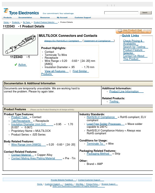
1123343-1 Product DetailsHome | Customer Support | Suppliers | Site Map | Privacy Policy | Browser Support© 2008 Tyco Electronics Corporation All Rights Reserved SearchProducts Documentation Resources My Account Customer Support Home > Products > By Type > Product Feature Selector > Product Details1123343-1Active MULTILOCK Connectors and ContactsAlways EU RoHS/ELV Compliant (Statement of Compliance)Product Highlights:?Contact?Terminate To Wire?Receptacle?Wire Range = 0.20-0.60²[24-20] mm[AWG]?Insulation Diameter = .95 -1.70 mmView all Features | Find SimilarProductsCheck Pricing &AvailabilitySearch for ToolingProduct FeatureSelectorContact Us AboutThis ProductQuick LinksDocumentation & Additional InformationDocuments are temporarily unavailable. We are working hard to correct the problem. Please try again later.Additional Information:?Product Line InformationRelated Products:?ToolingProduct Features (Please use the Product Drawing for all design activity)Product Type Features:?Product Type = Contact?Tab/Receptacle = Receptacle?Insulation Diameter (mm [in]) = 0.95 – 1.70[0.037 –0.067]?Proprietary Name = MULTILOCK?Product Series = .025 SeriesBody Related Features:?Wire Range (mm [AWG]) = 0.20-0.60²[24-20] Contact Related Features:?Contact Material = Copper Alloy?Contact Mating Area Plating Material = Pre-Tin Industry Standards:?RoHS/ELV Compliance = RoHS compliant, ELVcompliant?Lead Free Solder Processes = Wave soldercapable to 240°C?RoHS/ELV Compliance History = Always wasRoHS compliantConditions for Usage:?Terminate To = WirePackaging Related Features:?Packaging Method = StripOther:?Brand = AMPProvide Website Feedback | Contact Customer Support。
7413中文资料

100
VDS VGS RG
RD D.U.T.
10V
Pulse Width ≤ 1 µs Duty Factor ≤ 0.1 %
+-VDD
Fig 10a. Switching Time Test Circuit
VDS 90%
10% VGS
td(on) tr
td(off) tf
Fig 10b. Switching Time Waveforms
tr td(off) tf Ciss
Rise Time Turn-Off Delay Time Fall Time Input Capacitance
––– 8.0 ––– ns ID = 7.2A
––– 35 –––
RG = 6.2Ω
––– 14 –––
VGS = 10V
––– 1670 –––
Benefits
l Low Gate to Drain Charge to Reduce
S
1
Switching Losses
l Fully Characterized Capacitance Including S 2
AA
8
D
7
D
Effective COSS to Simplify Design, (See
Max. 12 9.6 96 2.5 0.02 ± 20 1.0
-55 to + 150
300 (1.6mm from case )
Units
A
W W/°C
V V/ns
°C
Thermal Resistance
Symbol RθJL RθJA
Parameter Junction-to-Drain Lead Junction-to-Ambient
7443资料
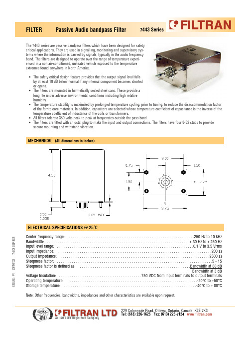
ELECTRICAL SPECIFICATIONS @ 25˚C
Center frequency range: . . . . . . . . . . . . . . . . . . . . . . . . . . . . . . . . . . . . . . . . . . . . . . . . . . . . . . . . . . .250 Hz to 10 kHz Bandwidth: . . . . . . . . . . . . . . . . . . . . . . . . . . . . . . . . . . . . . . . . . . . . . . . . . . . . . . . . . . . . . . . . . . .± 30 Hz to ± 250 Hz Input level range: . . . . . . . . . . . . . . . . . . . . . . . . . . . . . . . . . . . . . . . . . . . . . . . . . . . . . . . . . . . . . . . .0.1 V to 3.5 Vrms Input Impedance: . . . . . . . . . . . . . . . . . . . . . . . . . . . . . . . . . . . . . . . . . . . . . . . . . . . . . . . . . . . . . . . . . . . . . . . .200 Ω Output Impedance: . . . . . . . . . . . . . . . . . . . . . . . . . . . . . . . . . . . . . . . . . . . . . . . . . . . . . . . . . . . . . . . . . . . . . .2500 Ω Steepness factor: . . . . . . . . . . . . . . . . . . . . . . . . . . . . . . . . . . . . . . . . . . . . . . . . . . . . . . . . . . . . . . . . . . . . . . . . .5 - 15 Steepness factor is defined as: . . . . . . . . . . . . . . . . . . . . . . . . . . . . . . . . . . . . . . . . . . . . . . . . . . . .Bandwidth at 60 dB Bandwidth at 3 dB Voltage Insulation: . . . . . . . . . . . . . . . . . . . . . . . . . . . . . . . . . . . . . . .750 VDC from input terminals to output terminals Operating temperature: . . . . . . . . . . . . . . . . . . . . . . . . . . . . . . . . . . . . . . . . . . . . . . . . . . . . . . . . . . . . .-20°C to +50°C Storage temperature: . . . . . . . . . . . . . . . . . . . . . . . . . . . . . . . . . . . . . . . . . . . . . . . . . . . . . . . . . . . . . .-40°C to + 80°C
ISBN号——精选推荐

信息系统工程造价指导书 四六级英语动词搭配熟巧必备 你在营销上最可能犯的 101 个错误 设计与生存 税收理论与实践 品味乌龙茶 四季食疗与养生 思想营销——中国十大职业营销人求诸 子实战笔录 家常菜 1001 样 一生的感悟 赔钱时代 国务院关于预防煤矿生产安全事故的特 别规定释义 先做关系 后做销售 内部审计规范精要与案例分析 城市燃气:欧盟的管理体制和中国的改革
新《审计法》释解与实务指导
26.00 2006-03
2006 中国房地产市场展望 终极感悟:关于亲情 领导力
298.00 2006-03 32.00 2006-03 60.00 2006-02
作者 南国嘉木 [美]戴斯勒 南国嘉木 南国嘉木编 著 蔺丰奇 李三喜编著 [美]格里芬 宋学军编著 吴宝森著 古月轩编 裴淑红遍著 罗树忠著 高铁生 郭 冬乐主编 付广军主编 付广军主编 付广军主编
7-80155-960-6/F·638 7-80155-945-2/TS·6 7-80155-939-8/TS·3
债券市场创新理论与实务 泡杯好红茶 绿茶飘香
7-80155-949-5/F·633 保险诚信读本
25.00 2006-02 23.00 2006-02 25.00 2006-02
22.00 2006-02 30.00 2006-02
“十五”计划回顾与“十一五”规划展望 转轨经济中的审计:理论与实务 物资采购审计精要与案例分析
7-80155-982-7/G·42 7-80155-966-5/H·10 7-80155-901-0/F·595 7-80155-950-9/F·637 7-80155-958-4/F·636 7-80155-946-0/TS·7 7-80155-983-5/R·8
1827279中文资料
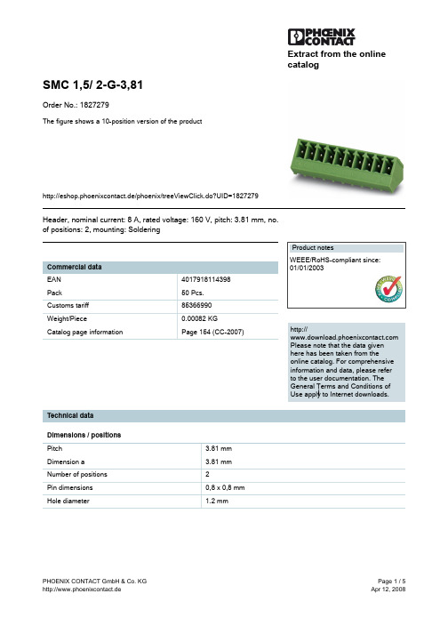
Extract from the onlinecatalogSMC 1,5/ 2-G-3,81Order No.: 1827279The figure shows a 10-position version of the producthttp://eshop.phoenixcontact.de/phoenix/treeViewClick.do?UID=1827279Header, nominal current: 8 A, rated voltage: 160 V, pitch: 3.81 mm, no. of positions: 2, mounting: Solderinghttp://Please note that the data givenhere has been taken from theonline catalog. For comprehensiveinformation and data, please referto the user documentation. TheGeneral Terms and Conditions ofUse apply to Internet downloads. Technical dataDimensions / positionsPitch 3.81 mmDimension a 3.81 mmNumber of positions2Pin dimensions0,8 x 0,8 mmHole diameter 1.2 mmTechnical dataInsulating material group IRated surge voltage (III/3) 2.5 kVRated surge voltage (III/2) 2.5 kVRated surge voltage (II/2) 2.5 kVRated voltage (III/2)160 VRated voltage (II/2)320 VConnection in acc. with standard EN-VDENominal current I N8 ANominal voltage U N160 VMaximum load current8 AInsulating material PAInflammability class acc. to UL 94V0Certificates / ApprovalsCSANominal voltage U N300 VNominal current I N8 ACULNominal voltage U N300 VNominal current I N8 AULNominal voltage U N300 VNominal current I N8 ACertification CB, CSA, CUL, GOST, UL, VDE-PZIAccessoriesItem Designation DescriptionMarking0804109SK 3,81/2,8:FORTL.ZAHLEN Marker card, printed horizontally, self-adhesive, 10-section markerstrip, 14 identical decades marked 1-10, 11-20 etc. up to 91-(99)100, sufficient for 140 terminal blocksPlug/Adapter1734634CP-MSTB Coding profile, is inserted into the slot on the plug or invertedheader, red insulating materialAdditional productsItem Designation DescriptionGeneral1851041FK-MCP 1,5/ 2-ST-3,81Plug component, nominal current: 8 A, rated voltage: 160 V, pitch:3.81 mm, no. of positions: 2, type of connection: Spring-cageconnection1850660FRONT-MC 1,5/ 2-ST-3,81Plug component, nominal current: 8 A, rated voltage: 160 V, pitch:3.81 mm, no. of positions: 2, type of connection: Screw connection 1862577IMC 1,5/ 2-G-3,81Header, nominal current: 8 A, rated voltage: 160 V, pitch: 3.81mm, no. of positions: 2, mounting: Soldering1875425IMCV 1,5/ 2-G-3,81Header, nominal current: 8 A, rated voltage: 160 V, pitch: 3.81mm, no. of positions: 2, mounting: Soldering1803578MC 1,5/ 2-ST-3,81Plug component, nominal current: 8 A, rated voltage: 160 V, pitch:3.81 mm, no. of positions: 2, type of connection: Screw connection 1852176MCC 1/ 2-STZ-3,81Plug component, nominal current: 8 A, rated voltage: 160 V, pitch:3.81 mm, no. of positions: 2, type of connection: Crimp connection 1827127MCVR 1,5/ 2-ST-3,81Plug component, nominal current: 8 A, rated voltage: 160 V, pitch:3.81 mm, no. of positions: 2, type of connection: Screw connection 1826979MCVW 1,5/ 2-ST-3,81Plug component, nominal current: 8 A, rated voltage: 160 V, pitch:3.81 mm, no. of positions: 2, type of connection: Screw connection 1897393QC 0,5/ 2-ST-3,81Plug, nominal current: 6 A, rated voltage: 320 V, pitch: 3.81mm, number of positions: 2, connection method: Insulationdisplacement connection QUICKONDrawingsDrilling diagramDimensioned drawingAddressPHOENIX CONTACT GmbH & Co. KGFlachsmarktstr. 832825 Blomberg,GermanyPhone +49 5235 3 00Fax +49 5235 3 41200http://www.phoenixcontact.de© 2008 Phoenix ContactTechnical modifications reserved;。
国内出版社ISBN对照表

国内出版社ISBN对照表国内图书10位ISBN组成:7-A-B-C国内图书13位ISBN组成:978-7-A-B-D说明:978:代表图书7:中国大陆A:出版社代号B:出版社的图书编号C和D:ISBN校验码,10位与13位ISBN算法不同European Artide Numbering(欧洲物品编码的缩写) 13位的ISBN 其实是EAN-13如果A部分越短,说明出版社越大, 因为A和B共8位7-80000-xxx-y 印刷工业出版社7-80003-xxx-y 万国学术出版社7-80007-xxx-y 中国摄影出版社7-80009-xxx-y 时事出版社7-80012-xxx-y 中国工商出版社7-80017-xxx-y 长城出版社7-80024-xxx-y 中国画报出版社7-80031-xxx-y 中华地图学社7-80040-xxx-y 昆仑出版社7-80043-xxx-y 石化出版社7-80047-xxx-y 紫禁城出版社7-80057-xxx-y 中国藏学出版社7-80063-xxx-y 长虹出版公司7-80065-xxx-y 人民中国出版社7-80069-xxx-y 中国民族摄影艺术出版社7-80078-xxx-y 中国民主法制出版社7-80080-xxx-y 群言出版社7-80083-xxx-y 中国法制出版社7-80084-xxx-y 金城出版社7-80087-xxx-y 中国发展出版社7-80097-xxx-y 中国大地出版社7-80098-xxx-y 党建读物出版社7-80099-xxx-y 中国三峡出版社7-80103-xxx-y 商务印书馆国际有限公司7-80104-xxx-y 星球地图出版社7-80106-xxx-y 线装书局7-80107-xxx-y 中国方正出版社7-80108-xxx-y 西苑出版社7-80109-xxx-y 中央编译出版社7-80110-xxx-y 中国民航出版社7-80112-xxx-y 民主与建设出版社7-80115-xxx-y 当代世界出版社7-80116-xxx-y 学习出版社7-80117-xxx-y 中国税务出版社7-80120-xxx-y 中国华侨出版社7-80121-xxx-y 军事医学科学出版社7-80123-xxx-y 宗教文化出版社7-80128-xxx-y 中国言实出版社7-80129-xxx-y 华乐出版社7-80130-xxx-y 团结出版社7-80137-xxx-y 军事科学出版社7-80138-xxx-y 海豚出版社7-80140-xxx-y 国家行政学院出版社7-80141-xxx-y 台海出版社7-80142-xxx-y 华艺出版社7-80144-xxx-y 中国宇航出版社7-80145-xxx-y 光明日报出版社7-80148-xxx-y 新星出版社7-80150-xxx-y 军事谊文出版社7-80151-xxx-y 海潮出版社7-80152-xxx-y 黄河出版社7-80153-xxx-y 人民日报出版社7-80155-xxx-y 中国市场出版社7-80156-xxx-y 中国中医药出版社7-80158-xxx-y 蓝天出版社7-80159-xxx-y 中国建材工业出版社7-80161-xxx-y 人民法院出版社7-80162-xxx-y 经济管理出版社7-80163-xxx-y 中国环境科学出版社7-80164-xxx-y 中国石化出版社7-80165-xxx-y 中国海关出版社7-80166-xxx-y 中国档案出版社7-80167-xxx-y 中国农业科学技术出版社7-80168-xxx-y 研究出版社7-80169-xxx-y 中国时代经济出版社7-80170-xxx-y 当代中国出版社7-80171-xxx-y 大众文艺出版社7-80172-xxx-y 兵器工业出版社7-80173-xxx-y 国际文化出版公司7-80175-xxx-y 中国长安出版社7-80176-xxx-y 人民武警出版社7-80177-xxx-y 中国计划出版社7-80178-xxx-y 华龄出版社7-80179-xxx-y 中国致公出版社7-80180-xxx-y 经济日报出版社7-80181-xxx-y 中国对外经济贸易大学出版社7-80183-xxx-y 航空工业出版社7-80184-xxx-y 语文出版社7-80185-xxx-y 中国检察出版社7-80186-xxx-y 东方出版中心7-80187-xxx-y 新世界出版社7-80188-xxx-y 现代出版社7-80189-xxx-y 中国人事出版社7-80190-xxx-y 社会科学文献出版社7-80191-xxx-y 龙门书局7-80192-xxx-y 方志出版社7-80193-xxx-y 中华工商联合出版社7-80194-xxx-y 人民军医出版社7-80195-xxx-y 九州出版社7-80196-xxx-y 现代教育出版社7-80197-xxx-y 企业管理出版社7-80198-xxx-y 知识产权出版社7-80199-xxx-y 中共党史出版社7-80200-xxx-y 华语教学出版社7-80201-xxx-y 中国和平出版社7-80202-xxx-y 中国人口出版社7-80203-xxx-y 中国妇女出版社7-80204-xxx-y 长征出版社7-80205-xxx-y 开明出版社7-80501-xxx-y 北京美术摄影出版社7-80503-xxx-y 天津杨柳青画社7-80516-xxx-y 福建省地图出版社7-80517-xxx-y 西泠出版社7-80518-xxx-y 浙江古籍出版社7-80522-xxx-y 广东省地图出版社7-80525-xxx-y 德宏民族出版社7-80526-xxx-y 北京工艺美术出版社7-80529-xxx-y 哈尔滨地图出版社7-80532-xxx-y 山东省地图出版社7-80550-xxx-y 书海出版社7-80552-xxx-y 湖南地图出版社7-80554-xxx-y 文津出版社7-80587-xxx-y 敦煌文艺出版社7-80588-xxx-y 甘肃人民美术出版社7-80589-xxx-y 西藏藏文古籍出版社7-80593-xxx-y 同心出版社7-80595-xxx-y 远方出版社7-80596-xxx-y 宁夏人民教育出版社7-80597-xxx-y 海风出版社7-80598-xxx-y 山西古籍出版社7-80600-xxx-y 京华出版社7-80601-xxx-y 万卷出版公司7-80602-xxx-y 宁波出版社7-80606-xxx-y 吉林摄影出版社7-80608-xxx-y 甘肃文化出版社7-80612-xxx-y 大连出版社7-80614-xxx-y 南京出版社7-80620-xxx-y 宁夏少年儿童出版社7-80621-xxx-y 黄河水利出版社7-80623-xxx-y 河南文艺出版社7-80624-xxx-y 天地出版社7-80628-xxx-y 三秦出版社7-80632-xxx-y 广东经济出版社7-80633-xxx-y 杭州出版社7-80634-xxx-y 泰山出版社7-80636-xxx-y 山西经济出版社7-80640-xxx-y 海峡文艺出版社7-80641-xxx-y 中原农民出版社7-80642-xxx-y 山东友谊出版社7-80643-xxx-y 江苏古籍出版社7-80644-xxx-y 辽宁民族出版社7-80646-xxx-y 上海文化出版社7-80647-xxx-y 百花洲文艺出版社7-80650-xxx-y 贵州教育出版社7-80651-xxx-y 羊城晚报出版社7-80652-xxx-y 南方日报出版社7-80653-xxx-y 广东旅游出版社7-80655-xxx-y 广州出版社7-80657-xxx-y 译林出版社7-80658-xxx-y 新疆美术摄影出版社7-80659-xxx-y 巴蜀书社7-80662-xxx-y 贵州科技出版社7-80663-xxx-y 中国书店7-80664-xxx-y 长春出版社7-80665-xxx-y 岳麓书社7-80666-xxx-y 广西科学技术出版社7-80667-xxx-y 上海音乐出版社7-80668-xxx-y 学林出版社7-80670-xxx-y 西安地图出版社7-80671-xxx-y 鹭江出版社7-80672-xxx-y 上海书画出版社7-80673-xxx-y 花山文艺出版社7-80674-xxx-y 广西美术出版社7-80675-xxx-y 内蒙古文化出版社7-80676-xxx-y 文汇出版社7-80678-xxx-y 上海书店7-80679-xxx-y 接力出版社7-80680-xxx-y 太白文艺出版社7-80681-xxx-y 上海社会科学院出版社7-80682-xxx-y 四川辞书出版社7-80683-xxx-y 文心出版社7-80685-xxx-y 上海画报出版社7-80686-xxx-y 浙江摄影出版社7-80687-xxx-y 白山出版社7-80688-xxx-y 天津社会科学院出版社7-80689-xxx-y 朝华出版社7-80689-xxx-y 珠海出版社7-80690-xxx-y 江西美术出版社7-80691-xxx-y 海潮摄影艺术出版社7-80692-xxx-y 上海音乐学院出版社7-80693-xxx-y 新疆科学技术出版社7-80694-xxx-y 广陵书社7-80695-xxx-y 云南美术出版社7-80696-xxx-y 天津古籍出版社7-80697-xxx-y 海天出版社7-80698-xxx-y 延边人民出版社7-80699-xxx-y 哈尔滨出版社7-80700-xxx-y 三环出版社7-80701-xxx-y 南方出版社7-80702-xxx-y 吉林文史出版社7-80703-xxx-y 百家出版社7-80704-xxx-y 成都地图出版社7-80705-xxx-y 成都时代出版社7-80706-xxx-y 上海远东出版社7-80707-xxx-y 黄山书社7-80708-xxx-y 长江出版社7-80709-xxx-y 深圳报业集团出版社7-80710-xxx-y 济南出版社7-80711-xxx-y 辽海出版社7-80712-xxx-y 西安出版社7-80713-xxx-y 山东画报出版社7-81010-xxx-y 上海中医药大学出版社7-81030-xxx-y 武汉测绘科技大学出版社7-81036-xxx-y 汕头大学出版社7-81038-xxx-y 东华大学出版社7-81042-xxx-y 辽宁师范大学出版社7-81048-xxx-y 郑州大学出版社7-81052-xxx-y 安徽大学出版社7-81053-xxx-y 湖南大学出版社7-81056-xxx-y 中央民族大学出版社7-81057-xxx-y 西南交通大学出版社7-81058-xxx-y 上海大学出版社7-81060-xxx-y 第二军医大学出版社7-81061-xxx-y 中南大学出版社7-81063-xxx-y 武汉水利电力大学出版社7-81064-xxx-y 首都师范大学出版社7-81066-xxx-y 中国农业大学出版社7-81067-xxx-y 中国海洋大学出版社7-81068-xxx-y 云南大学出版社7-81070-xxx-y 中国矿业大学出版社7-81071-xxx-y 北京大学医学出版社7-81072-xxx-y 中国协和医科大学出版社7-81073-xxx-y 哈尔滨工程大学出版社7-81074-xxx-y 内蒙古大学出版社7-81075-xxx-y 江西高校出版社7-81076-xxx-y 东北林业大学出版社7-81077-xxx-y 北京航空航天大学出版社7-81078-xxx-y 对外经济贸易大学出版社7-81079-xxx-y 暨南大学出版社7-81081-xxx-y 湖南师范大学出版社7-81082-xxx-y 北京交通大学出版社7-81083-xxx-y 中国美术学院出版社7-81084-xxx-y 东北财经大学出版社7-81085-xxx-y 北京广播学院出版社7-81086-xxx-y 第四军医大学出版社7-81087-xxx-y 中国人民公安大学出版社7-81088-xxx-y 西南财经大学出版社7-81089-xxx-y 东南大学出版社7-81090-xxx-y 苏州大学出版社7-81091-xxx-y 河南大学出版社7-81092-xxx-y 西北农林科技大学出版社7-81093-xxx-y 合肥工业大学出版社7-81094-xxx-y 电子科技大学出版社7-81095-xxx-y 上海外语教育出版社7-81096-xxx-y 中央音乐学院出版社7-81097-xxx-y 河北大学出版社7-81098-xxx-y 上海财经大学出版社7-81099-xxx-y 国防科技大学出版社7-81100-xxx-y 北京体育大学出版社7-81101-xxx-y 南京师范大学出版社7-81102-xxx-y 东北大学出版社。
SLG7NT4192_DS_r011_05272013
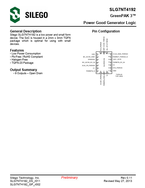
GreenPAK 3™Power Good Generator LogicGeneral Description Array Silego SLG7NT4192 is a low power and small formdevice. The SoC is housed in a 2mm x 3mm TQFNpackage which is optimal for using with smalldevices.Features• Low Power Consumption• Pb-Free / RoHS Compliant• Halogen-Free• TQFN-20 PackageOutput Summary• 9 Outputs – Open DrainPower Good Generator Logic Block DiagramPower Good Generator Logic Pin ConfigurationPin # Pin Name Type Pin Description1 VDD PWR Supply Voltage2 BC_ACOK_DSW Input Digital in without Schmitt trigger3 DPWROK Output Open Drain4 BC_ACOK_EC_IN Output Open Drain5 SUS_VR_PWRGD Input Digital in without Schmitt trigger6 V1 Input Analog Input7 PWRBTN_N Input Digital in without Schmitt trigger8 VCCST_PWRGD Output Open Drain9 PWRBTN_DSW_N Output Open Drain10 V2 Input Analog Input11 GND GND Ground12 SYS_PWROK Output Open Drain13 V3 Input Analog input14 PWRBTN_EC_IN Output Open Drain15 VBAT_MON Input Analog input16 RSMRST_PWRGD_N Output Open Drain17 V3.3A_DSW_PWRGD Input Digital in without Schmitt trigger18 ALL_SYS_PWRGD Output Open Drain19 DDR_VCCIO_PWRGD Input Digital in without Schmitt trigger20 PCH_PWROK Output Open DrainOrdering InformationPart Number Package TypeSLG7NT4192V V=TQFN-20SLG7NT4192VTR TQFN-20 – Tape and Reel (3k units)Power Good Generator Logic Absolute Maximum ConditionsParameter Min. Max. UnitV HIGH to GND -0.3 7 VVoltage at input pins -0.3 7 VCurrent at input pin -1.0 1.0 mAStorage temperature range -65 150 °CJunction temperature -- 150 °CElectrical Characteristics(@ 25°C, unless otherwise stated)Symbol Parameter Condition/Note Min. Typ. Max. Unit V DD Supply Voltage 3.135 3.3 3.465 V T A Operating Temperature -40 25 85 °CI Q Quiescent Current Static inputs and outputs -- 85 -- μAV IH HIGH-Level Input Voltage Logic Input 1.8 -- -- -- V IL LOW-Level Input Voltage Logic Input -- -- 1.3 VI IH HIGH-Level Input Current Logic Input Pins; V IN =3.3V -1.0 -- 1.0 μAI IL LOW-Level Input Current Logic Input Pins; V IN =0V -1.0 -- 1.0 μAV OL LOW-Level Output Voltage Open Drain,I OL = 3 mA, 1X Driver-- 0.080 0.15 VI OL LOW-Level Output Current Open Drain, V OL = 0.4 V, 1X Driver 7.3 12 -- mAV O Maximal Voltage Applied toany PIN in High-ImpedanceState-- -- VDD VV ACMP0 Analog Comparator ReferenceVoltageIncluding ACMP0 voltage reference T.B.D. 950 T.B.D. mVV ACMP1 Analog Comparator ReferenceVoltageIncluding ACMP1 voltage reference T.B.D. 950 T.B.D. mVV ACMP2Analog Comparator ReferenceVoltageIncluding ACMP2 voltage reference T.B.D. 950 T.B.D. mVV ACMP3Analog Comparator ReferenceVoltageIncluding ACMP3 voltage reference T.B.D. 950 T.B.D. mVV HYST Analog Comparator HysteresisVoltageACMP0, ACMP1, ACMP2, ACMP3 T.B.D. 50 T.B.D. mVV OFFSET Analog Comparator OffsetVoltageACMP0, ACMP1, ACMP2, ACMP3 -- ±5 -- mVT DLY0Delay0 Time T.B.D. 2.5 T.B.D. msPower Good Generator LogicPower Good Generator Logic SLG7NT4192 Functionality WaveformsInputs:D0 – Pin #15 (VBAT_MON)D1 – Pin #17 (V3.3A_DSW_PWRGD)D2 – Pin #7 (PWRBTN_N)D3 – Pin #6 (V1)D4 – Pin #10 (V2)D5 – Pin #13 (V3)D6 – Pin #2 (BC_ACOK_DSW)Outputs:D7 – Pin #3 (DPWROK) with external 5kΩ pull-up resistorD8 – Pin #16 (RSMRST_PWRGD_N) with external 5kΩ pull-up resistorD9 – Pin #14 (PWRBTN_EC_IN) with external 5kΩ pull-up resistorD10 – Pin #9 (PWRBTN_DSW_N) with external 5kΩ pull-up resistorD11 – Pin #8 (VCCST_PWRGD) with external 5kΩ pull-up resistorD12 – Pin #18 (ALL_SYS_PWRGD) with external 5kΩ pull-up resistorD13 – Pin #12 (SYS_PWROK) with external 5kΩ pull-up resistorD14 – Pin #20 (PCH_PWROK) with external 5kΩ pull-up resistorD15 – Pin #4 (BC_ACOK_EC_IN) with external 5kΩ pull-up resistor1. Chip functionality (Pin5 (SUS_VR_PWRGD), Pin19 (DDR_VCCIO_PWRGD) are always HIGH)Power Good Generator LogicPackage Top MarkingDatasheet Revision Programming Code NumberPart CodeRevisionDate 0.11 0205/27/2013Power Good Generator Logic Package Drawing and Dimensions20 Lead TQFN PackageJEDEC MO-220, Variation WCEEPower Good Generator LogicTape and Reel SpecificationPackage Type# of PinsNominal Package Size (mm)Max Units Reel & Hub Size(mm) Trailer A Leader BPocket (mm) per reelper boxPockets Length (mm) Pockets Length (mm)WidthPitchTQFN 20L2x3mm 0.4P Green20 2x3x0.75 3000 3000 178/60 42 168 42 168 8 4Carrier Tape Drawing and DimensionsPackageTypePocketBTMLength (mm)PocketBTM Width(mm)PocketDepth(mm) Index HolePitch(mm)Pocket Pitch (mm) Index Hole Diameter (mm)Index Hole to Tape Edge (mm) Index Hole to Pocket Center (mm)Tape Width (mm) A0B0K0P0P1D0EFWTQFN 20L 2x3mm 0.4P Green2.253.3 1.1 4 4 1.55 1.75 3.5 8Refer to EIA-481 SpecificationsRecommended Reflow Soldering ProfilePlease see IPC/JEDEC J-STD-020: latest revision for reflow profile based on package volume of 4.50 mm 3(nominal).More information can be found at .Power Good Generator Logic Datasheet Revision HistoryDate Version Change05/20/2013 0.1 New design05/27/2013 0.11 Updated designSLG7NT4192Power Good Generator LogicSLG7NT4192_DS_r011PreliminaryPage 11 11 Silego Website & SupportSilego Technology WebsiteSilego Technology provides online support via our website at /.This website is used as a means to make files and information easily available to customers.For more information regarding Silego Green products, please visit://///Products are also available for purchase directly from Silego at the Silego Online Store at /.Silego Technical SupportDatasheets and errata, application notes and example designs, user guides, and hardware support documents and the latest software releases are available at the Silego website or can be requested directly at info@ .For specific GreenPAK design or applications questions and support please send email requests to GreenPAK@Users of Silego products can receive assistance through several channels:Contact Your Local Sales RepresentativeCustomers can contact their local sales representative or field application engineer (FAE) for support. Local sales offices are also available to help customers. More information regarding your local representative is available at the Silego website or send a request to info@Contact Silego DirectlySilego can be contacted directly via e-mail at info@ or user submission form, located at the following URL: /Other InformationThe latest Silego Technology press releases, listing of seminars and events, listings of worldwide Silego Technology offices and representatives are all available at /THIS PRODUCT HAS BEEN DESIGNED AND QUALIFIED FOR THE CONSUMER MARKET. APPLICATIONS OR USES AS CRITICAL COMPONENTS IN LIFE SUPPORT DEVICES OR SYSTEMS ARE NOT AUTHORIZED. SILEGO TECHNOLOGY DOES NOT ASSUME ANY LIABILITY ARISING OUT OF SUCH APPLICATIONS OR USES OF ITS PRODUCTS. SILEGO TECHNOLOGY RESERVES THE RIGHT TO IMPROVE PRODUCT DESIGN, FUNCTIONS AND RELIABILITY WITHOUT NOTICE.。
34713资料

MCP1827中文资料

DS22001C_CN 第 6 页
2007 Microchip Technology Inc.
MCP1827/MCP1827S
交流 / 直流电气特性 (续)
电气特性:除非另外声明,否则 VIN = VOUT(MAX) + VDROPOUT(MAX) (注 1) , VR=1.8V (针对可调输出) , IOUT = 1 mA, CIN = COUT = 4.7 µF (X7R 陶瓷电容) , TA = +25°C。黑体数值适用于 -40°C 至 +125°C 的结温 TJ (注 7) 。 参数 电压稳定度 压差特性 电压差 电源正常指示特性 PWRGD 输入电压工作范围 VPWRGD_VIN 1.0 1.2 PWRGD 阈值电压 (参见 VOUT) VPWRGD_TH 89 90 PWRGD 阈值迟滞 PWRGD 输出低电压 PWRGD 泄漏电流 PWRGD 延迟 检测阈值到 PWRGD 有效的延时 关断输入 逻辑高电平输入 逻辑低电平输入 SHDN 输入泄漏电流 交流性能 SHDN 输出延时 输出噪声 TOR eN — 100 2.0 — µs µV/√Hz SHDN = GND 至 VIN VOUT = GND 至 95%VR IOUT = 200 mA, f = 1 kHz, COUT = 10 µF (X7R 陶瓷电 容) , VOUT = 2.5V VSHDN-HIGH VSHDN-LOW SHDNILK -0.1 ±0.001 45 15 +0.1 %VIN %VIN µA VIN = 2.3V 至 6.0V VIN = 2.3V 至 6.0V VIN = 6V, SHDN =VIN, SHDN = GND VPWRGD_HYS VPWRGD_L PWRGD_LK TPG TVDET-PWRGD 1.0 — — — — 92 92 2.0 0.2 1 200 200 95 94 3.0 0.4 — — — %VOUT V nA µs µs IPWRGD SINK = 1.2 mA, ADJ = 0V VPWRGD = VIN = 6.0V 上升延 RPULLUP = 10 kΩ VADJ 或 VOUT = VPWRGD_TH + 20 mV 至 VPWRGD_TH - 20 mV — — 6.0 6.0 %VOUT V TA = +25°C TA = -40°C 至 +125°C VIN < 2.3V, ISINK = 100 µA 下降沿 VOUT < 2.5V 固定输出,VOUT = 可调输出 VOUT >= 2.5V 固定输出 VIN-VOUT — 330 600 mV 注 5, IOUT = 1.5A, VIN(MIN) = 2.3V 符号 VOUT 最小值 VR - 2.5% 典型值 VR ±0.5% 最大值 VR + 2.5% 单位 V 注 2 测试条件
ISO 15378 中文版

0 引言0.1 通则此ISO标准识别了GMP原则和为适用于药品的初级包装材料(即内包装材料/直接接触药品包装材料,以下直接简称为药包材,Seconday packaging materials 为外包装材料/不直接接触药品的包装材料)的QMS的规定要求。
由于这些药包材直接接触药品,在生产和控制这些材料的组织内实现GMP原则对于患者使用药品时的安全性来说十分重要。
应用GMP 原则生产药包材,应确保达到药厂的需求。
此ISO标准是针对药包材的应用标准,同时也包含了ISO9001:2000的要求。
此ISO标准的布局规定如下:-1 正体字为直接从ISO9001:2000引用并未做改变的条款或子条款。
-2 斜体字为包含附件的有关直接的直接接触药品包装材料的GMP要求。
-3 条款3包含GMP术语和定义,并在括号中列出来源。
ISO 9001:2000,质量管理体系—要求0.1 通则采用QMS应当是组织的一项战略性决策。
一个组织QMS的设计和实施受不同需求、特定目标、所提供的产品、采用的过程、组织的规模和结构的影响。
统一的QMS结构或文件并不是本ISO标准的目的。
本ISO标准规定的QMS要求是对是对产品要求的补充。
“注”是帮助理解或者澄清有关要求的参考信息。
本ISO标准可用于组织内部和外部各方(包括认证机构)评价组织达到客户,法规和组织自身要求的能力。
在开发此ISO标准时已经考虑ISO9000和ISO9004中所阐明的质量管理原则。
此ISO标准关键目的是规定一个统一的针对药包材的要求,包括一些来源于药品GMP 生产和控制等方面的特殊要求。
0.2 过程方法本ISO标准鼓励在建立、实施质量管理体系和提高其有效性时采用过程方法,旨在通过以满足客户要求的方式来增加客户满意度。
为使组织有效运行,必须确认和管理众多相互关联的活动。
使用资源并实施管理,将输入转化为输出的一个活动,可被可视为一个过程。
通常一个过程的输出可以直接形成下一过程的输入。
744770133;中文规格书,Datasheet资料
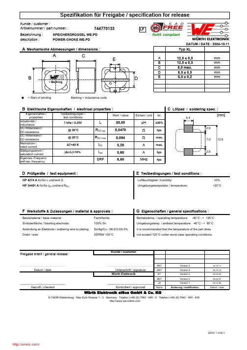
Bezeichnung :description := Start of winding Marking = Inductance code33% Umgebungstemperatur / temperature:+20°C100% SnMST 04-10-11MST 03-12-10RT 03-03-03MST02-03-27JH 00-12-06NameDatum / dateIt is recommended that the temperature of the part does not exceed 125°C under worst case operating conditions.Anbindung an Elektrode / soldering wire to plating:Sn/Ag/Cu - 96.5/3.0/0.5%Draht / wire:2SFBW 155°CUmgebungstemp. / ambient temperature: -40°C - + 85°C Freigabe erteilt / general release:Kunde / customerWürth Elektronik....................................................................................................................................................................Unterschrift / signature Ferrit/ferrite F Werkstoffe & Zulassungen / material & approvals :G Eigenschaften / general specifications :D Prüfgeräte / test equipment :E Testbedingungen / test conditions :Basismaterial / base material:Betriebstemp. / operating temperature: -40°C - + 125°C D-74638 Waldenburg · Max-Eyth-Strasse 1 - 3 · Germany · Telefon (+49) (0) 7942 - 945 - 0 · Telefax (+49) (0) 7942 - 945 - 400Geprüft / checked ..........................................................................................................................Kontrolliert / approvedWürth Elektronik eiSos GmbH & Co. KG744770133SPEICHERDROSSEL WE-PDPOWER-CHOKE WE-PDArtikelnummer / part number : Luftfeuchtigkeit / humidity:HP 4274 A für/for L und/and Q HP 34401 A für/for I DC und/and R DCÄnderung / modificationVersion 1Version 2Version 3Version 4Version 5 Datum / dateEndoberfläche / finishing electrode:• MarkingRoHS compliantLFdescription :MST 04-10-11MST 03-12-10RT 03-03-03MST02-03-27JH 00-12-06NameDatum / dateH Induktivitätskurve / Inductance curve :POWER-CHOKE WE-PDDATUM / DATE : 2004-10-11Kontrolliert / approvedDatum / dateUnterschrift / signature Würth ElektronikWürth Elektronik eiSos GmbH & Co. KGD-74638 Waldenburg · Max-Eyth-Strasse 1 - 3 · Germany · Telefon (+49) (0) 7942 - 945 - 0 · Telefax (+49) (0) 7942 - 945 - 400Freigabe erteilt / general release:Kunde / customer..................................................................................................................................................................................................................................................................................Geprüft / checked Version 4Version 5Änderung / modificationVersion 1Version 2Version 3a 330,0± 0,5mmb 20,20± 0,2mm+ 0,5- 1,0d 100,0± 0,2mmMST 04-10-11MST 03-12-10RT 03-03-03MST02-03-27JH 00-12-06NameDatum / dateRollenspezifikation / Reel specification:Freigabe erteilt / general release:Kunde / customerc 13,00mm....................................................................................................................................................................Datum / dateUnterschrift / signature Würth Elektronik..........................................................................................................................Würth Elektronik eiSos GmbH & Co. KGGeprüft / checked Kontrolliert / approvedD-74638 Waldenburg · Max-Eyth-Strasse 1 - 3 · Germany · Telefon (+49) (0) 7942 - 945 - 0 · Telefax (+49) (0) 7942 - 945 - 400Änderung / modificationVersion 1Version 2Version 3Version 4Version 5The force for tearing off cover tape is 10 to 130 grams in arrow direction165 to 180°feeding directionThis electronic component is designed and developed with the intention for use in general electronics equipments. Before incorporating the components into any equipments in the field such as aerospace, aviation, nuclear control, submarine, transportation, (automotive control, train control, ship control), transportation signal, disaster prevention, medical, public information network etc. where higher safety and reliability are especially required or if there is possibility of direct damage or injury to human body. In addition, even electronic component in general electronic equipments, when used in electrical circuits that require high safety, reliability functions or performance, the sufficient reliability evaluation-check for the safety must be performed before use. It is essential to give consideration when to install a protective circuit at the design stage.分销商库存信息: WURTH-ELECTRONICS 744770133。
1827540-1资料
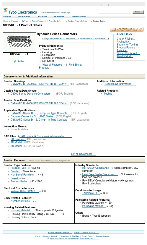
1827540-1 Product DetailsHome | Customer Support | Suppliers | Site Map | Privacy Policy | Browser Support© 2008 Tyco Electronics Corporation All Rights Reserved SearchProducts Documentation Resources My Account Customer SupportHome > Products > By Type > Power Products (>10 Amps/Contact) > Product Feature Selector > Product Details1827540-1Active Dynamic Series ConnectorsAlways EU RoHS/ELV Compliant (Statement of Compliance)Product Highlights:?Terminate To Wire?Housing?Receptacle?Number of Positions = 48?Not KeyedView all Features | Find SimilarProductsCheck Pricing &AvailabilitySearch for ToolingProduct FeatureSelectorContact Us AboutThis ProductQuick LinksDocumentation & Additional InformationProduct Drawings:?DYNAMIC D-2600 SERIES HYBRID 48P CONN(TIF, Japanese)Catalog Pages/Data Sheets:?D2000 Series Dynamic Connectors(PDF, English)Product Specifications:?DYNAMIC D-2600 SERIES HYBRID 48P CONN(PDF, Japanese)Application Specifications:?DYNAMIC Series D-3, Crimp-in Type Contacts(PDF, English)?Dynamic Connector D-2000 Series(PDF, English)?DYNAMIC Series D-3, Crimp-in Type Contacts(TIF, Japanese)Instruction Sheets:?None AvailableCAD Files: (CAD Format & Compression Information)?2D Drawing (DXF, Version A)?3D Model (IGES, Version A)?3D Model (STEP, Version A)List all Documents Additional Information:?Product Line InformationRelated Products:?ToolingProduct Features (Please use the Product Drawing for all design activity)Product Type Features:?Product Type = Housing?Gender = Receptacle?Number of Positions = 48?Keyed = No?Product Series = D-2600Electrical Characteristics:?Voltage Rating (VAC) = 600Body Related Features:?Number of Rows = 3Housing Related Features:?Housing Material = Thermoplastic Polyester ?Housing Flammability Rating = UL 94V-0 ?Housing Color = Black Industry Standards:?RoHS/ELV Compliance = RoHS compliant, ELVcompliant?Lead Free Solder Processes = Not relevant forlead free process?RoHS/ELV Compliance History = Always wasRoHS compliantConditions for Usage:?Terminate To = WirePackaging Related Features:?Packaging Quantity = 150?Packaging Method = BagOther:?Brand = Tyco ElectronicsProvide Website Feedback | Contact Customer Support。
6339447-7资料
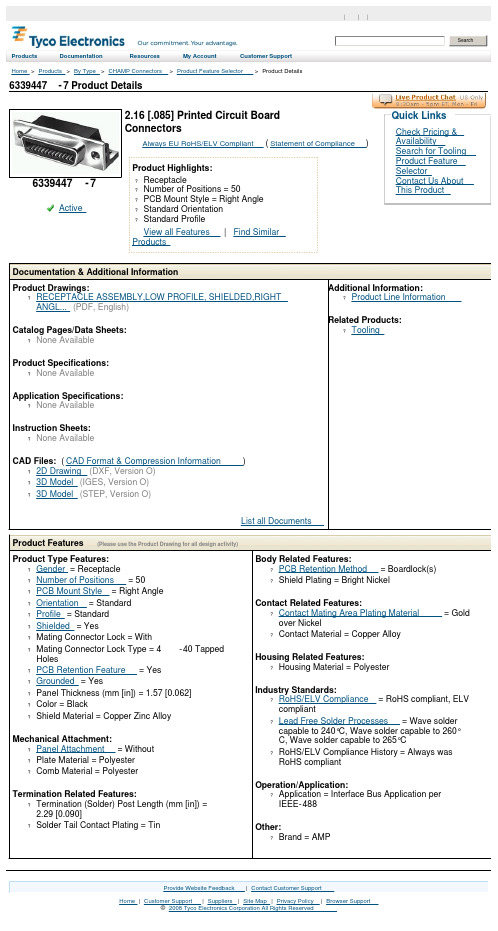
6339447-7 Product DetailsHome | Customer Support | Suppliers | Site Map | Privacy Policy | Browser Support© 2008 Tyco Electronics Corporation All Rights Reserved SearchProducts Documentation Resources My Account Customer Support Home > Products > By Type > CHAMP Connectors > Product Feature Selector > Product Details6339447-7Active 2.16 [.085] Printed Circuit BoardConnectorsAlways EU RoHS/ELV Compliant (Statement of Compliance)Product Highlights:?Receptacle?Number of Positions = 50?PCB Mount Style = Right Angle?Standard Orientation?Standard ProfileView all Features | Find SimilarProductsCheck Pricing &AvailabilitySearch for ToolingProduct FeatureSelectorContact Us AboutThis ProductQuick LinksDocumentation & Additional InformationProduct Drawings:?RECEPTACLE ASSEMBLY,LOW PROFILE, SHIELDED,RIGHTANGL...(PDF, English)Catalog Pages/Data Sheets:?None AvailableProduct Specifications:?None AvailableApplication Specifications:?None AvailableInstruction Sheets:?None AvailableCAD Files: (CAD Format & Compression Information)?2D Drawing (DXF, Version O)?3D Model (IGES, Version O)?3D Model (STEP, Version O)List all Documents Additional Information:?Product Line InformationRelated Products:?ToolingProduct Features (Please use the Product Drawing for all design activity)Product Type Features:?Gender = Receptacle?Number of Positions = 50?PCB Mount Style = Right Angle?Orientation = Standard?Profile = Standard?Shielded = Yes?Mating Connector Lock = With?Mating Connector Lock Type = 4-40 TappedHoles?PCB Retention Feature = Yes?Grounded = Yes?Panel Thickness (mm [in]) = 1.57 [0.062]?Color = Black?Shield Material = Copper Zinc Alloy Mechanical Attachment:?Panel Attachment = Without?Plate Material = Polyester?Comb Material = PolyesterTermination Related Features:?Termination (Solder) Post Length (mm [in]) =2.29 [0.090]?Solder Tail Contact Plating = Tin Body Related Features:?PCB Retention Method = Boardlock(s)?Shield Plating = Bright NickelContact Related Features:?Contact Mating Area Plating Material = Goldover Nickel?Contact Material = Copper AlloyHousing Related Features:?Housing Material = PolyesterIndustry Standards:?RoHS/ELV Compliance = RoHS compliant, ELVcompliant?Lead Free Solder Processes = Wave soldercapable to 240°C, Wave solder capable to 260°C, Wave solder capable to 265°C?RoHS/ELV Compliance History = Always wasRoHS compliantOperation/Application:?Application = Interface Bus Application perIEEE-488Other:?Brand = AMPProvide Website Feedback | Contact Customer Support。
VI-882477资料
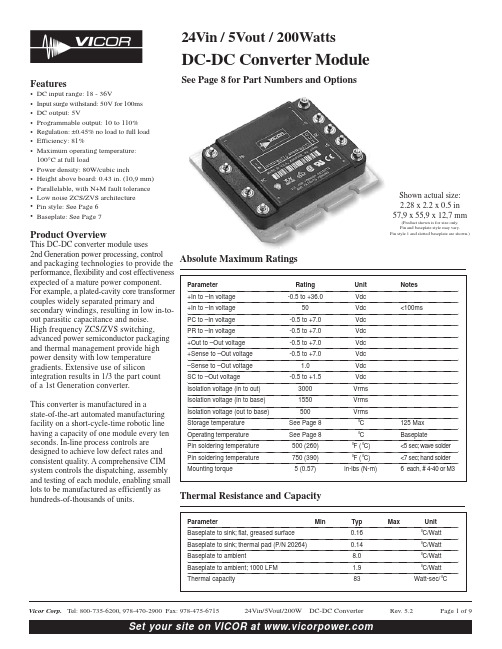
Shown actual size:2.28 x 2.2 x 0.5 in 57,9 x 55,9 x 12,7 mm(Product shown is for size only. Pin and baseplate style may vary.Pin style 1 and slotted baseplate are shown.)4Absolute Maximum RatingsThermal Resistance and Capacity24Vin /5Vout / 200WattsDC-DC Converter ModuleSee Page 8 for Part Numbers and OptionsFeatures•DC input range: 18- 36V•Input surge withstand: 50V for 100ms •DC output: 5V•Programmable output: 10 to 110%•Regulation: ±0.45% no load to full load •Efficiency: 81%•Maximum operating temperature: 100°C at full load•Power density: 80W/cubic inch•Height above board: 0.43 in. (10,9 mm)•Parallelable, with N+M fault tolerance •Low noise ZCS/ZVS architecture •Pin style: See Page 6• Baseplate: See Page 7Product OverviewThis DC-DC converter module uses 2nd Generation power processing, control and packaging technologies to provide the performance, flexibility and cost effectiveness expected of a mature power component. For example, a plated-cavity core transformer couples widely separated primary andsecondary windings, resulting in low in-to-out parasitic capacitance and noise. High frequency ZCS/ZVS switching,advanced power semiconductor packaging and thermal management provide high power density with low temperature gradients. Extensive use of siliconintegration results in 1/3 the part count of a 1st Generation converter.This converter is manufactured in a state-of-the-art automated manufacturing facility on a short-cycle-time robotic line having a capacity of one module every ten seconds. In-line process controls are designed to achieve low defect rates and consistent quality. A comprehensive CIM system controls the dispatching, assembly and testing of each module, enabling small lots to be manufactured as efficiently as hundreds-of-thousands of units.ELECTRICAL CHARACTERISTICSElectrical characteristics apply over the full operating range of input voltage, output load (resistive) and baseplate temperature, unless otherwise specified. All temperatures refer to the operating temperature at the center of the baseplate.MODULE OPERATING SPECIFICATIONSMODULE INPUT SPECIFICATIONSMODULE OUTPUT SPECIFICATIONSNote:For important information relative to applications where the converter modules are subject to continuous dynamic loading, contact Vicor applications engineering at 800-927-9474.ELECTRICAL CHARACTERISTICS, continued MODULE CONTROL SPECIFICATIONSMODULE GENERAL SPECIFICATIONSModule Enable/DisableThe module may be disabled by pulling PC below 2.3V with respect to the –Input. This may be done with an open collector transistor, relay, or optocoupler. Multiple converters may be disabled with a single transistor or relay either directly or via “OR’ing” diodes. See Figure 1.Module AlarmThe module contains “watchdog” circuitry which monitors input voltage, operating temperature and internal operating parameters. In the event that any of these parameters areoutside of their allowable operating range, the module will shut down and PC will go low. PC will periodically go high and the module will check to see if the fault (as an example,overtemperature) has cleared. If the fault has not been cleared,PC will go low again and the cycle will restart. The SC pin will go low in the event of a fault and return to its normal state after the fault has been cleared. See Figures 2 and 4.Figure 1—Module enable/disable.Figure 3—LED on-state indicator.Figure 2—PC/SC module alarm logic.Figure 5—Isolated on-state indicator.Figure 4—PC/SC module alarm timing.Figure 6—Secondary side on-state indicator.Primary Auxiliary SupplyAt 5.7V , PC can source up to 1.5mA. In the example shown in Figure 3, PC powers a module enabled LED.Output Voltage ProgrammingThe output voltage of the converter can be adjusted orprogrammed via fixed resistors, potentiometers or voltageDACs. See Figures 7 and 8.Figure 8—Output voltage trim up circuit. Figure 7—Output voltage trim down circuit.Trim Up1.The converter is rated for a maximum delivered power. To ensurethat maximum rated power is not exceeded, reduce maximum output current by the same percentage increase in output voltage.2.The trim up resistor must be connected to the +Sense pin.3.Do not trim the converter above maximum trim range(typically +10%) or the output over voltageprotection circuitry may be periodically activated.Trim resistor values calculated automatically:On-line calculators for trim resistor values are availableon the vicor website at: /tools.html.Resistor values can be calculated for fixed trim up, fixed trim down and for variable trim up or down cases for both 1st and 2nd Generation DC-DC converters.In addition to trimming information, the web site and the Applications Manual also include design tips, applications circuits, EMC suggestions, thermal design guidelines and PDF data sheets for all available Vicor products.Figure 12—OR’ing diodes connections.Figure 11—N+1 module array output connections. Figure 9—DC coupled single-wire interface.Figure 10—AC coupled single-wire interface.Parallel OperationThe PR pin supports paralleling for increased power with N+1(N+M) redundancy and phased array capability. Modules of the same input voltage, output voltage, and power level will current share if all PR pins are suitably patible interface architectures include the following:DC coupled single-wire interface.All PR pins are directly connected to one another. This interface supports currentsharing but is not fault tolerant. Minus In pins must be tied to the same electric potential. See Figure 9.AC coupled single-wire interface.All PR pins are connected to a single communication bus through 0.001µF (500V)capacitors. This interface supports current sharing and is fault tolerant except for the communication bus. See Figure 10.PIN STYLESDescription NotesShort solder Requires in-board, mountingLong solder On-board mounting for 0.065" boards Short ModuMate SurfMate or in-board socket mounting Long ModuMateOn-board socket mountingMECHANICAL DRAWINGSMODULE OUTLINEINBOARD SOLDER ONBOARD SOLDER Unless otherwise specified, dimensions are in inchesmm Decimals Tol.Angles0.XX ±0.01±0.25±1°0.XXX±0.005±0.127STYLE S & N: GOLD PLA TED COPPERriesPCB MOUNTING SPECIFICATIONSPART NUMBERS & OPTIONSVicor’s comprehensive line of power solutions includes modular, high density DC-DC converters and accessory components, configurable power supplies, and custom power systems.Information furnished by Vicor is believed to be accurate and reliable. However, no responsibility isassumed by Vicor for its use. No license is granted by implication or otherwise under any patent or patent rights of Vicor. Vicor components are not designed to be used in applications, such as life support systems,wherein a failure or malfunction could result in injury or death. All sales are subject to Vicor’s Terms and Conditions of Sale, which are available upon request.Specifications are subject to change without notice.Vicor Corporation 25 Frontage Road Andover, MA, USA 01810Tel: 800-735-6200Fax: 978-475-6715EmailVicor Express: vicorexp@ Technical Support: apps@Component Solutions for Your Power System4。
- 1、下载文档前请自行甄别文档内容的完整性,平台不提供额外的编辑、内容补充、找答案等附加服务。
- 2、"仅部分预览"的文档,不可在线预览部分如存在完整性等问题,可反馈申请退款(可完整预览的文档不适用该条件!)。
- 3、如文档侵犯您的权益,请联系客服反馈,我们会尽快为您处理(人工客服工作时间:9:00-18:30)。
Extract from the online
catalog
SMC 1,5/ 7-GF-3,81
Order No.: 1827473
The figure shows a 10-position version of the product
http://eshop.phoenixcontact.de/phoenix/treeViewClick.do?UID=1827473
Header, nominal current: 8 A, rated voltage: 160 V, pitch: 3.81 mm, no. of positions: 7, mounting: Soldering
http://
Please note that the data given
here has been taken from the
online catalog. For comprehensive
information and data, please refer
to the user documentation. The
General Terms and Conditions of
Use apply to Internet downloads. Technical data
Dimensions / positions
Pitch 3.81 mm
Dimension a22.86 mm
Number of positions7
Pin dimensions0,8 x 0,8 mm
Hole diameter 1.2 mm
Technical data
Insulating material group I
Rated surge voltage (III/3) 2.5 kV
Rated surge voltage (III/2) 2.5 kV
Rated surge voltage (II/2) 2.5 kV
Rated voltage (III/2)160 V
Rated voltage (II/2)320 V
Connection in acc. with standard EN-VDE
Nominal current I N8 A
Nominal voltage U N160 V
Maximum load current8 A
Insulating material PA
Inflammability class acc. to UL 94V0
Certificates / Approvals
Approval logo
CSA
Nominal voltage U N300 V
Nominal current I N8 A
CUL
Nominal voltage U N300 V
Nominal current I N8 A
UL
Nominal voltage U N300 V
Nominal current I N8 A
Certification CB, CSA, CUL, GOST, UL, VDE-PZI
Accessories
Item Designation Description
Marking
0804109SK 3,81/2,8:FORTL.ZAHLEN Marker card, printed horizontally, self-adhesive, 10-section marker
strip, 14 identical decades marked 1-10, 11-20 etc. up to 91-
(99)100, sufficient for 140 terminal blocks
Plug/Adapter
1734634CP-MSTB Coding profile, is inserted into the slot on the plug or inverted
header, red insulating material
Additional products
Item Designation Description
General
1851287FK-MCP 1,5/ 7-STF-3,81Plug, with screw flange, nominal current: 8 A, rated voltage: 160
V, pitch: 3.81 mm, no. of positions: 7, type of connection: Spring-
cage connection
1850903FRONT-MC 1,5/ 7-STF-3,81Plug component, nominal current: 8 A, rated voltage: 160 V, pitch:
3.81 mm, no. of positions: 7, type of connection: Screw connection 1827758MC 1,5/ 7-STF-3,81Plug with screw flange, nominal current: 8 A, rated voltage: 160
V, pitch: 3,81 mm, no. of positions: 7, type of connection: Screw
connection
1852419MCC 1/ 7-STZF-3,81Plug component, nominal current: 8 A, rated voltage: 160 V, pitch:
3.81 mm, no. of positions: 7, type of connection: Crimp connection 1828391MCVR 1,5/ 7-STF-3,81Plug component, nominal current: 8 A, rated voltage: 160 V, pitch:
3.81 mm, no. of positions: 7, type of connection: Screw connection 1828540MCVW 1,5/ 7-STF-3,81Plug component, nominal current: 8 A, rated voltage: 160 V, pitch:
3.81 mm, no. of positions: 7, type of connection: Screw connection 1897597QC 0,5/ 7-STF-3,81Plug, nominal current: 6 A, rated voltage: 320 V, pitch: 3.81
mm, number of positions: 7, connection method: Insulation
displacement connection QUICKON
Drawings
Drilling diagram
Dimensioned drawing
Address
PHOENIX CONTACT GmbH & Co. KG
Flachsmarktstr. 8
32825 Blomberg,Germany
Phone +49 5235 3 00
Fax +49 5235 3 41200
http://www.phoenixcontact.de
© 2008 Phoenix Contact
Technical modifications reserved;。