刀闸阀说明书
刀闸阀技术说明(第二版)

刀闸阀技术说明我公司提供的刀闸阀是暗杆的结构形式,我公司提供刀闸阀安装用的所有配套附件。
我公司提供刀闸阀安装用的所有连接螺栓、螺母及垫圈,所提供的紧固件采用ASTM321不锈钢。
我公司提供的刀闸阀规格、数量、连接长度尺寸等满足清单要求。
1、结构与形式我公司提供的刀闸阀适合介质为城市污水处理厂的脱水污泥,环境温度为0~40℃。
刀闸阀安装于污泥输送泵出口侧。
刀闸阀采用双法兰连接,阀体、阀盖采用GGG50球墨铸铁须经防腐处理,阀辨采用GGG50球墨铸铁材料和强化尼龙布衬底硫化包覆NBR橡胶制造,采用全流面积式设计,不易堆积杂质。
阀体有足够的强度,安装后不变形,能灵活开闭。
阀板的设计符合流体力学性质,具有较小的水流阻力,并在启闭时有效的降低噪音和气蚀。
刀闸阀的密封面采用ASTM316不锈钢材料制造,阀门的密封性能好,耐磨耐腐蚀,使用寿命长。
刀闸阀在进口端介质压力作用下,阀瓣自动开启到位,在电动执行机构动作下能迅速关闭,以防止介质大量倒流。
刀闸阀二侧的法兰尺寸按GB12380-90标准,公称压力P=1MPa。
阀门两端法兰螺栓孔的不同心度没大于螺栓与螺栓孔间隙的1/2,螺栓孔中心圆直径的允许偏差和相邻两孔间的弦距离的允许偏差为螺栓与螺栓孔间隙的1/4,任何连续几个孔之间的弦距离的总误差为:DN≤500mm时不超过±1.5mm;600mm≤DN≤1200mm时不超过±2.0mm;DN≥1400mm时不超过±2.5mm。
阀门的所有铸铁件内腔进行防腐处理,除锈等级达到Sa1/2等级要求,最后在所有流道的过流内腔进行重防腐处理,以提高其耐腐蚀性能。
所有涂覆材料干后不溶解于水,不影响水质,且不因空气、温度变化而发生异状。
2、引用与执行标准GB13932-92 《通用阀门铁制旋启式止回阀》GB/T12221-2005 《金属阀门结构长度》GB/T13927-2008 《工业阀门压力试验》GB50231-2009 《机械设备安装工程施工及验收通用规范》GB50334-2002 《城市污水处理厂工程质量验收规范》GB/T 17241.7-1998 《铸铁管法兰技术条件》GB/T 17241.6-2008 《整体铸铁法兰》GB/T 17241.3-1998 《带颈螺纹铸铁管法兰》GB/T 17241.2-1998 《铸铁管法兰盖》GB/T12237-2007 《石油、石化及相关工业用的钢制球阀》3、主要材料阀体、阀盖 GGG50球磨铸铁阀瓣 GGG50球墨铸铁+强化尼龙层+橡胶覆层销轴 ASTM420不锈钢密封面 ASTM316不锈钢紧固件 ASTM304不锈钢4、阀门试验我公司提供所有主要阀门元件包括阀座,阀辨,轴和密封件等材料的测试报告。
唯特利快装刀闸阀 795系列和906系列 维护快速指南说明书

5.拆卸固定螺栓:从固定板上拆下四个六角头螺栓和螺母。
注:不要拆下填料螺钉。
否则 会导致阀座损坏。
6a.打开阀门:对于手轮式阀门,沿“打开”(逆时针)方向 操作手轮,从阀体中拉出阀座。
6b.对于气动或液压操作阀门,使阀门打开并从阀体中拉出阀座。
7.拆卸支架:阀座离开阀体开口后,从闸门连接器的方槽中滑出阀座套件。
注:拆卸阀座套件时,请准备好用双手支撑住它的重量。
在拆卸阀座套件前,请参阅下表中的具体重量。
更大尺寸可能还需要使用机械起重设备。
Installation-Ready™快装刀闸阀795系列和906系列I-795/906.MNT-CHI维护快速指南拆卸现有阀座套件1.给系统卸压并排干积水:在拆卸阀座套件之前,对管道系统完全卸压、 排干积水并彻底冲洗,然后使闸刀 返回到全关位置。
2.拆卸行程限制器:拆下行程限制器,以便阀杆完全升起。
使用一个7/16英寸/11毫米深孔套筒扳手,拆下T 型螺栓夹具上的螺母并将夹具拉开。
拆下T 型螺栓夹具并将行程限制器的两个半体分开拆下。
3.拆卸旋塞:使用一个1 1/4英寸/ 32毫米扳手(对于3至8英寸的 阀门)或一个1 1/2英寸/38毫米扳手 (对于10至12英寸的阀门),从阀体底部拆下旋塞。
4.拆卸和重新安装闸门连接器螺钉:从闸门连接器上拆下两个六角头螺钉。
然后将这两个螺钉重新穿过阀座每侧的卡销并插入闸刀一侧中,用手拧紧。
这是在以后步骤的拆卸期间将阀座安装到闸刀上所需的操作。
阀门尺寸固定板螺栓尺寸固定板螺栓孔尺寸 英寸/毫米3-8英寸7/16英寸5/8英寸/M16螺栓3/4英寸/M19螺母10–12英寸3/4英寸1 1/8英寸/M29螺栓1 1/8英寸/M29螺母2.插入支架:将更换阀座套件滑入闸门连接器的方槽中。
3a.关闭阀门:对于手轮式阀门,沿"关闭"(顺时针)方向慢慢操作 手轮,使阀座移向阀体。
确保阀座的卡销朝向阀体的方槽,如步骤1所示。
电动系列刀闸阀说明书
目录1.范围2.结构特点与操作原理2.1 电路安装图2.1.1开启过程2.1.2关闭过程3.主要技术参数4.安装与使用保养4.1安装4.2调试使用时注意事项4.3贮存、维护及保养1.范围电动Z73系列刀闸阀系实用新型阀门,具有起闭轻松、操作简单、定位准确等优点,通过转动手轮通过阀杆启动闸板切断管线物流,是一种高技术新型闸阀,本阀门执行机构可以配置气动、电动、液动、伞齿轮、杠杆式。
刀闸阀的使用已从普通领域发展到了更为广阔的使用范围。
从矿山排渣发展到城市污水处理;从一般工业管道发展到食品卫生管道系统。
超薄型设计的刀闸阀,彻底解决了普通闸阀、平板闸阀、球阀、截止阀、调节阀、蝶阀等存在的流阻大、安装笨重、占地面积广的疑难问题。
刀闸阀出现后,大量的通用切断和调节类阀门已被金属密封刀闸阀所取代。
本公司生产的QS型刀闸阀,吸取了国内外先进技术和结构优点,排除了其他厂家所产刀闸阀在使用中存在的各种问题,成功研制出真正的金属密封和无磨擦区域的产品,使产品的使用寿命大大提高。
刀闸阀适用于化工、石油轻工、医药、造纸、环保污水、煤矿等输送管道内介质切断或流通。
2.结构特点与操作原理刀闸阀的结构型式如图1所示(以电动为例),在符合本标准技术要求的条件下,允许设计成其他结构型式。
1、阀体2、闸板3、支柱4、阀杆夹头5、填料6、压盖7、标准件8、阀杆9、铜螺母10、支架头11、推力球轴承12、支架并帽13、标准件14、电动头15、阀座16、锲块图1电动QB系列刀闸阀(如图一所示)主要有阀体、阀座、闸板、导向块、中锲块、下锲块、压盖、螺杆、电动头等零件组成,它们具有体积小、重量轻、结构简单合理、轻型节材、拆装方便、启闭灵活、密封性能好等特点(优点)。
刀闸阀的密封形式可分软密封和硬密封,软密封具有密封性能可靠、达0泄漏、及耐腐蚀性能;硬密封具有耐磨损、可切断杂质等功能。
密封面可以根据客户不同需求选材,如本体密封、堆焊硬质合金、镶O型圈、衬橡胶等形式。
HD、HS系列 刀开关 说明书

80 160 80 160
190 190 190 190
-
80 80 80
215 215 215 215
270 270 270 300
135 135 135 145
26 26 26 26
70 70 70 70
30 30 30 30
-
---
-
---
12 12 12 12
7
777
600A
1P 2P 3P 4P
1500A 1P 2P 3P 4P 170 300 380 510 410 410 390 390 130 260 130 260 300 300 300 300 - 130 130 130 340 340 340 340 390 390 370 370 175 175 160 160 32 32 32 32 180 180 180 180 70 70 70 70 35 35 35 35 35 35 35 35 12 12 12 12 9999
8
888
7
777
400A
1P 2P 3P 4P
120 190 210 300
270 270 270 300
80 160 80 160
190 190 190 190
- 80 80 80
215 215 215 215
270 270 270 300
135 135 135 145
146 146 146 146
10000 10000 10000 5000 5000 5000 3000 3000
1000 1000 1000 500 500 500 300 300
6
10
20
25 30 40 50 50
刀闸阀使用说明及维护
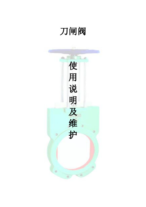
刀闸阀使用说明及维护一、范围本说明主要介绍了手动(手轮、手动拉链)、蜗轮蜗杆传动(正齿轮传动、伞齿轮传动)、气动、电动、液动等刀型闸阀的使用和维护;二、适用工况刀型闸阀适用于矿山电厂的选煤、排渣、城市污水处理、食品、造纸、医药、石油、化工等油品、水、蒸汽管路上,接通或截断管路中的水泥浆、金矿粉、矿砂、炉渣、煤泥、纸浆、木浆、尾矿、纤维、粉尘、化学品处理污水、沉淀池、沥青、料仓出口、水果、谷物、屠宰厂废水等介质。
三、结构介绍刀闸阀按照口径不同有暗杆和明杆两种形式。
刀型闸阀内部可制成V形、三角形、五角形通道。
V型闸板可作为调节控制使用。
刀型闸阀连接形式有对夹式、法兰支耳式,密封有金属对金属硬密封、金属对聚胺脂、带增强的聚四氟乙烯软密封。
图1 刀闸阀典型结构图四、性能规范:五、结构特点:1. 可提升的闸板密封面,可刮除密封面上的粘着物,自动清除杂物。
2. 耐磨合金钢闸板可防止腐蚀引起的密封泄漏,精磨抛光处理可获得最佳密封效果。
刀板底端加工成刀刃状,对松软物料如纤维、纸浆、木浆具有切断功能,同时有良好开启和关闭作用。
在刀板上端安装有硬聚四氟乙烯刮泥器,可防止粉尘、砂砾等擦伤性物质进入填料盒,可显著提高刀板寿命。
3. 严苛工况可选用不锈钢阀体坚久耐用,阀体加强筋设计提高阀体强度,大口径阀门采用双头阀杆螺纹使用启闭更为迅速。
4.阀体、填料涵可采用精密铸造,其中阀体采用凸缘式整体铸造,材质可根据用户需要选用304、316、316L、WCB、2Crl3,密封圈采用橡胶材质,耐腐蚀、耐磨损、不沾渣。
5. 全圆形的直流通道设计不存渣、不卡阻。
6.阀体可采用板焊拼接,焊接采用全焊透式拼接焊,坚固耐用,可节省成本。
7.密封填料采用金属加石墨的成型填料且压紧螺栓可调节压紧力,使阀杆密封安全有效,经久耐用。
7. 短结构长度,可节省原料,安装空间,也有效支持管道强度。
8.支柱式支架结构节省原材料,保证需要的力学性能。
9. 刀型闸阀阀体上的导向块使闸板正确运动。
奥比诺克斯 EX 型刀片闸阀 技术手册说明书

• Pulp and Paper • Wastewater treatment plants • Food and Beverage • Mining • Power plants• Chemical plants• Bulk handling• Etc.Working pressure:Reserves the right to change specifications without noticeDN 50 to DN 250DN 300 to DN 400 DN 450DN 500 to DN 600 DN 700 to DN 1200All valves are tested prior to shipping in accordance with the standard developed by the Quality Control Department at ORBINOX.Other flange connections available on requestSizes: DN 50 to DN 1200 (larger diameters on request) Standard flange connection:DIN PN 10 and ANSI B16.5 (class 150)DIN PN 6 BS “D” and “E” DIN PN 25DIN PN 16 ANSI 125Directives:STANDARD PARTS LISTFor EU Directives and other Certificates please see the document: Directives & Certificates Compliance - Knife Gate Valves – Catalogues and Datasheets10 bar 6 bar 5 bar 4 bar 2 barOBX 05/21The EX model knife gate is an uni-directional wafer valve designed for general industrial service applications. The design of the body and seat assures non-clogging shut off on suspended solids in industries such as:Unique design that mechanically locks the seal in the internal of the valve body with a stainless steel retainer ring. Standard EPDM also available in different materials such as Viton, PTFE, etc.PACKING:Long-life packing with several layers of braided fibre plus an EPDM o-ring, with an easy access packing gland ensuring a tight seal. Long-life braided packing is available in a wide range of materials. The standard stainlesssteel stem offers a long corrosion resistant life. For rising stem handwheel actuators only, a stem protector is provided for additional protection against dust while the valve is in the open position. STEM: ACTUATORS:YOKE or ACTUATOR SUPPORT:EPOXY COATING:The epoxy coating on all ORBINOX cast iron and carbon steel valve bodies and components isapplied by means of an electrostatic process, making the valves corrosion-resistant with a high quality finished surface.The ORBINOX standard colour is RAL-5015 blue. ORBINOX automated valves are provided with gate guards in accordance with EU SafetyStandards. The design feature prevents any objects from being caught accidentally while the gate is moving.Made of EPOXY coated steel (stainless steel available on request). Compact design makes it extremely robust even under the most severe conditions. All actuators supplied by ORBINOX are interchangeable, and supplied with a standard mounting kit for installation purposes on site. GATE SAFETY PROTECTION:DESIGN FEATURESBODY:Wafer style cast monoblock with raised faces and reinforcing ribs in large diameters for extra body strength. Internal cast-in gate wedges and guides allow for a tighter shut-off between gate and seat. Full port design for greater flow capacity and minimal pressure drop. The internal body design avoids any accumulation of solids that would prevent the valve from closing. GATE:Stainless steel gate. Gate is polished on both sides to avoid jamming and seat damage. Bottom of the gate edge is machined to a bevel to cut through solids for a tighter seal in the closed position. The thickness and/or material of the gate can be changed on request for higher pressure requirements. SEAT: (resilient)Flush ports (Fig.2):Allow for cleaning of solids trapped within the body cavities that can obstruct the flow or prevent the valve from closing. Depending on the process, purging can be made with air, steam, liquids, etc.Other materials of construction:Ductile iron, carbon steel, stainless steels (AISI 317, ...), special alloys(254SMO, Hastelloys, …), etc.ORBINOX designs, produces and delivers special fabricated valves for special process conditions (big sizes and/or high pressures).EXT (full lug design):Modified version of the EX model with full lug design for end of lineapplications. Standard flange connection from DIN PN 10, ANSI 150, to AS "D". Sizes available up to DN 600. Fig.1OTHER OPTIONS Bonnet (Fig.1):Assures tight sealing to atmosphere.Reduces packing maintenance.V-port:60 degree and pentagonal port design. Selection depends on the desired fluid control type.Fig.2SURFACE TREATMENTSValve components can be protected or coated for a longer life expectancy, depending on the application of the valves and the valve service conditions. At ORBINOX we can offer alternative treatments and coatings for the different valve components to improve their properties against abrasion (Stellite, Polyurethane…), against corrosion (Halar, Rilsan, Galvanised…) and against adherence (Polishing, PTFE…).We recommend to contact our technical department.Fabricated valves:Wide range of valve extensions availablePlease contact our Technical DepartmentStandard Handwheel (Rising Stem)Handwheel (Non Rising Stem)ElectricLeverACTUATOR TYPESMANUAL:Handwheel (rising stem) Handwheel (non-rising stem) Chainwheel LeverBevel GearOther (square nut)AUTOMATIC:Electric (rising & non-rising stem) Pneumatic (single & double-acting) HydraulicAll actuators supplied by ORBINOX are interchangeableACCESSORIES: Mechanical StopsActuator manual override PositionersProximity Switches Stem ExtensionsLocking device Solenoid valves Limit Switches Floor standsPneumatic Cylinder>250 120 120200 250 250SEAT TYPESMETAL/METALFor applications with: • High temperature• High density media application • In those cases when full tightness is not requiredRESILIENT TYPE "A" • Standard resilient seat.• Temperature limitations according to the selected seat material. Review the above chart or contact our Technical Department for more information.• Seat with replaceable retainer ringTYPE "B" SEAT (metal/metal) For applications with: • High temperature• High density media application • In those cases when full tightness is not required • Replaceable design without disassembling the valveNOTE: all types include an elastomere O-ring (same material as seal), excluding TH, GR and FC.pH2502-13 260 0-14 600 0-14 1200--TYPE "B" SEAT (resilient)• Temperature limitations according to the selected seat material. Review the above chart or contact our Technical Department for more information.• Replaceable and reinforced seat ring available in different materials such as: stainless steel, CA1 5, Ni Hard,…DEFLECTION CONE "C"• Deflects the media away from any valve internal exposed parts (gate, seat, .)• Material: AISI 316, CA15, Ni -Hard, etc. • Face -to-face dimension increases: DN 50 to DN 250 X = 9mm DN 300 to DN 600 X = 12mm Larger diameters on requestMore details and other materials under request Metal/MetalEPDM (E)NBR (N)FKM-FPM (V)VMQ (S)PTFE (T) High temp./Low tightness Acids and non mineral oilsResistance to petroleum productsChemical service/High temp.Food service/High temp.Corrosion resistance TEMPERATURE CHARTSEAT / SEALSPACKINGMaterialMax.T (ºC) MaterialApplicationsMax.T (ºC)PTFE impregn. synth. fibre (ST)Braided PTFE (TH)Graphited (GR)Ceramic fibre (FC)VALVE EXTENSIONSThe extension on a valve allows the operator to open or close the valve from a distance. Different types of extensions can be used depending on the application and the distance from the gate to the actuator.1- Floor stand• A pipe of the required length is added to the valve stem.• Stem and yoke assembly remain in the original position.• A floor stand is normally used at the top of the extension for actuator installationpurposes.• Required dimensions:H1: distance from centre line of the pipe to the base of the floor.d1: (wall bracket) distance from the wall to the face of the connecting flange.Notes:Fig.1Fig. AFig.2a- Any type of actuator can be mounted on the floor stand such as Handwheel, Gear,Electric, etc.b- A wall bracket (Fig. A) is recommended at every 1.5m. This prevents any deviation orbuckling of the extension rod.c- Standard construction of the floor stand is fabricated carbon steel. Other materials areavailable on request. (Fig. 1)d- A position indicator (optional) can be installed for easy visibility of the percentage ofopening of the valve.e- Availability of supports for actuator floor stands (Fig. 2) upon request.2- Tube• Stem and yoke assembly remains in its original position.• Handwheel is replaced by a tube, which rotates at the time of operating the valve.• Stem rises and lowers within the tube.• Ideal for surface box operation, valve can be operated with a T-bar and a square nut.• Required dimensions:H1: distance from centre line of the pipe to the base of the floor.d1: (wall bracket) distance from the wall to the face of the connecting flange.a- Handwheel or square nut operated only.b- A wall bracket (Fig. A) is recommended at every 1.5m. This prevents any deviation or buckling of the extension rod.c- Standard construction of the extension is carbon steel epoxy coated. Other materials are available on request.3- Universal joint 4 - Extended support plates• Universal joints are used in those cases where the alignment of the extension between valve and actuator is not feasible.• Please contact our technical department for more information. • Ideal where long extensions are not required.• Guide bearing is installed at the mid point to prevent any deflection of the rod.Notes:HANDWHEEL (rising stem)• Standard manual actuator• Consists of:- Handwheel: Epoxy coated Cast Iron - Stem- Stem nut- Stem protector• Available from DN 50 to DN 1000• Options:- Locking Device- ExtensionsDN A B C D E F ØG H50 40 119 100 105 129 47 225 420 7 65 40 134 100 115 146 47 225 450 8 80 50 149 100 124 162 47 225 475 9 100 50 169 100 140 187 47 225 520 11 125 50 180 100 150 211 47 225 600 15 150 60 210 100 175 237 47 225 652 18 200 60 262 119 205 309 67 310 822 30 250 70 318 122 250 364 67 310 1022 44 300 70 372 122 300 414 67 310 1122 58 350 96 431 197 338 486 66 410 1323 96 400 100 486 197 392 536 66 410 1427 124 450 106 540 201 432 588 66 550 1594 168 500 110 602 201 485 648 66 550 1707 192 600 110 708 201 590 748 66 550 2022 245 700 110 834 380 686 890 74 800 2778 405 750 110 884 380 760 945 74 800 2900 455 800 110 1015 320 791 989 74 800 2980 512 900 110 1040 320 895 1118 74 800 3215 680 1000 110 1146 320 975 1220 74 800 3400 865Weight (kg.)• Recommended for installation where space is limited.• Consists of:- Handwheel- DN 50-300: Aluminium- DN ≥ 350: GJS400 (GGG40)- Stem- Yoke bushing- Stem nut fixed to the gate• Available from DN 50 to DN 1000• Options:- Locking Device- Extension- Square Nut DriveDN A B C D E F ØG H 50 40 119 125 105 144 63 225 312 65 40 134 125 115 161 63 225 339 80 50 149 125 124 177 63 225 364 100 50 169 125 140 202 63 225 405 125 50 180 125 150 226 63 225 439 150 60 210 125 175 252 63 225 490 200 60 262 142 205 317 73 310 595 250 70 318 142 250 372 73 310 695 300 70 372 142 300 422 73 310 795 350 96 431 197 338 509 98 410 945 400 100 486 197 392 559 98 410 1049 450 106 540 201 432 611 98 550 1141 500 110 602 201 485 671 98 550 1254 600 110 708 201 590 771 98 550 1459 700 110 834 380 686 900 151 800 1737 750 110 884 380 760 945 151 800 1856 800 110 1015 320 791 997 151 800 1939 900 110 1040 320 895 1128 151 800 2174 1000 110 1150 320 975 1255 151 800 2381CHAINWHEEL• Recommended for elevated installations.- Chainwheel: Epoxy coated Cast Iron- Stem- Stem nut- Stem protector• Available from DN 50 to DN 600• Options:- Locking Device- Extension- Rising Stem and Non-rising StemDN A B C D E F ØG H 50 40 119 100 105 129 253 225 420 65 40 134 100 115 146 280 225 450 80 50 149 100 124 162 305 225 475 100 50 169 100 140 187 347 225 520 125 50 180 100 150 211 380 225 600 150 60 210 100 175 237 431 225 652 200 60 262 119 205 309 538 300 822 250 70 318 122 250 364 638 300 1022 300 70 372 122 300 414 738 300 1122 350 96 431 197 338 486 856 454 1323 400 100 486 197 392 536 960 454 1427 450 106 540 201 432 588 1052 454 1594 500 110 602 201 485 648 1165 454 1707 600 110 708 201 590 748 1370 454 2022LEVER Array• Recommended for quick opening and closing.• Consists of:- Lever- Stem- Yoke sleeve- Lever lock• Available from DN 50 to DN 300DN A B C D E F G H I 50 40 119 100 105 129 256 150 408 315 65 40 134 100 115 146 259 150 435 315 80 50 149 100 124 162 307 150 509 315 100 50 169 100 140 187 439 150 637 415 125 50 180 100 150 211 529 150 755 415 150 60 210 100 175 237 620 150 895 415 200 60 262 119 205 309 822 235 1038 620 250 70 318 122 250 364 995 235 1307 620 300 70 372 122 300 414 1166 235 1578 620GEAR• Recommended for valves larger than DN 350 and working pressures greater than 3.5 bar• Consists of: - Stem- Stem protector- Bevel Gear Actuator with Handwheel• Available from DN 200 to DN1200• Options:- Locking device - Extension - Chainwheel- Rising stem and non-rising stem• Standard reduction ratio of 4:1DN A B C D E F ØG H I 200 60 262 119 205 309 584 300 994 200 250 70 318 122 250 364 684 300 1094 200 300 70 372 122 300 414 784 300 1194 200 350 96 431 197 338 472 857 450 1657 262 400 100 486 197 392 522 961 450 1761 262 450 106 540 201 432 574 1053 450 1853 262 500 110 602 201 485 634 1166 450 1966 262 600 110 708 201 590 734 1371 450 2171 262 700 110 834 380 686 890 1623 450 2423 262 750 110 884 380 760 945 1755 450 2555 262 800 110 1015 320 791 993 1886 650 2926 260 900 110 1040 320 895 1123 2120 650 3160 288 1000 110 1146 320 975 1220 2302 650 3342 288 1200 15013904501037152226958503935365• The standard pneumatic actuator (double acting on-off cylinder) consists of: - Ø≤300: Aluminum barrels - Ø≥350: Composite barrels - Aluminum end covers- Stainless steel (AISI 304) piston rod - Nitrile coated steel piston • Available from DN 50 to DN 1000• Supply Pressure: min. 3.5 bar - max. 10 bar. Actuator designed with 6 bar air supply.• For valves installed in a horizontal position, we recommend Uand/or actuator support.• Options: - Hard anodized barrel and covers - Stainless steel barrel and covers - Over/Undersized cylinder - Manual override- Fail safe system (Page EX-14) - Limit switches • Instrumentation (on request): - Positioners- Solenoid valves - Flow regulators- Air preparation unitsDN A B C D E F G H50 40 119 100 105 129 178 115 412 9 C100/62 1/4" G 65 40 134 100 115 146 193 115 454 10 C100/77 1/4" G 80 50 149 100 124 162 211 115 497 11 C100/95 1/4" G 100 50 169 100 140 187 231 115 558 14 C100/115 1/4" G 125 50 180 100 150 211 271 140 632 20 C125/143 1/4" G 150 60 210 100 175 237 296 140 708 25 C125/168 1/4" G 200 60 262 119 205 309 358 175 872 44 C160/220 1/4" G 250 70 318 122 250 364 428 220 1042 67 C200/270 3/8" G 300 70 372 122 300 414 478 220 1192 82 C200/320 3/8" G 350 96 431 197 338 500 549 277 1387 135 C250/375 3/8" G 400 100 486 197 392 550 599 277 1541 165 C250/425 3/8" G 450 106 540 270 432 598 680 382 1710 220 C300/475 1/2" G 500 110 602 270 485 658 730 382 1873 280 C300/525 1/2" G 600 110 708 270 590 758 830 382 2178 330 C300/625 1/2" G 700 110 834 380 686 875 985 444 2546 520 C350/730 3/4” G 750 110 884 380 760 930 1035 444 2725 585 C350/780 3/4” G 800 110 1015 320 791 974 1085 444 2850 650 C350/830 3/4” G 900 1101040 320 895 1105 1202 515 3202 850 C400/930 3/4” G 1000 11011463209751217129651534881060C400/10303/4” GPNEUMATIC CYLINDERWeight (kg.)Standard Cyl.Connect.• This actuator (single acting cylinder) consists of: - Aluminum barrel and covers - Steel spring- Stainless Steel (AISI 304) piston rod - Nitrile coated steel piston• Available from DN 50 to DN 300• Supply pressure: min. 5 bar - max. 10 bar• Options:- Fail open - Fail closeDOUBLE ACTING WITH AIR TANK• Fail safe systems consists of: double acting pneumatic cylinder, air tank and all the neccessary elements according to the available options (solenoid valve, spool valve,…)• Different solution available (pressure switches,...)• Available for all diameters• Supply Pressure: min. 3.5 bar - max.10 barFAIL SAFE SYSTEMSINGLE ACTING (SPRING RETURN)Fail close in power failure shown in figureFail close shown in figureELECTRIC ACTUATOR• Consists of:- Electric actuator - Rising stem- Motor support yoke flange acc. to ISO 5210 / DIN 3338• The standard electric motor is equiped with: - Manual emergency operation - Limit switches (open/closed) - Torque switches• Available from DN 50 to DN 1200• Wide range of types and marks available to meet customer's needs.• Option:- Non rising stemDN A B C D E F ØG H I J L M50 40 119 100 105 129 377 160 547 265 249 62 238 20 x 4 10 65 40 134 100 115 146 404 160 574 265 249 62 238 20 x 4 10 80 50 149 100 124 162 429 160 599 265 249 62 238 20 x 4 10 100 50 169 100 140 187 470 160 640 265 249 62 238 20 x 4 10 125 50 180 100 150 211 504 160674265249 62 238 20 x 4 15 150 60 210 100 175 237 555 160 1055 265 249 62 238 20 x 4 20 200 60 262 122 205 309 669 160 1169 265 249 62 238 25 x 5 30 250 70 318 122 250 364 769 160 1269 265 249 62 238 25 x 5 45 300 70 372 122 300 414 869 160 1369 265 249 62 238 25 x 5 40 350 96 431 197 338 472940200 1440 283254 65 248 35 x 6 70 400 100 486 197 392 552 1044 200 1544 283 254 65 248 35 x 6 90 450 106 540 270 432 610 1172 200 1672 283 254 65 248 35 x 6 110 500 110 602 270 485 670 1280 200 1780 283 254 65 248 35 x 6 95 600 110 708 270 590 800 1565 315 2065 389 336 91 286 35 x 6 140 700 110 834 380 686 900 1763 315 2846 389 336 91 285 40 x 7 120 750 110884380760 945 1882 315 2965 389 336 91 286 40 x 7 140 800 110 1015 320 791980 1948 315 3031 389336 91 286 50 x 8 180 900110 1040 320895 1087 2157 400 3240 389 339 91 286 50 x 8 220 1000 110 1146 320 975 1200 2350 400 3431 389339 91 286 50 x 8 300 1200 150 1390 450 1037 1485 2732 500 4137 430 36511730360 x 9480Stem Ø xpich Torque (Nm)4 - 0 - 0(*) From DN 24”, acc. To MSS SP 44 (class 150)4 - 0 - 0BLIND TAPPED HOLES TAPPED THROUGH THROUGH HOLED。
人民电器 HR3系列熔断器式刀开关 产品说明书
HR3
系列熔断器式刀开关
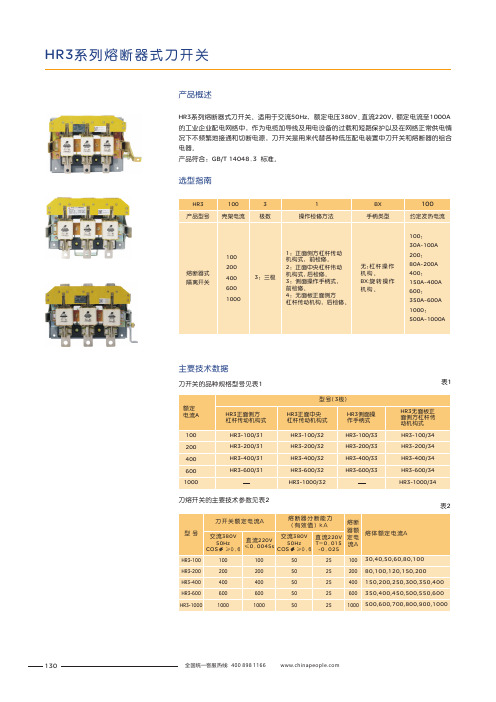
HR3系列熔断器式刀开关。
适用于交流50Hz ,额定电压380V 、直流220V ,额定电流至1000A 的工业企业配电网络中,作为电缆加导线及用电设备的过载和短路保护以及在网络正常供电情况下不频繁地接通和切断电源,刀开关是用来代替各种低压配电装置中刀开关和熔断器的组合电器。
产品符合:GB/T 14048.3 标准。
表1
产品概述
选型指南
主要技术数据
刀开关的品种规格型号见表1
刀熔开关的主要技术参数见表2
表2
130
外形及安装尺寸
刀开关的外形及安装尺寸见图1~图4、表3~表6。
表3注:F*尺寸为开关接通后连杆处最大位置的尺寸。
时
表4注:*尺寸为开关接通后连杆处最大位置的尺寸。
F
时
手柄开孔图
图2
图1
131
表5
注:*尺寸为开关接通后连杆处最大位置的尺寸。
F
时表6
注:*尺寸为开关接通后连杆处最大位置时的尺寸。
F
手柄开孔图
手柄开孔图
订货单位须注明开关的型号规格、电压等级、电流等级、极数、操作方式及数量等,特殊订货请联系我公司有关技术部门。
例如:HR3-400/31 380V 20台。
订货须知
132
HR3系列熔断器式刀开关。
C67双向刀型闸阀说明书

C67 Bi-Directional Knife Gate Valveperimeter seat that provides bi-directional, bubble-tight shutoff.The seat is retained in the valve body by its trapezoidal shape.A relief area has been cast into the valve body behind the seat.Designed to overcome problems common to other perimeterseated designs, the relief area greatly reduces compression setof the seat, allowing it to maintain a tight shutoff performanceover varying service conditions. This unique valve design isavailable in cast stainless steel and carbon steel bodyconstruction and can be supplied with a wide variety of seatmaterials to address a range of application parameters.The C67 has been upgraded with the universal yoke designwhich provides greater range of valve application. The yoke platesinclude a lockout provision for both manual and actuated valves,while greatly simplifying the conversion of valve operators in thefield. The yoke plates also allow for easier mounting of mechanicaland proximity sensors.SpecificationsSize Range2” – 36”Pressure Rating2”-36” 150 psi (10.3 bar) CWP (cold working pressure)Consult factory for higher pressure designs.Temperature RatingAflas Seat 0°F (-18°C) to 400°F (204°C)Viton Seat -30°F(-34°C) to 350°F (177°C)EPDM Seat -50°F (-45°C) to 280°F (138°C)HNBR Seat -20°F (-29°C) to 280°F (138°C)Neoprene Seat -30°F (-34°C) to 180°F (82°C)Flange DrillingANSI 125/150 DrillingConsult factory for other flange drillings.TestingEvery Fabri-Valve Figure C67 valve is fully tested prior to shipment.Testing includes a body shell test, a seat test and a cycling test toinsure proper functioning of moving parts. Please consult thefactory for any special testing requirements.• Standard Shell Test: Hydro test at 1.5 times the rated CWP (coldworking pressure) – Zero allowable leakage• Standard Resilient Seat Test: Hydro test at 15 psi (1 bar) and therated CWP (cold working pressure) – Zero allowable leakage*U.S. Patent #5, 154,3972C67C67 3Trapezoidal Seat TechnologyThe C67 trapezoidal seat design provides bubble tight shutoff across the full pressure rating of the valve. When the gate is opened, the seat remains flush with the valve body, reducing turbulence and media build-up. As the gate is closed, the resilient seat is pushed into the body relief area, reducing compression set of the rubber and maintaining a long-term, tight seal. The trapezoidal shape also eliminates issues from seat rollover and prevents seat pullout due to fluid velocity.Valve ClosedSeat FlushGateReliefSeat Pushed Into ReliefFigure C67Pressure-Temperature Rating -psiTemp 150 66 150 150 150 150 150 150 200 93 142 142 150 150 135 150 250 121 135 135 142 142 128 150 300 149 129 129 134 134 121 150 350 177 123 123 128 128 116 150 400 204 118 118 123 123 112 150 450 232 114 114 118 118 108 150 500 260 111 111 114 114 105 150°F °CCast 304Cast 304L Cast 316Cast 316L Cast 317L Cast WCBA-216Figure C67 Knife Gate Valves C v Ratings, Port Diameter and AreaStandard PortWith V-SeatValve Size C vPort I. D. Port AreaC v Port I.D. Port Area I n. DN Inches Sq. In.Inches Sq. In.2 50 288 2.00 3.1 165 2.00 2.83 75 648 3.00 7.1 355 3.00 6.34 100 1,152 4.00 12.6 515 4.00 9.56 150 2,592 6.00 28.3 1,350 6.00 24.9 8 200 4,608 8.00 50.3 2,050 8.00 38.1 10 250 7,208 10.00 78.5 3,200 10.00 59.0 12 300 10,400 12.00 113.1 4,450 12.00 82.3 14 350 12,650 13.25 137.9 5,350 13.25 98.8 16 400 16,750 15.25 182.6 6,950 15.25 128.4 18 450 21,450 17.25 233.7 10,700 17.25 198.2 20 500 26,700 19.25 291.0 13,250 19.25 245.4 24 600 38,900 23.25 424.6 15,400 23.25 284.7 30 750 61,600 29.25 671.9Consult Factory36 900 89,460 35.25 975.94C67Dimensions: C67 with Handwheel or Cylinder* Figures C67R and C67S with Handwheel Reference Dimensions in (parentheses)C67 with Handwheel or CylinderC67 5Dimensions: C67 with Bevel Gear6” - 14” Valves have a bevel gear ratio of 3:1 Reference Dimensions in (parentheses) 16” - 36” Valves have a bevel gear ratio of 4:1Materials of ConstructionPTFE/Graphite/Viton packing is standardwith Viton and Aflas seals6C67C67 with Bevel GearC67 7B.C67.en-US.2023-07© 2023 Engineered Valves, LLC Fabri-ValveITT Engineered Valves 33 Centerville RoadLancaster, PA 17603, USA Tel: +1 (717) 509-2200Cam-Line, Cam-Tite, Dia-Flo, EnviZion, Pure-Flo, SkotchITT Engineered Valves 1110 Bankhead Avenue Amory, MS 38821, USA Tel: +1 (662) 256-7185ITT Bornemann GmbH 31683 Obernkirchen GermanyTel: +49 5724 390-0EnviZion, Pure-FloVisit our website at Available OptionsBody• Epoxy Coating• Flush Ports: Chest Only, 6” (DN 150) and larger • V-Port• Chest Liners• Thru Drilled Flanges • Alternate Flange DrillingGate• Hard Gate Material • Nickel-TFE Coated Gate • Locking Devices • Gate CoversPacking• Optional Packing Materials • Live Loaded PackingOperators• E-Z Spin Handwheel • Bevel Gear • Chainwheels• Cylinder Actuators • Electric Actuators • Ratchet HandleOther / Accessories• Self-Supporting Yokes • Extended Stems • Rod Boots • Limit SwitchesOptional chest liners fill the clearances between the gate and the chest of the Figure C67 body. Chest liners prevent solids entrapment in the chest area, and also provide increased gate support for high flow/high pressure applications. Standard materials are ultra high molecular weight polyethylene (UHMW) and reinforced PTFE.Chest LinersBoth manual and actuated C67 valves can be equipped with a locking pin to physically lock the gate for safety provisions. This lockout option will function to lock the gate in either the open or closed position. The standard locking pin is constructed of 17-4 stainless steel.Gate Lockout。
欧比诺克斯 EK 系列刀型闸阀 说明书
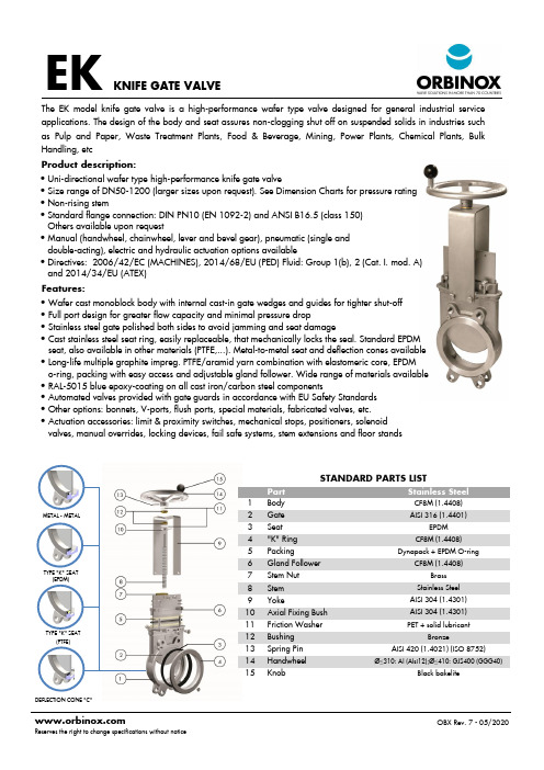
OBX Rev. 7 - 05/2020Reserves the right to change specifications without notice EKKNIFE GATE VALVEFeatures:STANDARD PARTS LIST Part Stainless Steel1 Body CF8M (1.4408)2 Gate AISI 316 (1.4401)3 Seat EPDM4 "K" Ring CF8M (1.4408)5 PackingDynapack + EPDM O-ring6 Gland Follower CF8M (1.4408)7 Stem Nut Brass 8 Stem Stainless Steel 9 YokeAISI 304 (1.4301) 10 Axial Fixing Bush AISI 304 (1.4301) 11 Friction Washer PET + solid lubricant12 Bushing Bronze13 Spring Pin AISI 420 (1.4021) (ISO 8752)14 Handwheel Ø≤310: Al (Alsi12);Ø≤410: GJS400 (GGG40)15 KnobBlack bakeliteTYPE "K" SEAT(PTFE)TYPE "K" SEAT(EPDM)DEFLECTION CONE "C"Product description:• Wafer cast monoblock body with internal cast -in gate wedges and guides for tighter shut-off • Full port design for greater flow capacity and minimal pressure drop• Stainless steel gate polished both sides to avoid jamming and seat damage• Cast stainless steel seat ring, easily replaceable, that mechanically locks the seal. Standard EPDM seat, also available in other materials (PTFE,...). Metal-to-metal seat and deflection cones available • Long -life multiple graphite impreg. PTFE/aramid yarn combination with elastomeric core, EPDM o-ring, packing with easy access and adjustable gland follower. Wide range of materials available • RAL -5015 blue epoxy-coating on all cast iron/carbon steel components• Automated valves provided with gate guards in accordance with EU Safety Standards • Other options: bonnets, V -ports, flush ports, special materials, fabricated valves, etc. • Actuation accessories: limit & proximity switches, mechanical stops, positioners, solenoid valves, manual overrides, locking devices, fail safe systems, stem extensions and floor standsThe EK model knife gate valve is a high-performance wafer type valve designed for general industrial serviceapplications. The design of the body and seat assures non-clogging shut off on suspended solids in industries such as Pulp and Paper, Waste Treatment Plants, Food & Beverage, Mining, Power Plants, Chemical Plants, Bulk Handling, etc• Uni -directional wafer type high-performance knife gate valve• Size range of DN50-1200 (larger sizes upon request). See Dimension Charts for pressure rating • Non -rising stem• Standard flange connection: DIN PN10 (EN 1092-2) and ANSI B16.5 (class 150) Others available upon request• Manual (handwheel, chainwheel, lever and bevel gear), pneumatic (single and double-acting), electric and hydraulic actuation options available• Directives: 2006/42/EC (MACHINES), 2014/68/EU (PED) Fluid: Group 1(b), 2 (Cat. I. mod. A) and 2014/34/EU (ATEX) METAL - METALOBX Rev. 7 - 05/2020Reserves the right to change specifications without notice EKDNABCDEFGH50 16 bar 41 119 125 105 129 178 115 412 9 C100/62 1/4" G 65 16 bar 41 134 125 115 146 193 115 454 10 C100/77 1/4" G 80 16 bar 51 149 125 124 162 211 115 497 11 C100/95 1/4" G 100 16 bar 51 169 125 140 187 231 115 558 14 C100/115 1/4" G 125 16 bar 56 180 125 150 211 271 140 632 20 C125/143 1/4" G 150 10 bar 60 206 125 175 237 296 140 708 27 C125/168 1/4" G 200 10 bar 60 262 142 205 309 358 175 872 46 C160/220 1/4" G 250 10 bar 69 318 142 250 364 428 220 1042 69 C200/270 3/8" G 300 6 bar 78 372 142 300 414 478 220 1192 86 C200/320 3/8" G 350 6 bar 78 431 197 338 500 541 220 1379 135 C200/375 3/8" G 400 6 bar 89 486 197 392 577 599 277 1568 165 C250/425 3/8" G 450 5 bar ⁽¹⁾ 89 540 270 432 643 641 277 1715 220 C250/475 3/8" G 500 4 bar ⁽¹⁾ 114 602 270 485 706 691 277 1882 280 C250/525 3/8" G 600 4 bar ⁽¹⁾ 114 708 270 590 805 791 277 2196 330 C250/625 3/8" G 700 2 bar 118 834 380 686 875 985 277 2571 520 C250/730 3/8" G 750 2 bar 118 884 380 760 930 1035 382 2740 585 C300/780 1/2" G 800 2 bar 118 1015 320 791 974 1085 382 2844 650 C300/830 1/2" G 900 2 bar 118 1040 320 895 1105 1202 382 3220 850 C300/930 1/2" G 1000 2 bar 11811463209751217129638234961060 C300/1030 1/2" GDNABCDEFØGH50 16 bar 41 119 125 105 144 63 225 373 7 65 16 bar 41 134 125 115 161 63 225 400 8 80 16 bar 51 149 125 124 177 63 225 425 9 100 16 bar 51 169 125 140 202 63 225 466 11 125 16 bar 56 180 125 150 226 63 225 500 15 150 10 bar 60 206 125 175 252 63 225 551 20 200 10 bar 60 262 142 205 317 73 310 656 32 250 10 bar 69 318 142 250 372 73 310 756 46 300 6 bar 78 372 142 300 422 73 310 856 62 350 6 bar 78 431 197 338 516 98 410 1013 96 400 6 bar 89 486 197 392 572 98 410 1123 124 450 5 bar ⁽¹⁾ 89 540 201 432 635 98 550 1226 168 500 4 bar ⁽¹⁾ 114 602 201 485 698 98 550 1342 192 600 4 bar ⁽¹⁾ 114 708 201 590 797 98 550 1546 245 700 2 bar 118 834 380 686 890 150 800 1723 405 750 2 bar 118 884 380 760 945 150 800 1855 455 800 2 bar 118 1015 320 795 989 150 800 1934 512 900 2 bar 118 1040 320 900 1118 150 800 2168 630 10002 bar 118115032098012201508002350732DIMENSIONS (mm) Handwheel Non Rising StemKNIFE GATE VALVEDNABCDEFØG HIJLM50 16 bar 41 119 125 105 129 377 160 552 265 249 72 238 20 x 3 10 65 16 bar 41 134 125 115 146 404 160 579 265 249 72 238 20 x 3 10 80 16 bar 51 149 125 124 162 429 160 604 265 249 72 238 20 x 3 10 100 16 bar 51 169 125 140 187 470 160 645 265 249 72 238 20 x 3 10 125 16 bar 56 180 125 150 211 504 160 679 265 249 72 238 20 x 3 15 150 10 bar 60 206 125 175 237 560 160 730 265 249 72 238 20 x 3 20 200 10 bar 60 262 142 205 309 669 160 814 265 249 82 238 25 x 4 30 250 10 bar 69 318 142 250 364 799 160 944 265 249 82 238 25 x 4 45 300 6 bar 78 372 142 300 414 904 160 1044 265 249 82 238 25 x 4 40 350 6 bar 78 431 197 338 472 940 200 1115 283 254 128 248 35 x 6 70 400 6 bar 89 486 197 392 552 1044 200 1219 283 254 128 248 35 x 6 90 450 5 bar ⁽¹⁾ 89 540 270 432 610 1172 200 1347 283 254 130 248 35 x 6 110 500 4 bar ⁽¹⁾ 114 602 270 485 670 1280 200 1455 283 254 130 248 35 x 6 95 600 4 bar ⁽¹⁾ 114 708 270 590 800 1565 315 1750 389 336 130 286 35 x 6 140 700 2 bar 118 834 380 686 900 1763 315 1948 389 336 202 285 40 x 7 120 750 2 bar 118 884 380 760 945 1882 315 2067 389 336 202 286 40 x 7 140 800 2 bar 118 1015 320 791 980 1948 315 2133 389 336 202 286 50 x 8 180 900 2 bar 118 1040 320 895 1087 2157 400 2342 389 339 202 286 50 x 8 220 1000 2 bar 118 1150 320 975 1200 2350 400 2535 389 339 202 286 50 x 8 300 12002 bar 1501400450103714852732500291743036528430360 x 9 480DIMENSIONS (mm) Pneumatic Actuator (D/A)DIMENSIONS (mm) Electric Actuator Non Rising StemWeight (kg.)Standard Cyl.Connect.StemØ x pichTorque (Nm)Pressures⁽¹⁾ 6 bar with duplex gatePressures PressuresWeight (kg.)Actuator designed with 6 bar air supply and for standard catalogue differential pressure。
刀闸阀技术说明

刀闸阀技术说明(Z73X-10Q/10C)一、产品技术参数1. 型号:Z73X-10Q/10C2. 公称压力:1.0Mpa3. 壳体试验压力:1.5Mpa4. 密封试验压力:1.1MPa5. 适用温度:≤80℃6. 适用介质:污泥、污水、清水、饮用水7. 连接形式:对夹式连接二、产品执行标准1. JB/T8691-1998《对夹式刀形闸阀》2. GB/T12221-2005《金属阀门结构长度》3. GB/T17241.6-2008《整体铸铁法兰》4. GB/T13927-2008《工业阀门压力试验》三、产品技术性能特点1.对夹式平底弹性座封平板闸阀获得实用新型专利证书,专利号为ZL201020671122.0。
2. 刀闸阀主要用于固体颗粒、浆液体(纸浆、污水、煤浆、灰、渣水混和物)介质管路上作启闭用途器,接通或截断介质,不允许作节流和调节用,阀门最终工作状态只有全开或全关。
3. 刀闸阀为明杆式或暗杆刀闸阀,阀杆带动闸板一起升降,阀杆上的传动螺纹在阀体外部,可根据阀杆的运动方向和位置直观地判断闸板的启闭和位置。
4. 采用对夹式结构,可节省安装空间,也有效支持管道强度。
5. 阀板采用不锈钢精加工成形,可保证阀门平稳操作,延长密封件的使用寿命。
6. 刀闸阀密封采用丁腈橡胶密封圈以整体嵌入形式固定在阀体上,具有一定的嵌入自由度,能在一定范围内自身调节密封,以保证在压力变化较大的情况下,阀门都能严密关闭。
橡胶密封圈能简易地拆装更换,以实现阀门使用的长效性。
7. 阀杆采用不锈钢制成,强度高、刚性好,耐磨耐腐蚀性强,使用寿命长。
8. 手动刀闸阀采用手轮启闭,手轮上刻有开/关方向,顺时针旋转为关闭刀闸阀。
9. 产品采用标准化设计,所有设备不论是作为一个整体或是它的有关部件都具有绝对的互换性。
10.四、产品零部件材料五、产品外形连接尺寸与结构简图(手动刀闸阀Z73X-10)。
刀闸阀说明书

QB型系列刀闸阀使用说明书浙江中南阀门有限公司目次1.范围2.结构特点与操作原理2.1开启过程2.2关闭过程3.主要技术参数4.安装与使用保养4.1安装4.2调试使用时注意事项4.3贮存、维护及保养1.范围QB型Z73系列刀闸阀系实用新型阀门,具有轻松转动手轮通过阀杆启动闸板切断管线物流,是一种高技术新型闸阀,本阀门执行机构可以配置手动、气动、电动、液动、伞齿轮、杠杆式。
刀闸阀的使用已从普通领域发展到了更为广阔的使用范围。
从矿山排渣发展到城市污水处理;从一般工业管道发展到食品卫生管道系统。
超薄型设计的刀闸阀,彻底解决了普通闸阀、平板闸阀、球阀、截止阀、调节阀、蝶阀等存在的流阻大、安装笨重、占地面积广的疑难问题。
刀闸阀出现后,大量的通用切断和调节类阀门已被金属密封刀闸阀所取代。
本公司生产的QB型刀闸阀,吸取了国内外先进技术和结构优点,排除了其他厂家所产刀闸阀在使用中存在的各种问题,成功研制出真正的金属密封和无磨擦区域的产品,使产品的使用寿命大大提高。
刀闸阀适用于化工、石油轻工、医药、造纸、环保污水、煤矿等输送管道内介质切断或流通。
2.结构特点与操作原理刀闸阀的结构型式如图1所示(以伞齿轮为例),在符合本标准技术要求的条件下,允许设计成其他结构型式,如图2。
1、阀体2、闸板 3-4、标准件 5、填料 6、压盖 7-9、标准件10、阀杆 11、支架板 12轴承 13、手轮 14-15、标准件16、铜螺母 17-18、标准件 19、锲块 20、阀座图1图2QB型系列刀闸阀是一种具有轻型、结构简单小巧、密封性能可靠、使用寿命长、具有切断介质等等优点,刀闸阀的密封结构包括阀体、闸板、密封圈,阀座、锲块。
是通过闸板跟安装在阀座上的密封圈贴面挤压起到密封作用。
2.1开启过程在关闭位置时,闸板受阀杆的机械施压作用,紧插压在阀座与密封圈之间,当逆时针转动手轮时,阀杆带动闸板向上运动,闸板移离密封圈,阀杆继续提升闸板,(同时也使密封圈恢复弹性疲劳状态,从而提高了密封圈的使用寿命),使闸板离开密封面至通径顶部位置时,即刀闸阀开到全通位置。
手动刀型闸阀说明书PZ73H 1030
手动刀型闸阀PZ73W-16P使用说明书PZ73W手动刀型闸阀使用说明书一、产品概述:刀型闸阀是最常用的截断阀之一,本系列阀门适用于安装在煤灰、污水、纸浆粉尘等介质管道上,作为控制介质流动的启闭装置。
全圆形的直流通道设计不存渣、不卡阻。
刀板底端加工成刃状,对松软物料如纤维、纸浆、木浆具有切断功能,同时有良好开启和关闭作用。
可提升的闸板可刮除密封面粘着物,自动清除杂物。
二、性能特点:1)短结构长度可节省原料、安装空间,也有效支持管道强度;2)阀体上导向块使闸板正确运动,挤压块保证闸板有效密封;3)三角形的支架节省原材料,保证需要的力学性能;4)内部可制成V型、三角形,以适应流体调节控制的要求。
三、主要技术参数:七、引用标准设计与制造标准:JB/T8691-1998结构长度:GB/T15188.2-94连接法兰:GB/T9113.1-2000试验与检验标准:GB/T1927六、结构简图:阀门的主要连接尺寸请参照总装配图。
八、维护、保养、安装和使用注意事项1)阀门应整齐地存放在干燥通风的室内。
2)阀门长期存放时应定期检查,对外露的加工表面须更换防锈油,并清除表面的污垢和铁锈。
3)阀门安装前应仔细核对本阀门的性能是否与使用要求相符。
4)用户在安装阀门时,必须弥留阀门驱动的必须空间。
5)安装时应采用扳手将连接法兰的螺母对称交错地拧紧,并应避免螺母扭曲或过紧。
6)本阀使用过程中应经常保持清洁,阀杆螺纹部分及轴承应定期润滑。
7)发现故障时应立即停止使用,查明原因并消除之。
九、可能发生的故障及消除方法。
刀闸阀技术说明(第二版)

刀闸阀技术说明我公司提供的刀闸阀是暗杆的结构形式,我公司提供刀闸阀安装用的所有配套附件。
我公司提供刀闸阀安装用的所有连接螺栓、螺母及垫圈,所提供的紧固件采用ASTM321不锈钢。
我公司提供的刀闸阀规格、数量、连接长度尺寸等满足清单要求。
1、结构与形式我公司提供的刀闸阀适合介质为城市污水处理厂的脱水污泥,环境温度为0~40℃。
刀闸阀安装于污泥输送泵出口侧。
刀闸阀采用双法兰连接,阀体、阀盖采用GGG50球墨铸铁须经防腐处理,阀辨采用GGG50球墨铸铁材料和强化尼龙布衬底硫化包覆NBR橡胶制造,采用全流面积式设计,不易堆积杂质。
阀体有足够的强度,安装后不变形,能灵活开闭。
阀板的设计符合流体力学性质,具有较小的水流阻力,并在启闭时有效的降低噪音和气蚀。
刀闸阀的密封面采用ASTM316不锈钢材料制造,阀门的密封性能好,耐磨耐腐蚀,使用寿命长。
刀闸阀在进口端介质压力作用下,阀瓣自动开启到位,在电动执行机构动作下能迅速关闭,以防止介质大量倒流。
刀闸阀二侧的法兰尺寸按GB12380-90标准,公称压力P=1MPa。
阀门两端法兰螺栓孔的不同心度没大于螺栓与螺栓孔间隙的1/2,螺栓孔中心圆直径的允许偏差和相邻两孔间的弦距离的允许偏差为螺栓与螺栓孔间隙的1/4,任何连续几个孔之间的弦距离的总误差为:DN≤500mm时不超过±1.5mm;600mm≤DN≤1200mm时不超过±2.0mm;DN≥1400mm时不超过±2.5mm。
阀门的所有铸铁件内腔进行防腐处理,除锈等级达到Sa1/2等级要求,最后在所有流道的过流内腔进行重防腐处理,以提高其耐腐蚀性能。
所有涂覆材料干后不溶解于水,不影响水质,且不因空气、温度变化而发生异状。
2、引用与执行标准GB13932-92 《通用阀门铁制旋启式止回阀》GB/T12221-2005 《金属阀门结构长度》GB/T13927-2008 《工业阀门压力试验》GB50231-2009 《机械设备安装工程施工及验收通用规范》GB50334-2002 《城市污水处理厂工程质量验收规范》GB/T 17241.7-1998 《铸铁管法兰技术条件》GB/T 17241.6-2008 《整体铸铁法兰》GB/T 17241.3-1998 《带颈螺纹铸铁管法兰》GB/T 17241.2-1998 《铸铁管法兰盖》GB/T12237-2007 《石油、石化及相关工业用的钢制球阀》3、主要材料阀体、阀盖 GGG50球磨铸铁阀瓣 GGG50球墨铸铁+强化尼龙层+橡胶覆层销轴 ASTM420不锈钢密封面 ASTM316不锈钢紧固件 ASTM304不锈钢4、阀门试验我公司提供所有主要阀门元件包括阀座,阀辨,轴和密封件等材料的测试报告。
RAYDO SKGV 11系列 全衬聚氨酯刀闸阀 使用手册说明书
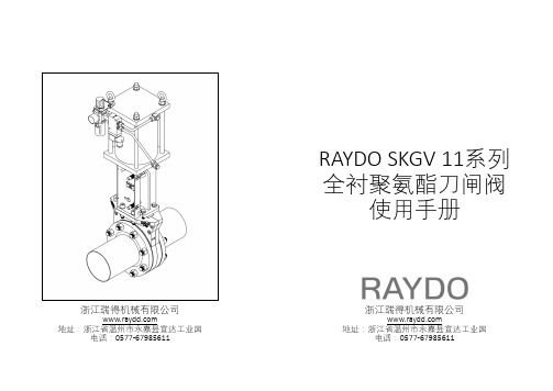
RAYDO SKGV 11系列全衬聚氨酯刀闸阀使用手册浙江瑞得机械有限公司地址:浙江省温州市永嘉县宣达工业园电话:*************浙江瑞得机械有限公司地址:浙江省温州市永嘉县宣达工业园电话:*************安装阀门到管线上时特别注意事项:安装阀门时应使阀门处于关闭位置;安装前,将阀门、配管法兰、法兰密封预装好; 将阀门垂直吊起至安装位置; 法兰与管道使用点焊连接; 将阀门移走,完成焊接;冷却后再将阀门与配管法兰连接好;切勿将阀门装于配管法兰与管道直接焊接,法兰过热将导致聚氨酯损毁。
•一、安装指南1.1 安装前检查阀门铭牌,不要将阀门安装在超出阀门铭牌温度和额定压力的场所。
1.2 尽可能将阀门垂直地面安装,横装、斜装不利于阀门排渣和启闭。
1.3 阀门按照正确的流体方向安装,参见阀体侧向承压方向箭头。
做止回功能的阀门,应按介质回流方向安装。
1.4 与阀门连接的管线必须正确对中并有适当地支撑。
管线法兰的不对中可能导致阀体或法兰连接处的泄漏。
1.5 配管法兰应该是平面型的,以和聚氨酯阀衬上的密封环完全贴合。
推荐首选带颈对焊或承插焊平面型法兰。
在阀门的两侧都要求有法兰。
请勿使用平焊法兰。
软性法兰面伸缩节不得直接连接阀体,否则会造成内衬受挤压变形并咬死阀板,导致阀门无法动作。
• 1.6 在阀腔部位的螺纹孔要求特别注意并确保螺栓的正确长度。
超过允许的最大穿透深度将戳破阀体和阀衬导致阀门不能动作。
1.8 法兰螺栓按照交叉的顺序错开至少三个孔依次拧紧。
如果开车后法兰漏泄,用稍微大的力再拧紧法兰螺栓。
1.9 如果使用衬胶法兰或者凸面法兰,过大的法兰力矩可能导致阀门不能动作。
1.10 如果在阀板密封处出现漏泄,均匀地拧紧压盖密封螺栓, 力量应该刚刚能阻止泄漏为好。
过紧将可能导致阀门不能正常工作。
1.11 当阀门以水平与地面方向安装时,要确保执行机构有合适的支撑,保证执行器和阀门的对中性。
没有支撑可能由于没有正确对中而导致执行器或阀门故障。
- 1、下载文档前请自行甄别文档内容的完整性,平台不提供额外的编辑、内容补充、找答案等附加服务。
- 2、"仅部分预览"的文档,不可在线预览部分如存在完整性等问题,可反馈申请退款(可完整预览的文档不适用该条件!)。
- 3、如文档侵犯您的权益,请联系客服反馈,我们会尽快为您处理(人工客服工作时间:9:00-18:30)。
1、 打开阀门检查阀门密封面是否有颗粒或杂质。
阀体密封 2、 检查密封圈是否完好,若密封圈出现划痕或者有不完整
面泄漏
的现象应尽快更换密封圈。
3、 检查密封是否划伤,若有返回厂家更换。
阀门与管道 1、 检查密封面胶垫,看其是否有破损的情况,如若破损尽
的接触面漏 快更换密封面胶垫。
水 2、 均匀拧紧管法兰两头螺栓
3
http://www.wxbcit.com 0510-87890991 402798973@qq.com
要求是否相同。 5.1.2 阀门在管道安装时要对应介质流向合理安装阀门,操作部位要安放在 便于阀门起闭操作与布线的位置。 5.1.3安装使用前必须对阀门进行综合性能检查,阀门的密封圈和传动部位, 气动、电动装置的行程控制机构及开度(位置)指示机构等,都必须逐项地 进行检查。 5.1.3.1 阀门内腔和密封面不允许有污物附着。 5.1.3.2 检查各连接螺栓是否均匀拧紧。 5.1.3.3 阀门应清洗干净并在各转动部位加注润滑油(脂) 5.1.3.4 阀门的气动、电动装置的综合性能检查必须在阀门启闭无卡阻的情 况下进行。 5.2 调试使用时注意事项 5.2.1电动阀门的电缆接地芯线必须安全可靠地接入内接地螺钉。 5.2.2 检查填料是否均匀压紧并密封,但又不得过紧防碍闸板升降。 5.2.3 在使用过程中如发现电机过热或运转不正常、控制机构失灵 5.2.4 液压油(46 号)半年更换一次。 5.2.5 在正常开启关闭的情况下,盘根一年更换一次。
电液刀闸阀
使 用 说 明 书
无锡市博柯英腾机电设备有限公司
http://www.wxbcit.com 0510-87890991 402798973@qq.com
1.产品描述 LWPZ系列电液刀闸阀系实用新型阀门,是一种高技术新型闸阀,本阀门执
行机构可以配置气动、电动、液动。刀闸阀的使用已从普通领域发展到了更 为广阔的使用范围;在污水处理行业中应用广泛。
1、限位器 2、电液推杆 3、加油孔 4、维修孔 5、放油孔 6、电机 7、电机与油泵连接法兰 8、支架连接处 9、集成块 图1
1
http://www.wxbcit.com 0510-87890991 402798973@qq.com
2 1、电液推杆 2、阀门支架 3、限位器 4、阀门闸板 5、阀体 6、出水 口连接处 7、固相取样法兰
本公司生产LW系列电液刀闸阀,吸取了国内外先进技术和结构优点,排 除了其他厂家所产刀闸阀在使用中存在的各种问题,成功研制出真正的密封 和无磨擦区域的产品,使产品的使用寿命大大提高。LWPZ系列电液刀闸阀适 用于造纸、环保污水污泥切换武装等条件下。 2.结构特点与操作原理
刀闸阀的结构型式如图1所示(以电液为例),在符合本标准技术要求的 条件下,允许设计成其他结构型式,如图2 图3。
l 6、阀门安装的最佳位置为水平,立装的角度不得超过垂直面 15 度,如
若超过垂直面 15 度必须做支撑架或吊杆,才能确保阀门工作正常。
l 7、阀门需定期保养,不得随意碰撞和挤压,以免影响密封性能。
4. 主要技术参数
项目名称 公称通径DN 公称压力PN 试验压力式
主要性能规范 单位
图3
2
http://www.wxbcit.com 0510-87890991 402798973@qq.com
LW系列电液刀闸阀是一种具有结构简单小巧、密封性能可靠、使用寿命
长、具有切断介质等等优点,刀闸阀的密封结构包括阀体、闸板、密封圈,
阀座、锲块。是通过闸板跟安装在阀座上的密封圈贴面挤压起到密封作用。
3、安装和使用注意事项
l 1、严格按照介质流向指示安装和验收阀门。
l 2、安装前必须检查阀门腔内和密封面及管道内腔,不得有焊接飞溅点
和其他杂物。
l 3、各连接部位螺栓要求均匀拧紧。
l 4、检查阀门上密封填料部位,要求压盖压紧,既保证阀板上密封又保
证阀板启阀灵活。
l 5、用户在安装阀门时,需预留阀门执行机构的相应空间。
限位开关 不起作用
闸板跟压 块结合处
泄露
1、检查限位开关是否完好,如本身有故障请及时更换。 2、检查开、关限位是否接反,如接反调整过来即可。 1、当阀门在出库、入库、运输过程中浸油或浸脂的油脂会有
少量的外泻或氧化,此时需对称的拧紧压盖螺栓即可。 2、当阀门在库内存放时间超过一年没有定期加注润滑油时,
数值
mm( in ) 50(2″)--1000(40″)
Mpa(CLASS) 1.0、1.6、150Lb、2.5Mpa
Mpa(CLASS) ℃
密封
1.1PN
壳体强
1.5PN
度
-29℃-+300℃
纸浆、泥浆、污水、砂
浆、
气动、电动 、液动
5.使用保养 安装前应仔细阅读使用说明书,认真核对型号、规格以及其他标志与现场使用
5
4
http://www.wxbcit.com 0510-87890991 402798973@qq.com
电机工作 阀门不开
启
1、 检查油位。看油箱中是否有油,如若没有请加满。 2、 调节集成块的安全卸载压力,顺时针拧螺栓调节至阀门
开启为止。 3、 检查清洗油泵后看其是否有压力,若没有请更换油泵。
