TS12联机教程
图解宽带路由器共享上网设置过程

图解宽带路由器共享上网设置过程【IT168 专稿】宽带路由器作为一种主要专门针对宽带共享上网设计的产品,因其具备共享上网简单方便、安全性高,灵活可靠等优点,开始越来越受到需要进行共享上网的家庭、SOHO等用户的青睐。
今天我们就为大家详细介绍如何使用宽带路由器进行共享上网。
为那些需要购买和已经购买宽带路由器产品的网友朋友们提供帮助。
使用宽带路由器共享上网时,我们要经过对宽带路由器和需要共享上网的PC机进行设置,这里笔者使用中怡数宽的宽带路由器的软件来逐步进行讲解,假设用户已经对所有的硬件进行了正确的连接,只为大家讲解如何设置宽带路由器来实现共享上网的内容,一般宽带路由的设置界面及功能都大同小异,所以这些设置同样适用于其他的宽带路由器产品。
1、宽带路由器的设置。
在硬件连接完成以后,我们需要有一台已经与宽带路由器的LAN口相连接的PC来进行具体的设置。
在设置之前,我们应该确认这台机器已经装有TCP/IP网络协议,笔者使用的机器是XP操作系统,其他操作系统平台的设置基本上都差不多,下面来看看我们需要在这台PC上进行如何的配置。
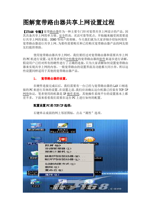
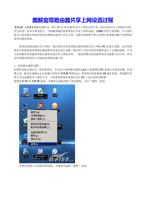
配置设置PC的TCP/IP选项:右键单击桌面的网上邻居图标,点击“属性”选项。
在弹出的窗口中选择本地连接,右键单击选择“属性”选项。
点击看大图这时,在弹出的对话框中双击“Internet协议(TCP/IP)选项”。
在弹出的对话框中选择“使用下面的IP地址”选项,这时我们便可以设置这台PC的IP地址了。
宽带路由器的出厂IP地址一般都为192.168.0.1,所以我们在配置的时候需要将配置的PC设置和宽带路由器在同一个网段当中。
这里,我们将这台PC的IP地址设置为192.168.0.254,子网掩码255.255.255.0,默认网关为192.168.0.1。
点击看大图通过以上的设置,我们就可以登陆的路由器进行具体的配置工作了,首先双击桌面的IE浏览器,在地址栏内输入192.168.0.1的IP地址。
IT-12D Ver_2.0 IT-12M 用户手册说明书

INTERPRETATIONIT-12D Ver_2.0IT-12M SYSTEMUser’s ManualImportant NoticeAll the safety and instructions for operation and use of the equipment should be read carefully• before the system is operated.Please keep this user manual for future reference.• Please follow all the operation instructions.• Cleaning: Make sure to turn off the power supply before cleaning. Use a dry soft cloth to clean • the equipment.Don’t leave the product in a place with high humidity and temperature.• Do not use any accessory, which is not recommended by the manufacturer .• Do not place the equipment on an unstable stand; Please use appropriate package or original • package by the manufacturer before transport to avoid damage caused by strong shake during transporting.Adequate ventilation is good for the maintenance of the equipment.• Power supply AC 100-240V.• Grounding: 3-wire grounding plug.• Hot swapping is prohibited.• Total 11 sets of IT-12D can be connected in one system. The cumulative cable • length should not exceed 70 meters. For particular requirement, please contact the nearest JTS Service Centre for information.For service, please contact the nearest JTS Service Centre. Do not take the equipment apart by • unauthorized personnel.All JTS products are guaranteed for 1 year except for the cases as follows caused by personal • reasons:A : Damage or malfunction caused by personal factors such as dropping, striking and so on.B : Damage or malfunction caused by improper handling of the operator.C : Parts loss or damage by taking apart by a unauthorized personal.Only use JTS tailor-made cables to connect the system.• Turn off the power supply and unplug the equipment from the power supply in case the • equipment is not in use for a long time.Upon receipt of the product, please fill out the Warranty Card enclosed and post it to JTS • Service Centre nearby in your region.TO REDUCE THE RISK OF ELECTRIC SHOCK,DO NOT EXPOSE THIS EQUIPMENT TO RAIN OR MOISTURE.WARNING:To prevent fire or shock hazard,do not expose units to rain or moistureCAUTION: To reduce the risk of electric shock, DO NOT open covers, no useable serviceable parts inside. Refer servicing to qualified service personnel onlyThis label may appear on the bottom of the unit due to space limitations.The lightning flash with an arrowhead symbol,with an equilateral triangle, is intended to alert the user to the presence of uninsulated dangerous voltage within the products enclosure that may be of sufficient magnitude to constitute a risk of electric shock to persons.The exclamation mark within an equilateral triangle is intended to alert the user to thepresence of imporyant operating and maintenance (servicing)instructions in the literature accompanying the appliance.Attention: Installation should be performed by qualified service personnel only in accordance with the National Electrical or applicable local codes.Power Disconnect: Units with or without ON - OFF switches have power supplied to the unit whenever the power cord is inserted into the power source; however,the unit is operational only when the ON - OFF switch is in the ON position. The power cord is the main power disconnect for all units.1. System Introduction2. Product Introduction2-1 Language Distributor // IT-12M2-2 Interpreter Console // IT-12D2-3 Accessories3. System Installation & Connection3-1 General Description3-2 System Connection // Connection Cables3-3 Connection of Audio Cables3-4 System Mounting Instructions4. System Setup & Operation5. Technical Data 1 2 2 4 7 8 8 9 10 12 13 15INDEXRemark:JTS Company reserves the right to modify any issue without notice in advance.If any detailed information needed, please contact the local agent or JTS distributor in your region. JTS is the registered trademark of JTS Professional Co., Ltd.1The JTS IT-12 interpretation system consists of IT-12M and IT-12D.• The IT-12M works as main unit to provide power, input and output interface, and control.• The IT-12D is an interpreter console allowing two interpreters work together. Interpreters can• choose either floor channel for original language for direct interpretation or relay interpretation available via the relay select key.For small venue crossing interpretation is available here.• The whole system supports 11 interpreter consoles for simultaneous interpretation and delivers • 12 languages to audiences.The product is a stand along system. It is compatible with any conference system. So no matter • a new installation or an existing project needing expansion with interpretation IT-12 can easily meet the requirement.Together with JTS wireless system and any infrared system more audiences can participate in a • conference.INTERPRETATION SYSTEM22-1 Language Distributor // IT-12MCOMBO socket microphone input: This COMBO socket provides +48V Phantom power to a microphone with balanced XLR or unbalanced φ6.3 connector. The input signal will be mixed with the Original (CH0).Gain: Adjust input sensitivity of the COMBO socket. The adjustable range is ±10dB.Interpreter channel indicator: Light-On to indicate the correspondent channel is active. Flashing to indicate the correspondent channel is standby.Signal level indicator: the brightness of this LED indicates the signal level of the cor-respondent channel. Power on indicator (Red).Power Switch: Push the”│” on this switch will be turn system on, and push the”○” on this switch will turn system off.Power supply socket (3-wire grounding plus) with built in fuse, T2A/250V.DC power output: The IT-12M includ 12 outputs of DC power supply (+15V/500mA) to wireless transmitters, like JTS TG-10STX tabletop wireless transmitter.Interpreter console interface (D-sub 25pin socket):11 interpreter consoles can be connected in daisy chain (IT-12D).Record IN connector (RCA): external signal from play back devices will be mixed with the Original (CH0) for recording.Record output connector (RCA): Connect to recording equipment. The original signal (CH0) mixed with REC. IN will be recorded.12345678910113Original (CH0, floor channel) output (RCAx2/symmetrical output) : Original (CH0) balanced output with RCA connecters.12CH audio output interface: #0 to 11 correspond to the Original (CH 0) and 11 sets of Interpreter Consoles. Signals are for distribution to audiences via JTS wireless systems. Notice: any channel not in use will be assigned with CH0 as input.Original (CH0) volume control: This potentiometer adjusts the Original (CH0) sensitivity. Adjustable range is ±10dB.Original (CH0) input socket: This φ6.3mm balanced connecter is connected to an output of a conference system or PA as the original signal of the interpretation system.Alarm sound input:φ6.3mm jack / unbalanced input.Slow output: When a Slow Key on the IT-12D is activated this Slow output will generate an 1 sec. pulse to request the lecturer to slow down.Alarm control input: A short cut of Alarm Ctrl. and GND will activate alarm procedure. All channels will receive alarm signal, and indicator LED will change from Light-On to Flashing.121314151617182-2 Interpreter Console // IT-12DENTER key: To set the active channel of interpreter console. When switch on Switchthe ENTER indicator starts flashing. After push one of the selectable channels (fromCH1 to CH11 with Light On) this active channel can be stored to this interpreterconsole by pushing the ENTER key. Then switch off the Switch to end the procedure.CH1~CH11 Channel Output Key:• MODE switch at LOCK position: Under setting state, press it to select a selectable chan-nel (indicator on) for interpretation output. Only 1 channel can be set in one InterpreterConsole. The indicator of the activate channel is in green.• MODE switch at OPEN position: All of channel indicator are off when power oninitially. All channels are open to interpreter as long as it is not occupied by others. Whenthe channel is activated the Channel Output Key is in green. The indicator flashes in redwhich means this channel is in use by others.Note: MIC. ON/OFF at OFF state, the activate channel will be releasedwhen this channel number on other interpreter console is selected.19282820INTERPRETATION SYSTEM45Relay interpretation monitor (MONITOR): After pressing RELAY key, an interpreter can turn the monitor rotary knob to select an interpreted language he/she can understand to interpret.Headphone volume control (VOLUME A, VOLUME B): To adjust the volume of the headphones.Relay interpretation switch (RELAY): In case the interpreter doesn’t understand the original language, they can press the key and switch Monitor to another interpreted language from other interpreter for further interpretation.Floor Channel Switch (ORIGINAL): When the system start, the setting is by default, press it to listen to the original language (the speech from CH0).Mute Key (COUGH CUT): In case the interpreter coughs. Keep pressing the key to mute the line, meanwhile the indicator is on. When released, the line returns to working status.MIC ON/OFF button (MIC.A ON/OFF, MIC.B ON/OFF): Press it to turn the microphone on, the indicator will be on. Press it again to turn off the MIC.Only one microphone can be on at a time. MIC. A and MIC. B will override each other.Reminder key (SLOW): In case the delegate speaks too fast for the interpreter to follow, press it to request the delegate to slow down.MODE setting switch (OPEN / LOCK): The MODE switch needs be decided before power on. At the OPEN mode an interpreter can activate any channel in any time as long as it is not occupied. All channels are set off at the initial state, then an interpreter must select channel key which he wants. At the LOCK mode the interpreter can choose only one output channel which will not be taken by other users (setting procedure refer tostep and “System and Operation” chapter for more detail).Setting switch (SET): When all Interpreter Console are connected, setting of a channel of each console is needed for first time installation at LOCK mode. First turn the Switch to “ON”, the ENTER key will start flashing. According to above Step No.20 to select onechannel for the console. Then turn the Switch to “OFF” to finish the channel setting.To starting the channel setting procedure just turn the setting switches (SET) from “OFF”to “ON”. Finish the channel setting procedure by turn the setting Switch from “ON”to “OFF”.XLR microphone input: Each interpreter unit including 2 balanced XLR microphone input sockets with +48V Phantom power. These balanced microphones will be mixed with MIC. A/B.Input interface (INPUT): to connect the first Interpreter Unit to the IT-12M and the second one to the Output interface of the first unit (25-pin socket).29292929222123242526272829303132 33 34 35Output interface (OUTPUT): for connection with the next Interpreter Unit (25-pin plug).Recorder interface (REC OUT): φ3.5mm stereo, for connection with a recorder to record the interpretation. (Available on both left and right side of the Interpreter Console).Microphone input (MIC IN): φ3.5mm dummy stereo, for connection with microphone(Available on both left and right side of the Interpreter Console). Earphone output (EARPHONE):φ3.5mm stereo, for connection with interpreter headset (Available on both left and right side of the Interpreter Console).INTERPRETATION SYSTEM 62-3 AccessoriesAccessories are standard parts for a complete system installation, general description are as follow:IT-12-C3: 3 meter cable with D-sub 25-pin M/F on each end.Used to connect Interpreter Console (IT-12D) in daisy chain and to IT-12M.•Connecters: 1 Plug, 1 Socket.•3.System Installation & Connection3-1 General DescriptionIT-12 Interpreter System has a compact dimension and is easy for installation. IT-12Dinterpreter consoles are connected in daisy chain and the first IT-12D is connected to themain unit IT-12M.A detailed description of IT-12 Interpreter System installation and connection will begiven by diagrams and examples in this chapter.3-2 System Connection // Connection CablesAll consoles are connected via D-Sub 25-pin cable. A 25-pin 3 meter cable (with a plugand a socket) is included in each IT-12D Interpreter Console to connect the interpreterunit to Main Unit IT-12M or to each other. On the rear panel of IT-12D there are twoD-Sub connecters, the “INPUT” is a plug and the “OUTPUT” a socket. Connect theplug from the 25-pin cable to the Main unit IT-12M then the socket from the 25-pincable to the plug “INPUT” on the first Interpreter Console. And then connect the plugof the second 25-pin cable to the socket “OUTPUT” of the first Interpreter Console and the socket is connected to the plug “INPUT” of the next Interpreter Console. Then all the interpreter units are connected in daisy chain. As many as 11 interpreter units can beconnected for 12 languages (including floor channel) interpretation. Extension cablescan be used between Interpreter Consoles and Main Unit IT-12M (IT-12-C3/C6/C12/ C18).It is strongly recommended to use JTS tailor-made cables to ensure the best performance.CH113-3 Connection of Audio CablesCable connection plays an important role in the long distance audio transmission. Improper connection will result in interference. For example:(1)Connection for Unbalanced to Balanced transmission cable:Practical example: after the audios from signal source of mono RCA output, they go through to the IT-12M balanced input “LINE IN” (φ6.3mm jack) via unbalanced output.GND(SHIELD)shielded netBAL. + OR UNBAL.HI.BAL. - OR UNBAL.LO.353637* Note: This connection is not applicable to Balanced to Unbalanced transmission. Otherwise, the signal source of balanced output may be damaged.(2)Connection for Balanced to Balanced transmission cable:Practical example: After the audios from wired and/or wireless microphones are mixed via the mixer, they go through to the IT-12M balanced input “LINE IN” (φ6.3mm jack) via balanced output.(3)Connection for Unbalanced to Balanced XLR transmission cable:Practical example: the recording output of IT-12M “REC. OUT” (unbalanced output) to PA system or media recording input XLR interface (balanced input).* Note: This connection is not applicable to Balanced to Unbalanced transmission. Otherwise, the signal source of balanced output may be damaged.3-4 System Mounting InstructionsIT-12M Main unit Installation(1)Dimension (LxWxH):421 x 213 x 44mm (2)Colour: Silvery black (3)Weight:2.65Kg(4)“L” shape rack mount bracket for 1U 19-inch standard cabinet.(5)Mounting InstructionsA pair of rack mount brackets are equipped with the IT-12M , unscrew the screwson both sides firstly , then fasten the brackets with these screws and put the IT-12Min the rack, finally install the unit onto the rack with 4 screws .3839404.System Setup & Operation4-1 General DescriptionThis chapter provides a comprehensive and detailed description on how to setup and op-erate IT-12 Interpreter System Main Unit (IT-12M) and Interpreter Console (IT-12D).(1)OPEN Mode: Interpreter Console Output Channel Select (IT-12D)Select the Console with one of the Channel Output key ‘1, 2… 11”; for example: Ifyou want this unit to be NO. 1; just press “1”. Then the indicator on the key will lighton in green while the channel is not occupied. If the indicator on the key flashes in redthat means the channel is occupied by other units. When the MIC. ON/OFF of theactivated channel is at OFF state, the activate channel could be released when otherinterpreter console selects the same channel number.(2)LOCK Mode: Interpreter Console Output Channel Select (IT-12D)Interpreter Console must be assigned with one unique output channel before beingused. The procedure is as:a.Make sure the connection is correct, and then turn on the IT-12M.b.Turn the “SET” setting switch from “OFF” on the rear panel of the InterpreterConsole to “ON”, the indicators of “ENTER” on the unit starts flashing. The indica-tors of available channels will turn RED. Pay attention only one channel can beactivated.c.Assign the Console with one of the Channel Output key “1,2….11”, for example:If you want this unit to be NO 1, just press “1”. Then the indicator on the key willchange to Green light, press “ ENTER ” key to store, the indicator of “ ENTER ”will keep light on;d.Turn the “SET” setting switch to “OFF”, the “ENTER” indicator will turn off, thatmeans the output channel selecting procedure is completed;e.If cross interpretation is needed OPEN mode should be selected.f.Repeat the same procedure (Steps b~d) to assign all the Interpreter Consoles.(3)To Cancel Selected Output Channel (only for LOCK mode)a.Turn the “SET” from “OFF” to “ON”.b.Push the “ENTER” for 3 seconds. Then all Channel Output Indicators will turn off.c.Turn the “SET” from “ON” to “OFF”. The Console will be of factory setting now.(4)The Operation of IT-12D Interpreter Console:The Interpreter Console is designed with digital technologies and used in conjunction with interpreter headset. Each Console allows two interpreters to work on it. The operation procedures are as follows:a.At LOCK mode, when the output channel is selected an interpreter only needpush the MIC ON/OFF key to activate the microphone or deactivate it.b.At OPEN mode, an interpreter can press any Output Channel key to deliver thecorrespondent language. The available channel will show a green indicator. A flash-ing red indicator means the channel is occupied.c.Put on the headset, adjust the microphone to an appropriate position and controlthe volume (Floor language is “ORIGINAL” as defaulted). Press “MIC. A/B ON/ OFF” to start the interpretation.d.In case the interpreter doesn’t understand the floor language. He/she can select alanguage familiar with from other interpreter for relay interpretation. First press“RELAY” key, the indicator will be on, and then switch the MONITOR to choose a familiar language for interpretation.e.In case the Interpreter wants to cough, keep pressing “COUGH CUT” key to cutoff the language output, release it to continue the interpretation.f.When the speaker speaks too fast for the interpreter to follow, the interpreter canpress “SLOW” key to remind the speaker to slow down. A pulse signal will comeout as remind from the IT-12M to the speaker desk.g.Each Interpreter Console accommodates A/B two interpreters to work, the opera-tion A/B interpreter is the same.5. Technical Data5-1 System environmental Conditions5-2 Main Unit IT-12M Technical DataTransport Temp.: -40○C~+70○C Operational Temp.: 0○C~+45○C Max. Relative humidity: <95%Item..................................................Power supply..............................System consumption...........DC power output..................D-SUB power output.........Line In sensitivity....................Alarm In sensitivity................MIC In sensitivity...................Alarm Ctrl....................................Slow output................................CH0~CH11 output level CH0 balance output level REC OUT output level.....REC IN input level................protocol.........................................Dimension (LxWxH).........Color................................................Weight............................................Specification 110-240Vac 90W+15V/0.3A*12DC+15V/2A-30dB±2dB LEVEL VR at MAX.-20dB±2dB-51dB±2dB Gain VR at MAX.Shorted to GND +12V,Pulse 1sec.180mV±20mV85mV-GND85mV±10mV 170mV±15mV -25dB±2dB RS-485421*213*44mm Silvery Black 2.65KgInterpretation Unit (IT-12D) Technical DataItem.................................................. Unit power................................... Unit power consumption. MIC sensitivity......................... XLR MIC sensitivity............ Earphone output level........ REC OUT output level..... Protocol......................................... In/Out interface...................... Dimension (LxWxH)......... Color................................................ Weight............................................SpecificationDC+15V100mA±10mA-45dB±2dB-45dB±2dB120mV±10mV at 33Ω load, volume MAX. 140mV±10mVRS-485D-Sub 25P plug and socket330*206*57mmSilvery-blue black2.5Kg。
用集线器让多台电脑共享上网

2008年08月03日星期日下午04:23一. 必要条件:二台机子,都是WindowsXP操作系统.一条ADSL宽带线路,一个ADSLmodem,一个HUB(集线器,也可以是4口的交换机)路由器可当交换机用,三条网线.二. 硬件设置:Modem的网线连到HUB,HUB再引出二根网线连到二台电脑网卡.三. 软件设置1.主机软件设置(1)把宽带连接共享出来:打开宽带连接的属性页,切换到”高级”标签,把”Internet连接共享”几项都打上勾.(2)设置网卡属性:本地连接一属性一Internte协议(TCP/IP)-属性IP地址:192.168.0.1子网掩码:255.255.255.0默认网关:192.168.0.1(3)DNS服务器地址怎么填写?请打开命令行程序:开始-所有程序-附件-命令提示符,输入:ipconfig/all再回车,抄下DNSServers.我的是202.96.107.29和202.96.107.282.客户机软件设置(1)设置网卡属性:本地连接一属性一Internte协议(TCP/IP)-属性IP地址:192.168.0.2子网掩码:255.255.255.0默认网关:192.168.0.1(2)DNS服务器地址怎么填写?请打开命令行程序:开始-所有程序-附件-命令提示符,输入:ipconfig/all再回车,抄下DNSServers.我的是202.96.107.29和202.96.107.28如此设置后,主机拨号上网,客户机也能上网了.是不是很简单呢双机互联双机互联方法很多,你可以使用两块以太网卡,通过非屏蔽双纹线(UTP)连接;也可以通过串口或并口直接连接,或使用USB接口连接,还可以利用计算机的红外线接口无线连接以及通过两台MODEM通过拨号实现远程共享等等。
在这些方法中,用两块网卡通过双绞线连接是最简单方便同样也是最常用的一种连接方式,下面我们就着重介绍通过这种方式来实现双机互联。
12远程联机服务器 Telnet ssh vnc xdmcp rsh

远程联机服务器Telnet / SSH / VNC / XDMCP / RSH (1)本章的行前准备工作 (1)远程联机服务器 (1)什么是远程联机服务器 (1)服务器类型( Server )的联机程序 (2)工作站类型( Workstation )的联机程序 (3)有哪些可供登入的类型? (3)Telnet 服务器 (4)安装、启动与关闭服务 (4)安装 (4)启动与关闭: (5)好用的联机软件 (7)iptables, TCP_Wrappers, 纯建议 (8)以比较限制的设定档来规范联机的IP : (8)root 不能直接以telnet 连接上主机: (9)加上防火墙iptables (10)加上防火墙/etc/hosts.allow(deny) 机制 (10)建议事项: (11)SSH 服务器 (11)联机加密技术简介: (12)SSH protocol version 1 (12)SSH protocol version 2 (13)启动SSH 服务 (13)ssh 客户端联机: (14)Linux Client: ssh (14)关于Server Keys 的纪录数据:~/.ssh/known_hosts (16)Linux Client: sftp (17)Linux Client: scp (18)Windows Client: putty (19)Windows Client: psftp (24)Windows Client: Fliezilla (24)详细设定sshd 服务器 (25)制作不用密码可立即登入的ssh 用户 (29)1. 在Client 端建立Public 与Private Key (30)2. 在Client 端放置私钥: (30)3. 在Server 端放置可以登入的公钥: (31)安全设定: (32)/etc/ssh/sshd_config (32)/etc/hosts.allow 及/etc/hosts.deny (33)iptables (33)XDMCP 服务器 (34)X Window 的Server/Client 架构 (34)设定XDMCP (36)客户端登入 (37)客户端是Linux 主机: (37)客户端是Windows 主机: (38)关闭XDMCP (43)VNC 服务器 (43)RSH 服务器 (49)RSH Server (51)RSH Server 的启动 (51)设定可以使用RSH 的来源主机与账号:/etc/hosts, /etc/hosts.equiv, ~user/.rhosts (52)让root 也可以使用RSH : (53)RSH Client (54)测试RSH : (54)利用rcp 复制: (54)以rsync 进行同步镜相备份 (55)重点回顾: (57)课后练习 (58)远程联机服务器Telnet / SSH / VNC / XDMCP / RSH一部连上Internet 上面的您的个人主机,最重要的是什么呢?大概就是如何让您自己可以联机进入自己的主机,并且进行所谓的『远程操控』了吧!也就是说,您可以在任何具有连上Internet 的计算机中,以远程联机软件连上Internet ,并藉由您主机上面的远程联机服务器软件提供的功能,直接登入您的主机来进行操控的工作!此时,您将发现Linux 有趣又好玩的地方啰!在早期的Unix Like 机器当中,几乎都提供Telnet 这个远程联机服务器软件,不过,Telnet 本身是以『明码』来传送您操作的数据,安全上面是值得来思考要不要开放吶!这个时候就有需要了解一下传送过程中以加密动作来传送数据封包的SSH 这个远程联机服务器软件啦!另外,除了纯文字接口登入主机来进行操控之外,在现在的Linux distributions 当中,还可以利用X 相关的服务来帮助我们以图形接口登入喔!很棒吧!^_^本章的行前准备工作在这个章节当中我们会使用客户端的联机软件联机到主机端来操作主机,所以你必须要了解到你的主机防火墙必须要开放,并且要取消SELinux 才行!另外,登入时会分析到的PAM 模块也需要进行了解吶!本章后半部会介绍X Window 的远程登入,所以你也必须对于X Server/client 的架构有点了解才行。
莱卡TS12说明书

For M5|Adr 106|KD1 9 BM2 1.29126 m |HD 38.611 m | |
For M5|Adr 107|KD1 BM1 1.1993 m |HD 39.484 m | |
For M5|Adr 5|KD1 1##### 0.342025463 15|Rf 1.53542 m |HD 20.384 m | |
For M5|Adr 6|TO Measurement repeated 15| | | |
For M5|Adr 7|TO Start-Line BFFB 1111| | | |
For M5|Adr 169|KD1 13 1.63078 m |HD 14.319 m | |
For M5|Adr 170|KD1 14 | | |Z 3.26427 m
For M5|Adr 171|KD1 14 0.74677 m |HD 13.856 m | |
For M5|Adr 8|KD1 3HI05 1 1111| | | |Z 2.501 m 2.4963 0.0047
For M5|Adr 9|KD1 3HI05 1 1.45931 m |HD 13.522 m | |
For M5|Adr 12|KD1 2 1.55919 m |HD 13.487 m | |
For M5|Adr 36|KD1 5 0.68845 m |HD 47.059 m | |
For M5|Adr 37|KD1 4 1.41764 m |HD 46.324 m | |
For M5|Adr 38|KD1 5 | | |Z 3.28353 m
局域网中两台无线路由器联接配置方法图文教程

我说话从来不会详细说的,只是简明说的,设房家的为A路由器,你住宿的为B路由器:1、将你两台电脑的本地连接IP地址设为“自动获取IP地址”。
2、将B路由器恢复出厂设置,然后将B路由器的登录IP改为:192.168.99.1(这点你不需要理解),连接类型:动态获取IP地址。
(如果房东设有固定IP,就填静态IP)。
3、将A路由器传来的网线接到B路由器的WAN端口上。
4、将B路由器的LAN端口分别接到你两台电脑上(不分顺序)。
这回基本能上网了,哈哈。
图解迅捷FW300R无线路由器与腾达837R无线路由器桥接 WAN介质(无线WAN)方式第一种。
(路由器当交换机用)简单但会浪费端口,A的LAN 连接 B的LAN 口关闭B的DHCP服务器。
改B的LAN口IP地址和A不再同一网段(可以是同一网段,这么做只是不和A 路由器IP地址冲突)电脑连到B路由器的LAN口就可以上网了。
二(NAT地址转换) A的LAN口连B的WAN口设置B路由器WAN(这里选择静态IP)和A路由器为同一网段(如192.168.1.60)还有网关设置为A路由器的LAN地址,,B路由器LAN口为不同网段(比如192.168.0.1)注意这时候哦连在B路由器上的电脑IP地址要和B路由器LAN在同一网段。
局域网中两台无线路由器联接配置方法图文教程详细出处参考:接触过宽带路由器的用户,大都了解宽带路由器上的端口有WAN口和LAN口之分。
宽带路由器在工作过程中有这样一个特点:从LAN到WAN方向上的数据流默认不受限制通过路由器,从WAN到LAN方向上默认不能通过。
(注:无线宽带路由器的无线接入部分从属于LAN的范围)也就是说,默认情况从局域网内电脑上发出的数据包进入路由器的LAN口,可以顺利通过路由器从WAN口被发出,但是从WAN这一端主动过来的数据包进入WAN口以后,路由器默认是不让那些数据包通过的。
通过耗子的实际测试,其实从有线路由器接出的网线,可以通过联接无线路由器的WAN口和LAN口的方式,都可实现无线网络的使用。
昂达TT-12iD互动白板系统配置指南说明书

With Interactive WhiteboardUSBRGB OUTTo projectorRGB INFromcomputerUSBTo computerPlug-in forAC adaptorRearpanel1Configureyour classroomBasic ConfigurationInstall ImageMate softwareAC plugsAC plugsRGB/HDMI cableHDMI OUTTo projectorTo speakerWith ComputerPower on the TT-12iDZoom and FocusPress the Auto-focus button to focusafter zoomingTwist the zoom knob to zoom in/out2LED lightRotateRotate the camera column close to asmall object,turn the camera headhorizontally to view students giving apresentation, speech, etc.Rotate the arm 180°and position camerahead downward for left-handed users.34Capture and ReviewA. Insert SDcard/USBflash driveC. Review saved imagesUse buttons toscroll and select.QUICK TRAINING GUIDE: TT-12iD1Pause the camera image. Press again to unfreeze.Menu(see page 2)Adjust brightnessView computer desktopView document camera imageB. Capture imageTraining Video (TT-12): /tt-12-interactive-document-cameraHDMI INFromcomputerZoom In/OutPowerIncreasebrightnessView images/videos from SD cardTake a picture and save to SD cardView computer desktopCompare picture: Compare the live image to a saved image from the SD card.Auto-focus:Press after zooming 5Control the TT-12iD from anywhere in the classroom27Connect the TT-12iD to a computer and install Image Mate to save images and videos to thecomputer . You can also annotate on the live image and record time-lapsephotography (set interval time in Settings beforebeginning time-lapse)Take a pictureand save to computerRecord video and time-lapse photographyRemote to control the document camera from the desktop Open previously saved filesView live imageSelect the time-lapse interval, file format, etc.Additional Menu features6Return to live image Capture students’ curiosity by applying the Mosaic feature, letting them predict the displayed object.Use Microscope mode with the Optional Microscope Attachment to display slide images for the entire class to see at once.InstallImage Mate softwarePress the Menu button tocustomize preferences and apply special modes such as Mosaic and Microscope. 1-800-947-ELMO /ElmoClassrooms /ElmoCamsDownload Image Mate at /t-12iD-interactive-document-cameraDecrease brightness The Highlight allows you to emphasize a specific area of the image. Move thehighlight using arrow buttons [▲][►][▼][◄].Record video Start and stop video recordingThe Mask feature lets you to hide the answer to a written problem or following along when reading text, etc. To move the mask, use [▲][►][▼][◄].Press the Scroll to zoom instantly then use[▲][►][▼][◄] to scroll around your image.。
ASUS Home Server TS mini 家用伺服器快速使用手冊说明书

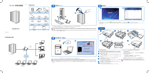
包裝盒內容物TS mini 家用伺服器快速使用手冊家用網路連線示意圖路由器TS mini 家用伺服器多媒體裝置桌上型電腦筆記型電腦HDDInternetH D DI n t e r n e t遠端遙控存取啟動您的 TS mini123安裝軟體至第一部電腦上11. 將 ASUS Home Server TS mini 連接器軟體光碟放入與家中網路連線的電腦上的光碟機中,安裝精靈將會自動啟動。
若您未開啟光碟自動安插通知功能,那麼您也可以到本光碟中找尋 Install.exe ,並使用滑鼠左鍵雙擊 Install.exe 開啟安裝精靈畫面。
2. 點選 下一步,並依照畫面上的提示完成安裝,然後進入 Windows Home Server Setup 設定畫面。
在此您將需要輸入伺服器的名稱、administrator password(主管理者密碼)以及數個相關設定。
2121. 將 AC 電源變壓器上的專用插頭連接至 TS mini 家用伺服器後面板上的 DC IN 插孔,並將另一端插頭連接至電源插座上。
2. 將網路線一端連接至伺服器後面板上的網路(LAN)埠,然後將另一端連接至您的寬頻路由器。
本產品不支援無線連接至寬頻路由器,您必須使用網路線連接 TS mini 及寬頻路由器。
然而,在您將伺服器連線至您家中的網路後,家中的電腦就可以經由無線的方式與您的伺服器連線。
3. 按下位於 TS mini 伺服器上方的電源按鈕,開啟電源。
開始使用3121. 使用滑鼠左鍵點選 Windows Home Server 圖示 開啟登入畫面,然後輸入主管理者密碼(administrator password)後按 登入 Windows Home Server 主控台。
2. 在 Windows Home Server 主控台操作介面,您可以開始在家用伺服器上進行遠端存取、檢視、分享、保護重要檔案。
翻到本快速使用手冊的背面,查閱您可以透過 Windows Home Server 主控台進行哪些任務。
PLC联机操作手册

危险
在此手册中没有“警告”的项目。
警告
小心
1. 有关产品和手册的事项
本手册由计算机制造商发表,它对手册中涉及的描述为“限制”和“可用状态”的事项有优先 解释权。
未被列入此手册的项目请理解为“不可能”。
此手册是假定已提供了全部任选功能。在使用此设备前请确认由计算机制造商发布的规范。 根据 NC 系统的型号而定,某些屏幕面和功能可能不同或者可能不能使用。
当用户 PLC 通过此功能被停止时,即按使用旋转开关 NCSYS 的同样方法停止时,紧急停止就会 发生。此时,首先是使用专用的紧急停止键执Байду номын сангаас紧急停止,然后将用户 PLC 调整到紧急停止状 态。
目录
1 概述...................................................................... 1
设置错误值有可能引起计算机的非法操作或者失去控制。在编程时要给予足够的重视。 2. 有关编程的事项
如果在创建、校正、添加或插入梯形图后,未按下 5CONVT 和 INPUT 键,则已被创建的梯形图 会丢失。 在使用此功能时,通过将位于控制器下部的旋转开关 NCSYS 设置到 1 号位置(STOP)(停止), 就可将 PLC 调到停止状态。
–2–
2. 系统配置 2.2 通用配置
2.2 通用配置
在进行联机操作开发时,系统的配置如下所示:
梯形图编辑、梯形图监控以及 PLC 运行/终止,等等。
通过个人计算机可进行新的开发。
设Se定ttin与g a显nd示Dis装pla置y Unit
B基as本e I/OI/OUni装t 置
梯形图利用设定与显示装置开 发(联机操作开发)。
怎样把2台电脑连接在一起

首先你先别用router进行二台电脑连接,你先用原来台式电脑用正确的拔号连接上网。
打开:控制面板→性能和维护→管理工具→事件查看器→系统刚连接网络的时候,系统第一个就是你电信加密的帐号,密码不变。
上面会显示~+英文或数字+地区名+电话号码,用户连接网络信息。
这就是你的正确的帐号,也就是系统自动拔号的正确帐号。
第二步就是设置router,用路由器连接二台电脑利用IE进入,进入网址是192.168.1.1。
一般路由器进入用户名和密码都是admin。
进入设置向导用事件查看器生成的帐号和原来的密码设置拔号用户名。
在里面再设置开机和断线的时候自动拔号。
第三步就是设置IP。
打开网上邻居→查看网络连接→本地连接属性→Internet协议属性→自动获取IP,DNS地址选项选择→确定。
1、宽带路由器的设置。
在硬件连接完成以后,我们需要有一台已经与宽带路由器的LAN口相连接的P C来进行具体的设置。
在设置之前,我们应该确认这台机器已经装有TCP/IP网络协议,笔者使用的机器是XP操作系统,其他操作系统平台的设置基本上都差不多,下面来看看我们需要在这台PC上进行如何的配置。
配置设置PC的TCP/IP选项:右键单击桌面的网上邻居图标,点击“属性”选项。
在弹出的窗口中选择本地连接,右键单击选择“属性”选项。
这时,在弹出的对话框中双击“Internet协议(TCP/IP)选项”。
在弹出的对话框中选择“使用下面的IP地址”选项,这时我们便可以设置这台PC 的IP地址了。
宽带路由器的出厂IP地址一般都为192.168.0.1,所以我们在配置的时候需要将配置的PC设置和宽带路由器在同一个网段当中。
这里,我们将这台PC的IP地址设置为192.168.0.254,子网掩码255.255.255.0,默认网关为19 2.168.0.1。
通过以上的设置,我们就可以登陆的路由器进行具体的配置工作了,首先双击桌面的IE浏览器,在地址栏内输入192.168.0.1的IP地址。
安防监控KV8001全高清网络智能高速室外球机安装说明书

12.3.1 环境设置............................................................................................................................ 18 12.2.2 最低个人电脑配置要求.................................................................................................... 20 12.3 快速连接 IPNetcam.......................................................................................................
一条网通宽带 如何连接两台电脑同时上网

一条网通宽带如何连接两台电脑同时上网一条网通宽带如何连接两台电脑同时上网? 悬赏分:30 - 解决时间:2022 -9-5 19:08刚电话10060 网通允许两台机器公用一条线路上网我现在手头上只有一台能正常上网的笔记本(没有无线模块), 又买了台式机, 山东济南网通安装宽带时的华为adsl客户端设备(只能引出一条连接电脑的网线) 我需要买什么怎么设置才能让两台机器互不干预的情况下能同时上网? 我用的是济南2m的两个机器上网的网速都是2m还是共用2m?提问者: roverbu - 试用期一级最正确答案买台路由器,和两条网线就可以实现.具体设置看路由说明书就行(可根据不同路由设置不同) 一般路由器带有四口交换机,交换机的功能是根据不同需要,调用最大的带宽来工作的.如果两台电脑没有同时进行大量的网络数据传输时,少量网络数据传输可以缩小两台电脑的同时访问网络的机率,这种机率有时可以到达很小,甚至没有.两台电脑访问网络时就存在较多的时间差,交换机就是从这个时间差时把这台机器所空闲带宽留另一台机器使用.所以此时你可以认为每一台电脑都可以用上2M的带宽.如果两台电脑都在进行大量的网络数据传输时,大量的同时网络数据传输可使两台电脑同时访问网络的机率扩大,当两台电脑同时访问网络时,交换机就只能按集线的原理一样把带宽给平均分配.这时两台电脑就是共用2M带宽. 所以我们在一般的网络浏览,根本感觉不到网络的减慢.两台电脑同时上传或下载较大的网络数据时就可以觉察每一台电脑的速度是平时只用一台电脑的速度的一半.答复者: berll - 秀才二级提问者对于答案的评价:谢谢感觉你说的最用心评价已经被关闭目前有 0 个人评价相关内容 ? 如何连接路由器使两台电脑同时上网 ? 一条网线,两台电脑上网? ? 网通客户端“宽带我世界〞能不能一账号使两台机器同 ... ? 鞍山网通宽带出什么事了?? ? 安装网通宽带的问题更多关于网通ADSL如何两台电脑上网的问题>> 查看同主题问题:网通宽带连接一条电脑其他答复共 5 条 Hub答复者:东方步兵 - 门吏三级9-4 02:23 9-4 02:58 我来评论>>买台路由器一百左右买回来按说明书设置好就可以上网了普通的路由器可以供最少三台以上电脑共享一条宽带上网答复者: heyuchang - 试用期一级9-4 02:24可以共享上网,请看下面我们要知道局域网最大的特点就是可以实现资源的最正确利用,如:共享磁盘设备、打印机等,从而可以在组建的局域网内部互相调用文件,并可在任何一台共享打印机上进行打印;当然我们也可以借助Wingate或Sygate等软件多机共享一台Modem上网;或者通过代理效劳器连上Internet,享受非一般的速度。
GMOD联机方法

GMOD联机方法联机方法1:一个人玩无聊?没伴?没趣联机吧~联机方法分为三种:IP联机浩方联机蛤蟆吃联机(本人不喜欢蛤蟆吃联机)联机方法2:好的,让我们首先来说说IP联机吧!如果是要自己创建房间呢,一定要知道自己的IP,啥?你不知道自己的IP!哈哈,不用担心!先让我们打开网页,在搜索上面输入IP,就会跳出来一个IP地址查询,点进去。
上面会写着您的IP地址是:[XXX.XXX.XX.XXX]复制下来就可以了,但光复制还是不能联机!呃,你创建好了房间,你的朋友现在就想进来玩?恩哼!按~就可以打开了!!什么你说打不开!如果遇到打不开的情况,先打开选项,刚跳出来就是键盘选项,点下面的高级设置,会有快速切换武器和启用开发者控制台。
只要在开发者控制台上打一个勾就行了。
按~之后,有些人直接就把IP给复制上去点确定了,结果是进不去的,你们还应该加一个强制命令,就是connect比如说,connect XXX.XXX.XX.XXX这样的,然后点回车就可以进入了。
(有时候IP联机方法是加不进去的)联机方法3:呜啊,浩方联机,最喜欢了!!首先,我们先下个浩方,下好之后注册一个号点进去。
点开之后往左边看,有一竞技频道,点进去有47的竞技游戏,一直往下翻,翻到一个叫CS SOURCE 的游戏,点进去,随便进入一房间然后点击设置,找到游戏目录,然后有些人目录找好了直接进去,发现.......居然是CS游戏别急别急,我们重新来设置,设置好目录之后,发现下面有一个游戏运行参数,输入-steam -console -game garrysmod -steam 进去的就是gmod啦~~~~就点开始游戏哦!如果你要在浩方建房间让别人来玩,直接点创建房间。
如果你要加入别人的房间,点加入游戏的局域网。
然后能看到服务器,然后你又随便点了几个频道,比如互联网什么的,再回来看的时候,局域网没服务器了现在开始教你们刷服务器,首先,我们还在局域网频道,然后点互联网频道之后退出gmod。
实训:直连两台游戏主机

实训:直连两台游戏主机
简介
本文档将介绍如何通过直连方法连接两台游戏主机,以便进行多人游戏。
直连方法
步骤1:准备工作
1. 确保两台游戏主机都已经正确连接到电源和显示器。
2. 确保两台游戏主机都已经安装了相同的游戏,并且网络连接已经正常。
步骤2:连接主机
1. 使用一根网线,将两台游戏主机的局域网接口与对方直接连接。
2. 在两台游戏主机的设置中,确保局域网连接已经启用。
步骤3:配置网络
1. 在主机的设置中,进入网络设置并选择手动配置。
2. 根据网络要求设置IP地址、子网掩码和默认网关。
步骤4:测试连接
1. 在主机的设置中,找到网络测试或连接测试功能。
2. 进行连接测试,确保两台游戏主机已经成功直连。
注意事项
- 直连方法只适用于局域网环境,不能进行跨网直连。
- 确保两台游戏主机的硬件和软件均正常运行。
- 如果无法成功直连,请检查主机的网络设置是否正确配置。
以上是直连两台游戏主机的简要步骤和注意事项。
通过正确地进行直连,你可以和朋友们一起畅快地享受多人游戏的乐趣!。
笔记本共享上网

e:请问:两台迅驰笔记本电脑如何无线连接?作为迅驰技术的一个重要组成部分,Intel PRO/Wireless 2100无线网络模块为笔记本电脑所带来的便捷性是显而易见的,迅驰笔记本电脑可以借助它无拘无束地实现无线连网。
内置无线网卡的笔记本电脑除了可以通过AP(即Access Point,俗称无线网络基站)来连上局域网外,还可以单独与其它具有无线功能的笔记本电脑组成局域网,以便方便地实现数据共享。
由于WinXP对无线网卡的支持较以前版本的操作系统都要完善,因而用无线网卡来组成局域网的笔记本电脑,建议安装WinXP。
两台迅驰笔记本电脑或其它具有相同无线网卡规范(现行的大都为IEEE 802.11b)的笔记本电脑组成局域网的设置如下。
双机互连1.在BIOS或其它管理程序中启用两台笔记本电脑的无线网卡。
2.设置无线连接方式。
在任务栏右侧的无线网络连接状态指示图标上单击鼠标右键,选择“查看可用的无线连接”,在弹出的对话框中点击“高级”,进入“无线网络连接属性”页面,在“无线网络配置”选项中(图1),单击右下角的“高级”按钮,并在出现的页面中更改“要访问的网络”选项,即把“任何可用的网络”更改为“仅计算机到计算机”,按“关闭”结束此步骤。
两台笔记本电脑都须进行此步操作。
3.选择其中一台笔记本电脑,回到图1的“无线网络配置”页面,单击“首选网络”下方的“添加”按钮,弹出“无线网络属性”(图2),在“服务设置标志(SSID)”栏中输入一个标志,本例中输入的标志为“lzy”,依次点击“确定”按钮退出。
4.在另一台笔记本电脑上,再次用鼠标右键单击任务栏右侧的无线网络连接状态指示图标,这时可以发现在弹出的“连接到无线网络”对话框中已经有了一个标志为“lzy”的可用无线网络,选中它并在“允许我连接到选择的无线网络,即使它是不安全的”选项前打上“√”,然后点击“连接”按钮。
这时,如果把鼠标指针指向任务栏上的无线网络连接状态指示图标,可以看到两台笔记本电脑无线连接的有关情况,如速度、信号强度等。
图解宽带路由器共享上网设置过程

图解宽带路由器共享上网设置过程【IT168 专稿】宽带路由器作为一种主要专门针对宽带共享上网设计的产品,因其具备共享上网简单方便、安全性高,灵活可靠等优点,开始越来越受到需要进行共享上网的家庭、SOHO等用户的青睐。
今天我们就为大家详细介绍如何使用宽带路由器进行共享上网。
为那些需要购买和已经购买宽带路由器产品的网友朋友们提供帮助。
使用宽带路由器共享上网时,我们要经过对宽带路由器和需要共享上网的PC机进行设置,这里笔者使用中怡数宽的宽带路由器的软件来逐步进行讲解,假设用户已经对所有的硬件进行了正确的连接,只为大家讲解如何设置宽带路由器来实现共享上网的内容,一般宽带路由的设置界面及功能都大同小异,所以这些设置同样适用于其他的宽带路由器产品。
1、宽带路由器的设置。
在硬件连接完成以后,我们需要有一台已经与宽带路由器的LAN口相连接的PC来进行具体的设置。
在设置之前,我们应该确认这台机器已经装有TCP/IP网络协议,笔者使用的机器是XP操作系统,其他操作系统平台的设置基本上都差不多,下面来看看我们需要在这台PC上进行如何的配置。
配置设置PC的TCP/IP选项:右键单击桌面的网上邻居图标,点击“属性”选项。
在弹出的窗口中选择本地连接,右键单击选择“属性”选项。
这时,在弹出的对话框中双击“Internet协议(TCP/IP)选项”。
在弹出的对话框中选择“使用下面的IP地址”选项,这时我们便可以设置这台PC的IP地址了。
宽带路由器的出厂IP地址一般都为192.168.0.1,所以我们在配置的时候需要将配置的PC设置和宽带路由器在同一个网段当中。
这里,我们将这台PC的IP地址设置为192.168.0.254,子网掩码255.255.255.0,默认网关为192.168.0.1。
通过以上的设置,我们就可以登陆的路由器进行具体的配置工作了,首先双击桌面的IE浏览器,在地址栏内输入192.168.0.1的IP地址。
首先双击桌面的IE浏览器,在地址栏内输入192.168.0.1的IP地址。
tplinkmr12u路由器共享宽带怎么设置

tplink mr12u路由器共享宽带怎么设置
tplink mr12u路由器因其出色的性能、配置简单和超高的性价比,深受广大用户的喜欢;不过对于没有网络基础的用户来说,完成路由器的安装和共享宽带配置上网参数,任然有一定的困难,下面是店铺给大家整理的一些有关tplink mr12u路由器共享宽带的设置方法,希望对大家有帮助!
tplink mr12u路由器共享宽带的设置方法
1、输入管理地址
打开电脑桌面上的IE浏览器,清空地址栏并输入192.168.1.1(管理地址),回车后页面会弹出登录框。
2、登录管理界面
在登录密码框中,输入路由器默认的管理密码:admin,点击登录,进入管理界面。
1、开始设置向导
进入路由器的管理界面后,点击设置向导,点击下一步。
2、选择上网方式
如果您通过运营商分配的宽带账号密码进行PPPoE拨号上网,则按照文章指导继续设置。
如果是其他形式的上网方式,请选择并参考对应设置过程:
上网方式选择 PPPoE(ADSL虚拟拨号),点击下一步。
3、输入宽带账号和密码
在对应设置框填入宽带运营商提供的宽带上网账号和密码,并确定该账号密码输入正确。
4、设置无线参数
修改SSID(即无线网络名称),在PSK密码中设置无线密码,点下一步。
5、设置完成,重启路由
点击完成。
弹出对话框提示重启,点击确定。
重启完成后,电脑连接修改后的无线网络(zhangsan)。
进入路由
器管理界面,点击运行状态,查看 WAN口状态,如下图框内IP地址不为0.0.0.0,则表示设置成功。
至此,网络连接成功,路由器已经设置完成。
- 1、下载文档前请自行甄别文档内容的完整性,平台不提供额外的编辑、内容补充、找答案等附加服务。
- 2、"仅部分预览"的文档,不可在线预览部分如存在完整性等问题,可反馈申请退款(可完整预览的文档不适用该条件!)。
- 3、如文档侵犯您的权益,请联系客服反馈,我们会尽快为您处理(人工客服工作时间:9:00-18:30)。
TS12模拟火车联机教程
一、前提条件:
1、你是一个超级狂热的火车爱好者和模拟火车玩家。
2、下载安装好TS12火车游戏版本。
3、拥有TS12版本正版序列号。
4、拥有Auran账号。
注意:
1、正版序列号的购买
目前国内玩家大部分都是使用的盗版游戏,现在花费58元人民币就可以购买到一个正版序列号。
当然如果想体验联机游戏那么正版序列号是必须的,大家可以量力而行。
具体购买地址在这里给大家贴出来,当然我跟这家网店没有任何关系:/item.htm?id=10137564343&
2、账号的注册
登陆:https:///planetauran/register.php
按照页面提示进行操作!
二、进入游戏
请按照图片步骤操作!
选择Options
输入购买到的正版key,点击Add
输入在官网注册的账号和密码。
链接TRAINZ,更新游戏版本。
之后点击OK!进入游戏!
三、进入游戏
看到屏幕上边框的人头变成绿色的说明你的游戏已经联网!
先进入游戏自带的多人任务:
这个时候可以自己创建一个联机任务,或者加入到别人创建的联机任务之中,这里讲解一下如何加入别人创建的任务。
这里可以看到三明建立的一个任务:
注意联机任务的标志,是一个绿色向下的箭头。
点击加载进入,等服务器连接完成之后就ok了!
正在连接!
之后就进入了游戏,开始联机之旅吧!
四、体验联机
在联机游戏的过程中,可以体验真实的火车世界。
如果玩家数量够多,那么会非常有意思,例如可以这样:
A玩家担当调度员,控制车站信号灯,安排其他玩家列车通过。
B玩家C玩家D玩家担当司机,值乘各类列车,在调度员安排下避让、会车、调车、办理客运、按时刻运行等!
同时在任务中加入图定列车,由联机玩家控制的列车在线路上插空运行,保证不影响图定列车也要准点运行!
等等一系列的内容等待开发!
进入联机任务之后你可以选择自己要担当的角色:
本教程作者
“江南”与“三明一站台”共同研究完成!。
