逆变器特性说明书
2000W正弦波逆变器说明书

★★★设备使用前,请仔细阅读使用说明书正弦波逆变器使用说明书11一、概述我公司生产的纯正弦波逆变器,可将蓄电池的直流电能逆变成额定电压输出的正弦波交流电,供用户负载使用。
本逆变器外观大方、指示直观、操作方便。
具有交流自动稳压输出、过压、欠压、过载、过热、短路、反接等完善的保护功能。
核心控制元件采用美国原装微控制器,功率器件则采用优质的进口器件。
本电源整机效率高,空载损耗底。
经大量实验证明,该系统运行安全、稳定、可靠,使用寿命长。
具有很高的性能价格比。
二、功能简介1、充电控制功能:风力发电机输出的交流电能先转换成直流电能,然后和太阳能电池板一起对蓄电池进行充电。
2、逆变输出功能:在打开前面板的“逆变开关”后,本电源即将蓄电池的直流电转化成额定电压220V的正弦波交流电,并从后面板的交流插座输出。
3、自动稳压功能:当蓄电池组电压在电压欠压点和过压点之间波动,负载在额定功率之内变化时,本机具有交流输出自动稳压功能。
4、过压保护功能:当蓄电池电压大于“过压点”时,设备将自动切断逆变输出,液晶显示“过压”,同时蜂鸣器发出十秒的报警声。
待电压下降到“过压恢复点”时,逆变才自动恢复;5、欠压保护功能:当蓄电池电压低于“欠压点”时,为了避免过放而损坏蓄电池,本设备将自动切断逆变输出。
此时,液晶显示“欠压”,同时蜂鸣器发出十秒的报警声。
待电压上升到“欠压恢复点”时,逆变才自动恢复.6、过载保护功能:当交流输出功率超额定功率时,本设备将自动切断逆变输出,同时,液晶显示“过载”,蜂鸣器发出十秒的报警声。
关闭前面板的“逆变开关”,可使“过载”显示消失。
如需重新开机,则必须检查确认负载功率在允许范围内,然后再打开“逆变开关”恢复逆变输出.7、短路保护功能:如果交流输出回路发生短路,本设备将自动切断逆变输出,同时,液晶闪烁显示“过载”,同时蜂鸣器发出十秒的报警声。
关闭前面板的“逆变开关”,可使“过载”显示消失。
如需重新开机,则必须检查确认输出线路正常后,再打开“逆变开关”,恢复逆变输出.8、过热保护功能:如果机箱内部控制部分的温度过高,本设备将自动切断逆变输出,同时,液晶显示“过热”,同时蜂鸣器发出十秒的报警声。
AC650系列一般目的逆变器产品介绍说明书

AC650 Series General Purpose Inverter AC Inverters 0.25kW–110kWBright Backlit LCD Display Diagnostic or Parameter Indicator Motor Rotating and Direction Indicator Local Start Raise/Lower SpeedAC650 SeriesAC Inverters 0.25kW–110kWThe AC650 series, comprising of AC650 General Purpose and AC650V General Purpose High Performance, have been specifically designed to provide simple, no-fuss speed control of standard three phase AC induction motors from 0.25kW to 110kW.Designed with a full range of useful features includingpre-programmed applications, integrated EMC filter and options for local or remote mountable operator controls – the drivesare simple to set-up, install and operate.With the AC650 series you are in control of your application immediately – no complicated set-up procedures, no confusing menu navigation; just quick and easy operation straight from the box.Product OverviewSystemsProcessSimple1000kW110kW7.5kWAC Drives Product OverviewAC650 General Purpose Ratings 0.25kW–7.5kWWhether you need to control a conveyor belt, automatic barrier, machine spindle, or other general purpose application, the AC650 delivers reliable, cost-effective voltage/frequency speed control of your motor. Designed with simplicity in mind the AC650 comes in a compact format with DIN rail mounting as standard allowing easy integration into any electrical control panel. The operator/programmingkeypad can be removed to prevent unauthorised changes to inverter configuration.For simple motor speed control up to 7.5kW, the AC650 is an easy to use, out of the box solution that will have your system up and running in no time.Standard part reference includes EMC filter and operator keypad Remote mounting of operator keypad requires additional cable. Part No. CM057375U300 (3m length)AC650V General Purpose – High PerformanceRatings 0.25kW–110kWThe AC650V expands upon the simple, no-fuss philosophy of the AC650 and provides reliable, robust motor control from0.25kW through to 110kW. With the addition of sensorless flux vector technology, the AC650V allows improved control at lower speeds, better speed regulation of variable loads and higher starting torques for high inertia systems. The variable torque configuration option above5.5kW makes the AC650V ideally suited to energy saving in pumpand fan applications.*Variable torque rating for centrifugal pump and fan applicationsStandard part reference includes operator keypad and integrated EMC filter up to 7.5kW. Footprint filters available above 7.5kWSpecificationsPower SupplySingle phase units;220-240Vac ± 10%, 50-60Hz ± 5%Three phase units;380-460Vac ± 10%, 50-60Hz ± 5%Ambient0-40°C (derate to 50°C)Up to 1000m ASL (derate > 1000m) IP20 protectedOverload150% Constant torque ratings110% Variable torque rating (pump and fan)Output Frequency0-240HzStandardsThe AC650 series meets the following standards when installed in accordance with the relevant product manual.• CE Marked to EN50178 (Safety, Low Voltage Directive).• CE Marked to EN61800-3 (EMC Directive).• UL listed to US standard UL508C.• cUL listed to Canadian standard C22.2 #14.Inputs/OutputsAnalogue Inputs2; Speed Control.0-10V, 0-10V/4-20mA (summing)Analogue Outputs1; User configurable output frequency/load 0-10V Digital Inputs3–AC650, 5–AC650V; User configurable start/stop/direction/ pre-set speeds (8)Digital Input/Outputs1–AC650, 2–AC650V; User configurable as inputs or outputs Digital Relay Outputs 1; Relay output 4A @ 240VAll digital outputs configurable for; at (not at) speed/at (above) min speed/running (stopped)/healthy (tripped)/above (below) pre-set loadMotor Thermistor Input Power Supply Outputs24V dc (50mA) – Digital I/O supply10V dc (10mA) – Analogue reference supplyCommunications OptionsRS485/RS232 – AC650V and 650 PROFIBUS – AC650V onlyUser Selectable Pre-programmed Application MacrosSimply select your relevant application and the drives inputs/outputs and parameter list is automatically configured for you.• Basic Speed Control –voltage or current source speed demand with digital start/stop and direction.• Manual/Auto Control –switch between a local or remote speed demand signal.• Preset Speeds –select up to 8 preprogrammed speeds selected by digital inputs.• Raise/Lower –increase and decrease speed from raise/lower digital inputs.• PID Control –control pressure, flow, temperature or other variable by monitoring transducerfeedback.Correct at time of going to press.Frame C, D, E, FFrame 1,2,3Sales OfficesCatalogue HA469992 (Issue 2 April 2008)© 2008 Parker Hannifin Corporation. All rights reserved.Parker Hannifin Ltd SSD Drives DivisionNew Courtwick Lane, Littlehampton, West Sussex BN17 7RZ United KingdomTel: +44 (0) 1903 737 000 Fax: +44 (0) 1903 737 100***********************AustraliaParker Hannifin Pty Ltd9 Carrington RoadPrivate Bag 4, Castle Hill NSW 1765Tel: +61 2 9634 7777 Fax: +61 2 9899 6184BelgiumParker Hannifin SA NVParc Industriel Sud Zone 11 23, Rue du BosquetNivelles B -1400 Belgium Tel: +32 67 280 900 Fax: +32 67 280 999BrasilParker Hannifin Ind. e Com. Ltda. Av. Lucas Nogueira Garcez, 2181 Esperança - Caixa Postal 148 Tel: +55 0800 7275374 Fax: +55 12 3954 5262CanadaParker Motion and Control 160 Chisholm Drive MiltonOntario L9T 3G9Tel: +1(905)693 3000 Fax: +1(905)876 1958ChinaParker Hannifin Motion & Control (Shanghai) Co. Ltd. SSD Drives280 Yunqiao RoadExport Processing Zone Pudong District Shanghai 201206 P.R.ChinaTel: +86 (21) 5031 2525 Fax: +86 (21) 5854 7599FranceParker SSD Parvex 8 Avenue du Lac B.P. 249F-21007 Dijon Cedex Tel: +33 (0)3 80 42 41 40 Fax: +33 (0)3 80 42 41 23GermanyParker Hannifin GmbH Von-Humboldt-Strasse 10 64646 Heppenheim GermanyTel: +49(0)6252 798200 Fax: +49(0)6252 798205IndiaSSD Drives India Pvt Ltd 151 Developed Plots Estate Perungudi,Chennai, 600 O96, India Tel: +91 44 43910700 Fax: +91 44 43910700ItalyParker Hannifin SPA Via Gounod 120092 Cinisello Balsamo Milano ItalyTel: +39 02 361081 Fax: +39 02 36108400SingaporeParker Hannifin Singapore Pte Ltd 11, Fourth Chin Bee Rd Singapore 619702 Tel: +65 6887 6300 Fax: +65 6265 5125SpainParker Hannifin (Espana) S.A. Parque Industrial Las Monjas Calle de las Estaciones 8 28850 Torrejonde Ardoz Madrid SpainTel: +34 91 6757300 Fax: +34 91 6757711SwedenParker Hannifin AB Montörgatan 7SE-302 60 Halmstad SwedenTel: +46(35)177300 Fax: +46(35)108407UKParker Hannifin Ltd. Tachbrook Park Drive Tachbrook Park Warwick CV34 6TUTel: +44(0)1926 317970 Fax: +44(0)1926 317980USAParker Hannifin Corp. SSD Drives Division 9225 Forsyth Park Drive CharlotteNorth Carolina 28273-3884 Tel: +1(704)588 3246 Fax: +1(704) 588-3249Your local authorised Parker distributor*HA469992*Printed in England. HA469992Issue 2 April 2008.©2008 Parker Hannifin Limited.。
TPower系列纯正弦波逆变器用户手册说明书

Pure Sine Wave InverterUser ManualTP10K/TP10KBContentsImportant Safety Instructions (1)1. Product Overview (5)1.1 Information & Features (5)1.2 Structure (6)1.3 Name definition (9)1.4 Connection schematic diagram (9)1.5 Electrical schematic diagram (10)2. Installation (11)2.1 Warning (11)2.2 Wire & breaker selection (11)2.3 Instructions (12)2.4 Output voltage/frequency grade switch (17)3. Interface (18)3.1 Indicator (18)3.2 Buzzer (19)3.3 Buttons (19)3.3 LCD Display (19)3.4 Icon (20)3.5 Operation (20)4. Protection (22)5. Troubleshooting (25)6. Maintenance (27)7. Specifications (28)AnnexⅠ Disclaimer (32)AnnexⅡ Mechanical Dimension Diagram (33)Important Safety InstructionsPlease reserve this manual for future review.This manual contains all the instructions about safety, installation, and operation for TPower series pure sine wave inverter (hereinafter referred to as the inverter).Explanation of symbolsTo enable the user to use the product efficiently, as well as to ensure personal and property safety, this manual provides related information and emphasize the following symbols.Please read the related words carefully when you encounter the following symbols in the manual.TIP:Indicates any practical advice for reference.IMPORTANT:Indicates a critical tip during the operation, if ignored, may cause the device to run in error.CAUTION:Indicates potential hazards, if not avoided, may cause the device damaged.WARNING:Indicates the danger of electric shock, if not avoided, would cause casualties.WARNING HOT SURFACE:Indicates the risk of high temperature, if not avoided, would cause scalds.Read the user manual carefully before any operation.Symbols of inverterWARNING: The entire system should be installed by professional and technical personnel.2. Requirements for professional and technical personnel:•Professionally trained;•Familiar with related safety specification for the electrical system;•Read this manual carefully, and master related safety cautions.3. Professional and technical personnel is allowed to do:•Install the inverter to the specified location;•Conduct trial operations for the inverter;•Operate and maintain the inverter.4. Safety cautions before installation:IMPORTANT: When receiving the inverter, please firstly check if there is any damage occurred in transportation, if find any problem, please contact the transportation company or our company in time.CAUTION: When place or move the inverter, must follow the instructions in the manual.CAUTION: When install the inverter, must evaluate whether the operation area exists any arc danger.WARNING: Do not place the inverter in places where children can touch.WARNING: The inverter is off-grid type, and it is strictly prohibited to be connected to the grid; otherwise the inverter would be damaged.WARNING: The inverter is only allowed for stand-alone operation, and it is prohibited to connect multiple units’ output in p arallel or in series; otherwise the inverter would be damaged.5. Safety cautions for mechanical installation:WARNING: Before installation, must make sure the inverter has no electrical connection.WARNING: Ensure the heat dissipation space for the inverter installation, and do not install the inverter in humid, greasy, flammable, explosive, dust accumulative or other severe environments.6. Safety cautions for electrical connection:CAUTION: Check if all the wiring connections are tight, to avoid the danger of heat accumulation due to a loose connection.WARNING: Both utility input and AC output are of high voltage, do not touch the wiring connection to avoid electric shock.7. Safety cautions for inverter operation:WARNING HOT SURFACE: When the inverter is working, its heat sink and casing will generate a lot of heat, the temperature would be very high, please do not touch it.CAUTION: When the inverter is working, please do not open the inverter cabinet to operate.8. The dangerous operations which would cause electric arc, fire or explosion: •Hot plug the high voltage fuse on the inverter DC side.•Touch the wire end which hasn’t been insulation treated and maybe electriferous.•Touch the wiring copper row, terminals or internal devices which may be electriferous.•Power cable connection is loose.•Screw or other spare parts inadvertently falls into the inverter.•Incorrect operation by untrained non-professional or technical personnel.WARNING: Once an accident occurs, must be handled by professional and technical personnel. Any incorrect operation would cause a more severe accident.9. Safety cautions for stopping the inverter:•Firstly turn off the breakers on the utility input side and AC output side, then turn off the DC switch;•After the inverter stop working for five minutes, the internal conductive devices could be touched;•The inverter can be restarted after removing the faults which may affect its safety performance;•No maintenance parts in the inverter, if any maintenance service is required, please contact our after-sales service personnel.10. Safety cautions for inverter maintenance:•Testing equipment is recommended to check the inverter, to make sure there is no voltage or current;•When conducting electrical connection and maintenance work, must post temporary warning sign or put up barriers, to prevent unrelated personnel from entering the electrical connection or maintenance area;•Improper maintenance operation to the inverter may cause personal injury or equipment damage;•To prevent electrostatic damage, recommend to ware antistatic wrist strap or avoid unnecessary contact with the circuit board.CAUTION: The safety mark, warning label and nameplate on the inverter should be clearly visible, not removed or covered.1.Product Overview1.1Information & FeaturesTPower series is designed aspure sine wave power frequency inverter, whichconverts 110/220VDC to220/230VAC.Thisdevice consists of a DC-AC inverting module and AC-AC bypass module in parallel, also featuredwithhigh reliability, high efficiency, concise appearance, full protection, easy installation and operationfunctions.DC-AC inverting module is anintelligent and full digital designed component with advanced SPWM technology. The module is designed with the pure sine wave output toconvert 110/220VDC to220/230VAC for multiple types of AC loads, such as home appliances, electric tools, industrial devices, audio equipment and solar photovoltaic system.AC-AC bypass module used advanced control algorithm to ensure the stability of output voltage and achieve the fast switching feature. Also the high reliability and high-performance semiconductor inside the module reduce the size and prolong the service life.The 4.2 inches segment type of LCD displays the system operation data and statesin real time.The case in sheet-metal design is featured with high intensity and shielding electromagnetic interference. Also, the universal rotary caster is optional for the system, which contains lifting support feet to fix or move the inverter at anytime and improve product mobility and flexibility.Features:•Advanced SPWM technology and pure sine wave output•Fully digitalized voltage and current double closed-loop control•Low output harmonic distortion(THD≤3%)•Mode selection of bypass priority and inverter priority•Output voltage 220/230VAC and frequency 50/60Hz selectable•Real-time power queryand output power statistics function•Automatic protection featuresof the short circuit, overheating and overload.• 4.2 inches LCD display the system operation data and state dynamically with friendly AI interface•Multiple LED indicators show the operating status of the system in real-time •Designed with soft boot control to avoid the battery be damaged by high current impact when turning on the system•AC OUT button controls the AC output individually•Smart fan control reduces energy consumption and noise•Use popular semiconductor modules with high reliability and low power consumption•Designed with remote switch & RS485 communication interface to achieve the features of remote monitoring and hardware Stop&Start, also the Wi-Fi and Bluetooth communication modules are selectable•Universal rotary caster is optional for free movement and fixation.•Modular design, easy maintenance and repair1.2 Structure(1) FOOT MASTER caster(Optional accessory)Rotate clockwise to raise the supporting feet, then tomove the inverter.Rotate counterclockwise to lower the supporting feet,then to fix the inverter.⑵Terminals and breakers★Interface connection method :(3)DC fan and AC fanDC fan 2 pieces:When the radiator temperature rises to 45℃ above, the DC fans will start; when the radiator temperature declines to 35℃ below, the DC fans will stop .IMPORTANT: DC fans have the self-checking function when the inverter is powered on, the DC fans would run for three seconds automatically.AC fan 3 pieces:Inverter priority:When the internal temperature rises to 35℃ above, and with inverter output, the AC fans will start.When internal temperature declines to 30℃ below, or with no inverter output, the AC fans will stop.1.3Name definition1.4Connection schematic diagramWARNING: The AC equipment must be determined according to the output power of the inverter. Do not connect the load in excess of the inverter’s maximum input power, otherwise, the inverter may be damaged.2. Installation2.1 Warning•Please read the manual carefully to get familiar with the installation steps before installation.•Be very careful when installing the batteries, especially flooded lead-acid battery.Please wear eye protection, and have fresh water available to rinse if any contact with battery acid.•Keep the battery away from any metal objects, which may cause a short circuit of the battery.•Loose connections and corroded wires may result in high heat that can melt wire insulation, burn surrounding materials, or even cause a fire. Ensure tight connections and use cable clamps to secure cables and prevent them from swaying in motion.•Select the system connection cables according to the current density no higher than 5A/mm2.(In accordance with the National Electrical Code Article 690, NFPA70).•For outdoor installation, keep out of the direct sunshine and rain infiltration.•High voltage still exists inside the inverter after turning off the switch, do not open or touch the internal devices, wait five minutes before conducting related operations.•Please do not install the inverter in humid, greasy, flammable, explosive, dust accumulative or other severe environments.•Prohibit reverse connection at the battery input end; otherwise it will easily damage the equipment or cause unpredictable danger.•Both utility input and AC output are of high voltage;please do not touch the wiring connection.• When the fan is working, please do not touch it to avoid injury.2.2 Wire& breaker selectionWiring and installation mode should comply with national and local electrical code requirements.••TP30KBIMPORTANT: The wire size is for reference only, use thicker wires to lower the voltage drop and improve the system performance when the distance between utility and inverter or between inverter and batter is far.IMPORTANT: The above wire size and circuit breaker size are for recommendation only, please choose suitable wire and circuit breaker according to the practical situation.2.3InstructionsInstallation steps:Step1:Professional personnel read this manual carefully.Step2:Determine the installation location and heat dissipation space.Move the equipment: as the equipment is relatively large, it is recommended to use forklift or crane; if the ground is flat, it can be moved by wheels.Place to the location: As the equipment is heavy, it is recommended to be placed on flat ground, with 300mm space reserved all around, to ensure heat dissipation.Fix the equipment: If choose the optional caster, rotate counterclockwise to fix and rotate clockwise to move.WARNING: Risk of explosion!Never install the inverter with flooded batteries in a sealed enclosure! Do not install the device in a confined area where battery gas can accumulate.Step3:Take down the junction box cover plate with special tools.Step4:WiringWiring order:❶Ground——❷Battery——❸Utility——❹AC loadsWARNING: Never connect the utility to the inverter output; otherwise the inverter may be damaged.•GroundingThe voltage of the whole system exceeds the safety voltage level. Thus reliable grounding is needed. The grounding wire shall be the thicker wire(no less than 35mm2), and shall be as short as possible. The grounding point shall be as close as possible to the inverter.CAUTION: When wiring, follow the order ❶❷❸❹ to connect the cables to the equipment, then follow the order ❶❷❸❹ to connect ground, battery, utility and load.WARNING: Make sure all the wiring connections are reliable, otherwise massive heat would accumulate at the connection points to damage the terminals, or even cause a fire.WARNING: Danger, high voltage! Utility input, AC output and DC input will produce high voltage, do not close the breakers during wiring, and make sure the correct polarity of each component.Step5:Connect accessories•Mobile APP(For Android only)Download software:—EPEVER(TP)Communication cable: M12-6-male pin + crystal head-1000mm-v1.0Modules: eBox-WIFI-01 and eBox-BLE-01•PC SoftwareDownload software:—Inverter Monitor(TP)Communication cable: 1.M12-6-male pin + crystal head-1000mm-v1.02.RJ45 Coupler3. CC-USB-RS485-0.3mm2-3m-V1.1Step6:Double check the reliability of wiring connections.Step7:Put on the cover plate.Indicator:Inverter indicator on solidLCD:Step8:Close the bypass circuit breakerThe indicator:utility indicator on solidLCD:Step9:Close the load circuit breakerLCD:Step10:Inverter outputMethod 1: Press the “AC output” button for 3 seconds, the inverter would start the output.Method 2: Connect the remote switch, short-circuit the cable 1(red) and cable 2(white) of the remote switch and RS485 communication interface, the inverter would start the output.Indicator:Inverter indicator slowly flashing and load indicator on solid.LCD:Step11:Turn on the loadLED indicators: Inverter and load indicators are slowly flashing.CAUTION: In case the power is supplied to the different AC loads, it is suggested to turn on the loads with larger surge current first, till the load working well, then turn on the loads with smaller surge current. Especially for inductive loads, should be turned on one by one. Do not turn on the loads at the same time, so as not to cause excessive impact to the inverter, to shorten its life span.CAUTION: In case the inverter is not in regular operation, or LCD or indicator displays abnormal, refer to Section 5 to clear the fault or contact the after-sale service personnel of our company.Step12:Power off the equipmentOpen the AC load circuit breaker—long press “AC output” button to turn off the inverter output—open the bypass circuit breaker—open the battery circuit breaker.WARNING: As electricity exists in the capacitance, the LCD screen would be off after 30 seconds; wait 5 minutes before opening the equipment to repair.WARNING: After the inverter is disconnected from utility and battery bank, need to wait 5 minutes before touching the internal conductive devices.WARNING: As the inverter has soft stat design and only takes effect when the first time it starts, do not frequently switch the input circuit breaker when the inverter is incompletely powered off, otherwise the input battery would undergo high current impact. That is, the input circuit breaker can be closed again after the LCD screen is off.2.4Output voltage/frequency grade switchWhen the dial switch 1 is placed to the ON side, the outputfrequency is 60Hz, otherwise it is 50Hz,When the dial switch 2 is placed to the ON side, the outputvoltage is 230VAC, otherwise it is 220VAC.Operating steps:Open the cover plate on the inverter right side, find the dial switches on the control board which is located on the top left corner, see above picture. Set the outputvoltage/frequency according to demand, then restart the inverter to take effect.IMPORTANT: The factory default output voltage is 220VAC, the output frequency is 50Hz.IMPORTANT: The accessories can refer to the Packing list.3. Interface3.1Indicator3.2 Buzzer3.3 Buttons3.3LCDDisplay3.4 IconIcon Icon3.5 Operation1) Turn on the load:Operation:P ress the “AC output” button for 3seconds, load indicator changes from off to solid on.•Switch from inverter mode to bypass modeOperation:P ress “inverter/bypass” button for 3seconds, bypass indicator changes from off to solid on, inverter indicator changes from on solid to off.3)Clear electricity modeOperation:P ress“inverter/bypass” and “browse” button for 3seconds together to clear the accumulated consumed electricity.•Clear faultOperation:Under failure state, short press any button, the buzzer would stop sounding, but the failure code would still be displayed.IMPORTANT: In case of a non-recoverable failure state, if confirmed the fault is cleared, long press “browser” and “AC output” buttons together to clear the fault, the inverter would recover the output.Press the “Browse + AC output” buttons to clear the faults, the inverter recover output.6.MaintenanceThe following inspections and maintenance tasks are recommended at least two times per year for the best performance.•Make sure no block on air-flow around the inverter. Clear up any dirt and fragments on the radiator.•Check all the naked wires to make sure insulation is not damaged for serious solarization. Frictional wear, dryness, insects or rats, etc. Repair or replacesome wires if necessary.•Check and confirm that indicator and display is consistent with required. Pay attention to any troubleshooting or error indication .Take corrective action ifnecessary.•Confirm that all the terminals have no corrosion, insulation damaged, high temperature or burnt/discolored sign, tighten terminal screws to the suggested torque.•Check for dirt, nesting insects and corrosion. If so, clear up in time.•Check and confirm that lightning arrester is in good condition. Replace a new one in time to avoid damaging the inverter/charger and even other equipment.WARNING:Risk of electric shock!Risk of electric shock! Before the above operations, make sure that all the power is turned off, and the electricity in the capacitances is completely discharged, then follow the corresponding inspections and operations.★Instruction for inverter derating1. Temperature derating:When the temperature is over 45℃(113℉), the output power shouldbe reduced by 1KW (Kilowatts) for each 1℃ (Celsius) increase•TP10K,TP10KB•TP20K,TP20KB•TP30K,TP30KB302.Altitude derating:When the altitude is over 1500m, the output power should be reduced by 1KW (Kilowatts) for each 500m (Meter) increase•TP10K,TP10KB•TP20K,TP20KB•TP30K,TP30KB31Mechanical ParametersAnnexⅠDisclaimerThis warranty does not apply under the following conditions:•Damage from improper use or use in an unsuitable environment.•Load or utility current, voltage or power exceeds the rated value of the inverter. •Damage caused by the ambient temperature exceeds the limit working environment temperature.•The accident caused by disobeying the marks or manuals of the inverter, such as electric arc, fire and explosion.•User disassembly or attempted to repair the inverter without permission. •Damage caused by force majeure.•Damage caused during transportation orloading/unloading.32AnnexⅡ Mechanical Dimension Diagram 1.TP10K,TP10KB332.TP20K/TP20KB343.TP30K/TP30KBAny changes without prior notice! Version number: V1.135HUIZHOU EPEVER TECHNOLOGY CO., LTD. Beijing Tel: +86-10-82894896/82894112 Huizhou Tel: +86-752-3889706E-mail:******************Website: 。
48V1500W正弦波逆变器说明书-全功能版

48V/1500W正弦波逆变器一体机说明书Sine wave all-in-one inverter specification 一、概述Introduction本逆变器使用本公司专为逆变器研发的纯正正弦波芯片,具有非常完善的保护功能(包括过载保护,过流保护,高温保护,短路保护,电池高、低压保护)和机器运行LCD状态指示功能。
采用优质的元器件,保证产品高质量,高性能。
本机的输出波形为纯正正弦波,可以适用于任何负载,具备:过流保护,短路保护,过压和欠压保护并且在发生保护后,都可以自动重启恢复输出,本机的体积小巧,便于携带,附带市电切换功能(Bypass)和MPPT光伏充电,是一款性能与功能最完美结合的产品。
功能特性简介:板载元件大部分采用SMD工艺焊接,具有非常高的一次成型率。
功率元件采用坚固耐冲击的平面工艺功率MOSFET,大大降低了大功率负载时候的损耗,提供高冲击功率输出。
采用高抗冲击性设计,保证在冰箱、空调、水泵等强冲击性负载下不会损坏机器。
采用高效率SPWM调制电路,实现最佳的效率与THD值的完美平衡。
采用MPPT充电,最大限度的获取太阳能输出功率并且智能的为电池充电。
内置短路保护,抗冲击保护。
横向散热风道设计,利于散热器风扇端部安装散热。
输入输出采用全隔离设计,隔离电压超过1KV。
极低的空载电流消耗。
极低的传导辐射干扰,完善的EMC电路,通过FCC CLASS B级认证,在敏感的设备上不会造成高频干扰,是这种机器的一大特点。
板载温度传感器,温控风扇开启与关闭。
工作状态指示采用高对比度,大视野LCD显示,所有工作参数一目了然。
蜂鸣器报警指示(可选)。
带有市电切换Bypass功能。
二、使用方法将足够功率的输入电源接上逆变器的输入端子,注意电源电压要在规定范围内,连接的电源线要有足够的承载电流能力,并且尽量短,打开逆变器的电源开关,输出负载在开机前或开机后接入均可。
三、输入电源要求输入电源电压必须在逆变器规定的电压范围内。
Victron Energy SinusMax 三相交流逆变器产品介绍说明书

SinusMax - Superior engineeringDeveloped for professional duty, this range of inverters is suitable for the widest range of applications. The design criteria have been to produce a true sine wave inverter with optimised efficiency but without compromise in performance. Employing hybrid HF technology, the result is a top quality product with compact dimensions, light in weight and capable of supplying power, problem free, to any load.Extra start-up powerA unique feature of the SinusMax technology is very high start-up power. Conventional high frequency technology does not offer such extreme performance. These inverters, however, are well suited to power up difficult loads such as refrigeration compressors, electric motors and similar appliances.Virtually unlimited power thanks to parallel 3-phase and split phase operation capabilityUp to 6 units inverters can operate in parallel to achieve higher power output. Six 24/3000 units, for example, will provide 15 kW / 18 kVA output power. Operation in 3-phase or split phase configuration is also possible.To transfer the load to another AC source: the automatic transfer switchIf an automatic transfer switch is required we recommend using the MultiPlus inverter/charger instead. The switch is included in these products and the charger function of the MultiPlus can be disabled. Computers and other electronic equipment will continue to operate without disruption because the MultiPlus features a very short switchover time (less than 20 milliseconds).Communications interfaceThese larger inverter models come with a VE.Bus port. All you need to connect to your PC is our MK3-USB VE.Bus to USB interface (see under accessories). Together with our VictronConnect or VEConfigure software, which can be downloaded free of charge from our website, parameters of the inverters can be customized. This includes output voltage and frequency, over and under voltage settings and programming the relay. This relay can for example be used to signal several alarm conditions, or to start a generator. The inverters can also be connected to a GX device (eg Cerbo GX) for monitoring and control.New applications of high power invertersThe possibilities of paralleled high power inverters are truly amazing. For ideas, examples and battery capacity calculations please refer to our book ‘Energy Unlimited’ (available free of charge from Victron Energy and downloadable from ).Inverter 24/3000Battery ChargerInverterParallel,3-phase and split-phase operationYesInput voltage range (VDC) 9.5 – 17 V19 – 33 VOutputOutput voltage: 120 VAC ±2 % Frequency: 60 Hz ± 0,1 % (1)Cont. output power at 25 ºC / 77 ºF (VA) (2) 3000 3000 Cont. output power at 25 ºC / 77 ºF (W) 2400 2400 Cont. output power at 40 ºC / 104 ºF (W) 2200 2200 Cont. output power at 65 ºC / 150 ºF (W) 1700 1700 Peak power (W) 6000 6000 Max. efficiency (%) 93 94 Zero load power (W)20 20 Zero load power in AES mode (W) 15 15 Zero load power in Search mode (W) 810Programmable relay (3) Yes Protection (4)a - gVE.Bus communication port For parallel and three phase operation, remote monitoring and system integrationRemote on-offYesCommon CharacteristicsOperating temperature range: -40 to +65 ºC (-40 – 150 °F)Humidity (non-condensing): max 95%Common Characteristics Material & Colour: aluminium (blue RAL 5012) Protection category: IP 21Battery-connection 2+2 M8 bolts 120 VAC-connection Screw terminals Weight18 kg 38 lbsDimensions (hxwxd)362x258x218 mm 14.3x10.2x8.6 inchSafetyEN 60335-1 Emission ImmunityEN 55014-1 / EN 55014-21) Can be adjusted to 60 Hz and to 240 V 2) Non-linear load, crest factor 3:13) Programmable relay that can a.o. be set for general alarm, DC under voltage or genset start/stop function. AC rating: 120 V/4 ADC rating: 4 A up to 35 VDC, 1 A up to 60 VDC4) Protection key:a) output short circuit b) overloadc) battery voltage too high d) battery voltage too low e) temperature too highf) 120 VAC on inverter output g) input voltage ripple too highComputer controlled operation and monitoringSeveral interfaces are available:Inverter ControlThis panel can also be used on a MultiPlus inverter/charger when an automatic transfer switch but no charger function is desired. The brightness of the LEDs is automatically reduced during night time.BMV Battery MonitorThe BMV Battery Monitor features an advanced microprocessor control system combined with high resolution measuring systems for battery voltage and charge / discharge current. Besides this, the software includes complex calculation algorithms, like Peukert’s formula, to exactly determine the state of charge of the battery. The BMVselectively displays battery voltage, current, consumed Ah or time to go. The monitor also stores a host of data regarding performance and use of the battery.Several models available (see battery monitor documentation).Color Control GXProvides monitor and control. Locally, and also remotely on the VRM Portal.MK3-USB VE.Bus to USB interfaceConnects to a USB port (see ‘A guide to VEConfigure’)VE.Bus to NMEA 2000 interfaceConnects the device to a NMEA 2000 marine electronics network. See the NMEA 2000 & MFD integration guide。
3kw逆变器说明书
正弦波逆变器使用说明书型号:WI30-240版本:1.0泰州市伊太尔机电制造有限公司Taizhou Eastyle Mechanical & Electrical Manufacture Co., Ltd.安全注意事项1. 非常感谢您购买为民电源的逆变器,请在安装及使用本产品前仔细阅读使用说明书,并妥善保管。
2. 须有经验的技术人员进行安装操作,安装过程需严格按照本用户使用手册进行,确保该产品能够正常工作。
3. 本产品应避免长期接触腐蚀性气体和潮湿环境。
4. 切勿将本产品放置在潮湿、雨淋、暴晒、严重灰尘、震动、腐蚀及强烈电磁干扰的环境中。
5. 请勿打开本产品外壳自行维修。
目录一、产品概述 (1)二、完善的保护功能 (1)三、应用 (2)四、面板说明 (2)五、安装步骤及注意事项 (3)六、使用环境 (4)七、故障分析 (4)八、技术参数 (5)九、售后服务 (5)一、产品概述该离网型逆变器采用数字化智能控制,核心器件采用功能强大的单片机进行控制,使得外围电路结构简单,控制方式和控制策略灵活强大;功率器件则采用优质的进口器件,从而确保了逆变器优异的性能和稳定性。
该逆变器为正弦波逆变器,相对于方波或修正正弦波(阶梯波)逆变器具有更强的带负载效果和带负载能力。
设备可带感性负载和其它任何类型的通用交流负载,带冰箱、电视机和收音机等设备无干扰和噪音,且不会影响负载设备的性能和寿命。
同时,采用高效率的环形隔离变压器,使得整机逆变效率高,空载损耗低、波形失真小、价格低廉等优点。
二、完善的保护功能三、应用本逆变电源能够将蓄电池中存储的直流电能转变成交流电能,可以作为通信、邮电、交通、家庭等的备用电源;也可用作车、船载电能等。
四、面板说明1、指示灯前面板上的工作指示灯绿灯亮时,表示逆变器处于逆变工作状态。
2、液晶当逆变器处于工作状态时,液晶显示蓄电池电压、输出电压。
当逆变器处于故障状态时,液晶中将显示相应的状态参数,使用户能够直观了解逆变器的工作状态,并可以根据蓄电池的电压来调节使用负载的大小和时间。
逆变器使用说明书
逆变器使用说明书一、产品概述逆变器是一种将直流电源转换为交流电源的设备,适用于各种领域和场景的电力供应需求。
本说明书将介绍逆变器的功能特点、安装要求、使用方法以及注意事项,以帮助用户正确地使用逆变器并获得最佳的使用效果。
二、功能特点1. 高效转换:逆变器采用先进的电路设计和高效率的电力转换技术,能够将直流电源有效地转换为稳定的交流电源,提供给各种电器设备使用。
2. 稳定输出:逆变器具备稳定的输出功率,能够满足大多数电器设备的需求,保证供电的稳定性和可靠性。
3. 多功能设计:逆变器配备多种输出接口,可以满足不同类型设备的连接需求,如USB接口、AC插座等。
4. 保护功能:逆变器内置多种保护机制,如过载保护、短路保护、过热保护等,以保证逆变器和电器设备的安全运行。
三、安装要求1. 安全环境:请确保逆变器的安装环境干燥、通风良好,并远离火源或易燃材料。
2. 输入电源:在连接逆变器之前,请确认输入直流电源的电压和频率与逆变器的额定输入电压和频率相匹配。
3. 接地保护:为了确保操作人员的安全,请务必将逆变器接地,并确保接地良好。
4. 避免挤压:请确保逆变器安装在能够承受其重量的平稳表面上,避免受到外力挤压或摔落。
四、使用方法1. 连接输入电源:将直流电源正确连接到逆变器的输入端,确保接线牢固且正确无误。
2. 连接输出设备:根据需要,选择相应的输出接口,将电器设备正确地连接到逆变器的输出端。
3. 打开开关:在确认输入和输出连接正确后,可打开逆变器的开关,启动逆变器。
4. 使用设备:使用逆变器供电的设备时,请确保其额定功率不超过逆变器的额定输出功率。
五、注意事项1. 避免过载:请勿超过逆变器的额定输出功率,以免造成逆变器和设备的损坏。
2. 避免短路:请注意避免输出端短路,以免造成逆变器过载或故障。
3. 保持通风:为了保证逆变器的正常运行,请确保逆变器周围的通风良好,避免堵塞。
4. 避免高温:请将逆变器远离高温环境,以免影响逆变器的性能和寿命。
DC220V高频电力逆变器1KVA-6KVA说明书

正弦波逆变电源深圳市普顿电力设备有限公司(PD-系列)使用说明书正弦波逆变电源使用说明书警告:不要拆卸逆变电源的任何外壳或器件。
设备内部零件带有高电压或存有高能量的危险!本系列逆变电源市电输入(AC INPUT)与交流输出(AC OUTPUT)禁止接反,零线禁止共用!一、正弦波逆变电源主要特点●采用CPU控制,线路简捷、可靠;智能开关机,自动化程度高,操作方便;●采用SPWM脉宽调制技术,输出为稳频稳压、滤除杂讯、失真度低的纯净正弦波;●界面友好采用LCD显示:工作状态、市电电压、输出电压,电池电压、频率、负载电流、等信息清晰明了;并且有声光故障报警、指示故障等功能。
●内置旁路开关,市电和逆变快速切换;●分市电主供型和电池主供型:A)市电主供型:有市电时,处于市电输出,当市电输入故障时自动切换到逆变输出;B)电池主供型:有市电时,处于逆变输出,当直流输入故障时自动切换到市电输出;●允许在开机状态下切断直流,自动切换到市电旁路,不影响负载的供电,方便对蓄电池进行维护和更换;●电池电压过高或过低,逆变电源关断输出,如果电池电压恢复正常,电源自动恢复输出;●负载过载,逆变电源关断输出,消除过载之后50秒,电源自动恢复输出,此项功能尤其适用于无人值守的通讯基站;●支持通讯功能(定制),提供RS232接口(PIN2、3、5),利用监控软件实时了解电源工作情况;提供两组无源干结点,分别用于直流输入故障(RS232 PIN6、7)和交流输出故障告警(RS232 PIN8、9)●支持无直流开机功能,可以在只有市电的状态下运行。
此项功能允许逆变电源先期投入使用,然后再安装电池。
二、PD-系列型号说明三、正弦波逆变电源技术指标表一:逆变电源技术指标500VA 1000VA 1500VA 2000VA 3000VA 4000VA 5000VA 6000VA直流输入额定输入电压(V dc)参见表二额定输入电流(A)参见表二输入直流电压允许范围参见表二反灌杂音电流≤10%市电允许旁路电压(Vac)170~265(±1%)注:其它规格可以定制。
维克特龙能源多功能逆变器说明书
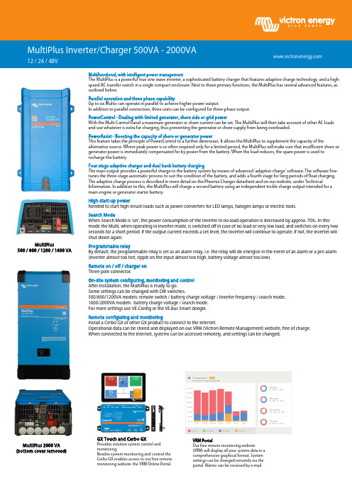
Multifunctional, with intelligent power managementThe MultiPlus is a powerful true sine wave inverter, a sophisticated battery charger that features adaptive charge technology, and a high-speed AC transfer switch in a single compact enclosure. Next to these primary functions, the MultiPlus has several advanced features, asoutlined below.Parallel operation and three phase capabilityUp to six Multis can operate in parallel to achieve higher power output.In addition to parallel connection, three units can be configured for three-phase output.PowerControl - Dealing with limited generator, shore side or grid powerWith the Multi Control Panel a maximum generator or shore current can be set. The MultiPlus will then take account of other AC loads and use whatever is extra for charging, thus preventing the generator or shore supply from being overloaded.PowerAssist - Boosting the capacity of shore or generator powerThis feature takes the principle of PowerControl to a further dimension. It allows the MultiPlus to supplement the capacity of thealternative source. Where peak power is so often required only for a limited period, the MultiPlus will make sure that insufficient shore or generator power is immediately compensated for by power from the battery. When the load reduces, the spare power is used to recharge the battery.Four stage adaptive charger and dual bank battery chargingThe main output provides a powerful charge to the battery system by means of advanced ‘adaptive charge’ software. The software fine-tunes the three-stage automatic process to suit the condition of the battery, and adds a fourth stage for long periods of float charging. The adaptive charge process is described in more detail on the Phoenix Charger datasheet and on our website, under TechnicalInformation. In addition to this, the MultiPlus will charge a second battery using an independent trickle charge output intended for a main engine or generator starter battery.High start-up powerNeeded to start high inrush loads such as power converters for LED lamps, halogen lamps or electric tools.Search ModeWhen Search Mode is ‘on’, the power consumption of the inverter in no-load operation is decreased by approx. 70%. In this mode the Multi, when operating in inverter mode, is switched off in case of no load or very low load, and switches on every two seconds for a short period. If the output current exceeds a set level, the inverter will continue to operate. If not, the inverter will shut down again.Programmable relayBy default, the programmable relay is set as an alarm relay, i.e. the relay will de-energise in the event of an alarm or a pre-alarm (inverter almost too hot, ripple on the input almost too high, battery voltage almost too low).Remote on / off / charger on Three pole connector.On-site system configuring, monitoring and control After installation, the MultiPlus is ready to go. Some settings can be changed with DIP switches.500/800/1200VA models: remote switch / battery charge voltage / inverter frequency / search mode. 1600/2000VA models: battery charge voltage / search mode. For more settings use VE-Config or the VE.Bus Smart dongle.Remote configuring and monitoringInstall a Cerbo GX or other GX product to connect to the internet.Operational data can be stored and displayed on our VRM (Victron Remote Management) website, free of charge. When connected to the internet, systems can be accessed remotely, and settings can be changed.MultiPlus Inverter/Charger 500VA - 2000VA 12 / 24 / 48VMultiPlus500 / 800 / 1200 / 1600 VAMultiPlus 2000 VA (bottom cover removed)GX Touch and Cerbo GXProvides intuitive system control and monitoring.Besides system monitoring and control the Cerbo GX enables access to our free remote monitoring website: the VRM Online Portal.VRM PortalOur free remote monitoring website(VRM) will display all your system data in a comprehensive graphical format. System settings can be changed remotely via the portal. Alarms can be received by e-mail.PowerControl / PowerAssist No Yes Yes Yes YesThree Phase and parallel operation Yes Yes Yes Yes Yes Transfer switch 16 A 16 A 16 A 16 A 35 AInput voltage range 9,5 – 17 V 19 – 33 V 38– 66 VOutput Output voltage: 230VAC ± 2% Frequency: 50Hz ± 0,1% (1)Cont. output power at 25°C (3)500 VA 800 VA 1200 VA 1600 VA 2000 VA Cont. output power at 25°C 430 W 700 W 1000 W 1300 W 1600 W Cont. output power at 40°C 400 W 650 W 900 W 1100 W 1400 W Cont. output power at 65°C 300 W 400 W 600 W 800 W 1000 W Peak power 900 W 1600 W 2400 W 2800 W 3500 W Maximum efficiency 90 / 91 / 92% 92 / 93 / 94% 93 / 94 / 95% 93 / 94 / 95% 93 / 94 / 95% Zero-load power 6 / 6 / 7 W 7 / 7 / 8 W 10 / 9 / 10 W 10 / 9 / 10 W 10 / 9 / 10 W Zero-load power in search mode 2 / 2 / 3 W 2 / 2 / 3 W 3 / 3 / 3 W 3 / 3 / 3 W 3 / 3 / 3 WAC Input Input voltage range: 187-265 VAC Input frequency: 45 – 65 HzCharge voltage 'absorption' 14,4 / 28,8 / 57,6 VCharge voltage 'float' 13,8 / 27,6 / 55,2 VStorage mode 13,2 / 26,4 /52,8 VCharge current house battery (4)20 / 10 / 6 A 35 / 16 / 9 A 50 / 25 / 13 A 70 / 40 / 20 A 80 / 50/ 25 A Charge current starter battery 1A (12 V and 24 V models only)Battery temperature sensor YesProgrammable relay (5)YesProtection (2) a – gVE.Bus communication portFor parallel and three phase operation, remote monitoring and system integration(RJ45-spliter ASS030065510 needed for 500 / 800 / 1200 VA models)Remote on-off On/off/charger only On/offDIP switches Yes(6)Yes(6)Yes(6)Yes(7)Yes (7) Internal DC fuse 125 / 60 /30 A 150 / 80 / 40 A 200 / 100 / 50 A 200 / 125 / 60 A no Common Characteristics Operating temp. range: -40 to +65°C (fan assisted cooling) Humidity (non-condensing): max 95%Common Characteristics Material & Colour: Steel/ABS (blue RAL 5012) Protection category: IP 21 Steel (RAL 5012), IP22 Battery-connection 16 / 10 / 10 mm² 25 / 16 / 10 mm² 35 / 25 / 10 mm² 50 / 35 / 16 mm² M8 bolts230V AC-connection G-ST18i connector Screw Weight 4,4 kg 6,4 kg 8,2 kg 10,2 kg 15,5 kg Dimensions (h x w x d) 311 x 182 x 100 mm 360 x 240 x 100 mm 406 x 250 x 100 mm 470 x 265 x 120 mm 506 x 236 x 147 mmSafety EN-IEC 60335-1, EN-IEC 60335-2-29, EN 62109-1Emission Immunity EN 55014-1, EN 55014-2, EN-IEC 61000-3-2, EN-IEC 61000-3-3, IEC 61000-6-1, IEC 61000-6-2, IEC 61000-6-3Automotive Directive ECE R10-51) Can be adjusted to 60Hz and to 240V2) Protection:a. Output short circuitb. Overloadc. Battery voltage too highd. Battery voltage too lowe. Temperature too highf. 230VAC on inverter outputg. Input voltage ripple too high3) Non-linear load, crest factor 3:14) Up to 25°C ambient5) Programmable relay which can be set for:general alarm, DC under voltage or generator start/stop signal functionAC rating: 230V/4ADC rating: 4A up to 35VDC, 1A up to 60VDC6) Remote / battery charge voltage / inverter frequency / search mode7) Battery charge voltage / search modeBMV-712 Smart BatteryMonitorUse a smartphone or otherBluetooth enabled device to:1.customize settings,2.monitor all important dataon single screen,3.view historical data,4.update the software whennew features becomeavailable.。
3kw逆变器说明书
正弦波逆变器使用说明书型号:WI30-240版本:1.0泰州市伊太尔机电制造有限公司Taizhou Eastyle Mechanical & Electrical Manufacture Co., Ltd.安全注意事项1. 非常感谢您购买为民电源的逆变器,请在安装及使用本产品前仔细阅读使用说明书,并妥善保管。
2. 须有经验的技术人员进行安装操作,安装过程需严格按照本用户使用手册进行,确保该产品能够正常工作。
3. 本产品应避免长期接触腐蚀性气体和潮湿环境。
4. 切勿将本产品放置在潮湿、雨淋、暴晒、严重灰尘、震动、腐蚀及强烈电磁干扰的环境中。
5. 请勿打开本产品外壳自行维修。
目录一、产品概述 (1)二、完善的保护功能 (1)三、应用 (2)四、面板说明 (2)五、安装步骤及注意事项 (3)六、使用环境 (4)七、故障分析 (4)八、技术参数 (5)九、售后服务 (5)一、产品概述该离网型逆变器采用数字化智能控制,核心器件采用功能强大的单片机进行控制,使得外围电路结构简单,控制方式和控制策略灵活强大;功率器件则采用优质的进口器件,从而确保了逆变器优异的性能和稳定性。
该逆变器为正弦波逆变器,相对于方波或修正正弦波(阶梯波)逆变器具有更强的带负载效果和带负载能力。
设备可带感性负载和其它任何类型的通用交流负载,带冰箱、电视机和收音机等设备无干扰和噪音,且不会影响负载设备的性能和寿命。
同时,采用高效率的环形隔离变压器,使得整机逆变效率高,空载损耗低、波形失真小、价格低廉等优点。
二、完善的保护功能三、应用本逆变电源能够将蓄电池中存储的直流电能转变成交流电能,可以作为通信、邮电、交通、家庭等的备用电源;也可用作车、船载电能等。
四、面板说明1、指示灯前面板上的工作指示灯绿灯亮时,表示逆变器处于逆变工作状态。
2、液晶当逆变器处于工作状态时,液晶显示蓄电池电压、输出电压。
当逆变器处于故障状态时,液晶中将显示相应的状态参数,使用户能够直观了解逆变器的工作状态,并可以根据蓄电池的电压来调节使用负载的大小和时间。
逆变器使用说明书

逆变器使用说明书车载逆变器用户手册1、简介感谢您购买HUASYN系列的逆变器。
为了您能舒适、安全的使用本产品,请仔细阅读本说明书,说明书中包含关于本产品的重要信息,请保留此说明书以供以后参考。
HUASYN系列逆变器拥有您所期待的的卓越品质,无论你接在汽车点烟器插孔,还是接在电瓶上,都能直接转换为交流电。
它可广泛用于各类家用电器上,让您在商务工作、驾车旅游、停电应急的时候,给您源源不断的动力。
2、产品特性采用专用智能IC控制逆变器产品,具有非常完善的保护功能和指示功能。
采用优质的双面线路板及电子元件,保证产品的高质量,高性能。
转换效率高、小巧轻便、适用范围广的特点。
产品示意图:75W100W150W200W300W500W3、使用说明a:使用环境基于安全和性能的考虑,HUASYN系列产品应该在以下环境下使用:干燥:不能浸水或淋雨阴凉:环境温度应该在0℃到40℃之间通风:保持壳体上方5CM内无异物,其它端面通风良好,确认风扇不会在工作过程中不会发生阻塞或障碍(适用于有带风扇的产品),以便防止出现通风不良的情况。
b:操作方法1、确定所使用的电器功率应小于所使用的逆变器的额定输出功率。
2、当使用设备输出功率小于200W时,将逆变器开关置于关闭位置,然后雪茄头紧密地插入车内点烟器插口,确保雪茄头良好接触。
3、当使用设备输出功率大于200W时,必须经过鳄鱼夹线使用,引线的太阳端子接至逆变器接线柱,颜色应该匹配,引线端为红色的接逆变器上的红色接线柱,引线端为黑色的接逆变器的黑色接线柱;另外一端的鳄鱼夹连接所使用过的电瓶,红色鳄鱼夹接“+”级,黑色鳄鱼夹接“﹣”级)。
4、输入端接好后,打开开关,逆变器指示灯将发亮,表示已经有交流电输出,逆变器便能够开始正常工作。
5、将需要使用的电器插入的逆变器的输出端AC插座或USB接口充电,根据你所使用的设备选择。
6、开启你的电器开关,HUASYN逆变器便能够给你带来源源不断的交流电能。
逆变器使用说明书
逆变器使用说明书第一章介绍1.1 产品概述逆变器是一种将直流电能转换为交流电能的装置,广泛应用于太阳能、风能等可再生能源系统中。
本使用说明书旨在向用户提供逆变器的正确使用方法和注意事项,以确保产品的安全运行和有效性。
1.2 产品特点我们的逆变器具有以下特点:(1)高效能转换:采用先进的电子技术,将直流电能高效地转换为交流电能;(2)稳定性强:具备过载保护、短路保护、过温保护等功能,保障设备的稳定运行;(3)便捷安装:逆变器体积小巧,重量轻,安装简便;(4)用户友好:操作简单,具备直观的界面显示和功能按钮;(5)可靠性高:采用优质的元器件和严格的生产工艺,确保产品的可靠性和耐用性。
第二章使用前的准备2.1 确认产品完整性在使用逆变器之前,请检查包装内是否包含逆变器本体、电源线、使用说明书等配套物品,并确保产品外观完好无损。
2.2 安装环境准备(1)选择安装位置:逆变器需要在通风良好、干燥、无尘、无腐蚀性气体的环境中安装,避免阳光直射;(2)安装固定:逆变器需要固定在平稳的支架上,确保其稳定性和安全性;(3)电源连接:将逆变器与电源连接,确保电源线接线正确、牢固可靠。
第三章使用方法3.1 启动操作(1)将逆变器的直流输入端与太阳能电池连接,确保连接牢固;(2)将逆变器的交流输出端与负载设备连接,确保连接牢固;(3)按下逆变器的开机按钮,待指示灯亮起表示逆变器已启动。
3.2 参数设置逆变器具备一些可调节的参数,用户可以根据实际需求进行设置。
具体设置方法请参考使用说明书中的“参数设置”章节。
3.3 监测与故障排除逆变器配备了监测功能,可以实时显示逆变器的工作状态和输出功率等信息。
若逆变器出现故障,请参考使用说明书中的“故障排除”章节进行处理。
第四章注意事项4.1 安全使用(1)请勿将逆变器暴露在高温、高湿等恶劣环境中,以免影响逆变器的性能和寿命;(2)请勿将逆变器放置在易燃或易爆物品附近,避免发生火灾或爆炸事故;(3)请勿将逆变器与大功率电器连接,以免损坏逆变器;(4)请勿擅自拆卸逆变器,以免发生意外。
KHF系列1~3KVA逆变器说明书v1.1

用户指南之南宫帮珍创作KHF系列1~3KVA并联逆变器()深圳市科奥信电源技术有限公司Shenzhen Keaoxin PowerSupply Technology Co.,Ltd.本手册为1~3KVA功率品级的KHF逆变器提供需要的装置, 把持和维护技术信息.请务必在把持KHF机器之前阅读此手册, 并请妥善保手册予备用.手册分为两个部份:第一部份—KHF逆变器介绍这部份介绍单相逆变器KHF系列, 包括系统概述、内部组成、选型描述, 及系统规格.第二部份—典范应用此部份分别介绍单机系统、单相并机系统、三相并机组合系统的说明及配置第三部份—装置和把持此部份介绍KHF逆变器的装置和把持信息, 包括系统的总的描述, 其组成部份, 及其功能, 指示控制器的功能描述;以及在正常、应急和维护把持条件下的把持顺序.声明:由于产物和技术的不竭更新、完善,本资料中的内容可能与实际产物不完全相符,敬请谅解.如需查询产物的更新情况, 请联系厂商.目录第一部份 KHF逆变器介绍11.4 主要技术参数21.5.2 数字化LCD (液晶)显示41. 6 后面板控制51.7 机械规格81.7.1 重量81.7.2 结构尺寸81.8 环境条件111.8.1 工作温度111.8.2 非工作温度111.8.4 运行高度111.8.5 噪声111.8.6 冷却11第二部份…典范应用122.1 单机系统122.2 单相并机系统132.3 三相组合系统15第三部份…装置说明及把持173.0 简介173.1 接收173.2 贮存173.3 装置前准备173.4 装置173.4.1 位置选择173.4.2 环境温度173.4.3 冷却173.4.4 固定和线的位置选择173.4.5 接地173.4.6 逆变器连接183.5 逆变器运行18第一部份 KHF逆变器介绍正弦波逆变器通过直流输入电源提供稳定的、无失真的交流电;在商业用电停电的场所为必需工作的敏感设备提供可选输出电压和频率的电压.通过一个静态开关, 逆变器也能够组成一个可靠的和经济型的在线式或后备式不间断电源(UPS), 也可以组成性能可靠的应急电源(EPS).该机型为19英寸, 23英寸或者25英寸的机柜设计, 此系列产物均已模块化, 配用简单灵活.例:KHF 3000 B W 2KHF:产物系列型号(高频逆变系列)3000:标称容量(VA)B:直流输入电压品级(V)A:48V B:220V C:110V D:540VW:机箱结构类型W:卧式 L:立式2:整机工作类型1:纯逆变 2:后备式 3:在线式 4:在线式, 后备式可设, 输出电压、频率可设(单机) 5:逆变放电一体(单机)1.4 主要技术参数表1-2:逆变器主要技术参数项目名称技术指标模块额定输出功率1~3KVA最年夜并联模块数量12个直流输入额定电压(VDC)48/110/220/540电压允许范围(VDC)40~60/95~135/190~270/460~670旁路旁路转换时间电子式≤4mS机械式≤10mS 输入交流电压允许范围(VAC)132~264交流输出额定电压(VAC)220额定频率(Hz)50/60功率因数0.8~负载调整率<1%频率精度<0.1%峰值因数3:1波形失真度阻性满载<3%, 非线形满载<5%效率(额定输入电压, 阻性满载)>80%静态响应(负载0↔100%)电压瞬变范围<5%, 瞬变响应恢复时间≤60mS 并联不均流度<5%额定电流有效值过载能力负载电流<105%, 连续工作负载电流105~125%, 继续10min负载电流125~150%, 继续1min负载电流>150%, 60mS关机环境条件绝缘强度2KVac, 1min噪音(1m)<55dB工作环境温度0~45℃运输与存储温度-40~70℃湿度0~90%, 无冷凝海拔(m)≤3000, 1500~3000m每升高100m输出降额1% 呵护功能输入接反呵护, 输入欠压、过压呵护, 输出过载呵护, 输出短路呵护, 过温呵护1.5前面板控制逆变器的前面板KHF逆变器的前面板如图1所示.整个前面板控制部份如图2所示薄膜开关通风口拉环固定孔液晶显示图1 KHF逆变器的前面板图2KHF逆变器的控制面板左边是滚动开关.按下向上开关, 上一个分歧的读数将显示出来.按下向下开关显示屏将向相反的方向滚动以显示分歧的读数.面板右边是加减开关, 这两个开关用于设置变量的增减调节.还有印有“ON/OFF”, “ESCAPE” , “SILENCE”和“ENTER”字样的按键:.是“开/关机”键, 用于开或关逆变器(此按键只用于单机, 不用于并机)是“取消”键, 用于退出设置界面是“消音”键, 用于停止蜂鸣器鸣叫是“确认”键, 确定所作设置1.5.2数字化LCD(液晶)显示此系列产物都配有自力的LCD液晶显示器件, LCD可以显示两行20个字符, 显示两种信息:系统状态或检丈量.系统状态默认为运行, 接下来是系统故障或关机.每行包括三列, 分别暗示:1) 电源类型;2)电源模式;3)电源状态.电源模式界说如下:"INV."暗示逆变模块, "BYP"暗示旁路装置, 为维修旁路继电器或者静态传输开关.至于电源模式和电源状态信息, 以及相应的LED状态显示器的颜色, 拜会表1-3.第一列第二列第三列电源模式/状态第一行INV ON NORMAL 系统由逆变向负载供电第一行INV OFF DCFLT 直流输入超越正常范围第二行BYP ON NORMAL 系统由旁路向负载供电第二行BYP OFF BYPFLT 交流输入超越正常范围负载电压(伏) 负载百分比(有功功率与视在功率之间取年夜者)旁路电压(伏) 频率(赫兹) 直流输入电压(伏) 负载有功负载电流(安培)状态代码(0000H ):16进制数, 用于故障诊断 要显示检测值, 请按上移或下移按键.1. 6后面板控制KHF 系列中220V 和110V 输入的逆变器的后面板图如图3所示模块的反面设有开关, 对并机系统, 用于设置模块地址. 拨码开关设置如下所示(拨到ON 暗示1, 反之, 暗示0): a.地址拨码的设置要求介入并联的模块必需设置两两分歧的地址, 如果地址相同, 则模块会发作声光报警, 无法并联.通风口航空插座信号线接口拨码开关并机线接口 图3 KHF 逆变器的后面板总共可以设置12个地址, 合法的地址范围为0~11, 如果超越此范围, 模块也会发作声光报警.b.如何设置地址拨码如上图所示, 拨码开关的第1位对应二进制的低位, 第4位对应二进制的高位.拨到ON暗示1, 反之, 暗示0.例如, 在上图中, 二进制0101B, 则设置的模块地址为5.如果是组成三相系统, 则A相模块的地址必需设置在0~3范围内, B相模块的地址必需设置在4~7范围内, C相模块的地址必需设置在8~11范围内. 说明:更改拨码设置时必需重新上电设置才有效.单个逆变模块通过航空插与托架上的线路相连, 托架上的航空插反面正视图如下图4所示:图4 航空插反面正视图航空插孔号颜色接线说明3 蓝N线(市电N和输出N共接)4 黄市电旁路输入L26 黑直流输入负27 红直流输入正28 蓝N线(市电N和输出N共接)29 黄逆变模块输出L线KHF485接交流输出接口通风口口图5 48V输入单机逆变器的后面板图说明:拨码设置与前述拨码设置相同.1.7 机械规格1.7.1 重量2KVA 9KG1.7.2结构尺寸KHF逆变器的结构尺寸是:高:89mm宽:490mm深:390mm 直流输入市电输入拨码创作时间:二零二一年六月三十日创作时间:二零二一年六月三十日KHF 面板外形及开孔尺寸图机箱箱体底面与前面板下边平齐注:此尺寸专门针对我公司的机柜结构, 如果客户自己组屏, 建议根据上图中的模块尺寸来设计开孔,以免呈现偏差.图6 KHF 逆变器的外形及开孔尺寸图1.8环境条件1.8.1 工作温度此系列机型连续过载125%运行最高50摄氏度, .-10 to +50摄氏度之间满载输出到过载125%以及输出短路30秒.+50 and +70摄氏度线形降额到0.1.8.2 非工作温度运输温度-40~+75摄氏度, 但不推荐存储.推荐存储条件见3.2.1.8.3工作湿度0 到90%相对湿度, 无冷凝.1.8.4 运行高度海拔10,000英尺.海拔3300英尺以上, 最高环境温度从50摄氏度每升高1000英尺减小3摄氏度(10,000英尺处30摄氏度最高).1.8.5 噪声小于60 dBA.per Type 2, IEC and ANSI SI.4, 1981标准, 在55 dBA环境中距离任意概况4英尺处丈量.1.8.6 冷却风冷.进风口在前面板, 出风口在柜体外侧.图2.1 逆变模块框图第二部份…典范应用单机系统我公司的每一个逆变模块都是一个自力的交流电源, 能够独自地为负载提供所需的交流电, 所以只需一个模块就可以很方便地组成一个交流供电系统.如图2.2所示, 只要将符合条件的直流电压送到逆变模块的输入端, 模块中的逆变器就可以输出符合用户要求的高质量的恒压恒频交流电压.另外逆变模块中还专门设置了旁路单位, 所以只要将市电引入到逆变模块的旁路输入端, 供电系统就可以根据用户需要以及系统的实际运行状况使得系统的交流输出在逆变电压与市电之间进行切换, 最年夜水平地保证了对用户的不间断供电.也就是说逆变模块的交流输出端提供给用户的既可以是电网电压, 也可以是高质量的逆变电压.本供电系统有逆变输出优先和旁路输出优先两种工作模式,用户可以根据自己的实际需要选择.用户也可以根据自己的实际需要来选择是否将市电引入模块:引入市电, 逆变模块既可以输出电网电压, 也可以输出高质量的逆变电压;不引入市电, 则逆变模块只输出逆变电压.单相并机系统由于单个逆变模块容量有限, 而且不具备冗余能力, 使得供电系统的可靠性不高, 而且不方便用户管理和维修.为了增年夜供电系统的容量, 同时提高系统的可靠性, 往往采纳多个模块组成高可靠度的并联冗余系统.图中所示的就是由n 个逆变模块并联组成的单相供电系统, 其中各模块既可图2.2 单个逆变模块供电系统交流输出直流输入逆变模块市电输入以共用同一路直流输入, 也可以分别采纳独自的直流输入电源供电.这样系统的总容量就为单个逆变模块容量的n倍, 使得系统供电能力年夜增.另外, 如果其中一个或某几个模块故障, 只需将它们拔出, 换上新的模块即可, 而不需要将系统输出断电, 不会造成用户供电的中断.与单个逆变模块组成的供电系统一样, 只要将市电引入到逆变模块的旁路输入端, 供电系统就可以根据用户需要以及系统的实际运行状况使得系统的交流输出在逆变电压与市电之间进行切换, 最年夜水平地保证了对用户的不间断供电.也就是说逆变模块的交流输出端提供给用户的既可以是电网电压, 也可以是高质量的逆变电压.本供电系统有逆变输出优先和旁路输出优先两种工作模式,用户可以根据自己的实际需要选择.在逆变模块并联供电系统中, 如果并联的模块超越3个, 则系统额定输出电流较年夜, 如果用户需要系统输出在市电与逆变电压之间切换, 系统最好配备专门的旁路模块, 以保证系统的供电平安.如图2.4所示.本供电系统有逆变输出优先和旁路输出优先两种工作模式,用户可以根据自己的实际需要, 通过旁路模块很方便地对供电系统工作模式进行设置.如果不设置, 则系统默认为旁路优先工作模式.在配备了旁路模块的系统中, 逆变模块无需引入市电.(1为用户提供交流电.用户可根据自己的需要选择逆变模块的数量, 而且以后还可以通过增加模块个数来很方便地实现供电系统的扩容.用户也可以根据自己的实际需要来选择是否将市电引入模块:引入市电, 逆变模块既可以输出电网电压, 也可以输出高质量的逆变电压;不引入市电, 则逆变模块只输出逆变电压.(2)旁路模块即静态旁路切换开关, 实现供电系统逆变供电和旁路供电两种工作模式的切换.单相系统配置单相旁路模块, 内置有2对双向可控硅.如果供电系统只需要逆变输出或者并联逆变模块不超越3个, 则可以不需要配置旁路模块, 对3个模块以上的并联系统, 如果对切换时间没有很高的要求, 也可以不配旁路模块.为了保证整个供电系统的切换平安, 建议并联系统配置旁路模块.(3)监控系统显示系统以及所有模块的工作状态、工作参数.本系统可以选配我公司的有PMS-ⅢD触摸屏监控;用户也可以根据我们提供的通讯协议来自己设计监控系统;如果供电系统不配备监控, 则系统也能正常工作, 只是各模块只能显示本机的运行状态及运行参数.三相组合系统我公司逆变模块还有一个优势是能很方便地组成三相供电系统, 以满足要求三相供电系统场所的需要, 例如给三相机电供电.图2.5中所示的就是由多个逆变模块组合而成的三相逆变供电系统, 其中各模块既可以共用同一路直流输入, 也可以分别采纳独自的直流输入电源供电.系统中A 、B 、C 三相的输出电压年夜小相等, 但各相的相位则互差120°, 即B 相滞后A 相120°, C 相滞后B 相120°, 从而组成了一个真正的三相供电系统.而在各相中, 既可以由单个逆变模块供电, 也可以采纳多个模块组成可靠性较高的并联冗余系统并增年夜系统的容量.三相组合逆变供电系统还有一个非常突出的优点, 就是带三相不服衡和非线性负载能力强.由于各相的模块独自控制, 彼此之间不受影响, 这样只要所带负载不超越正常范围, 即使是100%不服衡负载, 也不会造成三相输出电压的不服衡和畸变, 从而保证了整个供电系统优良的输出特性, 可以满足各种分歧的三相负载要求.与单相供电系统一样, 只要将电网的三相电压分别引入到各相逆变模块的旁路输入端, 供电系统就可以根据用户需要以及系统的实际运行状况使得系统的交流输出在逆变电压与市电之间进行切换, 最年夜水平地保证了对用户的不间断供电.也就是说逆变模块的交流输出端提供给用户的既可以是电网电压, 也可以是高质量的逆变电压.本供电系统有逆变输出优先和旁路输出优先两种工作模式,用户可以根据自己的实际需要选择.用户可根据自己的需要选择逆变模块的数量, 而且以后还可以通过增加模块个数来很方便地实现供电系统的扩容.如果用户要求三相容量相等, 则每一相的逆变模块数必需相同, 即整个供电系统的逆变模块数为3的倍数.注意:电网的三相电压必需正确地引入到各相逆变模块的旁路输入端, 即A 相电网电压接到A 相逆变模块的旁路输入端, B 相电网电压接到B 相逆变模块的旁路输入端, C 相电网电压接到C 相逆变模块的旁路输入端A相交流输出B相交流输出C相交流输出图2.5 三相组合逆变供电系统在逆变模块三相组合供电系统中, 如果单相并联的模块超越1个, 则系统额定输出电流较年夜, 如果用户需要系统输出在市电与逆变电压之间切换, 系统最好配备专门的旁路模块, 以保证系统的供电平安.本供电系统有逆变输出优先和旁路输出优先两种工作模式,用户可以根据自己的实际需要, 通过旁路模块很方便地对供电系统工作模式进行设置.如果不设置, 则系统默认为旁路优先工作模式.在配备了旁路模块的系统中, 逆变模块无需引入市电.(1为用户提供交流电.用户可根据自己的需要选择逆变模块的数量, 而且以后还可以通过增加模块个数来很方便地实现供电系统的扩容.如果用户要求三相容量相等, 则每一相的逆变模块数必需相同, 即整个供电系统的逆变模块数为3的倍数.用户也可以根据自己的实际需要来选择是否将市电引入模块:引入市电, 逆变模块既可以输出电网电压, 也可以输出高质量的逆变电压;不引入市电, 则逆变模块只输出逆变电压.(2)旁路模块即静态旁路切换开关, 实现供电系统逆变供电和旁路供电两种工作模式的切换.三相系统配置单相旁路模块, 内置有2组6对双向可控硅.如果三相组合供电系统只需要逆变输出或者逆变模块不超越3个, 则可以不需要配置旁路模块, 对3个模块以上的并联组合系统, 如果对切换时间没有很高的要求, 也可以不配旁路模块.为了保证整个供电系统的切换平安, 建议并联系统配置旁路模块.(3)监控系统显示系统以及所有模块的工作状态、工作参数.本系统可以选配我公司的有PMS-ⅢD触摸屏监控;用户也可以根据我们提供的通讯协议来自己设计监控系统;如果供电系统不配备监控, 则系统也能正常工作, 只是各模块只能显示本机的运行状态及运行参数.第三部份…装置说明及把持3.0 简介此部份介绍KHF系列逆变器的接收、贮存以及装置说明.3.1 接收由于运输过程可能造成仪器损坏, 请在接收货运公司方承运的货物时, 检查货物包装是否损坏.如有损坏迹象, 请在接收单上注明.3.2贮存如果仪器需要贮存, 请置于阴凉、干燥、通风处, 而且远离雨水, 腐蚀性化学制品.请用油布或塑料包装将仪器包裹好以防灰尘、污垢、油垢等外来物质.3.3装置前准备胜利的装置KHF需要认真的准备和选址.装置逆变器必需由具有丰富的年夜功率电子设备经验的专业电子工程师来完成.3.4装置逆变器可以装置在19英寸, 23英寸, 25英寸柜中, 具体装置方式取决于装置位置.3.4.1 位置选择此仪器必需装置在良好的工作环境处.主要的考虑因素有:通风、周边环境、易把持.仔细选择装置位置有助于仪器的正常工作.请将仪器装置在清洁、干燥、通风顺畅的位置.3.4.2 环境温度KHF系列的逆变器必需工作于50℃以下的环境温度.3.4.3冷却为了确保仪器良好工作, 当仪器装置在机柜内时, 请确保如下的通风间距:顶部和底部:0.25英寸(6.3mm)前后以及正面:11.50英寸(38.1mm)3.4.4固定和线的位置选择逆变器可以装置在19英寸、23英寸、25英寸机柜内.装置前请确定好输入和输出线的位置.逆变器放在机柜后, 请将模块两正面的螺丝锁上,使之固定.3.4.5接地为了平安和机器的正常工作, 以及减小电磁干扰, 正确的接地是必需的.有一个独自的年夜地接地线必需就近接地(GND).年夜地的接线端子应该尽可能的靠近仪器.3.4.6逆变器连接3.4.6.1直流输入线连接请确保电池的正极连接到BAT+接线端子, 电池的负极连接到BAT-接线端子.3.4.6.2交流输出线连接交流输出端子使用的标识为:“OUT_L”和“OUT_N”.请确保输出的N线连接到OUT_N接线端子, 输出的L线连连接到OUT_L接线端子.3.4.6.3旁路输入线连接当整个系统需要旁路时, 请将电网的L线连接到LINE_L接线端子, 电网的N线连接到LINE_N接线端子.(纯逆变不需要)3.5逆变器运行1. 请参照1.6后面板控制中的微型开关设置模块地址.2. 在模块开机接线前, 先丈量输入电压和主电是否是开机电压范围内.3. 接线:直流从BAT正负端接入, 主电电压从旁路的L, N端接入.4.模块通电后, 设置模块前面板监控地址:单机系统, 地址固定为00, 无需另外设置;并机系统, 对应于1中本模块后面板上微型开关设置好的模块地址, 前面板监控的地址必需与之坚持一致, 否则监控将不能显示模块的工作状态及参数.具体把持是在主页面下按“确认”键, 监控将显示“设置”菜单, 再按“确认”键, 将进入地址设置菜单, 地址为2位10进制数, 通过“+”或“-”键使之与后面板上微型开关设置好的4位16进制模块地址相等, 设置完成后按“↓”键, 监控将显示“保管”选项, 再按下“确认”键, 保管地址设置, 而且监控自动返回主页面.5. 监控进入主页面, 显示模块的工作状态及参数, 具体显示请拜会1.5.2, 可通过前面板上左边的“向上”键或“向下”键显示分歧的读数.6. 按下前面板上的“开/关机”键, 再按下“确定”键, 逆变器开机.在已开机的情况下按下前面板上的“开/关机”键, 再按下“确定”键, 则会关闭逆变器, 但此时如果旁路电压正常则模块将由旁路继续供电.需注意的是模块刚上电时默认为开机状态, 即模块上电后会自动开机, 只得手动关机.7. 开机正常后, 前面板信号灯为绿色并闪烁, 标明模块已有输出.通过前面板的液晶显示屏可以读取模块的运行状态以及各参数.8. 如果前面板信号灯为红色并闪烁, 标明模块存在异常状况无输出.蜂鸣器短鸣, 使显示屏移到“状态代码”显示项, 如果四位16进制数为0001标明是直流输入电压异常, 0008标明是交流输入电压异常, 0009则标明两者都异常, 0002标明模块过温呵护, 0040标明是模块过载关机呵护.蜂鸣器长鸣则断开直流输入与交流输入后再重新上电, 如果现象仍然一样则标明模块存在故障, 请与厂家联系.说明:在所有菜单中, V暗示电压, A暗示电流, %暗示百分比, 0000H暗示16进制代码. 弥补:立式结构图模块尺寸:为标准5U高模块, 长*宽*高:400mm *210mm *222mm创作时间:二零二一年六月三十日。
阳光电源 220V三相系列电力逆变器 说明书

电力逆变器220V三相系列目录SN2203K3D1电力逆变器 (2)SN2205K3D1电力逆变器 (4)SN2207.5K3D1电力逆变器 (6)SN22010K3D1电力逆变器 (9)SN22015K3D1电力逆变器 (11)SN22020K3D1电力逆变器 (14)SN22030K3D1电力逆变器 (17)SN22045K3D1电力逆变器 (20)SN22060K3D1电力逆变器 (23)SN220100K3D1电力逆变器 (26)SN220150K3D1电力逆变器 (29)SN220200K3D1电力逆变器 (32)SN2203K3D1电力逆变器◆产品简介该系列逆变电源专为发电厂、变电站设计,广泛应用于电力系统远动、通信、载波、监控、继电保护以及事故照明,也可为发电厂交流润滑油泵、交流风机、水泵提供不间断电力。
Z◆产品优势利用发电厂或变电站现有的直流屏,加装逆变电源组成电力专用不间断电源,比常规UPS有许多优势:1.利用现有直流屏,避免重复投资,降低系统成本。
2.延长不间断时间,提高供电可靠性。
◆性能特点●采用三菱公司第五代高效IPM电源模块;●CPU选用TI公司生产的高性能2407系列DSP;●控制核心采用四层电路板布置,抗干扰性更好;●将模糊PID控制算法运用于逆变控制,提高了系统输出的动态响应,改善了电能输出质量,THD≤4%;●采用日本进口铁芯的高效变压器,转换效率可达94%;●中英文液晶显示多级菜单,显示内容有:实时参数、状态量、定值参数、定值修改,本机按键操作简单;●智能风扇控制,实现无级调速、降低噪声延长风扇寿命;●通讯接口:RS-232/485,CAN,TCP/IP网络,支持MODBUS协议,所有协议均对用户开放;●本机实时钟和数据记录,可对所有的检测数据,故障状态进行记录;●丰富强大的监控软件,提供友好的安装界面,通过主机实现“遥控、遥测、遥调”控制功能;●主监控画面可以显示设备详细运行参数、告警参数和报警定值;●多样的告警方式可供选择,包括:声、光、短信、邮件等;●安全的权限管理,系统运行人员无误操作可能;●可查询历史记录,生成报表,打印和存档;◆技术参数直流输入输入额定电压(V DC )220输入额定电流(A)15.2输入直流电压允许范围(V DC )180~300工作环境噪音(1米)≤45dB使用环境温度-10℃~+50℃湿度0~90%,不结露使用海拔(m)≤4000(海拔高于1000m 降容使用)重量(Kg)42保护功能输入接反保护、输入欠压保护、输入过压保护、输出过载保护、输出短路保护、过热保护。
特变电工逆变器TS228KTL使用说明书
特变电工逆变器TS228KTL使用说明书逆变器的作用以及原理是一种能够将DC12V直流电转换为和市电相同的AC220V交流电,供一般电器使用,是一种方便的车用电源转换器。
车用逆变器是专为小型用电器生产的逆变器,它是目前最先进的直流——交流转换产品之一。
逆变器的使用方法如下:
1、将转换器放置在平坦的地方,确保开关是关的;
2、将红、黑线分别与转换器的红黑接线柱相连,带夹子的一端分别夹在电瓶的正、负极上(红线夹电瓶正极,黑线夹负极)。
如果使用点烟器插头,则将插头插入点烟器插孔即可;
3、将电器的电源插头插入AC插口;
4、打开转换器开关,即可使用。
拓宝TP310逆变器说明书
拓宝TP310逆变器说明书1、简介感谢您购买拓宝TP310逆变器。
为了您能舒适、安全的使用本产品,请仔细阅读本说明书,说明书中包含关于本产品的重要信息,请保留此说明书以供以后参考。
拓宝TP310逆变器拥有您所期待的卓越品质,无论你接在汽车点烟器插孔,还是接在电瓶上,都能直接转换为交流电。
它可广泛用于各类家用电器上,让您在商务工作、驾车旅游、停电应急的时候,给您源源不断的动力。
2、产品特性采用专用智能IC控制逆变器产品,具有非常完善的保护功能和指示功能。
采用优质的双面线路板及电子元件,保证产品的高质量,高性能。
转换效率高、小巧轻便、适用范围广的特点。
产品示意图: 75W 100W 150W 200W 300W 500W3、使用说明a:使用环境基于安全和性能的考虑,拓宝TP310产品应该在以下环境下使用:干燥:不能浸水或淋雨阴凉:环境温度应该在0℃到40℃之间通风:保持壳体上方5CM内无异物,其它端面通风良好,确认风扇不会在工作过程中不会发生阻塞或障碍(适用于有带风扇的产品),以便防止出现通风不良的情况。
b:操作方法 1、确定所使用的电器功率应小于所使用的逆变器的额定输出功率。
2、当使用设备输出功率小于200W时,将逆变器开关置于关闭位置,然后雪茄头紧密地插入车内点烟器插口,确保雪茄头良好接触。
3、当使用设备输出功率大于200W时,必须通过鳄鱼夹线使用,引线的太阳端子接至逆变器接线柱,颜色应该匹配,引线端为红色的接逆变器上的红色接线柱,引线端为黑色的接逆变器的黑色接线柱;另外一端的鳄鱼夹连接所使用过的电瓶,红色鳄鱼夹接“+”级,黑色鳄鱼夹接“﹣”级)。
4、输入端接好后,打开开关,逆变器指示灯将发亮,表示已经有交流电输出,逆变器便可以开始正常工作。
5、将需要使用的电器插入的逆变器的输出端AC插座或USB接口充电,根据你所使用的设备选择。
6、开启你的电器开关,HUASYN逆变器便可以给你带来源源不断的交流电能。
- 1、下载文档前请自行甄别文档内容的完整性,平台不提供额外的编辑、内容补充、找答案等附加服务。
- 2、"仅部分预览"的文档,不可在线预览部分如存在完整性等问题,可反馈申请退款(可完整预览的文档不适用该条件!)。
- 3、如文档侵犯您的权益,请联系客服反馈,我们会尽快为您处理(人工客服工作时间:9:00-18:30)。
宝丰SGI-500KTL逆变器保护定值单
型号SGI-500KTL 厂家:江苏宝丰新能源科技有限公司
保护名称
保护定值
脱扣时间
保护方式及恢复时间
直流软过压
≥DC950V
0.05s
自动脱开电网,逆变器停机并报警,故障消失自动恢复,连续3次,需重新上电。
直流欠压
≤DC420V
0.05s
自动脱开电网,逆变器待机。
直流输入过流
≥1250A
0.05S
自动脱开电网,逆变器停机并报警,故障消失自动恢复,连续五次,需要重新上电交流输出过流
≥1200A
0.05S
自动脱开电网,逆变器停机并报警,故障消失自动恢复,连续五次,需要重新上电交流电压过压
≥172V(相电压)
0.05S
自动脱开电网,逆变器停机并报警,电网恢复正常,20S后自动恢复并网
交流电压欠压
≤132V(相电压)
0.05S
自动脱开电网,逆变器停机并报警,电网恢复正常,20S后自动恢复并网
交流电压过频
≥50.5Hz
0.05S
自动脱开电网,逆变器停机并报警,电网恢复正常,20S后自动恢复并网
交流电压欠频
≤48Hz
0.05S
自动脱开电网,逆变器停机并报警,电网恢复正常,20S后自动恢复并网
交流电压缺相
电网缺相
0.05S
自动脱开电网,逆变器停机并报警,电网恢复正常,20S后自动恢复并网
散热器过温保护
≥95℃
0.05S
当散热器温度≥90℃,进行温度降载,散热器温度≥95℃,逆变器停机并报警;当散热器温度≤40,逆变器自动恢复并网
三相电流不平衡
≥100A(三相最大差值)
0.05S
自动脱开电网,逆变器停机并报警,20s后逆变器重启,连续五次,需要重新上电
交流直流分量
≥5A
0.05S
自动脱开电网,逆变器停机并报警,20s后逆变器重启,连续五次,需要重新上电
电抗温控开关
≥160℃
0.05S
自动脱开电网,逆变器停机并报警,20s后逆变器重启,连续五次,需要重新上电
网流过载
≥1.1In(In=1070A)
连续2min
自动脱开电网,逆变器停机并报警,20s后逆变器重启,连续五次,需要重新上电交流漏电流
≥2A
0.05S
自动脱开电网,逆变器停机并报警,需要重新上电
交流电流流硬件过流
≥1250A
0.05S
自动脱开电网,逆变器停机并报警,20s后逆变器重启,连续五次,需要重新上电软启动电阻故障
逆变电压≤50Vac
0.05S
自动脱开电网,逆变器停机并报警,20s后逆变器重启,连续五次,需要重新上电。