C4040-225 V9.02(1)
钽电容封装大全及技术参数大全
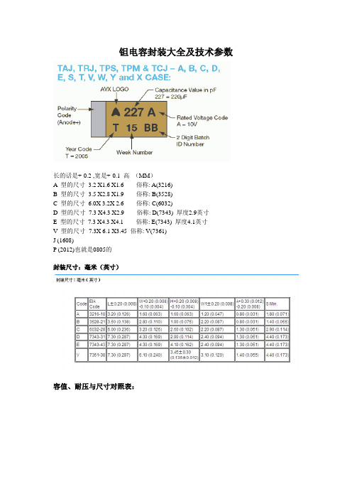
钽电容封装大全及技术参数长的话是+-0.2 ,宽是+-0.1 高(MM)A 型的尺寸3.2 X1.6 X1.6 俗称: A(3216)B 型的尺寸3.5 X2.8 X1.9 俗称: B(3528)C 型的尺寸6.0X 3.2X 2.6 俗称: C(6032)D 型的尺寸7.3 X4.3 X2.9 俗称: D(7343) 厚度2.9英寸E 型的尺寸7.3 X4.3 X4.1 俗称: E(7343) 厚度4.1英寸V 型的尺寸7.3X 6.1 X3.45 俗称: V(7361)J (1608)P (2012)也就是0805的封装尺寸:毫米(英寸)容值、耐压与尺寸对照表:电感封装一般包括贴片与插件。
1.功率电感封装以骨架的尺寸做封装表示。
贴片用椭柱型表示方法如5.8(5.2)×4就表示长径为5.8mm短径为5.2mm高为4mm的电感(贴片电感封装)。
插件用圆柱型表示方法如φ6×8就表示直径为6mm高为8mm的电感。
只是它们的骨架一般要通用,要不就要定造。
2.普通线性电感、色环电感与电阻电容的封装都有一样的表示,贴片用尺寸表示如0603、0805、0402、1206等(贴片电感封装)。
插件用功率表示如1/8W、1/4W、1/2W、1W等。
3.至于二极管插件一般是DO-41;贴片封装就多SOD-214、LL-34。
4.三极管插件一般是To92;贴片封装就多SOT-23、SOT-223等不能尽说,由于自动化封装变得多种多样。
发光二极管:颜色有红、黄、绿、蓝之分,亮度分普亮、高亮、超亮三个等级,常用的封装形式有三类:0805、1206、1210二极管:根据所承受电流的的限度,封装形式大致分为两类,小电流型(如1N4148)封装为1206,大电流型(如IN4007)暂没有具体封装形式,只能给出具体尺寸:5.5 X 3 X 0.5电容:可分为无极性和有极性两类,无极性电容下述两类封装最为常见,即0805、0603;而有极性电容也就是我们平时所称的电解电容,一般我们平时用的最多的为铝电解电容,由于其电解质为铝,所以其温度稳定性以及精度都不是很高,而贴片元件由于其紧贴电路版,所以要求温度稳定性要高,所以贴片电容以钽电容为多,根据其耐压不同,贴片电容又可分为A、B、C、D四个系列,具体分类如下:类型封装形式耐压A 3216 10VB 3528 16VC 6032 25VD 7343 35V拨码开关、晶振:等在市场都可以找到不同规格的贴片封装,其性能价格会根据他们的引脚镀层、标称频率以及段位相关联。
LM4040_05中文资料
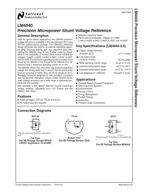
LM4040Precision Micropower Shunt Voltage ReferenceGeneral DescriptionIdeal for space critical applications,the LM4040precision voltage reference is available in the sub-miniature SC70and SOT-23surface-mount package.The LM4040’s advanced design eliminates the need for an external stabilizing capaci-tor while ensuring stability with any capacitive load,thus making the LM4040easy to use.Further reducing design effort is the availability of several fixed reverse breakdown voltages:2.048V,2.500V,3.000V,4.096V,5.000V,8.192V,and 10.000V.The minimum operating current increases from 60µA for the LM4040-2.5to 100µA for the LM4040-10.0.All versions have a maximum operating current of 15mA.The LM4040utilizes fuse and zener-zap reverse breakdown voltage trim during wafer sort to ensure that the prime parts have an accuracy of better than ±0.1%(A grade)at 25˚C.Bandgap reference temperature drift curvature correction and low dynamic impedance ensure stable reverse break-down voltage accuracy over a wide range of operating tem-peratures and currents.Also available is the LM4041with two reverse breakdown voltage versions:adjustable and 1.2V.Please see the LM4041data sheet.Featuresn Small packages:SOT-23,TO-92and SC70n No output capacitor requiredn Tolerates capacitive loadsn Fixed reverse breakdown voltages of 2.048V,2.500V,3.000V,4.096V,5.000V,8.192V,and 10.000VKey Specifications (LM4040-2.5)j Output voltage tolerance(A grade,25˚C)±0.1%(max)j Low output noise(10Hz to 10kHz)35µV rms (typ)j Wide operating current range 60µA to 15mA j Industrial temperature range −40˚C to +85˚C j Extended temperature range −40˚C to +125˚C j Low temperature coefficient100ppm/˚C (max)Applicationsn Portable,Battery-Powered Equipment n Data Acquisition Systems n Instrumentation n Process Controln Energy Management n Product Testing n AutomotivenPrecision Audio ComponentsConnection DiagramsSOT-23TO-92SC7001132301*This pin must be left floating or connected to pin 2.Top ViewSee NS Package Number MF03A (JEDEC Registration TO-236AB)01132303Bottom ViewSee NS Package Number Z03A01132330*This pin must be left floating or connected to pin1.Top ViewSee NS Package Number MAA05AApril 2005LM4040Precision Micropower Shunt Voltage Reference©2005National Semiconductor Corporation Ordering InformationIndustrial Temperature Range (−40˚C to +85˚C)Reverse Breakdown Voltage Tolerance at 25˚C and Average Reverse Breakdown Voltage Temperature CoefficientPackageNS Package NumberM3(SOT-23)M7(SC70)Z (TO-92)Supplied as 1000Units Tape andReelSupplied as 3000Units tape andReelSupplied as 1000Units Tape andReelSupplied as 3000Units Tape andReel±0.1%,100ppm/˚C max (A grade)LM4040AIM3-2.0LM4040AIM3-2.5LM4040AIM3-3.0LM4040AIM3-4.1LM4040AIM3-5.0LM4040AIM3-8.2LM4040AIM3-10.0LM4040AIM3X-2.0LM4040AIM3X-2.5LM4040AIM3X-3.0LM4040AIM3X-4.1LM4040AIM3X-5.0LM4040AIM3X-8.2LM4040AIM3X-10.0LM4040AIZ-2.0LM4040AIZ-2.5LM4040AIZ-3.0LM4040AIZ-4.1LM4040AIZ-5.0LM4040AIZ-8.2LM4040AIZ-10.0MF03A,Z03A±0.2%,100ppm/˚C max (B grade)LM4040BIM3-2.0LM4040BIM3-2.5LM4040BIM3-3.0LM4040BIM3-4.1LM4040BIM3-5.0LM4040BIM3-8.2LM4040BIM3-10.0LM4040BIM3X-2.0LM4040BIM3X-2.5LM4040BIM3X-3.0LM4040BIM3X-4.1LM4040BIM3X-5.0LM4040BIM3X-8.2LM4040BIM3X-10.0LM4040BIM7-2.0LM4040BIM7-2.5LM4040BIM7-3.0LM4040BIM7-4.1LM4040BIM7-5.0LM4040BIM7X-2.0LM4040BIM7X-2.5LM4040BIM7X-3.0LM4040BIM7X-4.1LM4040BIM7X-5.0LM4040BIZ-2.0LM4040BIZ-2.5LM4040BIZ-3.0LM4040BIZ-4.1LM4040BIZ-5.0LM4040BIZ-8.2LM4040BIZ-10.0MF03A,Z03A,MAA05A ±0.5%,100ppm/˚C max (C grade)LM4040CIM3-2.0LM4040CIM3-2.5LM4040CIM3-3.0LM4040CIM3-4.1LM4040CIM3-5.0LM4040CIM3-8.2LM4040CIM3-10.0LM4040CIM3X-2.0LM4040CIM3X-2.5LM4040CIM3X-3.0LM4040CIM3X-4.1LM4040CIM3X-5.0LM4040CIM3X-8.2LM4040CIM3X-10.0LM4040CIM7-2.0LM4040CIM7-2.5LM4040CIM7-3.0LM4040CIM7-4.1LM4040CIM7-5.0LM4040CIM7X-2.0LM4040CIM7X-2.5LM4040CIM7X-3.0LM4040CIM7X-4.1LM4040CIM7X-5.0LM4040CIZ-2.0LM4040CIZ-2.5LM4040CIZ-3.0LM4040CIZ-4.1LM4040CIZ-5.0LM4040CIZ-8.2LM4040CIZ-10.0MF03A,Z03A,MAA05A ±1.0%,150ppm/˚C max (D grade)LM4040DIM3-2.0LM4040DIM3-2.5LM4040DIM3-3.0LM4040DIM3-4.1LM4040DIM3-5.0LM4040DIM3-8.2LM4040DIM3-10.0LM4040DIM3X-2.0LM4040DIM3X-2.5LM4040DIM3X-3.0LM4040DIM3X-4.1LM4040DIM3X-5.0LM4040DIM3X-8.2LM4040DIM3X-10.0LM4040DIM7-2.0LM4040DIM7-2.5LM4040DIM7-3.0LM4040DIM7-4.1LM4040DIM7-5.0LM4040DIM7X-2.0LM4040DIM7X-2.5LM4040DIM7X-3.0LM4040DIM7X-4.1LM4040DIM7X-5.0LM4040DIZ-2.0LM4040DIZ-2.5LM4040DIZ-3.0LM4040DIZ-4.1LM4040DIZ-5.0LM4040DIZ-8.2LM4040DIZ-10.0MF03A,Z03A,MAA05A ±2.0%,150ppm/˚C max (E grade)LM4040EIM3-2.0LM4040EIM3-2.5LM4040EIM3-3.0LM4040EIM3X-2.0LM4040EIM3X-2.5LM4040EIM3X-3.0LM4040EIM7-2.0LM4040EIM7-2.5LM4040EIM7-3.0LM4040EIM7X-2.0LM4040EIM7X-2.5LM4040EIM7X-3.0LM4040EIZ-2.0LM4040EIZ-2.5LM4040EIZ-3.0MF03A,Z03A,MAA05AL M 4040 2Extended Temperature Range(−40˚C to+125˚C)Reverse BreakdownVoltage Tolerance at25˚C and Average Reverse Breakdown Voltage Temperature CoefficientPackageM3(SOT-23) See NS Package Number MF03A±0.5%,100ppm/˚C max(C grade)LM4040CEM3-2.0,LM4040CEM3-2.5,LM4040CEM3-3.0,LM4040CEM3-5.0±1.0%,150ppm/˚C max(D grade)LM4040DEM3-2.0,LM4040DEM3-2.5,LM4040DEM3-3.0,LM4040DEM3-5.0±2.0%,150ppm/˚C max(E grade)LM4040EEM3-2.0,LM4040EEM3-2.5,LM4040EEM3-3.0LM40403SOT-23AND SC70Package Marking InformationOnly three fields of marking are possible on the SOT-23’s and SC70’s small surface.This table gives the meaning of the three fields.Part Marking Field DefinitionRJA SOT-23only First Field:R2A SOT-23only RKA SOT-23only R4A SOT-23only R =Reference R5A SOT-23onlySecond Field:J =2.048V Voltage Option 2=2.500V Voltage OptionR8A SOT-23only K =3.000V Voltage Option R0A SOT-23only4=4.096V Voltage Option RJB R2B 5=5.000V Voltage Option RKB R4B 8=8.192V Voltage Option R5B 0=10.000V Voltage Option R8B SOT-23only R0B SOT-23onlyThird Field:RJC R2C A–E =Initial Reverse Breakdown Voltage or Reference Voltage Tolerance RKC R4C A =±0.1%,B =±0.2%,C =+0.5%,D =±1.0%,E =±2.0%R5C R8C SOT-23only R0C SOT-23onlyRJD R2D RKD R4D R5D R8D SOT-23only R0D SOT-23onlyRJE R2E RKEL M 4040 4Absolute Maximum Ratings(Note1)If Military/Aerospace specified devices are required, please contact the National Semiconductor Sales Office/ Distributors for availability and specifications. Reverse Current20mA Forward Current10mA Power Dissipation(T A=25˚C)(Note2)M3Package306mW Z Package550mW M7Package241mW Storage Temperature−65˚C to+150˚C Lead TemperatureM3PackageVapor phase(60seconds)+215˚C Infrared(15seconds)+220˚C Z PackageSoldering(10seconds)+260˚C ESD SusceptibilityHuman Body Model(Note3)2kVMachine Model(Note3)200V See AN-450“Surface Mounting Methods and Their Effect on Product Reliability”for other methods of soldering surface mount devices.Operating Ratings(Notes1,2) Temperature Range(T min≤T A≤T max) Industrial Temperature Range−40˚C≤T A≤+85˚C Extended Temperature Range−40˚C≤T A≤+125˚C Reverse CurrentLM4040-2.060µA to15mA LM4040-2.560µA to15mA LM4040-3.062µA to15mA LM4040-4.168µA to15mA LM4040-5.074µA to15mA LM4040-8.291µA to15mA LM4040-10.0100µA to15mALM4040-2.0Electrical Characteristics(Industrial Temperature Range)Boldface limits apply for T A=T J=T MIN to T MAX;all other limits T A=T J=25˚C.The grades A and B designate initial Re-verse Breakdown Voltage tolerances of±0.1%and±0.2%,respectively.Symbol Parameter Conditions Typical(Note4)LM4040AIM3LM4040AIZ(Limit)(Note5)LM4040BIM3LM4040BIZLM4040BIM7(Limit)(Note5)Units(Limit)V R Reverse Breakdown Voltage I R=100µA 2.048VReverse Breakdown Voltage Tolerance(Note6)I R=100µA±2.0±4.1mV(max)±15±17mV(max)I RMIN Minimum Operating Current45µA6060µA(max)6565µA(max)∆V R/∆T Average Reverse BreakdownVoltage TemperatureCoefficient(Note6)I R=10mA±20ppm/˚CI R=1mA±15±100±100ppm/˚C(max) I R=100µA±15ppm/˚C∆V R/∆I R Reverse Breakdown VoltageChange with OperatingCurrent Change(Note*NOTARGET FOR*)I RMIN≤I R≤1mA0.3mV0.80.8mV(max)1.0 1.0mV(max) 1mA≤I R≤15mA2.5mV6.0 6.0mV(max)8.08.0mV(max)Z R Reverse DynamicImpedance I R=1mA,f=120Hz,I AC=0.1I R0.3Ω0.80.8Ω(max)e N Wideband Noise I R=100µA35µV rms10Hz≤f≤10kHzLM40405LM4040-2.0Electrical Characteristics (Industrial Temperature Range)(Continued)Boldface limits apply for T A =T J =T MIN to T MAX ;all other limits T A =T J =25˚C.The grades A and B designate initial Re-verse Breakdown Voltage tolerances of ±0.1%and ±0.2%,respectively.Symbol Parameter ConditionsTypical (Note 4)LM4040AIM3LM4040AIZ (Limit)(Note 5)LM4040BIM3LM4040BIZ LM4040BIM7(Limit)(Note 5)Units (Limit)∆V RReverse Breakdown Voltage Long Term Stability t =1000hrs T =25˚C ±0.1˚CI R =100µA 120ppmV HYSTThermal Hysteresis (Note 8)∆T =−40˚C to +125˚C0.08%LM4040-2.0Electrical Characteristics (Industrial Temperature Range)Boldface limits apply for T A =T J =T MIN to T MAX ;all other limits T A =T J =25˚C.The grades C,D and E designate initial Reverse Breakdown Voltage tolerances of ±0.5%,±1.0%and ±2.0%,respectively.SymbolParameterConditionsTypical (Note 4)LM4040CIM3LM4040CIZ LM4040CIM7(Limit)(Note 5)LM4040DIM3LM4040DIZ LM4040DIM7(Limit)(Note 5)LM4040EIM7LM4040EIZ (Limit)(Note 5)Units(Limit)V RReverse Breakdown VoltageI R =100µA 2.048VReverse Breakdown Voltage Tolerance (Note 6)I R =100µA ±10±20±41mV (max)±23±40±60mV (max)I RMINMinimum Operating Current45µA 606565µA (max)657070µA (max)∆V R /∆TAverage Reverse Breakdown Voltage Temperature Coefficient (Note 6)I R =10mA ±20ppm/˚CI R =1mA ±15±100±150±150ppm/˚C (max)I R =100µA±15ppm/˚C ∆V R /∆I RReverse Breakdown Voltage Change with Operating Current Change (Note *NO TARGET FOR *)I RMIN ≤I R ≤1mA 0.3mV 0.8 1.0 1.0mV (max)1.01.21.2mV (max)1mA ≤I R ≤15mA 2.5mV 6.08.08.0mV (max)8.010.010.0mV (max)Z R Reverse Dynamic Impedance I R =1mA,f =120Hz 0.3ΩI AC =0.1I R 0.91.11.1Ω(max)e N Wideband NoiseI R =100µA 35µV rms10Hz ≤f ≤10kHz∆V RReverse Breakdown Voltage Long Term Stability t =1000hrsT =25˚C ±0.1˚C 120ppmI R =100µA V HYSTThermal Hysteresis (Note 8)∆T =−40˚C to +125˚C0.08%L M 4040 6LM4040-2.0Electrical Characteristics(Extended Temperature Range)Boldface limits apply for T A=T J=T MIN to T MAX;all other limits T A=T J=25˚C.The grades C,D and E designate initial Reverse Breakdown Voltage tolerances of±0.5%,±1.0%and±2.0%,respectively.Symbol Parameter Conditions Typical(Note4)LM4040CEM3(Limit)(Note5)LM4040DEM3(Limit)(Note5)LM4040EEM3(Limit)(Note5)Units(Limit)V R Reverse BreakdownVoltageI R=100µA 2.048VReverse Breakdown Voltage Tolerance (Note6)I R=100µA±10±20±41mV(max)±30±50±70mV(max)I RMIN Minimum OperatingCurrent 45µA606565µA(max)687373µA(max)∆V R/∆T Average ReverseBreakdown VoltageTemperatureCoefficient(Note6)I R=10mA±20ppm/˚CI R=1mA±15±100±150±150ppm/˚C(max) I R=100µA±15ppm/˚C∆V R/∆I R Reverse BreakdownVoltage Change withOperating CurrentChange(Note7)I RMIN≤I R≤1mA0.3mV0.8 1.0 1.0mV(max)1.0 1.2 1.2mV(max) 1mA≤I R≤15mA2.5mV6.08.08.0mV(max)8.010.010.0mV(max)Z R Reverse DynamicImpedance I R=1mA,f=120Hz,I AC=0.1I R0.3Ω0.9 1.1 1.1Ω(max)e N Wideband Noise I R=100µA35µV rms10Hz≤f≤10kHz∆V R Reverse BreakdownVoltage Long TermStability t=1000hrsT=25˚C±0.1˚CI R=100µA120ppmV HYST Thermal Hysteresis(Note8)∆T=−40˚C to+125˚C0.08%LM4040-2.5Electrical Characteristics(Industrial Temperature Range)Boldface limits apply for T A=T J=T MIN to T MAX;all other limits T A=T J=25˚C.The grades A and B designate initial Re-verse Breakdown Voltage tolerances of±0.1%and±0.2%,respectively.Symbol Parameter Conditions Typical(Note4)LM4040AIM3LM4040AIZ(Limit)(Note5)LM4040BIM3LM4040BIZLM4040BIM7Limits(Note5)Units(Limit)V R Reverse Breakdown Voltage I R=100µA 2.500VReverse Breakdown Voltage Tolerance(Note6)I R=100µA±2.5±5.0mV(max)±19±21mV(max)I RMIN Minimum Operating Current45µA6060µA(max)6565µA(max)LM40407LM4040-2.5Electrical Characteristics (Industrial Temperature Range)(Continued)Boldface limits apply for T A =T J =T MIN to T MAX ;all other limits T A =T J =25˚C.The grades A and B designate initial Re-verse Breakdown Voltage tolerances of ±0.1%and ±0.2%,respectively.Symbol Parameter ConditionsTypical (Note 4)LM4040AIM3LM4040AIZ (Limit)(Note 5)LM4040BIM3LM4040BIZ LM4040BIM7Limits (Note 5)Units (Limit)∆V R /∆TAverage Reverse Breakdown Voltage Temperature Coefficient (Note 6)I R =10mA ±20ppm/˚CI R =1mA ±15±100±100ppm/˚C (max)I R =100µA±15ppm/˚C ∆V R /∆I R Reverse Breakdown Voltage Change with Operating Current Change (Note 7)I RMIN ≤I R ≤1mA0.3mV0.80.8mV (max)1.01.0mV (max)1mA ≤I R ≤15mA2.5mV 6.0 6.0mV (max)8.08.0mV (max)Z R Reverse Dynamic Impedance I R =1mA,f =120Hz,I AC =0.1I R 0.3Ω0.80.8Ω(max)e N Wideband NoiseI R =100µA 35µV rms10Hz ≤f ≤10kHz∆V RReverse Breakdown Voltage Long Term Stability t =1000hrs T =25˚C ±0.1˚CI R =100µA 120ppmV HYSTThermal Hysteresis (Note 8)∆T =−40˚C to +125˚C0.08%LM4040-2.5Electrical Characteristics (Industrial Temperature Range)Boldface limits apply for T A =T J =T MIN to T MAX ;all other limits T A =T J =25˚C.The grades C,D and E designate initial Reverse Breakdown Voltage tolerances of ±0.5%,±1.0%and ±2.0%,respectively.SymbolParameterConditionsTypical (Note 4)LM4040CIM3LM4040DIZ LM4040CIM7Limits (Note 5)LM4040DIM3LM4040DIZ LM4040DIM7Limits (Note 5)LM4040EIM7LM4040EIZ Limits(Note 5)Units(Limit)V RReverse Breakdown VoltageI R =100µA 2.500VReverse Breakdown Voltage Tolerance (Note 6)I R =100µA ±12±25±50mV (max)±29±49±74mV (max)I RMINMinimum Operating Current45µA 606565µA (max)657070µA (max)∆V R /∆TAverage Reverse Breakdown Voltage TemperatureCoefficient(Note 6)I R =10mA ±20ppm/˚C I R =1mA ±15±100±150±150ppm/˚C (max)I R =100µA±15ppm/˚CL M 4040 8LM4040-2.5Electrical Characteristics(Industrial Temperature Range)(Continued)Boldface limits apply for T A=T J=T MIN to T MAX;all other limits T A=T J=25˚C.The grades C,D and E designate initial Reverse Breakdown Voltage tolerances of±0.5%,±1.0%and±2.0%,respectively.Symbol Parameter Conditions Typical(Note4)LM4040CIM3LM4040DIZLM4040CIM7Limits(Note5)LM4040DIM3LM4040DIZLM4040DIM7Limits(Note5)LM4040EIM7LM4040EIZLimits(Note5)Units(Limit)∆V R/∆I R Reverse BreakdownVoltage Change withOperating CurrentChange(Note7)I RMIN≤I R≤1mA0.3mV0.8 1.0 1.0mV(max)1.0 1.2 1.2mV(max) 1mA≤I R≤15mA2.5mV6.08.08.0mV(max)8.010.010.0mV(max)Z R Reverse DynamicImpedance I R=1mA,f=120Hz0.3ΩI AC=0.1I R0.9 1.1 1.1Ω(max)e N Wideband Noise I R=100µA35µV rms10Hz≤f≤10kHz∆V R Reverse BreakdownVoltage Long TermStability t=1000hrsT=25˚C±0.1˚C120ppm I R=100µAV HYST Thermal Hysteresis(Note8)∆T=−40˚C to+125˚C0.08%LM4040-2.5Electrical Characteristics(Extended Temperature Range)Boldface limits apply for T A=T J=T MIN to T MAX;all other limits T A=T J=25˚C.The grades C,D and E designate initial Reverse Breakdown Voltage tolerances of±0.5%,±1.0%and±2.0%,respectively.Symbol Parameter Conditions Typical(Note4)LM4040CEM3Limits(Note5)LM4040DEM3Limits(Note5)LM4040EEM3Limits(Note5)Units(Limit)V R Reverse BreakdownVoltageI R=100µA 2.500VReverse Breakdown VoltageTolerance(Note6)I R=100µA±12±25±50mV(max)±38±63±88mV(max)I RMIN Minimum OperatingCurrent 45µA606565µA(max)687373µA(max)∆V R/∆T Average ReverseBreakdown VoltageTemperatureCoefficient(Note6)I R=10mA±20ppm/˚CI R=1mA±15±100±150±150ppm/˚C(max) I R=100µA±15ppm/˚C∆V R/∆I R Reverse BreakdownVoltage Change withOperating CurrentChange(Note7)I RMIN≤I R≤1mA0.3mV0.8 1.0 1.0mV(max)1.0 1.2 1.2mV(max)1mA≤I R≤15mA 2.5mV6.08.08.0mV(max)8.010.010.0mV(max)LM40409LM4040-2.5Electrical Characteristics (Extended Temperature Range)(Continued)Boldface limits apply for T A =T J =T MIN to T MAX ;all other limits T A =T J =25˚C.The grades C,D and E designate initial Reverse Breakdown Voltage tolerances of ±0.5%,±1.0%and ±2.0%,respectively.SymbolParameterConditionsTypical (Note 4)LM4040CEM3Limits (Note 5)LM4040DEM3Limits (Note 5)LM4040EEM3Limits (Note 5)Units(Limit)Z R Reverse Dynamic Impedance I R =1mA,f =120Hz,I AC =0.1I R 0.3Ω0.91.11.1Ω(max)e N Wideband NoiseI R =100µA 35µV rms10Hz ≤f ≤10kHz∆V RReverse Breakdown Voltage Long Term Stabilityt =1000hrsT =25˚C ±0.1˚CI R =100µA 120ppmV HYSTThermal Hysteresis(Note 8)∆T =−40˚C to +125˚C0.08%LM4040-3.0Electrical Characteristics (Industrial Temperature Range)Boldface limits apply for T A =T J =T MIN to T MAX ;all other limits T A =T J =25˚C.The grades A and B designate initial Re-verse Breakdown Voltage tolerances of ±0.1%and ±0.2%,respectively.Symbol Parameter ConditionsTypical (Note 4)LM4040AIM3LM4040AIZ (Limit)(Note 5)LM4040BIM3LM4040BIZ LM4040BIM7Limits (Note 5)Units (Limit)V R Reverse Breakdown Voltage I R =100µA 3.000VReverse Breakdown Voltage Tolerance (Note 6)I R =100µA ±3.0±6.0mV (max)±22±26mV (max)I RMINMinimum Operating Current47µA 6262µA (max)6767µA (max)∆V R /∆TAverage Reverse Breakdown Voltage Temperature Coefficient (Note 6)I R =10mA ±20ppm/˚C I R =1mA ±15±100±100ppm/˚C (max)I R =100µA±15ppm/˚C ∆V R /∆I R Reverse Breakdown Voltage Change with Operating Current Change (Note 7)I RMIN ≤I R ≤1mA0.6mV0.80.8mV (max)1.11.1mV (max)1mA ≤I R ≤15mA2.7mV 6.0 6.0mV (max)9.09.0mV (max)Z R Reverse Dynamic Impedance I R =1mA,f =120Hz,I AC =0.1I R 0.4Ω0.90.9Ω(max)e N Wideband NoiseI R =100µA 35µV rms10Hz ≤f ≤10kHz∆V RReverse Breakdown Voltage Long Term Stability t =1000hrs T =25˚C ±0.1˚CI R =100µA 120ppmV HYSTThermal Hysteresis (Note 8)∆T =−40˚C to +125˚C0.08%L M 4040 10LM4040-3.0Electrical Characteristics(Industrial Temperature Range)Boldface limits apply for T A=T J=T MIN to T MAX;all other limits T A=T J=25˚C.The grades C,D and E designate initial Reverse Breakdown Voltage tolerances of±0.5%,±1.0%and±2.0%,respectively.Symbol Parameter Conditions Typical(Note4)LM4040CIM3LM4040DIZLM4040CIM7Limits(Note5)LM4040DIM3LM4040DIZLM4040DIM7Limits(Note5)LM4040EIM7LM4040EIZLimits(Note5)Units(Limit)V R Reverse BreakdownVoltageI R=100µA 3.000VReverse Breakdown Voltage Tolerance (Note6)I R=100µA±15±30±60mV(max)±34±59±89mV(max)I RMIN Minimum OperatingCurrent 45µA606565µA(max)657070µA(max)∆V R/∆T Average ReverseBreakdown VoltageTemperatureCoefficient(Note6)I R=10mA±20ppm/˚CI R=1mA±15±100±150±150ppm/˚C(max) I R=100µA±15ppm/˚C∆V R/∆I R Reverse BreakdownVoltage Change withOperating CurrentChange(Note7)I RMIN≤I R≤1mA0.4mV0.8 1.1 1.1mV(max)1.1 1.3 1.3mV(max) 1mA≤I R≤15mA2.7mV6.08.08.0mV(max)9.011.011.0mV(max)Z R Reverse DynamicImpedance I R=1mA,f=120Hz0.4ΩI AC=0.1I R0.9 1.2 1.2Ω(max)e N Wideband Noise I R=100µA35µV rms10Hz≤f≤10kHz∆V R Reverse BreakdownVoltage Long TermStability t=1000hrsT=25˚C±0.1˚C120ppm I R=100µAV HYST Thermal Hysteresis(Note8)∆T=−40˚C to+125˚C0.08%LM4040-3.0Electrical Characteristics(Extended Temperature Range)Boldface limits apply for T A=T J=T MIN to T MAX;all other limits T A=T J=25˚C.The grades C,D and E designate initial Reverse Breakdown Voltage tolerances of±0.5%,±1.0%and±2.0%,respectively.Symbol Parameter Conditions Typical(Note4)LM4040CEM3Limits(Note5)LM4040DEM3Limits(Note5)LM4040EEM3Limits(Note5)Units(Limit)V R Reverse BreakdownVoltageI R=100µA 3.000VReverse Breakdown VoltageTolerance(Note6)I R=100µA±15±30±60mV(max)±45±75±105mV(max)I RMIN Minimum OperatingCurrent 47µA626767µA(max)707575µA(max)LM4040LM4040-3.0Electrical Characteristics (Extended Temperature Range)(Continued)Boldface limits apply for T A =T J =T MIN to T MAX ;all other limits T A =T J =25˚C.The grades C,D and E designate initial Reverse Breakdown Voltage tolerances of ±0.5%,±1.0%and ±2.0%,respectively.SymbolParameterConditionsTypical (Note 4)LM4040CEM3Limits (Note 5)LM4040DEM3Limits (Note 5)LM4040EEM3Limits (Note 5)Units(Limit)∆V R /∆TAverage Reverse Breakdown Voltage TemperatureCoefficient (Note 6)I R =10mA ±20ppm/˚CI R =1mA ±15±100±150±150ppm/˚C (max)I R =100µA±15ppm/˚C ∆V R /∆I R Reverse Breakdown Voltage Change with Operating Current Change (Note 7)I RMIN ≤I R ≤1mA0.4mV 0.8 1.1 1.1mV (max)1.11.31.3mV (max)1mA ≤I R ≤15mA2.7mV 6.08.08.0mV (max)9.011.011.0mV (max)Z R Reverse Dynamic Impedance I R =1mA,f =120Hz,I AC =0.1I R 0.4Ω0.91.21.2Ω(max)e N Wideband NoiseI R =100µA 35µV rms10Hz ≤f ≤10kHz∆V RReverse Breakdown Voltage Long Term Stabilityt =1000hrsT =25˚C ±0.1˚CI R =100µA 120ppmV HYSTThermal Hysteresis(Note 8)∆T =−40˚C to +125˚C0.08%LM4040-4.1Electrical Characteristics (Industrial Temperature Range)Boldface limits apply for T A =T J =T MIN to T MAX ;all other limits T A =T J =25˚C.The grades A and B designate initial Re-verse Breakdown Voltage tolerances of ±0.1%and ±0.2%,respectively.SymbolParameterConditionsTypical (Note 4)LM4040AIM3LM4040AIZ Limits (Note 5)LM4040BIM3LM4040BIZ LM4040BIM7Limits (Note 5)Units (Limit)V R Reverse Breakdown Voltage I R =100µA 4.096VReverse Breakdown Voltage Tolerance (Note 6)I R =100µA ±4.1±8.2mV (max)±31±35mV (max)I RMINMinimum Operating Current50µA 6868µA (max)7373µA (max)∆V R /∆TAverage Reverse Breakdown Voltage Temperature Coefficient(Note 6)I R =10mA ±30ppm/˚C I R =1mA ±20±100±100ppm/˚C (max)I R =100µA±20ppm/˚C ∆V R /∆I R Reverse Breakdown Voltage Change with Operating Current Change (Note 7)I RMIN ≤I R ≤1mA0.5mV0.90.9mV (max)1.21.2mV (max)1mA ≤I R ≤15mA3.0mV 7.07.0mV (max)10.010.0mV (max)L M 4040LM4040-4.1Electrical Characteristics(Industrial Temperature Range)(Continued)Boldface limits apply for T A=T J=T MIN to T MAX;all other limits T A=T J=25˚C.The grades A and B designate initial Re-verse Breakdown Voltage tolerances of±0.1%and±0.2%,respectively.Symbol Parameter Conditions Typical(Note4)LM4040AIM3LM4040AIZLimits(Note5)LM4040BIM3LM4040BIZLM4040BIM7Limits(Note5)Units(Limit)Z R Reverse DynamicImpedance I R=1mA,f=120Hz,0.5ΩI AC=0.1I R 1.0 1.0Ω(max)e N Wideband Noise I R=100µA80µV rms10Hz≤f≤10kHz∆V R Reverse Breakdown VoltageLong Term Stability t=1000hrsT=25˚C±0.1˚CI R=100µA120ppmV HYST Thermal Hysteresis(Note8)∆T=−40˚C to+125˚C0.08%LM4040LM4040-4.1Electrical Characteristics (Industrial Temperature Range)Boldface limits apply for T A =T J =T MIN to T MAX ;all other limits T A =T J =25˚C.The grades C and D designate initial Re-verse Breakdown Voltage tolerances of ±0.5%and ±1.0%,respectively.SymbolParameterConditionsTypical (Note 4)LM4040CIM3LM4040CIZ LM4040CIM7Limits (Note 5)LM4040DIM3LM4040BIZ LM4040DIM7Limits (Note 5)Units (Limit)V R Reverse Breakdown Voltage I R =100µA 4.096VReverse Breakdown Voltage Tolerance (Note 6)I R =100µA ±20±41mV (max)±47±81mV (max)I RMINMinimum Operating Current50µA 6873µA (max)7378µA (max)∆V R /∆T Average Reverse Breakdown Voltage Temperature Coefficient (Note 6)I R =10mA±30ppm/˚C I R =1mA ±20±100±150ppm/˚C (max)I R =100µA ±20ppm/˚C ∆V R /∆I R Reverse Breakdown Voltage Change with Operating Current Change (Note 7)I RMIN ≤I R ≤1mA 0.5mV0.9 1.2mV (max)1.21.5mV (max)1mA ≤I R ≤15mA3.0mV 7.09.0mV (max)10.013.0mV (max)Z R Reverse Dynamic Impedance I R =1mA,f =120Hz,0.5ΩI AC =0.1I R 1.01.3Ω(max)e N Wideband NoiseI R =100µA 80µV rms 10Hz ≤f ≤10kHz∆V RReverse Breakdown Voltage Long Term Stability t =1000hrs T =25˚C ±0.1˚CI R =100µA 120ppmV HYSTThermal Hysteresis (Note 8)∆T =−40˚C to +125˚C0.08%L M 4040LM4040-5.0Electrical Characteristics(Industrial Temperature Range)Boldface limits apply for T A=T J=T MIN to T MAX;all other limits T A=T J=25˚C.The grades A and B designate initial Re-verse Breakdown Voltage tolerances of±0.1%and±0.2%,respectively.Symbol Parameter Conditions Typical(Note4)LM4040AIM3LM4040AIZLimits(Note5)LM4040BIM3LM4040BIZLM4040BIM7Limits(Note5)Units(Limit)V R Reverse Breakdown Voltage I R=100µA 5.000VReverse Breakdown Voltage Tolerance(Note6)I R=100µA±5.0±10mV(max)±38±43mV(max)I RMIN Minimum Operating Current54µA7474µA(max)8080µA(max)∆V R/∆T Average Reverse Breakdown Voltage TemperatureCoefficient(Note6)I R=10mA±30ppm/˚CI R=1mA±20±100±100ppm/˚C(max) I R=100µA±20ppm/˚C∆V R/∆I R Reverse Breakdown VoltageChange with OperatingCurrent Change(Note7)I RMIN≤I R≤1mA0.5mV1.0 1.0mV(max)1.4 1.4mV(max) 1mA≤I R≤15mA 3.5mV8.08.0mV(max)12.012.0mV(max)Z R Reverse DynamicImpedance I R=1mA,f=120Hz,0.5ΩI AC=0.1I R 1.1 1.1Ω(max)e N Wideband Noise I R=100µA80µV rms10Hz≤f≤10kHz∆V R Reverse Breakdown VoltageLong Term Stability t=1000hrsT=25˚C±0.1˚C120ppm I R=100µAV HYST Thermal Hysteresis(Note8)∆T=−40˚C to+125˚C0.08%LM4040。
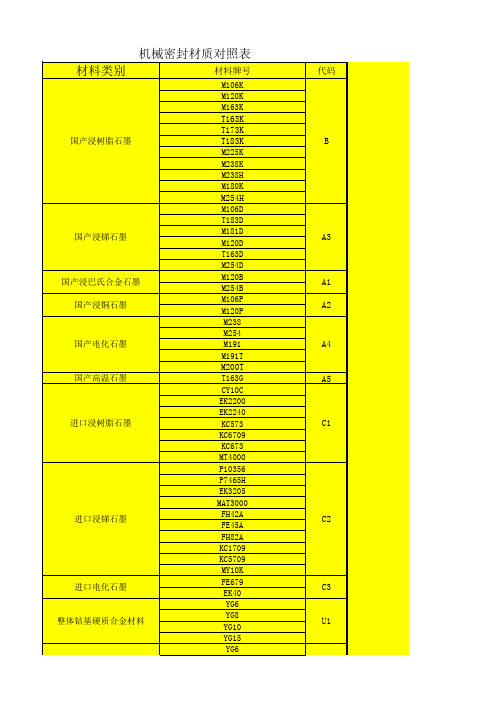
机械密封材质代码表(1)
V2
AFLAS
V3
NBR(丁腈橡胶)
P
HNBR(氢化丁腈)
P1
IIR(丁基橡胶)
B
EPDM(三元乙丙橡胶)
E
四氟材料 全氟醚橡胶
VMQ (硅橡胶)
S
FVMQ(氟硅胶)
S1
CR(氯丁橡胶)
N1
氯醇橡胶
N2
全包覆塑胶
M1
PTFE
T
进口PTFE
T1
PTFE+金属(316或哈氏合金)
Y4
双层PTFE包FKM
G3
321
F
KY704(C4钢,00Cr14Ni14Si4)
G4
Q215A
碳钢 有色金属
Q235A
20#
D
30#
35#
45#
T2(紫铜)
N
H62(黄铜)
N1
ZCuAl10Fe3(ZQAl9-4)(锡青铜)
ZCuSn10P1(ZQSn10-1)(锡青铜) N2
ZQSn6-6-3(锡青铜)
TA2
T1
L2(O态)(纯铝)
T1
ELGILOY
X
1Cr13
2Cr13
3Cr13
E
4Cr13
9Cr18
Q245
D0
30CrMo
35CrMo 38CrMoAl
D1
40Cr
GCr15
D2
65Mn 65钢 60Si2Mn
D3
V
PTFE填玻纤
Y1
PTFE填玻纤+铜
4F材料
PTFE填碳纤+铜(+石墨)
PTFE填铜
PTFE填石墨
CM402培训教材
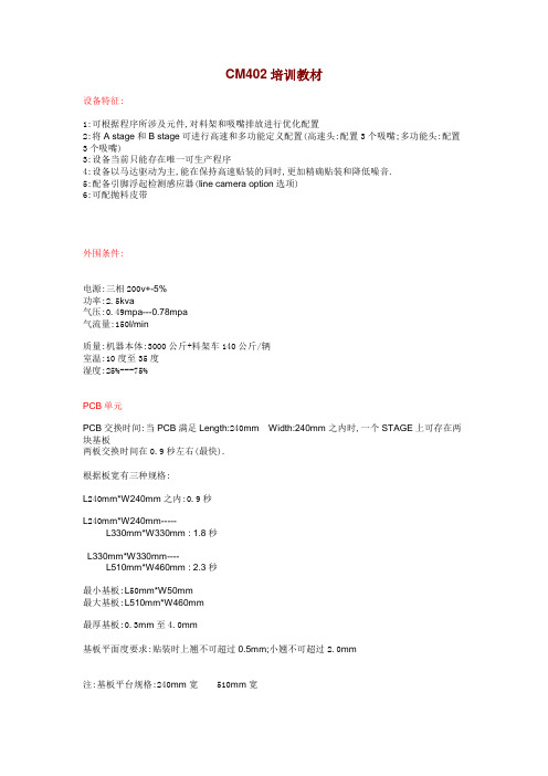
CM402培训教材设备特征:1:可根据程序所涉及元件,对料架和吸嘴排放进行优化配置2:将A stage和B stage可进行高速和多功能定义配置(高速头:配置3个吸嘴;多功能头:配置3个吸嘴)3:设备当前只能存在唯一可生产程序4:设备以马达驱动为主,能在保持高速贴装的同时,更加精确贴装和降低噪音.5:配备引脚浮起检测感应器(line camera option选项)6:可配抛料皮带外围条件:电源:三相200v+-5%功率:2.5kva气压:0.49mpa---0.78mpa气流量:150l/min质量:机器本体:3000公斤+料架车140公斤/辆室温:10度至35度湿度:25%---75%PCB单元PCB交换时间:当PCB满足Length:240mm Width:240mm之内时,一个STAGE上可存在两块基板两板交换时间在0.9秒左右(最快).根据板宽有三种规格:L240mm*W240mm之内:0.9秒L240mm*W240mm-----L330mm*W330mm : 1.8秒L330mm*W330mm----L510mm*W460mm : 2.3秒最小基板:L50mm*W50mm最大基板:L510mm*W460mm最厚基板:0.3mm至4.0mm基板平面度要求:贴装时上翘不可超过0.5mm;小翘不可超过2.0mm注:基板平台规格:240mm宽 510mm宽NOZZLE UNIT单元高速贴装头:每个nozzle unit单元配有独立的伺幅马达多功能头:每个nozzle unit单元配有独立的VCM电机,且可实时监控吸嘴表面所承担压力(规格从0.5N至28N)贴装速度:高速贴装头:0.06秒/片(chip)多功能 :0.18s/chip料架单元:马达式料架:精度更高共有五种型号:8mm ( double feeder)12mm+16mm(共用型)24mm+32mm(共用型)44mm+56mm(共用型)72mm料架设备同时可一次性安装料架数量可达:108(27*4)双料架,可同时有216卷元件安装设备支持料架车:使机种切换更加便捷快速适用元件:0603(公制)----精度:高速头:+-100um 窄间矩:0.05mm 0603至24mm*24mm Thickness:6.5mm 多功能:+-70um 窄间距:0.035mm 0603至100mm*90mmThickness:21mm 质量:30克最小脚间距:高速头:0.65mm (最小)多功能:0.40mm (最小)BGA:最小球间距:1.0mm最小球经:0.5mmCSP:最小球间距:0.5mm最小球经:0.25mmCONNECTOR:最小脚间距:高速 0.65mm多功能:0.5mm外围尺寸: 高速:24mm*24mm之内多功能:100mm长之内,90mm宽之内吸嘴单元:高速吸嘴型号最小对应元件反射板205 0603 标准型号110 1005 标准型号115 1608 标准型号120 2125 标准型号130 3216 标准型号140 直径为3mm 标准型号;配橡胶头450 直径为6mm 大型;配橡胶头460 直径为10mm 大型;配橡胶头(其中:除205吸嘴为采用反射识别模式之外,其余型号透射和反射皆可) 多功能:吸嘴型号对应元件反射板1001 1005/ss-mini tr--2125 标准型号,黑色1002 3216/小型铝电解电容标准型号,黑色1003 对于尺寸相当元件,无限制标准型号,黑色1004 对于尺寸相当元件,无限制标准型号,黑色1005 对于尺寸相当元件,无限制标准型号,黑色1006 23mm*23mm至38mm*38mm 标准型号,黑色吸嘴库设定:NOZZLE:吸嘴序号RECOG MODE:识别模式,由机器自动判断MAX:厂商可提供吸嘴最大数量TUPH:从吸嘴顶部至吸曲面的高度MAXH:吸嘴总高度,可支持吸取表面低于元件表面的吸嘴X:x方向吸嘴的长度Y:y方向吸嘴的长度NAME:吸嘴名称CO:是否支持中心矫正LO:是否可以进行吸嘴吸取位置的教示TO:是否可以进行热补偿VU:真空起始时间:从真空打开到工作头下降到元件吸取高度动作完成的时间VD:真空破坏时间:从真空破坏开始到工作头下降到元件贴装高度的时间TT:吸取保持时间:表示工作头吸取元件时在最低位置的停留时间MT:贴装保持时间:表示工作头贴装元件时在最低位置的停留时间VA1:真空检测传感器判断吸着和贴装发生错误时压力判断(只适用于40系列)VA2:通过真空检测传感器检查到的头内过滤器受阻塞的数值COMMENT:补充说明料架库设定:其中发送计数:表示进给一个元件需要料架动作次数可获最大值:在数据优化时使用的料架数量将不会超过该数目,通常设定为:500同吸条件:1.供料角度一致2.料架类型相同(如为粘编带/散装料则不能同吸)3.视野深度条件:由于camera焦距条件限制,需要被一个nozzle unit上所有的6个nozzle同时吸取时,元件的高度差(最高元件和最低元件的差值)应该1.5mm以内.3.吸取高度差:110:0.10mm115:0.20mm>=120:0.25mm或以下元件识别条件:要满足同吸条件时,6个同时被吸取的元件应当采用相同的识别方式:同为透射,或同为反射,或同为BGA识别方式。
螺纹基本尺寸及公差

螺纹基本尺寸及公差浙江苏强格液压有限公司质量作业文件产品代号规则Q/SQ-G8.4-031 过渡接头编号规则1.1 直通过渡接头编号规则直通过渡接头型号左端标号右端标号直通过渡接头型号中的第一位为数字,表示两端内外螺纹的组合情况;第二、三位为字母,分别表示左右端的结构型式,当左右端结构型式相同时,则使用一位字母,当左右端标号相同时,也使用一组标号。
1.1.1 型号中的第一位数字的含义如下表1 外螺纹/外螺纹 6 过板接头(右端过板)1 法兰/对接式焊接头 7 固定内螺纹/固定内螺纹(无螺母或插入焊)2 外螺纹/活动内螺纹(活动螺母) 8 锁母3 活动内螺纹/活动内螺纹 9 内螺纹堵头4 外螺纹堵头.堵板5 外螺纹/固定内螺纹5 外螺纹/较短焊接管1.1.2 型号中第二、三位字母的含义如下表A 英管螺纹球面 M 公制60?锥面或六角端面组合垫密封B 英管螺纹60?锥面或六角端面组合垫密封 N 美制布锥管C 公制24?轻系列 O 美制SAE O-Ring BOSSD 公制24?重系列 P 美制SAE 90?E 公制平面带O形圈 Q 公制74?F 美制ORFS平面 S 日式英管螺纹60?外锥G 英管螺纹平面、O-Ring密封 T 英锥管螺纹H 公制六角端面O-Ring密封 U NPSMI 710xx系列国标公制铰接体 W 焊接管J 美制JIC 74? X 表示与软管相连用卡环固定K 公制螺纹60?外锥(小松) Y 矿用接头(SAE标准)L 公制组合垫圈密封 Z BSP平面用组合垫密封1Q/SQ-G8.4-031.1.3 左右端标号根据左右端头部的螺纹或尺寸大小定,如下表:英管G1/8” G1/4” G3/8” G1/2” G5/8” G3/4” G1.1/4” G1.1/2” --G1”x11 G2”x11 螺纹 x28 x19 x19 x14 x14 x14 x11 x11 英锥管R1/8”R1/4” R3/8” R1/2” R3/4” R1.1/4” R1.1/2” -- -- R1”x11 R2”x11 螺纹x28 x19 x19 x14 x14 x11 x11 布锥管Z1/8” Z1/4” Z3/8” Z1/2” Z3/4”Z1.1/4” Z1.1/2” Z2” -- Z1”x11.5 螺纹 x27 x18 x18 x14 x14 x11.5 x11.5 x11.5 美制JIC 7/16” 1/2” 9/16” 3/4” 7/8” 1.1/16” 1.5/16” 1.5/8”1.7/8”2.1/2” -- 螺纹 x20 x20 x18 x16 x14 x12 x12 x12 x12 x12 美制ORFS9/16” 11/16” 13/16” 1” 1.3/16” 1.7/16” 1.11/16” 2” -- -- -- 螺纹 x18 x16 x16 x14 x12 x12 x12 x12 美制SAE5/8” 1.1/16” 螺纹 x18 x14 法兰1/2“ 5/8“ 3/4“ 1“ 1.1/4“ 1.1/2“ 2“ 插装式 04 06 08 12 16 20 24 32 标号 02 04 05 06 08 10 12 16 20 24 32 注:公制螺纹的标号按螺纹外径,卡套式直管的标号按直管外径。
CC4040
规范值
最小
最大
-
360
160
130
-
200
80
60
200
100
80
3.5
-
8.0
12.0
-
140
60
40
无限制
-
7.5
-
280
120
100
-
200
80
60
350
150
100
单位 ns
ns MHz
ns µs pF ns
MHz ns ns ns µs
动态特性(TA=25℃):
参数
测试条件
CP 操作
tPLH、tPHL 传输 延迟时间
CP → Q0
Qn → Qn+1
CL=50pF RL=200k tr=20ns tf=20ns
tTLH、tTHL 输出转换时间
fcp
CP 频率
tw
CP 脉冲宽度
tr、tf
CP 上升或下降时
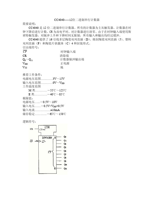
简要说明:
CC4040-----12位二进制串行计数器
CC4040 是 12 位二进制串行计数器。所有的计数器为主从触发器。计数器在时 钟下降沿进行计数。CR 为高电平时,对计数器进行清零。由于在时钟输入端使用斯
密特触发器,对脉冲上升和下降时间无限制,所有输入和输出均经过缓冲。
CC4040 提供了 16 引线多层陶瓷双列直插(D)、熔封陶瓷双列直插(J)、塑料 双列直插(P)和陶瓷片状载体(C)4 种封装形式。 引出端符号:
CP 上升或下降时间
5.0 10.0 20.0
规范值
VDD=5V 最小 最大
-
3.5
140 -
数控刀具命名规则及牌号材质详情

数控刀具型号编号规则——山特维克事例:CNMG120408-PM 4205C:刀片形状,菱形80N:刀片后脚,负角型刀片M:公差G:刀片类型PM:刀片槽形4205:刀片牌号(材质)GC4205(HC)–P05(P01-P15)CVD涂层牌号,具有优良的耐沟槽磨损性与抗塑性变形性。
当在钢的半精加工到粗加工应用中要求高金属去除率时推荐用于稳定的工况。
能承受高温,并且不会降低干湿加工应用中的刃线安全性。
1、2、刀片牌号(车削)用于普通车削的牌号----P钢、铸钢、长切屑可锻铸铁。
基本牌号CT5015(HT)–P10(P01-P20)具有优良的抗积屑瘤与抗塑性变形能力的非涂层金属陶瓷牌号。
新型配方提高了韧性。
用于要求高表面质量与/或低切削力的低合金钢与合金钢的精加工。
fnxap<0、35mm2GC1125(HC)–M25(M10-M30PVD涂层微颗粒硬质合金。
推荐用于中等到低切削速度下各种不锈钢的精加工。
锋利的切削作用与优良的切削刃韧性相结合时,或要求很高的表面质量时,该牌号表现优异。
其很高的耐热冲击性能适用于轻间断切削。
GC1525(HC)-P15(P05-P25)PVD涂层金属陶瓷牌号。
具有优良的耐磨损性与刃口韧性。
用于低碳钢与低合金钢的精加工与半精加工。
适用于中等与高切削速度下要求高表面质量的场合。
fnxap<0、35mm2GC4205(HC)–P05(P01-P15CVD涂层牌号,具有优良的耐沟槽磨损性与抗塑性变形性。
当在钢的半精加工到粗加工应用中要求高金属去除率时推荐用于稳定的工况。
能承受高温,并且不会降低干湿加工应用中的刃线安全性。
GC4215(HC)-P15(P01-P30)用于精加工到粗加工的CVD涂层硬质合金牌号,适合于钢与钢铸件的连续切削至轻型间断切削应用。
梯度基体与耐磨涂层相结合,最佳化了硬度与韧性。
不论湿切削还就是干切削均能承受高温,同时又不会牺牲刃线安全性。
GC4225(HC)-P25(P10-P40CVD涂层硬质合金材质,用于钢与钢铸件的精加工到粗加工。
齿面碟形防松垫圈规格

三、齿面碟形防松垫圈规格
发布时间:2008.04.29 新闻来源: 浏览次数:48
齿面碟簧防松垫圈解决了螺钉连接的安全问题。
其特有的性能是由齿形表面提供的,S系列和VS系列因减少震动提供了最佳的安全性。
光滑地倒圆的齿状表面均匀地压在螺栓连接的接触面上,安全地压紧连接件,不致于损坏,作为连接防松之用。
碟簧产生变形量(H-S)
在螺母上保持一定压力。
齿状表面的内摩擦为防松提供了附加的保护作用。
S系列(标准载荷),VS系列(中等载荷)。
标准的成品:弹簧钢、淬火,表面发黑处理。
还可用不锈钢、磷青钢制造,其他的表面处理方法有镀锌或镀镉。
(sp)与法兰螺母/,使用在大孔或长孔上,以
,例如铝。
标准不锈钢垫圈 大外径不锈钢垫圈(sp)
M64 2 1/2" 67.1 95.0 9.0 24.4 M68 71.1 100.0 9.0 27.2 M72 75.1 105.0 9.0 29.7 M76 3" 79.1 110.0 9.0 32.2 M80 83.1 115.0 9.0 34.8
八、耐温碟形弹簧规格(≤400℃)
发布时间:2010.03.02 新闻来源: 浏览次数:19
六、不锈钢碟形弹簧规格
发布时间:2010.03.02 新闻来源: 浏览次数:30
十一、双槽形碟形弹簧规格
发布时间:2008.04.29 新闻来源: 浏览次数:21。
C4400中文资料
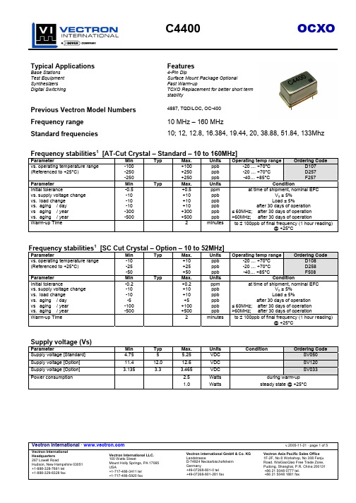
Vectron International · v.2005-11-21 · page 1 of 5Vectron International Vectron international GmbH & Co. KG Vectron Asia Pacific Sales OfficeTypical ApplicationsFeaturesBase Stations 4-Pin Dip Test Equipment Surface Mount Package OptionalSynthesizers Fast Warm-up Digital Switching TCXO Replacement for better short termstabilityPrevious Vectron Model Numbers4887, TQDILOC, OC-400Frequency range10 MHz – 160 MHzStandard frequencies10; 12, 12.8, 16.384, 19.44, 20, 38.88, 51.84, 133MhzFrequency stabilities 1 [AT-Cut Crystal – Standard – 10 to 160MHz]ParameterMin Typ Max. Units Operating temp range Ordering Code vs. operating temperature range -100 +100 ppb -20 … +70°C D107(Referenced to +25°C) -250+250 ppb -20 … +70°C D257-250+250 ppb -40… +85°C F257 Parameter Min Typ Max. Units Condition Initial tolerancevs. supply voltage change vs. load change vs. aging / day vs aging / year vs. aging / year -0.5 -10 -10 -10 -300 -500 +0.5 +10 +10 +10 +300 +500 ppm ppb ppbppbppbppbat time of shipment, nominal EFC V S ± 5%Load ± 5% after 30 days of operation ≤ 60MHz; after 30 days of operation >60MHz; after 30 days of operation Warm-up Time2 minutes to ± 100ppb of final frequency (1 hour reading)@ +25°CFrequency stabilities 1 [SC Cut Crystal – Option – 10 to 52MHz]ParameterMin Typ Max. Units Operating temp range Ordering Code vs. operating temperature range -10 +10 ppb -20 … +70°C D108(Referenced to +25°C) -25+25 ppb -20 … +70°C D258-50+50 ppb -40… +85°C F508 Parameter Min Typ Max. Units Condition Initial tolerancevs. supply voltage change vs. load change vs. aging / day vs aging / year vs. aging / year -0.2 -10 -10 -5 -100 -500 +0.2 +10 +10 +5 +100 +500 ppm ppb ppbppbppbppbat time of shipment, nominal EFC V S ± 5%Load ± 5% after 30 days of operation ≤ 60MHz; after 30 days of operation >60MHz; after 30 days of operation Warm-up Time2 minutes to ± 100ppb of final frequency (1 hour reading)@ +25°CSupply voltage (Vs)ParameterMin Typ Max. Units Condition Ordering CodeSupply voltage [Standard] 4.75 5 5.25 VDC SV050Supply voltage [Option] 11.4 12.0 12.6 VDC SV120 Supply voltage [Option] 3.135 3.3 3.465 VDCSV033Power consumption 2.5 Watts during warm-up1.0Wattssteady state @ +25°CVectron International · v.2005-11-21 · page 2 of 5Vectron International Vectron international GmbH & Co. KG Vectron Asia Pacific Sales Office RF outputParameterMin Typ Max. Units Condition Ordering CodeSignal [Standard] HCMOS RFHLoad 15 pF Signal Level (Vol) 0.5 VDC with Vs=12.0V or 5.0V and 15pF load0.3 VDC with Vs=3.3V and 15pF load Signal Level (Voh) 3.7 VDC with Vs=12.0V or 5.0V and 15pF load2.4 VDC with Vs=3.3V and 15pF load Duty cycle45 55 % @ (Voh-Vol)/2Frequency Tuning (EFC) 10 to 80MHzParameterMin Typ Max. Units Condition Tuning Range ±5.0 ±12ppm with AT cut Crystal Tuning Range ±1.0 ±3ppm with SC cut Crystal Linearity 5 %Tuning SlopePositiveControl Voltage Range 0 2 4 VDC with Vs=12.0V or 5.0VControl Voltage Range0.01.42.8VDCwith Vs=3.3VAdditional parametersParameter Min Typ Max. Units ConditionPhase Noise 3-65 dBc/Hz 1 Hz @ 10 MHz -95 dBc/Hz 10 Hz -120 dBc/Hz 100 Hz -140 dBc/Hz 1 kHz -145 dBc/Hz 10 kHz Weight 8.0 g Processing & Packing Handling & processing noteAbsolute Maximum RatingsParameter Min Typ Max. Units Condition Supply voltage (Vs) 7.0 V with Vs=5.0VDC 28 V with Vs =12VDC 7.0 V with Vs =3.3VDC Output Load 50 pF Operable temperature range -55 +85 °C Storage temperature range -55 +125 °CVectron International · v.2005-11-21 · page 3 of 5Vectron InternationalVectron international GmbH & Co. KG Vectron Asia Pacific Sales OfficeDimensions: mmPin Connections1 Electrical Frequency Adjust Input (EFC) 7 Ground (Case) 8 RF Output14Supply Voltage InputStandard Shipping Method (For Type B Enclosures)AXVectron International · v.2005-11-21 · page 4 of 5 Vectron International Vectron international GmbH & Co. KGVectron Asia Pacific Sales OfficeVectron International · v.2005-11-21 · page 5 of 5Vectron International Vectron international GmbH & Co. KG Vectron Asia Pacific Sales Office How to Order this Product:Step 1Use this worksheet to forward the following information to your factory representative: Model Stability Code Supply Voltage Code RF Output CodePackage CodeFrequencyC4400RFHExample:C4400D207SV050RFHA110.000 MhzStep 2 The factory representative will then respond with a Vectron Model Number in the following configuration: Model Package CodeDash Dash NumberC4400[Customer Specified Package Code]-[Factory Generated 4 digit number]Typical P/N = C4400A1-0001Notes:1 Contact factory for improved stabilities or additional product options. Not all options and codes are available at all frequencies.2 Unless otherwise stated all values are valid after warm-up time and refer to typical conditions for supply voltage, frequency control voltage, load, temperature (25°C)3 Phase noise degrades with increasing output frequency.4 Subject to technical modification.5 Contact factory for availability.。
常用钢材
塑胶模具常用钢材(一)C45W中炭钢美国标准编号:AISI1050~1055;日本标准编号:S50C~S55C德国标准编号:1.1730。
中炭钢或45#钢香港称为王牌钢,此钢材的硬度为:HB170~HB220,价格便宜,加工容易,在模具上用作模架,顶柱,及一些不重要的零件上,市场上一般标准模架是采用此种钢材;(二)40CrMnMo7预硬塑胶模具钢美国、日本、新加坡、香港、中国标准编号:AISIP20,德国及有些欧洲国家编号:DIN:1.2311、1.2378、1.2312。
此种钢是预硬钢,一般不适宜热处理,但是可以氮化处理,此钢种的硬度差距也很大,由280HRC~400视乎那间钢厂的标准,由于已作预硬处理,机械切削也不太困难,所以很合适做一些中下价模具的镶件,有些生产大批量的模具模架也采用此钢材(有些客户指定要用此钢作模架),好处是硬度比中炭钢高,变形也比中炭钢稳定,P20此种钢由于在塑胶模具被广泛采用,所以品牌也很多,其中在华南地区较为普遍的品牌有:ASSAB一胜百牌,瑞典产的有两种不同硬度,718SHB290~HB330(330~340HRC)、718HHB330~HB370(340~380HRC)。
大同钢厂,日本产:NAK80(硬度400HRC+20)及NAK55(硬度400HRC+20)两种,一般情况下,NAK80做定模镶件,NAK55做动模镶件,要留意NAK55不能直接做EDM皮纹,据钢材代理解释是含硫的关系,所以EDM后留有条纹的;德胜钢厂THYSSEN,德国产,有好几种编号:GS-711(硬度340~360HRC)、GS738(硬度320~350HRC)、GS808V AR(硬度380~420HRC)、GS318(硬度290~330HRC)、GS312(硬度290~330HRC),GS312含硫不能做EDM纹,在欧洲做模架较为普遍,GS312的Code为40CrMNMoS8,百禄(BOHLER)奥国产,编号有:M261(380~420HRC)、M238(360~420HRC)、M202(290~330HRC),M202不能做EDM纹,也是含硫,尚有其他品牌,不能尽录。
铜管牌号

CuNi30Mn1Fe
C71630
力学性能良好,耐蚀性好,切削性差,造船业中在高温,高压,高速,条件下工作的冷凝器和恒温器
BFe10-1-1
CuNi10Fe1Mn
C70600
结构白铜,强度,硬度,较BFe30-1-1低,塑性较其高,可代替BFe30-1-1铍青源自管QBe2CuBe2
C17200
C1720
是一种理论化综合性能优良的合金,热处理后具有高的强度,硬度,弹性,耐磨性,耐热性和耐寒性,无磁性,易于焊接,且抗蚀性良好
QBe1.7
CuBe1.7
C17000
C1700
与QBe2性能相近,但在弹性,迟滞性,疲劳强度,弹性稳定性
QBe1.9
硅青铜管
QSi1-3
C3771
是一种广泛应用的铅黄铜,具有良好的力学性能,且切削加工性好,可承受冷热压力加工,使用于切削加工及冲压加工的各种结构零件,如垫片,衬套等
HPb59-3
HPb89-2
HPb66-0.5
HPb62-3
锡黄铜管
HSn70-1
有高的耐腐蚀性,有良好的力学性能,在冷,热态下压力加工性良好,可用于舰船上的耐蚀零件及蒸汽,油类等介质接触的零件及导管
C6301
QAL10-3-1.5
C63200
具有高的强度及耐摩擦性,不易钎焊,有较高抗氧化性和耐蚀性,制作高温条件下的耐磨件和标准件,如齿轮,轴承,飞轮
QAL10-4-4
CuAl10Ni5Fe5
C63300
CA104
具有高强度,高温力学性能两好,良好的减摩性,不易钎焊,抗蚀性良好,制作高强的耐磨零件和高温条件下工件,如轴衬,轴套,法兰盘,齿轮及其他重要耐蚀零件,耐磨零件
塑胶模常用钢材及硬度说明

塑胶模具常用钢材(一) C45 W 中炭钢美国标准编号:AISI 1050 ~ 1055;日本标准编号:S50C ~ S55C德国标准编号:1.1730。
中炭钢或45# 钢香港称为王牌钢,此钢材的硬度为:HB170 ~ HB220,价格便宜,加工容易,在模具上用作模架,顶柱,及一些不重要的零件上,市场上一般标准模架是采用此种钢材; (二)40 CrMn Mo 7 预硬塑胶模具钢美国、日本、新加坡、香港、中国标准编号:AISI P20,德国及有些欧洲国家编号:DIN:1.2311、1.2378、1.2312。
此种钢是预硬钢,一般不适宜热处理,但是可以氮化处理,此钢种的硬度差距也很大,由280HRC ~ 400 视乎那间钢厂的标准,由于已作预硬处理,机械切削也不太困难,所以很合适做一些中下价模具的镶件,有些生产大批量的模具模架也采用此钢材(有些客户指定要用此钢作模架),好处是硬度比中炭钢高,变形也比中炭钢稳定,P20此种钢由于在塑胶模具被广泛采用,所以品牌也很多,其中在华南地区较为普遍的品牌有:ASSAB 一胜百牌,瑞典产的有两种不同硬度,718S HB290~HB330(330~340HRC)、718H HB330~HB370 (340~380HRC)。
大同钢厂,日本产:NAK 80(硬度400HRC+20)及NAK55(硬度400HRC+20)两种,一般情况下,NAK 80做定模镶件,NAK55做动模镶件,要留意NAK55 不能直接做EDM皮纹,据钢材代理解释是含硫的关系,所以EDM后留有条纹的;德胜钢厂THYSSEN ,德国产,有好几种编号:GS-711(硬度340~360HRC)、GS738(硬度320~350HRC)、GS808VAR(硬度380~420HRC)、GS318(硬度290~330HRC)、GS312(硬度290~330HRC),GS312含硫不能做EDM纹,在欧洲做模架较为普遍,GS312的Code 为40 Cr MN Mo S8 ,百禄(BOHLER)奥国产,编号有:M261(380~420HRC)、M238(360~420HRC)、M202(290~330HRC),M202不能做EDM纹,也是含硫,尚有其他品牌,不能尽录。
SC225中文资料

SMT - on ceramic technology Metal case Isolation I/O 500Veff EMI/RFI radiated EN55022-B Short circuit proof 100% burn-in and parameter test Switching frequency: 200kHz
ISO 9001 Registered
Sales office for Germany ELEKTRA REINSTADLER GmbH Arnbacherstr., 32 - 85247 Schwabhausen Germany Tel.: +49 08138 9161 - Fax.: +49 08138 8484 e-mail: elektra.reinstadler@t-online.de
Connections Pin 1 .................................... +Input Pin 2 ..................................... -Input Pin 3 ............................... +Output 1 Pin 4 ................................ -Output 1 Pin 5 ............................... +Output 2 Pin 6 ................................ -Output 2 Pin 7 ..................................... no pin
DC/DC Converter SC225
Endevco Model 2222C Microminiature Accelerometer I
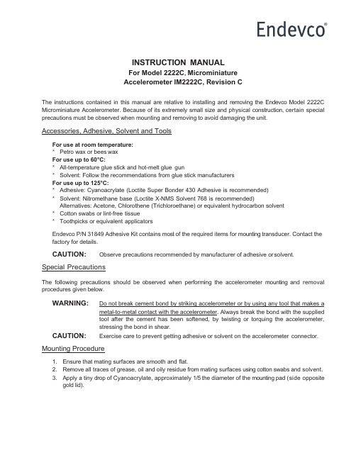
INSTRUCTION MANUALFor Model 2222C, MicrominiatureAccelerometer IM2222C, Revision CThe instructions contained in this manual are relative to installing and removing the Endevco Model 2222C Microminiature Accelerometer. Because of its extremely small size and physical construction, certain special precautions must be observed when mounting and removing to avoid damaging the unit.Accessories, Adhesive, Solvent and ToolsFor use at room temperature:*Petro wax or bees waxFor use up to 60°C:*All-temperature glue stick and hot-melt glue gun*Solvent: Follow the recommendations from glue stick manufacturersFor use up to 125°C:*Adhesive: Cyanoacrylate (Loctite Super Bonder 430 Adhesive is recommended)*Solvent: Nitromethane base (Loctite X-NMS Solvent 768 is recommended)Alternatives: Acetone, Chlorothene (Trichloroethane) or equivalent hydrocarbon solvent *Cotton swabs or lint-free tissue*Toothpicks or equivalent applicatorsEndevco P/N 31849 Adhesive Kit contains most of the required items for mounting transducer. Contact the factory for details.CAUTION:Observe precautions recommended by manufacturer of adhesive or solvent.Special PrecautionsThe following precautions should be observed when performing the accelerometer mounting and removal procedures given below.WARNING: Do not break cement bond by striking accelerometer or by using any tool that makes a metal-to-metal contact with the accelerometer. Always break the bond with the suppliedtool after the cement has been softened, by twisting or torquing the accelerometer,stressing the bond in shear.CAUTION:Exercise care to prevent getting adhesive or solvent on the accelerometer connector. Mounting Procedure1. Ensure that mating surfaces are smooth and flat.2. Remove all traces of grease, oil and oily residue from mating surfaces using cotton swabs and solvent.3. Apply a tiny drop of Cyanoacrylate, approximately 1/5 the diameter of the mounting pad (side oppositegold lid).IM2222C, Page 24. Spread the cement with toothpick to form thin, uniform layer covering area of contact, and immediatelyposition accelerometer on mating surface.5. Press down and hold accelerometer firmly in place for 30 seconds while cement sets. Allow cement toset for at least several minutes for maximum strength.6. If the accelerometer is to operate at low frequencies and/or large acceleration levels, the accelerometercable must be secured to the vibrating structure as close as possible to the accelerometer to avoid cable damage.Removal Procedure1.Apply solvent around accelerometer base (side opposite gold lid) with cotton swab and wait a shortperiod for cement to soften. Repeat the procedure if the solvent evaporates too soon.2.Break cement bond, using removal tool P/N 2943B (supplied with the accelerometer). Always use thistool to remove the Model 2222C Accelerometer from the test structure. Twist or torque the accelerometer, stressing the bond in shear.3.Remove cement residue on the accelerometer using a cotton swab dipped in solvent or equivalentremover. A short soak will facilitate this process. Repeat, if necessary, to remove all traces of adhesive.Ensure that all excess adhesive forming fillet around the accelerometer case or built up on the sides of the accelerometer has been removed.Failure to heed this caution may prevent proper use of removal tool and result in damage to the accelerometer.4.Wipe surfaces clean with cotton swabs or lint-free tissue dipped in solvent.5.NOTE: The accelerometer base must not be filed, sanded, roughened, or edges burred during removalof the cement. A rough mounting surface on an accelerometer can result in poor frequency response and an increase in transverse sensitivity.Replacement of 3093 Cable AssemblyCAUTION: Do not detach cable from accelerometer while the Model 2222C Accelerometer is exposed to a dirty or humid environment. Detachment of cable will expose the sensing element tothe atmosphere, and any conducting or solid particles or moisture entering theaccelerometer will result in deterioration of its operation.Only remove the cable assembly in a clean, dry (<50% RH) atmosphere. Note that the connector has a right-hand thread. Hold the accelerometer between two fingers. Align the flats on the connector with the open end of the wrench (P/N 16205, supplied with the accelerometer). Turn cable connector counter clockwise (CCW) to remove cable assembly.To install cable assembly, dip the small threaded end of the new cable into the capsule of sealing compound (supplied). Again, holding the accelerometer with two fingers on one hand, screw the connector into the case and tighten with the 16205 wrench, using about 1-lb f (~4.5 N) force on the tool. This is approximately a 1 lb f-in (~0.1 Nm) torque. For most people, the accelerometer will become difficult to hold in the fingers for torque values greater than 1 lb f-in.CAUTION: Do not clamp the accelerometer in a vise during attachment of cable. It is recommended that the cable connector be back-threaded before engaging the threads to prevent cross-threading.WARNING:If the lid came off due to mounting mishap, DO NOT try to repair unit in thefield. Special repair procedure and materials are needed to maintain properelectro-magnetic shielding of sensing element. Contact the factory wheneverrepair is required.。
ABB Endura AZ40 Sensor Assembly Heater and Thermoc

—A B B M E A SU R EM ENT & A N A LY TI C S | I NS TRUC TI O N | I NS/A N A I NS T/008-EN R E V. BEndura AZ40Sensor assemblyHeater and thermocouple kitKit reference: AZ400 753Measurement made easy1 IntroductionThis publication details replacement procedures for AZ40 cartridge heaters and thermocouples(AZ400 753) fitted to Endura AZ40 sensor assemblies. Before carrying out any procedures, read Section 3. These procedures must be carried out by a suitably-trained technician.Kit contains:• Heaters (4 x 100 W, 2 x 70 W), 2 x thermocouples • This publicationTools required• Transmitter door key (supplied withtransmitter)• Operating instruction OI/AZ40-EN*• Medium flat-bladed screwdriver• Small flat-bladed screwdriver• Anti-seize compound (suitable fortemperatures up to 200 °C [392 °F])*Operating instruction OI/AZ40-EN contains mandatory safety information and can be downloaded from the link (above) or by scanning this code:2 For more information Further information is available from:/analyticalor by scanning these codes:Sales ServiceEndura AZ40 sensor assembly2INS/ANAINST/008-EN Rev.B |Endura AZ40|Sensor assembly |Heater and thermocouple kit3 Health & Safety3.1 Safety precautionsBe sure to read, understand and follow the instructionscontained within this document before and during use of the equipment. Failure to do so could result in bodily harm or damage to the equipment.3.2 Potential safety hazards3.2.1 Process conditions and requirements3.2.2 Endura AZ40 sensor – fibrous material in probe assembly3.2.3 Endura AZ40 sensor / probe – installation to pressurized processWARNING – Bodily injury Installation, operation, maintenance and servicing must be performed:—by suitably trained personnel only—in accordance with the information provided inthis document—in accordance with relevant local regulationsWARNING – Bodily injury Environmental conditions—High air / equipment / structure temperatures, poorair quality and adverse environmental conditions may be present when the process is running.—It is recommended that the process is shut downbefore performing these procedures.—The process must be cool enough to enableshutdown, disconnection and removal of the sensor in a safe manner and in accordance with relevant local regulations.—Appropriate PPE, including mask and goggles mustbe worn when preparing the process for theseprocedures.WARNING – Serious damage to health Fibrous material—The sensor and probe assemblies (standard andhigh temperature versions) contain fibrous material that can be a health hazard if airborne.—The material, predominantly – aluminosilicaterefractory fibres, CAS 142844-00-6. Refractory ceramic fibres (RCF) are classified as:–Category 1B carcinogen under regulation (EC) No 1272/2008 – the classification, labelling and packaging regulations.–Category 2B carcinogen by inhalation by The International Agency for Research on Cancer (IARC).—When removing the sensor cover and subsequentmaintenance activities, exposure to the airborne fibres could occur. ABB have conducted airsampling assessments within the breathing zone of the operator and have identified that an exposure limit of 1 fibre / cubic centimetre is unlikely to occur.—Exposure to any carcinogen must be kept as low asreasonably practicable.—Appropriate PPE defined below, must beworn when working with probe assemblies (all installation, replacement, maintenance procedures):– A face fit tested, half mask conforming to EN140 (or equivalent) with a level 3 particulate filter conforming to EN 143 (or equivalent).–Disposable protective coveralls in accordance with Type 5 ISO 13982-1:2004 (or equivalent).–Goggles and gloves.DANGER – Serious damage to health / risk to life Pressurized equipment – do not install / remove / the sensor / probe if the process is at positive pressureInstallation, operation, maintenance and servicing of pressurized equipment must be performed:—by suitably trained personnel only—in accordance with the information provided in thisdocument—in accordance with relevant local regulations —when process conditions are suitable to allowenough to enable installation / maintenanceEndura AZ40|Sensor assembly |Heater and thermocouple kit |INS/ANAINST/008-EN Rev.B 33.2.4 Endura AZ40 sensor – high operational temperature on exposed parts3.2.5 Endura AZ40 sensor – weight3.2.6 Endura AZ40 analyzer – electricalEndura AZ40 transmitter – weightWARNING – Bodily injuryHigh temperature on exposed surfaces – see Fig. 3.1—During operation, exposed sensor surfaces canreach 200 °C (392 °F).—Ensure suitable PPE is available and is worn beforehandling the sensor.—Do not touch exposed surfaces until the sensor /probe is cool enough to handle with PPE.Fig. 3.1 High temperature points on exposed sensor surfaces during operationWARNING – Bodily injury–The sensor weighs 9.0 kg (20 lb). When fitted with a probe / filter assembly, the combined sensor / probe weight is dependent on probe length / type plus filter option – refer to Operating instruction OI/AZ40-EN for weight details.–The sensor / probe assembly must be mounted in accordance with the information supplied in Operating instruction OI/AZ40-EN.—Suitable lifting equipment must be available wheninstalling / removing the sensor / probe from theprocess.WARNING – Bodily injuryTo ensure safe use when operating this equipment, the following points must be observed:—up to 240 V AC may be present. Ensure the supplyis isolated before removing the terminal cover—normal safety precautions must be taken to avoidthe possibility of an accident occurring when operating in conditions of high pressure and / or temperatureSafety advice concerning the use of the equipment described in this document or any relevant Material Safety Data Sheets (where applicable) can be obtained from the Company, together with servicing and spares information.WARNING – Bodily injury–The transmitter weighs 7.6 kg (17 lb) and must be mounted in accordance with the information supplied in Operating instruction OI/AZ40-EN.—Suitable lifting equipment must be available wheninstalling / removing the transmitter from themounting.4INS/ANAINST/008-EN Rev.B |Endura AZ40|Sensor assembly |Heater and thermocouple kit4 Isolating the transmitterReferring to Fig. 4.1.1.Isolate transmitter A from incoming mains powerssupplies B .DANGER – Serious damage to health / risk to life The transmitter must be isolated from mains power supplies before performing this procedure.Fig. 4.1Isolating the transmitter from incoming mains power suppliesEndura AZ40|Sensor assembly |Heater and thermocouple kit |INS/ANAINST/008-EN Rev.B55 Shutting down / removing the sensor assembly from the process5.1 Shutting the sensor assembly down at the process Referring to Fig. 5.1.1.Close the air supply valve A and shut down the test gasline B at the supply.5.2 Disconnecting the sensor air and test gas supplies at the processReferring to Fig. 5.2:1.Disconnect air line B and test gas line C at sensor D .5.3 Disconnecting the sensor electrical power and signal cables at the processReferring to Fig. 5.3:e a medium flat-bladed screwdriver to unscrew 4(captive) cover screws A and remove cover B from sensor assembly C .2.Disconnect mains cable D from terminal block E3.Disconnect signal cable F from terminal block G .4.Disconnect thermocouple cables H from terminal blockI .5.If optional blowback is fitted, disconnect cable J fromterminal block K .DANGER – Serious damage to health / risk to life Allow sufficient time for the sensor assembly to cool before performing these procedures.Fig. 5.1 Shutting down instrument air and test gas suppliesFig. 5.2Disconnecting instrument air and test gas suppliesDANGER – Serious damage to health / risk to life Allow sufficient time for the sensor assembly to cool before performing this procedure.DANGER – Serious damage to health / risk to life The transmitter must be isolated from mains power supplies before performing this procedure.Fig. 5.3Disconnecting sensor cablesl o w b a c kl o w b a c kn l e t T /C n l e t T /C c r e e nu t l e t T /u t l e t T /a r t h6INS/ANAINST/008-EN Rev.B |Endura AZ40|Sensor assembly |Heater and thermocouple kit5.4 Removing the sensor assembly from the processReferring to Fig. 5.4:e a 10 in. adjustable spanner (wrench) to remove 4 nuts,washers and lockwashers A securing sensor assembly B to mounting flange C . Set items aside for re-use.2.Carefully remove the sensor assembly and the attachedprobe (including filter assembly) from the process.3.Temporarily cover process opening until the sensorassembly is ready to be re-installed.DANGER – Serious damage to health / risk to life Allow sufficient time for the sensor assembly to cool before performing this procedure.Fig. 5.4Removing the sensor assembly from the processEndura AZ40|Sensor assembly |Heater and thermocouple kit |INS/ANAINST/008-EN Rev.B 76 Heater and thermocouple locations on sensor flange block and CO heater blockRefer to Fig. 6.1 for cartridge heater and thermocouple locations on the sensor flange block and CO heater block:Fig. 6.1 Heater and thermocouple locations on sensor flange blockand CO heater blockKey:A Flange block cartridge heaters: 100 W – Section 8.1, page 9B CO heater block cartridge heaters: 70 W – Section 8.2, page 10C CO heater block thermocouple: T/C 1 – see Section 8.3, page 11D Flange block thermocouple: T/C 2 – see Section 8.4, page 14HTR4Sensor shown with top cover removed7 Removing / Refitting sensor covers7.1 Removing sensor coversReferring to Fig. 7.1:1.Unscrew 4 (captive) cover retaining screws A using amedium flat-bladed screwdriver. and remove sensor cover B.2.Unscrew 2 (captive) cover retaining screws C using amedium flat-bladed screwdriver and remove sensorterminal cover D.Retain covers B and D for re-use.7.2 Refitting sensor coversReferring to Fig. 7.1:1.Apply a light coating of anti-seize compound (suitablefor temperatures up to 200 °C [392 °F]) to the threadsof sensor cover mounting screws A and C.2.Refit the sensor cover B and sensor terminal cover D inthe reverse order of removal – refer to Section 7.1.3.Prepare the sensor assembly for operation by reversingthe procedures in Sections 5 and 4 (pages 5 and 4).4.Refer to Operating instruction OI/AZ40-EN to restore theanalyzer to full operational condition.IMPORTANT (NOTE)Check the seals fitted to each cover. If they need replacing or seals have bonded to the mating surfaces of the sensor assembly, replace them – see Instruction INS/ANAINST/10-EN.Fig. 7.1Removing sensor covers8INS/ANAINST/008-EN Rev.B|Endura AZ40|Sensor assembly|Heater and thermocouple kit2.3.4.5.6.7.8.9.Fig. 8.1 Replacing flange block cartridge heaters (100 W)Endura AZ40|Sensor assembly|Heater and thermocouple kit|INS/ANAINST/008-EN Rev.B98.2 CO heater block cartridge heaters (70 W)1.2.3.4.5.heater block H. If CO cartridge heaters are stuck, rotate them or use a suitably sized rod to push them out from the other side.6.Slider each new CO heater block cartridge heater into theCO heater block H.7.Take one wire from each new CO heater block cartridgeheater and twist both wires together to form a twisted pair.8.Apply a small amount of anti-seize compound (suitable fortemperatures up to 200 °C [392 °F]) to the thread of screwF and secure large washerG to retain the CO heaterblock cartridge heaters in CO heater block H.9.Feed the 3 x CO heater block cartridge heater wires downthrough left opening B in the flange block and make top terminal block connections at connectors A as follows:—connect the twisted pair to terminal 6.—connect the free wire from cartridge heater D (HTR1) to terminal 4.—connect the free wire from cartridge heater E (HTR2) to terminal 5.10.To replace CO heater block thermocouple (T/C 1), refer toSection 8.3, page 11. To refit sensor covers refer to Section 7.2, page 8.11.Refit sensor covers – refer to Section 7.2, page 8.Fig. 8.2 Replacing CO heater block cartridge heaters (70 W)CF GHE10INS/ANAINST/008-EN Rev.B|Endura AZ40|Sensor assembly|Heater and thermocouple kitEndura AZ40|Sensor assembly |Heater and thermocouple kit |INS/ANAINST/008-EN Rev.B 118.3 CO heater block thermocouple (T/C 1)Referring to Fig. 8.3:1.Place the sensor assembly on a clean flat surface with theflange studs pointing down.e a small flat-bladed screwdriver to depress the springconnectors at terminal numbers 8, 9 and 10 anddisconnect CO heater block thermocouple T/C 1 wires from top terminal block connectors A .3.Unscrew O 2 sensor A from manifold block B using a7/8 in. spanner (wrench) and withdraw the sensor.CAUTION – Minor injuriesThe O 2 sensor must be removed to enable access to COe heater block thermocouple T/C 1 (steps 1 to 3).CAUTION – Minor injuriesDo not overtighten when refitting the O 2sensor.Fig. 8.3 Removing the O 2 sensor8O2 HTR WHT+10O2 SEN BLK9O2 HTR WHT–Referring to Fig. 8.4:e a small flat-bladed screwdriver to depress the springconnectors at terminal numbers 17 and 19 and disconnect CO heater block thermocouple T/C 1 wires from topterminal block connectors A.5.Pull thermocouple (T/C 1) wires up through (right) openingB in flange block C.6.Carefully slide CO heater block insulation D away fromflange block C.e a small flat-headed screwdriver to remove screw Ewith attached thermocouple retaining washer F from CO heater block G. Retain screw / washer assembly forre-use.8.Withdraw thermocouple (T/C1) H from CO heater blockG and discard thermocouple.9.Slide the new thermocouple (T/C1) into its chamber in COheater block G.10.Apply a small amount of anti-seize compound (suitable fortemperatures up to 200 °C [392 °F]) to the thread of screwE and use a small flat-headed screwdriver to securescrew E with attached thermocouple retaining washerF to CO heater block G.11.Feed thermocouple (T/C1) wires down through rightopening B in flange block C and make terminal block connections at the top connectors A as follows:—connect one wire from thermocouple H (T/C1) to terminal 18.—connect one wire from thermocouple H (T/C1) to terminal 19.12.Refit the O2 sensor in the reverse order of removal – referto steps 1 to 3 page 11.13.To replace flange block thermocouple (T/C 2), refer toSection 8.4, page 14.14.Refit sensor covers – refer to Section 7.2, page 8.CAUTION – Minor injuriesAppropriate PPE (gloves / goggles) must be wornwhen performing this step. The heater blockinsulation material is fragile and becomes brittleafter continuous operation. When sliding insulationaway from the manifold, handle with care.12INS/ANAINST/008-EN Rev.B|Endura AZ40|Sensor assembly|Heater and thermocouple kitF EGDFig. 8.4 Replacing CO heater block thermocouple (T/C 1)Endura AZ40|Sensor assembly|Heater and thermocouple kit|INS/ANAINST/008-EN Rev.B138.4 Flange block thermocouple – T/C 2Referring to Fig. 8.5:e a small flat-bladed screwdriver to depress the springconnectors at terminal numbers 16 and 18 and disconnect flange block thermocouple T/C 2 wires from top terminal block connectors A.2.Pull thermocouple (T/C2) wires up through (right) openingB in flange block C.e a small flat-headed screwdriver to unscrew cartridgeheater / thermocouple retainer screw D and removecartridge heater / thermocouple retainer E. Retain items for re-use.Do not disturb cartridge heater F.4.Withdraw thermocouple G (T/C 2) from flange block Cand discard the thermocouple.5.Slide the new thermocouple (T/C 2) into its chamber inflange block C.6.Carefully form the thermocouple through 90 ° so it fits intothe groove in retainer E.7.Apply a small amount of anti-seize compound (suitable fortemperatures up to 200 °C [392 °F]) to the thread ofcartridge heater / thermocouple retainer screw D and usea small flat-headed screwdriver to secure cartridge heater/ thermocouple retainer E to flange block C.8.Feed both thermocouple (T/C2) wires down through rightopening B in flange block C and make terminal block connections at the top connectors A as follows:—connect one wire from thermocouple T/C2 toterminal 16.—connect one wire from thermocouple T/C2 toterminal 18.9.Refit sensor covers – refer to Section 7.2, page 8.IMPORTANT (NOTE)The retainer (E) at this position has a notch usedto guide / restrain the thermocouple. Only use theretainerfrom this position when fitting / replacingthermocouple T/C 2.14INS/ANAINST/008-EN Rev.B|Endura AZ40|Sensor assembly|Heater and thermocouple kitEndura AZ40|Sensor assembly |Heater and thermocouple kit |INS/ANAINST/008-EN Rev.B 15Fig. 8.5Replacing flange block thermocouple (T/C 2)D EFI N S /A N A I N S T /008-E N R e v . B 12.2018—We reserve the right to make technical changes or modify the contents of this document without prior notice. With regard to purchase orders, the agreed particulars shall prevail. ABB does not accept any responsibility whatsoever for potential errors or possible lack of information in this document.We reserve all rights in this document and in the subject matter and illustrations contained therein. Any reproduction, disclosure to third parties or utilization of its contents – in whole or in parts – is forbidden without prior written consent of ABB. © ABB 2018 3KXA722436R2001—ABB Limited Measurement & Analytics Howard Road, St. Neots Cambridgeshire, PE19 8EU UKTel: +44(0************Fax: +44 (0)1480 213 339Email:**********************.comABB Inc.Measurement & Analytics 125 E. County Line Road Warminster PA 18974USATel: +1 215 674 6000Fax: +1 215 674 7183/measurement。
- 1、下载文档前请自行甄别文档内容的完整性,平台不提供额外的编辑、内容补充、找答案等附加服务。
- 2、"仅部分预览"的文档,不可在线预览部分如存在完整性等问题,可反馈申请退款(可完整预览的文档不适用该条件!)。
- 3、如文档侵犯您的权益,请联系客服反馈,我们会尽快为您处理(人工客服工作时间:9:00-18:30)。
NZZV ]]] QORRZKYZ IT▲ Ҳ ԟ ԇExam : C4040-225Title :Version : V9.02Power Systems with POWER7 and AIX & Linux Technical Sales Skills - v21.Which of the following customer environments would benefit most from the implementation of Active Memory Expansion?A.Workloads that peak at different timesB.Workloads with highly compressible in-memory dataC.Workloads that dedicate a large amount of memory to the file cacheD.Workloads with applications configured to pin most of their virtual memoryAnswer: B2.A customer plans to consolidate workloads, but wants the flexibility to move from virtual to physical I/O in the future if their LPAR workload changes.What feature provides this capability?A.NPIVB.DLPARC.Live Partition MobilityD.Shared Ethernet AdapterAnswer: B3.AIX Profile Manager is a tool used for managing which of the following?A.WPAR profileser activity profilesC.Partition profiles on the HMCD.Runtime configuration profilesAnswer: D4.An LPAR has three virtual processors allocated.What is the maximum quantity of physical processors that could be consumed by this LPAR?A.0.3B.3C.12D.30Answer: B5.Which AIX performance tool provides a detailed snapshot of how virtual memory is used?A.tprofB.traceC.vmstatD.svmonAnswer: D6.A customer plans to purchase a new Power 770 server.The customer needs to support WPARs, application mobility, and manage compliance policies.A.AIX Enterprise EditionB.PowerSCAIX Enterprise EditionC.WPAR ManagerAIX Standard EditionD.PowerSCWPAR ManagerAIX Standard EditionAnswer: A7.Which of the following describes how Active Memory Sharing works?A.Automatically disables bad memory DIMMsB.Moves a running workload between different LPARs by copying contents of memorypresses memory so the LPAR thinks it has more than actual physical memory assigned to itD.Virtualizes memory in a shared memory pool; hypervisor automatically moves physical memory between LPARsAnswer: D8.A client is considering implementing Role Based Access Control.What benefit does this bring to the AIX environment?A.It allows for the classification of users and data at different levels.B.It allows for the transfer of encrypted data over the internal network.C.It addresses the issue of system programs with setuid bits turned on.D.It addresses the issue of too many system administrators with root access.Answer: D9.A customer requires a remote Disaster Recovery solution with manual failover and at lowest cost.Which of the following should be suggested?A.MetroMirrorB.PowerHA Enterprise EditionC.General Parallel File System (GPFS)D.Geographic Logical Volume Manager (GLVM)Answer: D10.A customer wants to save on licensing costs for their database servers, which currently run on non-virtualized pSeries servers.A.Elastic CoDB.Full capacity licensingC.Shared processor poolsD.Active Memory ExpansionAnswer: C11.A customer plans to purchase 4 new Power 770 servers and will create up to 50 AIX LPARs.In order to be able to implement AMS and LPM.Which PowerVM Edition will the customer need?A.Basic EditionB.Express EditionC.Standard EditionD.Enterprise EditionAnswer: D12.A customer plans to move an application from their mainframe to a UNIX environment.What primary advantage does AIX have over the competition in preventing inadvertent memory overlays in both thekernel and the application space?A.AltiVecB.Active Memory SharingC.Storage Protection KeysD.Active Memory ExpansionAnswer: C13.What distinguishes micro-partitions from dedicated-processor partitions?A.Virtual I/OB.Virtual processorsC.Dedicated memoryD.Dynamic LPAR capabilityAnswer: B14.A customer has multiple small workloads and is considering both LPAR and WPAR.Which of the following is an advantage of WPAR when compared to LPAR?A.IsolationB.LicensingC.AvailabilityD.AdministrationAnswer: D15.Which of the following permits scheduled collection of memory and processor utilization data for a managed system?A.Active System Optimizer (ASO)B.Dynamic Platform Optimizer (DPO)C.Hardware Management Console (HMC)D.System Management Interface Tool (SMIT)Answer: Cparing AIX and Linux, in which of the following situations should Linux on Power be suggested?A.Requirement for Virtual TapeB.Open source community supportC.Active Memory Sharing is requiredD.PowerVM Lx86 is being implementedAnswer: B17.A client plans to implement a High Availability solution for their existing Power Systems environment.The client was drawn to PowerHA 7.1 due to its integration with Cluster Aware AIX (CAA).A.Cluster Repository diskB.All I/O must be virtualizedC.Smart Assists for PowerHAD.Dependent Resource GroupsAnswer: A18.Which IBM tool is recommended to assist with the design and deployment of partitions?A.eConfiguratorB.Workload EstimatorC.Systems Director ManagerD.System Planning Tool (SPT)Answer: D19.Which statement describes the function of the GPFS Policy Engine?A.It provides a network block abstraction for file system I/OB.It provides asynchronous caching of files on remote clustersC.It enables monitoring of events associated with a filesystem or individual fileD.It manages where file data is placed when created and moved between storage poolsAnswer: D20.A customer plans to purchase 2 new Power 720 servers.The customer is interested in implementing shared processor pools and shared storage pools.Which is the minimum PowerVM Edition that will support this customer's needs?A.Basic EditionB.Express EditionC.Standard EditionD.Enterprise EditionAnswer: C21.A customer is deciding between NPIV and vSCSI for storage virtualization.What must be considered when using vSCSI, but not when using NPIV?A.The requirement for 8Gbps HBAsB.Whether or not to use VIOS storage poolsC.The maximum of 32,000 virtual client devicesD.Multi-path driver licensing for the client partitionsAnswer: B22.AIX and PowerHA licenses can be transferred from one machine to another when both source and destination machines have which characteristic?A.The same model numberB.The same processor groupC.The same customer numberD.The same enterprise numberAnswer: D23.To improve an OLAP application response times a customer requires a SAN-attached SSD storage solution with microsecond latency and highest density per rack.Which of the following supports these requirements?A.EXP30B.Storwize V7000C.Storwize V3700D.FlashSystem 720Answer: D24.A Power Systems customer wants to remove software based replication from their environment and replicate data between DS8000 systems at two sites 350km apart.What is necessary to support this requirement?A.FlashCopyB.MetroMirrorC.GlobalMirrorD.SystemMirrorAnswer: C25.A customer plans to purchase 2 Power 740 servers, and run 10 Red Hat Linux partitions on each server.How many Red Hat licenses are required?A.2B.4C.10D.20Answer: A26.What AIX command permits a user to quickly identify which processes are consuming the most processor resources?A.sarB.tprofC.topasD.svmonAnswer: C27.A prospective customer is interested in running critical Linux workloads.Why should the customer choose Linux on Power versus Linux on a competitive x86 solution?A.More ISV applicationsB.Virtual machine mobilityC.Support for major Linux distributionsD.Reliability, Availability & ServiceabilityAnswer: D28.A customer has a Power 560 and wants to move to a POWER7+ 770.Which of the following is supported?A.Migration to a new system, changing serial numberB.Direct upgrade to Power 770, keeping serial numberC.Upgrade with RPQ to maintain current serial numberD.Two-step upgrade: first to Power 570, then to Power 770, keeping serial numberAnswer: A29.A customer owns two EMC Symmetrix storage units.They are adding 4 new Power 770 servers to their environment.The customer also wants to virtualize their existing storage and add 5TB of Solid State Drives to increase performance for existing AIX and Linux LPARs.A.DS8870B.DCS3700C.Storwize V7000D.San Volume ControllerAnswer: C30.A customer wants to implement a DB2 pureScale HPC cluster on Power Systems with AIX, and is examining the options for the communication adapters in the servers.In addition to InfiniBand, which of the following adapter types is supported?A.Quad Data Rate (QDR)B.Double Data Rate (DDR)C.Fibre Channel Over Ethernet (FCoE)D.Remote Direct Memory Access Over Converged Ethernet (RoCE)Answer: D31.The distribution of entitled capacity among virtual processors in a micro-partition depends on which of the following?A.The processor compatibility modeB.The number of active virtual processors in the partitionC.The number of maximum virtual processors in the partition profileD.The sum of the processor entitlements in the shared processor poolAnswer: B32.How do storage keys in AIX contribute to system reliability and availability?A.They are used to provide active memory mirroringB.They are used to provide active memory expansionC.They are used to prevent application memory access from an unauthorized userD.They are used to protect memory from being accidentally overwritten by another applicationAnswer: D33.A customer is considering upgrading the SEA in the VIO Server (VIOS) from a 1Gb adapter to a 10Gb adapter.Which of the following is unaffected by the upgrade?A.Switch portswork cablesC.VIOS processor allocationD.Client virtual adapter definitionsAnswer: D34.During a solution design discussion with a client, a reference guide featuring side by side comparisonson Power Systems is needed for information and specifications.A.Power Systems Design GuideB.Facts and Features GuideC.System Planning Tool (SPT)D.Systems Performance ReportAnswer: B35.A client would like to manage and monitor a group of servers as a system pool.Which VMControl Edition is required?A.BasicB.ExpressC.StandardD.EnterpriseAnswer: D36.Which of the following is an advantage of system WPARs over application WPARs?er and group isolationB.Support for WPAR mobilityC.Security isolation provided by the HypervisorD.File systems inherited by the global environmentAnswer: A37.A customer has EMC storage and wants to virtualize all SAN disks, including SAN boot disks, to 20 client LPARs of a Power 770.A.NPIV for all clientsB.vSCSI for 20 client LPARsC.vSCSI for 20 clients plus NPIV for 1 clientD.vSCSI for 19 clients and NPIV for 1 clientAnswer: C38.A customer wants to improve their network bandwidth.What is one method they could use?A.VLANB.Link AggregationC.Host Ethernet AdapterD.Shared Ethernet AdapterAnswer: B39.IBM releases updates for the AIX operating system annually.These updates include support for new hardware, software services, and software features.A.Service PackB.Technology LevelC.Maintenance LevelD.HIPER Service PackAnswer: B40.AIX, Linux, and IBM i utilize a type of Capacity on Demand licensing consideration which provides a unit of measure used to differentiate licensing of IBM software on distributed processor technologies.A.Per user licensing (PuL)B.Processor Value Unit (PVU)C.Processor License Unit (PLU)D.Software Tier Licensing (STL)Answer: B41.A customer is performing a daily backup of a large amount of data to a shared SAN tapelibrary.Reducing the overall backup time is a major concern.A.Analysis of throughput bottlenecksB.Addition of Fibre Channel adaptersC.Addition of tape drives on the tape libraryD.Review of processor and memory capacityAnswer: A。