SONIX
sonix基础技术

探头 接收波束形成器
Input
Analog Processing
发射
Accuracy & Reliability
Digital Domain
Digital
010011010111
Processing
Distortio
Sampling Binary Code
Output
Analog Domain
Input
• 传播速度:超声在水中的传播速度-1530米/秒 超声在空气中传播速度-344米/秒( 20°C )
4. 超声波诊断的优点
三棱镜
• 安全、无辐射。适用于胎儿诊断。
• 设备可移动,成本低。
折射
• 实时成像
镜子
• 通过扫描角度变化,获得更佳的图像。
• 多普勒-检测液体流量信息。
反射
超声原理
1. 基本原理:
2005年6月投放市场
Sonix SP (图像增强型)
•洁净处理算法的超声图像 •实时空间合成技术(超声CT) •宽景成像技术 •组织谐波技术 •3D和4D容积图像
2005年5月投放市场
Sonix OP (专业应用型)
•洁净处理算法的超声图像
•多频选择
•M型图像
先进的图像软件包提供:
•彩色、能量、方向多普勒
M型(Time-motion mode)
A模式延时间轴的展开就是M型
彩色从哪儿来???
多普勒效应(Doppler)
超声波在探测移动目标时,其回声的频率会发生变化。利 用多普勒效应可检测血管内有无血流、血流的方向和血流速度。
正频移
负频移
频谱多普勒(Spectral Doppler)
SONIX 8位单片机 SN8P2711A 用户说明书
2.1.1.1 复位向量(0000H)........................................................................................................................................... 10
2.1.3 数据存储器(RAM) ................................................................................................................................................... 16
1.1
功能特性............................................................................................................................................................................. 6
目 录................................................................................................................................................................................................ 3
2.1.1.2 中断向量(0008H)........................................................................................................................................... 11
sonix方案
sonix方案Sonix公司是一家创新的科技企业,致力于开发先进的音频处理解决方案。
Sonix方案是该公司的一项重要产品,下面将对Sonix方案进行详细介绍。
一、概述Sonix方案是一种基于人工智能技术的语音识别和语音转换方案。
该方案通过将声音信号转化为数字数据,并利用先进的算法进行分析和处理,实现自动语音识别、语音转写和语音合成等功能。
Sonix方案具有高度的准确性和响应速度,可广泛应用于语音识别、智能音箱、语音助手、语音控制等领域。
二、核心技术1. 声音信号采集和转换技术:Sonix方案采用先进的数字声音处理技术,能够通过麦克风采集到高质量的声音信号,并将其转化为数字数据,为后续的语音分析和处理提供可靠的数据基础。
2. 语音识别技术:Sonix方案基于深度学习和模式识别技术,具备出色的语音识别能力。
无论是普通话、英语,还是其他语种,Sonix方案都能够准确地将语音信号转换为对应的文字。
3. 语音转写技术:Sonix方案能够将录音文件转写为文本形式,方便用户快速获取录音内容。
同时,Sonix方案还支持多人会议录音的语音转写,为会议记录和整理提供了便利。
4. 语音合成技术:Sonix方案利用自然语言生成技术,将文字数据转化为自然流畅的语音输出。
通过调整声音的音调、速度和音量等参数,Sonix方案能够产生逼真的人声合成效果。
三、应用领域Sonix方案在众多领域中有着广泛的应用,包括但不限于:1. 语音助手:Sonix方案可以与智能音箱、手机等设备相结合,为用户提供智能化的语音交互服务,实现语音控制、智能问答和音乐播放等功能。
2. 语音识别软件:Sonix方案可用于开发语音识别软件,实现文字转写、语音指令和语音搜索等功能,提高用户的工作效率和生活便利性。
3. 语音翻译:Sonix方案可以将语音翻译为不同语种的文本,为跨语言交流提供便捷的工具。
4. 语音教育:Sonix方案可用于开发语音教育应用,帮助学生提高语言学习的效果,实现语音评测和发音纠正等功能。
高级功能(Sonix彩超)简明操作手册

高级功能简明操作手册----Sonxi系列彩超目录一. 适用范围 (1)二 高级功能 (1)1 连续多普勒的操作 (1)2 标准的3D/4D (2)3 空间复合成像 (5)4 全景成像的操作 (6)5 弹性成像及应变比参数测量 (8)6 心脏高级功能--组织多普勒、解剖M型、彩色M型 (11)7 IMT功能使用 (15)8 高级4D成像 (17)9 卵泡自动测量(待验证) (22)10 ECG操作指引 (25)一. 适用范围加拿大优胜医疗有限公司(Ultrasonix Medical Corporation )Sonix系列彩超二. 高级功能1 连续多普勒的操作在B模式下:1、点击操控台的CW键,调节与触控屏上取样门大小相对应的旋钮,以及调节轨迹球调节取样线的角度,2、然后点击更新键,启动CW模式(如下图所示)2.标准的3D/4D1 确保4D探头处于激活状态2.按操控台上的3D/4D按钮,将探头置于扫查区域上方,2 将探头位于感兴趣的上方,使用轨迹球与选择键确定ROI的位置与ROI的大小(详见图1)。
3.点击“选择”按钮后,通过滚动“轨迹球”确定ROI(感兴趣区)的位置以及调整ROI(感兴趣区)的尺寸后,再次点击“选择”按钮,(如下图所示)4.点击触控屏上的3D 或 4D 图标操作按钮,可对应进入3D 模式或4D 模式(详见下图)。
5.按控制台上的更新按键开始采集(如下图所示)。
6.在感兴趣区慢慢移动探头,7.按冻结 键完成采集(如下图所示)8. 采集的3D/4D 图像将显示在显示屏上(如下图所示)。
9. 按重新进行ROI 的设置,重复步骤2到步骤8进行检查10.点击触控屏上的退出图标,则退出3D/4D模式(如下图所示)3 空间复合成像直接在二维模式下点击操作台上的空间复合按钮进入空间复合成像扫描。
下图红色圈的位置。
4 全景成像的操作1 在B 模式下,点击触控屏的Pano (全景成像)按键(如下图所示),显示屏上会显示“Loading Panaramic Tables….(正在加载全景成表…..)”进度条2 使用轨迹球确定Pano (全景)ROI (目标区域)框的纵向位置,点击选择键选择按键可调节区域的大小。
加拿大优胜sonix 01
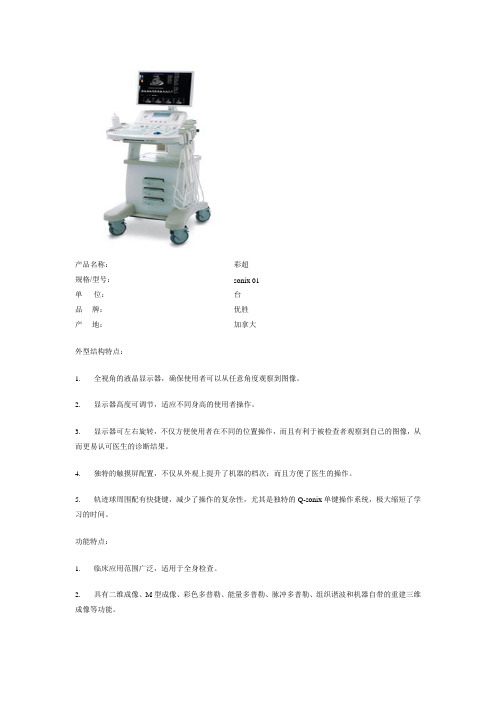
产品名称:彩超
规格/型号:sonix 01
单位:台
品牌:优胜
产地:加拿大
外型结构特点:
1. 全视角的液晶显示器,确保使用者可以从任意角度观察到图像。
2. 显示器高度可调节,适应不同身高的使用者操作。
3. 显示器可左右旋转,不仅方便使用者在不同的位置操作,而且有利于被检查者观察到自己的图像,从而更易认可医生的诊断结果。
4. 独特的触摸屏配置,不仅从外观上提升了机器的档次;而且方便了医生的操作。
5. 轨迹球周围配有快捷键,减少了操作的复杂性,尤其是独特的Q-sonix单键操作系统,极大缩短了学习的时间。
功能特点:
1. 临床应用范围广泛,适用于全身检查。
2. 具有二维成像、M型成像、彩色多普勒、能量多普勒、脉冲多普勒、组织谐波和机器自带的重建三维成像等功能。
3. 凸阵探头的频率范围2—5MHz,具备拓宽扇形成像功能,更大范围的观察脏器。
4. 线阵探头的频率范围5—14MHz,这种宽频带在目前市面上是很少的,并且探头具备梯形成像功能,方便观察更大的诊断范围。
5. 具有2个USB接口,内置CD/DVD刻录机,极大地方便医生保存资料。
6. 背光键键盘和人体工程学设计,使得在光线暗处操作同样方便。
7. 长达4分钟的电影回放
8. 实时网上对话,支持远程会诊。
9. 每年3次的软件升级,确保机器功能的先进性。
SonixTM 2Mx矩阵单元概述说明书

Sonix TM2MxOverviewThe Sonix TM 2Mx matrix unit provides an integral backbone for the base structure of the Sonix TM PA/GA system, housed within an ergonomic and compact 1U chassis. Connectivity of this unit is via colour coded, rapid fi t RJ45 receptacles, to ensure simple installation and ease of servicing. Highly visible front panel status is provided with system activity and status along with external GUI status for remote users.Features•Highly con gurable, hybrid network with bre-optic compatibility• Compact ef cient 1U design • Up to 12 address zones (expandable up to 30 on request)•Control of up to 32 (350w) ampli ers per system (expandable on request)•Interface with up to 24 fully monitored safe & Ex area Hmi access panels•Internally monitored, self-healing RJ45 data networks • Rapid t RJ45 connectivity • For speedy construction and maintenance• PABX connectivity via 2 wire, 2 wire E&M or SIP interface •Duplicate system real time synchronisation with auto switch over• Con gurable via Sonix TM Software • Enhanced distribution of inputs to second 2Mx systems (A+B Plus) • Comprehensive alarm tone library (expandable on request)•Zoned alarms available on requestPA/GA control and matrix switching unitThe 2Mx internal data bus and eld wiring is fully monitored; multi broadcast on a hybrid RS422 network. The operation on internal and external self-healing rings ensures stable and secure service. With 12 address zones, 6 manual alarm tones, the 2Mx unit provides a comprehensive set of powerful, exible and secure eld alterable features. Real-time continuous monitoring of the PA/GA system and peripheral connectivity is performed and managed within the 2Mx unit. Hmi access panel audio and data signals are independently monitored, loudspeaker networks are monitored with an inaudible integrity signal and beacon networks are monitored with a very short duration test signal designed to not trigger typical beacons. Status reporting and logging of all units activity and faults via Sonix TM Administration SoftwareIn a fully duplicated architecture, the 2Mx unit allows for auto switch over of all signals between A & B systems in the event of a local fault. This ensures that under a single system 2Mx outage condition, 100% of its audio and visual output signals are re-routed from the operational system and then on to all loudspeakers and ashing beacons, resulting in zero loss of broad-cast signal whilst maintenance is completed. This is achieved without overloading the remaining operational system. In addition to this, the 2Mx unit can propagate input signals to a second 2Mx unit over the sync bus (A+B Plus). It allows a single input, Hmi access panel or PABX input etc, to activate all appropriate loudspeakers and beacons. This provides full coverage from a fault, on an access panel for example, or by intentional design with an non-fully duplicated system.The Sonix TM 2Mx allows for varied input output connections. Please refer to Sonix TM Io Tu, MS12 & Pbx datasheets for furtherdetails.All speci cations, dimensions, weights and tolerances are nominal (typical) and Eaton reserve the right to vary all data without prior notice.No liability is accepted for any consequence of use.EatonUnit B, Sutton Parkway Oddicroft Lane Sutton in Ashfield United Kingdom NG17 5FBT : +44 (0) 1623 444 /hac *******************Eaton is a registered trademark.All other trademarks are property of their respective owners.© 2019 EatonAll Rights Reserved Printed in UK PublicationNo.DSSO0020/C June 2019CROUSE-HINDSSERIESThe following code is designed to help in selection of the correct unit. Build up the reference number by inserting the code for each component into the appropriate boxOrdering requirementsModelFixing 1U 19” industrial mounting Weight 2 Kg max Dimensions (W x D x H mm)482 x 306 x 43Material Casing black anodised aluminium Operating temp 0ºC up to +55ºCOperating relative humidity 20 to 95% non-condensing Service location Safe internal locationConnectorsDC & fault: PA/PBT push fit, shake proof plug & outlet. Mating: Phoenix Contact 1803578. Configuration: PA/PBT Push fit, shake proof plug & outlet, Mating: Phoenix Contact 18035788P8C (RJ45): CAT6A modular jacks Ingress protection rating IP30Electrical Power supply48 Vdc regulated from Pm10Consumption quiescent 200 mA Consumption max 250 mAElectrical protection On board single-use fuse 500 mAGeneral Fault contact Volt free (max. 60 Vdc/30 Vac ) normally closed, open on fault (latching), remote reporting Status indicator High visibility LEDsCertification CE, Environmental and EMC (IEC60945)Connectivity (all internal connectivity can be radial or self-healing loops as standard)Hmi bus 4 x RJ45, 2 independently monitored loops allowing for up to 24 Hmi panels via 4-6 x Hmi Tu units (see Hmi Tu, Hmi 5 & Hmi 26 datasheets)Amp bus 2 x RJ45, 1 independently monitored loop allowing for up to 32 (350W) amps per 2Mx to be controlled (see Amp 350-d datasheets)Io bus 2 x RJ45, 1 independently monitored loop allowing for management and control of Io Tu, MS12 and Pbx (see Io Tu, MS12 and Pbx datasheets)Beacon bus 2 x RJ45, 1 independently monitored loop allowing for up to 6 Vw2 beacon devices (12 independently controlled loops) (see Vw2 datasheets)Power bus 2 x RJ45, 1 independently monitored loop allowing for status reporting of voltage and current loading within the PA/GA system (see Pm10 datasheets)Global bus 2 x RJ45, 1 RS422 based port for connectivity to Sonix Administration Software, 1 port reserved for future expansionSystem sync bus 2 x RJ45, 1 independently monitored loop allowing for command synchronisation between 2Mx matrix units ensuring beacon, Amps and data is controlled in a bi-directional basisDC Input 2-way Terminal block, accepting up to 1.5mm 2 solid or with suitable ferrule Fault Output 2-way Terminal block, accepting up to 1.5mm 2 solid or with suitable ferrule Configuration Input2-way Terminal block, accepting up to 1.5mm 2 solid or with suitable ferruleDSSO0020/C 06/19。
松翰(SONIX)烧录器作业指导书
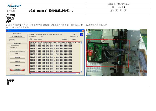
文件名称六 芯片读取及烧录 2.所选择程序读取正常后,将烧录器连接机台进行芯片烧录,注意事项1.取对应转接板插入所烧写程序,注意丝印上所印有型号,如C020配备2501B转接板,使用错误将无法烧录。
2.对所选择程序必须截图存档,方便每日程序点检及日后异常追溯。
4.将烧录器连接机台后,注意LED灯显示,黄色为烧录中,绿色为烧录完成,红色为不良.
作成部门
③编写/日期
②审核/日期
①批准/日期修订次数修 订日 期审 核日 期文件编号:XDD/SMT-0001
版 本:A.1
松翰(SONIX)烧录器作业指导书第 3 页 共 3 页
1 点击“读取OTP”按钮,会将芯片中的信息读出(如果芯片有加密则只能读出部分数
据),并显示在信息框中.
3.程序选取正确后必须读取1PCS芯片,点检芯片是否正确,并如实填写<烧录点检表>.。
sonix讲座1
• •
♦ 内置看门狗计数器 ♦ 双时钟系统提供4 种操作模式
• • • 外部高速时钟:RC,最大10MHz 普通模式:高/低速时钟同时运行 睡眠模式:高/低速时钟都停止 醒 外部高速时钟:晶体,最大16MHz 低速模式:只有低速时钟运行 绿色模式:定时器T0 周期性唤
•
♦ 封装(支持的芯片格式)
• • • • • SN8P2708A:DIP 48 pins,SSOP 48 pins SN8P2707A:QFP 44 pins SN8P2706A:PDIP 40 pins SN8P2705A:PDIP 32 pins,SOP 32 pins SN8P2704A:SK-DIP 28 pins,SOP 28pins
SN8P2700A 系列产品性能表
定时器
芯片型号 ROM RAM 堆栈 层数 I/O ADC DAC T0 TC0 TC1 Buzzer
PWM
SIO 唤醒功能 引脚数目 封装
SN8P2708A 4K*16 256
8
V V
V
36 8ch 1ch
2
1
11
DIP48/SSOP48
SN8P2707A 4K*16 256
1
VCC
参考国外的微控器使用法,他们都建议并联二颗电容,一颗为47 F/10V的 钽质电容(用于疏导大量供应电流)和一颗0.1 F的一般陶瓷电容(用于 滤除高频噪声)。
1.4 引脚说明
1.5 引脚电路图
2.存储器结构
• 2.1 程序存储器(ROM)
•
• • • •
SN8P2700A 程序存储器为OTP ROM,存储 器容量为4K*16-bit,可由12 位程序计数器 PC 对程序存储器进行寻址,或由专用寄存 器(R、X、Y 和Z)对ROM 进行查表访问。 所有4096 x 16 位程序存储器通常分为4 个 区域。 1-word 复位向量地址 1-word 中断向量地址 7-word 保留区域 4K words 通用区 所有的存储器分为3 个代码区: 0000H~0003H 用来执行复位向量; 0004H~0007H 系统保留;0008H~0FFDH 用来执行中断向量及保存指令的操作代码。 0008H 是中断服务程序的入口地址。
创意大气的欧美外国名称
创意大气的欧美外国名称创意大气的欧美外国名称公司名字以下是小编推荐给到大家创意大气的欧美外国名字,大家不妨参考参考。
(01)、外国TI(德州仪器)(02)、外国SONIX(松翰科技)(03)、外国奥戈丝AOGES(04)、外国惠特曼(Whitman)外国(05)、外国速易达Fasteasy(06)、外国Regina 里贾纳(07)、外国Cardiff 卡迪夫(08)、外国Thurso 瑟索(09)、外国REGALIFE(10)、外国Probelie诺贝丽(11)、外国MICRONAS(微开半导体)(12)、外国MAXIM(美信)(13)、外国CHILISIN(奇立新)(14)、外国FOXCONN ELECTRONICS(富士康)(15)、外国NATIONAL INSTRUMENTS(美国国家仪器公司)(16)、外国歌思奇GESCHE(17)、外国迪瑞杰(18)、外国瑞莱克斯RELAX(19)、外国SUNFREE 圣菲力(20)、外国纳斯卡nashco(21)、外国凯普邦(22)、外国OMRON(欧姆龙)(23)、外国Ulm 沃尔姆——简洁(24)、外国FREESCALE(飞思卡尔)(25)、外国Ownow恩利(26)、外国KEMET(基美)(27)、外国VIPEOR沃鹏(28)、外国尚嘉Sunjoy (29)、外国ACEGEM 天美健(30)、外国安格尔angel (31)、外国Jagco 捷购/快购(32)、外国ST(意法半导体)(33)、外国Vanice 万莱思(34)、外国REGALEAD(35)、外国RENESAS(瑞萨)(36)、外国HOLTEK(盛群)(37)、外国INFINEON(英飞凌)(38)、外国碧丝曼BISMAN (39)、外国Okwis傲威司(40)、外国Opiace恩派斯(41)、外国LINEAR(凌特公司)(42)、外国TEKTRONIX(泰克)(43)、外国娅洛尔YAROE (44)、外国捷讯特Jiexute (45)、外国ROHM(罗姆)。
SONIX M2IDE中文说明书

M2IDE 用户手册SONiX 8-Bit MCUM2IDE 用户手册Version 1.0SONiX 公司保留对以下所有产品在可靠性、 功能和设计方面的改进做进一步说明的权利。
SONiX 不承担由 本手册所涉及的产品或电路的运用和使用所引起的任何责任。
SONiX 的产品不是专门设计应用于外科植入、生 命维持和任何 SONiX 产品的故障会对个体造成伤害甚至死亡的领域。
如果将 SONiX 的产品应用于上述领域, 即使这些是由 SONiX 在产品设计和制造上的疏忽引起的,用户也应赔偿所有费用、损失、合理的人身伤害或死 亡所直接或间接产生的律师费用, 并且用户保证 SONiX 及其雇员、 子公司、 分支机构和销售商与上述事宜无关。
SONiX TECHNOLOGY CO., LTD.Page 1 of 74Version1.0M2IDE 用户手册修改记录版本 V1.0 时间 2009/8/18 修改说明 初版SONiX TECHNOLOGY CO., LTD.Page 2 of 74Version1.0M2IDE 用户手册目录修改记录 .............................................................................................................................................................................................. 2 目 录 .................................................................................................................................................................................................... 3 第 1 章 系统概要与安装 .................................................................................................................................................................... 5 1.1 M2IDE简介............................................................................................................................................................................ 5 1.2 安装 ....................................................................................................................................................................................... 6 1.2.1 系统配置需求............................................................................................................................................................ 6 1.2.2 硬件安装.................................................................................................................................................................... 6 1.2.3 软件安装.................................................................................................................................................................... 8 第 2 章 视窗界面 .............................................................................................................................................................................. 14 2.1 快速开始 ............................................................................................................................................................................. 14 2.2 菜单—文件/编辑/视图/调试/辅助/窗口/帮助选项 ........................................................................................................... 15 2.2.1 启动M2IDE系统 ..................................................................................................................................................... 15 2.2.2 M2IDE界面 .............................................................................................................................................................. 17 2.2.3 文件菜单(File) ................................................................................................................................................... 20 2.2.4 编辑菜单(Edit) ................................................................................................................................................... 23 2.2.5 视图菜单(View) ................................................................................................................................................. 26 2.2.6 调试菜单(Debug) ............................................................................................................................................... 27 2.2.7 应用菜单(Utility) ............................................................................................................................................... 30 2.2.8 窗口菜单(Window) ............................................................................................................................................ 32 2.2.9 帮助菜单(Help).................................................................................................................................................. 33 2.2.10 窗口管理................................................................................................................................................................ 34 2.3 创建和调试应用程序 ......................................................................................................................................................... 37 2.3.1 创建工程/新建文件................................................................................................................................................. 37 2.3.2 程序的编译和链接.................................................................................................................................................. 42 2.3.3 程序的运行与调试.................................................................................................................................................. 44 2.3.4 编译选项(Code Option选项) ............................................................................................................................. 49 2.3.5 工程文件类型.......................................................................................................................................................... 50 2.4 如何仿真LCD ..................................................................................................................................................................... 51 第 3 章 开发语言 .............................................................................................................................................................................. 52 3.1 指令集 ................................................................................................................................................................................. 52 3.2 伪指令 ................................................................................................................................................................................. 54 3.3 包含文档 ............................................................................................................................................................................. 55 3.4 宏 ......................................................................................................................................................................................... 56 3.5 条件编译控制 ..................................................................................................................................................................... 60 附录 .................................................................................................................................................................................................... 63 附录Ⅰ编译器错误信息说明 .................................................................................................................................................... 63 附录Ⅱ 菜单命令,工具和快捷方式一览表........................................................................................................................... 67 附录Ⅲ 伪指令表 ...................................................................................................................................................................... 70 附录Ⅳ 图片列表 ...................................................................................................................................................................... 71 附录Ⅴ相关FAQ ........................................................................................................................................................................ 73SONiX TECHNOLOGY CO., LTD.Page 3 of 74Version1.0M2IDE 用户手册前言在 SONiX 8 位微控器中,SN8P2XXX 系列开发系统采用的是在线仿真器(ICE),而 PC 机上运行的软件是 M2IDE 或 SN8 C Studio。
SONiX 8-Bit MCU SN8ICE 2K Plus II 说明书
SONiX 8-Bit MCUSN8ICE 2K Plus II使用说明书V1.0SONiX公司保留对以下所有产品在可靠性、功能和设计方面的改进做进一步说明的权利。
SONiX不承担由本手册所涉及的产品或电路的运用和使用所引起的任何责任。
SONiX的产品不是专门设计应用于外科植入、生命维持和任何SONiX产品的故障会对个体造成伤害甚至死亡的领域。
如果将SONiX的产品应用于上述领域,即使这些是由SONiX在产品设计和制造上的疏忽引起的,用户也应赔偿所有费用、损失、合理的人身伤害或死亡所直接或间接产生的律师费用,并且用户保证SONiX及其雇员、子公司、分支机构和销售商与上述事宜无关。
修正记录版本日期修改内容VER1.0 2009/07 第一版目录目录 (2)1.产品介绍 (3)1.1 产品性能特征 (3)1.2 产品标准配置 (3)2.硬件连接 (4)2.1 硬件产品介绍 (4)2.2 硬件连接步骤 (5)2.3 连接仿真转接板 (6)3.软件安装 (7)3.1 M2IDE 安装步骤 (7)3.2 USB 驱动程序安装 (10)4.使用注意事项 (13)5.简单故障处理方法 (15)6.应用及保修说明 (16)1.产品介绍SN8ICE2K Plus II 是SONiX的新一代开发工具产品,适用于SN8P2000系列8-bit MCU应用的实时硬件仿真,可为项目开发提供一个功能强大且稳定可靠的仿真环境。
本产品具有良好的兼容性和友好的人性化接口,能为新产品的设计提供一个方便的开发平台,具有很好的易用性和易操作性。
1.1 产品性能特征¾双FPGA设计,保证仿真器良好的兼容性和扩充性¾支持SN8P2000系列芯片的实时硬件仿真¾功能丰富的外接接口和扩充接口¾安装软件时自动安装驱动,无需额外手动安装¾采用USB方式与PC沟通传输数据1.2 产品标准配置¾SONiX SN8ICE2K Plus II(1台)¾ DC7.5V/2A 15W电源适配器(1个)¾ B Type USB线(1条)¾产品使用说明书(1份)¾电子配件(1袋),内附适当的短路帽、晶振、振荡匹配电容等¾ 28 Pin(窄)仿真排线(1条)2. 硬件连接2.1 硬件产品介绍仿真介面復位按鍵功能跳針電源指示燈電源開關晶振/電容更換處適配器USB 指示燈图2.1 产品连接示意图¾ 电源开关:打开/关闭SN8ICE2K Plus II 工作电源¾ 电源指示灯:打开SN8ICE2K Plus II 电源时,指示灯点亮显示红色 ¾ USB 指示灯:USB 成功连接后,指示灯显示绿色¾ 晶振与电容更换处: 此缺口用来快速更换适当的晶振与电容值¾功能跳针:z INTERNAL 5V :开/短路跳针,仿真芯片选择使用目标线路板电源/仿真器本身电源图2.2 INTERNAL 5Vz INTERNAL 3.3V:开/短路跳针,仿真芯片选择使用目标线路板电源/仿真器本身电源图2.3 INTERNAL 3.3Vz AVREFH/VDD:AVREFH为仿真芯片ADC线路的参考高电压。
SONIX
4 SN8P2700系列单片机
适用领域
电磁炉、空调、充电器等大、小家电以及各种需要ADC 和高抗干扰性的产品。
1.2.2 引脚排列和说明
1.2.2 引脚排列和说明
1.2.2 引脚排列和说明
1.2.2 引脚排列和说明
1.3SONIX单片机的内部结构
1.3.1 CPU结构
CPU即为中央处理单元,是整个单片机的中枢。由算 术逻辑单元(ALU)、控制单元和专用寄存器组三部 分组成 。
SN8P1604A 4K*16
128
4
- - V 22
1
11
10 SKDIP28/SOP28
1 SN8P1600系列单片机
1)应用特征
最大可达4K*16 ROM 48~128字节RAM 可编程设置上拉电阻的I/O口 内置上电复位、低电压检测电路 内置看门狗定时器 59条简单有效的指令
2)适用领域
2)适用领域
电子秤、血压计等电子测量产品
4 SN8P1900系列单片机
SN8P1900系列单片机是SONIX公司最新推 出的片内带16位ADC、LCD驱动器、高速低 功耗8位单片机。
4 SN8P1900系列单片机
1)应用特性 内置Δ-Σ型16位ADC 内置高速PWM/BUZZER接口 内置高速SIO口 内置4*32 LCD 驱动
ADC、DAC、PWM或BUZZER输出、内置SIO通 讯口、LCD DRIVER、WATCH DOG计时器、内 置LVD 电路。
SONIX单片机命名规则
SN8 X XXXX X X XXX 1 2 345
1:存储器类型: P表示存储器为OTP一次可编程 性 A表示MASK型,即掩模型。
2:型号:SONIX系列命名,用4位表示 3:增强型号:一般后面加字母A 表示增强型。 4:封装形式: Q: QFP P: PDIP K: SKDIP
SONIX Pm10 产品说明书
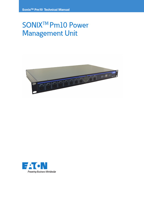
SONIX TM Pm10 Power Management Unit2PA/GA Power Management unitSONIX Pm10 TECHNICAL mANUAL TM365-1 / A June 2022 Contents 1 INTRODUCTION . . . . . . . . . . . . . . . . . . . . . . . . . . . . . . . . . . . . . . . . . . . . . . . . . . . . . . . . . . . . . . . . . . . . . . . .41.1 Eaton quality assurance ......................................................................41.2 About the product ..........................................................................41.3 Key features . (4)2 BEFORE YOU BEGIN . . . . . . . . . . . . . . . . . . . . . . . . . . . . . . . . . . . . . . . . . . . . . . . . . . . . . . . . . . . . . . . . . . . . .42.1 Packaging .................................................................................42.2 Safe working practice .......................................................................42.3 In the box ................................................................................42.4 Required tools .............................................................................42.5 Recommended spares . (4)3 UNIT OVERVIEW . . . . . . . . . . . . . . . . . . . . . . . . . . . . . . . . . . . . . . . . . . . . . . . . . . . . . . . . . . . . . . . . . . . . . . .53.1 Front panel layout ..........................................................................53.2 Rear panel layout ...........................................................................53.3 Specifications .............................................................................53.3.1 Weight and dimensions ...................................................................53.3.2 Power and utility ........................................................................53.3.3 Environmental operating conditions (5)4 INSTALLATION AND CONNECTIVITY . . . . . . . . . . . . . . . . . . . . . . . . . . . . . . . . . . . . . . . . . . . . . . . . . . . . . . .64.1 Physical installation .........................................................................64.2 Power Bus ................................................................................74.3 AC power input ............................................................................94.4 AC power output ...........................................................................74.4.1 Outputs 1 to 8 .........................................................................124.4.2 Auxiliary output ........................................................................134.5 48 V dc power distribution ..................................................................134.6 Fault output ..............................................................................144.7 Fusing . (15)5 SETUP AND CONFIGURATION . . . . . . . . . . . . . . . . . . . . . . . . . . . . . . . . . . . . . . . . . . . . . . . . . . . . . . . . . . .166 UNIT OPERATION . . . . . . . . . . . . . . . . . . . . . . . . . . . . . . . . . . . . . . . . . . . . . . . . . . . . . . . . . . . . . . . . . . . . . .166.1 Power loss protection ......................................................................166.2 AC Power input status indication. . . . . . . . . . . . . . . . . . . . . . . . . . . . . . . . . . . . . . . . . . . . . . . . . . . . . . . . . . . . . .166.3 Power Outputs indication ...................................................................166.4 Auxiliary Output ...........................................................................166.5 DC Rack Output ..........................................................................166.6 Front panel button operation .................................................................176.7 Front panel display. . . . . . . . . . . . . . . . . . . . . . . . . . . . . . . . . . . . . . . . . . . . . . . . . . . . . . . . . . . . . . . . . . . . . . . . .177 UNIT CUSTOMISATION . . . . . . . . . . . . . . . . . . . . . . . . . . . . . . . . . . . . . . . . . . . . . . . . . . . . . . . . . . . . . . . . .178 COMMISSIONING/TESTING . . . . . . . . . . . . . . . . . . . . . . . . . . . . . . . . . . . . . . . . . . . . . . . . . . . . . . . . . . . . .179 MAINTENANCE . . . . . . . . . . . . . . . . . . . . . . . . . . . . . . . . . . . . . . . . . . . . . . . . . . . . . . . . . . . . . . . . . . . . . . .183PA/GA Power Management unitSONIX Pm10 TECHNICAL mANUAL TM365-1 / A June 2022 1.1 List of FiguresFIGURE 1 . GENERAL, SIMPLIFIED VIEW OF THE SONIX PM10 FRONT PANEL . . . . . . . . . . . . . . . . . . . . . . . . . . . . . . . . .8FIGURE 2 . GENERAL, SIMPLIFIED VIEW OF THE SONIX PM10 REAR PANEL . . . . . . . . . . . . . . . . . . . . . . . . . . . . . . . . . . .8FIGURE 3 . STACKING PM10 WITH OTHER SONIX UNITS . . . . . . . . . . . . . . . . . . . . . . . . . . . . . . . . . . . . . . . . . . . . . . . . . .10FIGURE 8 . PM10 POWERED FROM TWO REDUNDANT POWER SUPPLIES . . . . . . . . . . . . . . . . . . . . . . . . . . . . . . . . . . .11FIGURE 9 . PM10 POWERED FROM A SINGLE POWER SUPPL Y . . . . . . . . . . . . . . . . . . . . . . . . . . . . . . . . . . . . . . . . . . . . .12FIGURE 10 . CONNECTING SONIX 350-D TO THE OUTPUTS . . . . . . . . . . . . . . . . . . . . . . . . . . . . . . . . . . . . . . . . . . . . . . .13FIGURE 11 . AUXILIARY OUTPUT . . . . . . . . . . . . . . . . . . . . . . . . . . . . . . . . . . . . . . . . . . . . . . . . . . . . . . . . . . . . . . . . . . . . .13FIGURE 12 . 48 V DC POWER DISTRIBUTION BETWEEN TWO PM10 UNITS . . . . . . . . . . . . . . . . . . . . . . . . . . . . . . . . . . .14FIGURE 13 . FAULT OUTPUT . . . . . . . . . . . . . . . . . . . . . . . . . . . . . . . . . . . . . . . . . . . . . . . . . . . . . . . . . . . . . . . . . . . . . . . . . .15List of TablesTABLE 1 . FRONT PANEL INDICATORS AND SWITCHES . . . . . . . . . . . . . . . . . . . . . . . . . . . . . . . . . . . . . . . . . . . . . . . . . . . .8TABLE 2 . REAR PANEL CONNECTIONS . . . . . . . . . . . . . . . . . . . . . . . . . . . . . . . . . . . . . . . . . . . . . . . . . . . . . . . . . . . . . . . . .8TABLE 3 . FAULT OUTPUT STATES . . . . . . . . . . . . . . . . . . . . . . . . . . . . . . . . . . . . . . . . . . . . . . . . . . . . . . . . . . . . . . . . . . . .15TABLE 5 . FRONT PANEL POWER INPUT STATUS INDICATORS . . . . . . . . . . . . . . . . . . . . . . . . . . . . . . . . . . . . . . . . . . . . .16TABLE 6 . FRONT PANEL POWER OUTPUTS STATUS INDICATORS . . . . . . . . . . . . . . . . . . . . . . . . . . . . . . . . . . . . . . . . . .16TABLE 9 . FRONT PANEL DC RACK OUTPUT STATUS INDICATORS . . . . . . . . . . . . . . . . . . . . . . . . . . . . . . . . . . . . . . . . .17TABLE 10 . MEASUREMENT INDICATION LED . . . . . . . . . . . . . . . . . . . . . . . . . . . . . . . . . . . . . . . . . . . . . . . . . . . . . . . . . .174PA/GA Power Management unitSONIX Pm10 TECHNICAL mANUAL TM365-1 / A June 2022 1 Introduction These instructions are intended for all users who will have to install, commission, configure and setup the Sonix Pm10 power management unit. It is assumed that you have necessary electrical, electronic and telecommunications experience to undertake the work. If in doubt, please speak to your local Eaton representative.1.1 Eaton quality assuranceEaton design, manufacture, installs and commission all our products to the highest standards of quality. This quality process is embraced and adopted throughout the group in all areas of our operations.This is demonstrated by our compliance and strict adherence to ISO 9001, 14001, ATEX, IECEX policies. On receipt of the product, ensure that the cartons are undamaged and that the contents are all correct and complete.Should this product reach you in an unsatisfactory condition please report this to Eaton to enable us to rectify and investigate the fault in a speedy manner.1.2 About the productSonix Pm10 is a compact 19” 1U design unit, housing the circuitry for power distribution, switchover andmanagement for the Sonix PA/GA system components. Output power is individually protected, monitored and efficiently and securely distributed between eight main AC outputs, one auxiliary AC output and one 48 V DC output, providing all PA/GA system power needs in a single and compact enclosure.For high criticality systems that require duplicated AC power inputs, Sonix Pm10 ensures that PA/GA system is always operational and in the event of site supply failure or dangerous fluctuations, the system will automatically switch over to the standby power supply. Even under full load operation, this is achieved without any disruption to the system operation, continuously advising the unit status via comprehensive unit display.Input and output power connections to the Pm10 unit is via shake proof plug and socket, ensuring simple and speedy connectivity of the unit and ease of maintenance.1.3 Key featuresSonix Pm10 is designed to provide the following features:• Highly efficient 1U package • 110 / 230 V ac compatible •8 outputs• 48 V dc output• High integrity power supply and cable monitoring • Failsafe rapid dual supply switchover• Voltage and current monitoring / indication•Visual status indication and remote fault reporting2 Before you begin2.1 PackagingIn the interest of preserving the environment, Eaton aims to use recycled packaging wherever practical. Due to the physical nature of our products, we provide adequate packaging to protect the goods during transit. Please ensure that once unpacked, checked and installed that all packaging is disposed of or recycled in a responsible manner.2.2 Safe working practiceWhilst working on or within the Sonix PA/GA system it is our prime interest that you remain safe throughout. During this work you may be exposed to potentially hazardous voltages, currents, confined spaces and potentially hazardous industrial environments. Prior to undertaking any work please ensure relevant permits and regulations are adhered to.2.3 In the box• 1 x Sonix Pm10 unit.•1 x Technical Manual2.4 Required tools• Flat blade screw driver (0.6x3.5) – for plug wiring.•Appropriate screw driver for cage-nut fixings.2.5 Recommended sparesUser replaceable fuses:• Eaton Bussmann Time delay 2A S505-2R •Eaton Bussmann Time delay 4A S505-4R5PA/GA Power Management unit3 Unit overview3.1 Front panel layout6PA/GA Power Management unitSONIX Pm10 TECHNICAL mANUAL TM365-1 / A June 2022 can be either M5 or M6 fitted through four mounting it will require to be installed on shelves or other weightA – Rack frame – 19”B – Additional Sonix PA/GA unitsC – Unit fixingsD – Shelf or other weight support structure. Compulsory for units supporting amplifiers.Figure 3. Stacking Pm10 with other Sonix units.ote: N Recommended fixing screw length is 16 mm, complete with washers.Warning: Ensure that no ventilation points are obstructed, and that the module is correctly supported within the cabinet.IEC 60417-6043 (2011=01)Beware of sharp edges and corners!Take care while handling.7PA/GA Power Management unitSONIX Pm10 TECHNICAL mANUAL TM365-1 / A June 2022 4.2 AC power inputWarning: High voltages present. Isolate power supply elsewhere before connecting the unit.Warning: Unit MUST be earthed via AC PowerEach individual Pm10 unit is powered by either one or two redundant ac power sources connected to Primary and Secondary power inputs. In both cases, the incoming power feed must be protected by at least one 32 A RCBO, as per diagrams below.Incoming power supply110 V ac 230 V acFigure 8. Pm10 powered from two redundant power supplies.8PA/GA Power Management unitSONIX Pm10 TECHNICAL mANUAL TM365-1 / A June 2022 The Pm10 unit will instantly and reliably switch between the primary and secondary power inputs.Although it is possible for power supplies to vary between primary and secondary inputs (i.e. 110 V ac on primary and 230 V ac on secondary), that confi guration is not recommended due to the need for de-rating of 350-d units present in the system – see 350-d Technical Manual for more details.Warning: Minimum required wire diameter forboth Primary and Secondary input is 4 mm 2. Power cable must include an adequately sized Earth conductor, connected to protective earth.ote: N As these cables are power feeds, they should be, wherepossible, routed within the PA/GA system in a separate way to avoid contact with dc power or audio cables and reduce the possibility of interference.Maximum supported wire diameters for both primary and secondary plugs are:• Solid: up to 16 mm 2•Stranded:• including sleeved ferrule: up to 10 mm 2• including non-sleeved ferrule: up to 16 mm 2•Connection method: Push-in spring connection •Stripping length: 18 mmWarning: Non-solid cables MUST be ferruleddue to use of spring-clamp retaining mechanism.Warning: Observe the polarity / order of connections.Incoming power supply110 V ac 230 V acFigure 9. Pm10 powered from a single power supply.9SONIX Pm10 TECHNICAL mANUAL TM365-1 / A June 2022 10PA/GA Power Management unitSONIX Pm10 TECHNICAL mANUAL TM365-1 / A June 2022 4.4 48 V dc power distribution48 V dc power is generated internally by an ac to dc power supply, switched live between the power inputs. The output voltage is regulated to +/- 0.5% and is used for all PA/GA system dc power needs. Total load should not exceed 95W.Current limit for individual 48 V dc output is 2 A,protected by replaceable fuse located on the front panel (see Figure 1).When more than one Pm10 unit is being used in the system, their 48 V dc rail can be shared between the units. To achieve this, the Pm10 units DC outputs are daisy-chained: 48 V dc output of the first unit isconnected to 48 V dc input of the next unit, with no limit on how many units can be chained. The 48 V dc output from the last unit is then used as a primary power source for PA/GA 48 V dc with the others providing a redundant supply .Warning: If utilising the 48 V output in user touchable equipment an isolating DC:DC power supply is required.Figure 12. 48 V dc power distribution between two Pm10 units.ote: N These cables are power feeds. They should be, wherepossible, routed within the PA/GA system in a separate way to avoid contact with ac power or audio cables and reduce the possibility of interference.Maximum supported wires are:• Solid: 1.5 mm 2•Stranded:• including sleeved ferrule: 0.5 mm 2• including non-sleeved ferrule: 1.5 mm 211PA/GA Power Management unitSONIX Pm10 TECHNICAL mANUAL TM365-1 / A June 2022 4.5 RJ45 Power BusThe Power bus connections are reserved for future expansion.4.7 Fault outputThe fault output on the Sonix Pm10 is a volt-free contact output. The state of the fault output is determined byhealth of the AC inputs to the unit:T able 3. Fault output states.Fault output will hold its state for approximately 10 seconds before clearing after any fault has cleared, to allow any transient faults to be registered by any external monitoring.ote: N There is no configuration option to change the sense of the output.Maximum cable section supported are:• Solid: 1.5 mm 2•Stranded:• including sleeved ferrule: 0.5 mm 2• including non-sleeved ferrule: 1.5 mm 24.8 FusingIn addition to the set of external fuses for outputprotection, the Sonix Pm10 is equipped with two internal fuses to protect the unit itself:12PA/GA Power Management unitSONIX Pm10 TECHNICAL mANUAL TM365-1 / A June 2022 5 Setup and Configuration Sonix Pm10 unit does not have any external switches nor jumper links to set.All units come pre-configured with a general setup to support a secondary input but prefer primary. If a different configuration is required, please contact your local Eaton representative.6 Unit operation6.1 Power loss protectionWhen the Sonix Pm10 unit detects an AC power loss on the active input, it will immediately begin swapping all the outputs to use a redundant AC input, if available. When a preferred input becomes available again, the unit will wait for at least 10 seconds before swapping back. This delay is intended to allow the input tostabilise, to avoid switching during surges from other loads and to ensure the supply will remain available and will not immediately fail again.ote: N There will be a finite gap in supply power while the unit is carefully switching inputs, this is to ensure that the two supplies are not connected together.ote: N Output voltage is dependent on which input is currently selected. All outputs will have the same source.6.3 AC Power input status indicationPm10 reports the status of its AC power inputs via pairs of green and red LEDs grouped with each input (seeFigure 1), as per table below:T able 4. Front panel power input status indicators.6.3 Power Outputs indicationPm10 reports the status of its outputs via pairs of green and red LEDs grouped with each output (see Figure 1),as per table below:T able 5. Front panel power outputs status indicators.Fuse monitoring for Pm10’s individual outputs can be disabled in the configuration via SAS (please refer to SAS Product Manual for details). The unit will still be protected, but the status of the output(s) will not be reported.6.4 Auxiliary OutputWarning: High voltages present. Power down Pm10 unit before connecting or disconnecting this output.This output is available as a reliable AC power source for other equipment in the PA/GA rack, for example fans and air conditioning.Warning: Observe load limit of 4 A on unit and avoid connecting items with high inductive loads. These typically have high surge currents.6.5 DC Rack OutputThis is a regulated 48 V dc output, dedicated as a power source for other Sonix units that are dc powered, such as Hmi or Vw2.Pm10 reports the status of its DC Rack Output via pairof green and red LEDs (see Figure 1), as per table below:T able 6. Front panel dc rack output status indicators.6.6 Front panel button operationThe Sonix Pm10’s front panel button has three functions:1. Selecting measurements – each short press toggles between Voltage and Current measurements and presents the result on the front panel display (see Figure 1).2 Initiate local fault reset – long-press of the button will reset all fault flags on the unit. If the fault is still present, it will get reintroduced after few seconds.13PA/GA Power Management unitSONIX Pm10 TECHNICAL mANUAL TM365-1 / A June 2022 6.7 Front panel displaySonix Pm10 is equipped with front panel display to show life-time measurements of input supply voltage and overall current. Green LED indicates the currentoperation, as per table below:T able 7. Measurement indication LEDote: N The display is not calibrated and serves only as an indication. Measurements for maintenance and fault-finding purposes need to be taken with calibrated equipment.7 Unit customisationIndividual unit customisation is not available for this unit.8 Commissioning/testingBefore starting commissioning or testing, check that:• Unit is correctly earthed,•Connection of each cable to and from the system is correct and the cables are not damaged,• DC input and output ports have the correct polarity,•There are no short circuits between negative and positive conductors,• Each input is fed via a suitably rated RCBO,•Live and Neutral are correctly connected to the relevant inputs.9 MaintenanceWarning: High voltages present. Power off the system and isolate power input supply before proceeding.Although the Sonix Pm10 unit does not require anyspecific maintenance, the following program represents the minimum care and it is advisable that it will be performed monthly:•Check the unit for visible damage (scratches or bumps).• Check unit fixing to the rack – tighten loose screws.•Check connections and cable integrity - replace damaged cables and push in loosened plugs.•Remove dust and dirt from front panel - clean with a dry cloth.ote: N Do not use sharp objects. Do not use water, aggressive cleaning agents or solvent to clean the unit.All specifications, dimensions, weights and tolerances are nominal (typical) and Eaton reserve the right to vary all data without prior notice.No liability is accepted for any consequence of use.EatonUnit B, Sutton Parkway Oddicroft Lane Sutton in Ashfield United Kingdom NG17 5FBT : +44 (0) 1623 444 /hac *******************© 2022 EatonAll Rights Reserved Printed in UK PublicationNo.TM365-1 / A June 2022Eaton and SONIX™ are registered trademarks.All other trademarks are property of their respective owners.Changes to the products, to the information contained in thisdocument, and to prices are reserved; so are errors and omissions. Only order confirmations and technical documentation by Eaton is binding. Photos and pictures also do not warrant a specific layout or functionality. Their use in whatever form is subject to prior approval by Eaton. The same applies to Trademarks (especially Eaton, Moeller, and Cutler-Hammer). The Terms and Conditions of Eaton apply, as referenced on Eaton Internet pages and Eaton order confirmations.。
sonix品牌

ISPRM世界大会首次落户中国声波振动领衔技术革新潮流
Sonix声波振动运动机是由韩国IP明星企业索尼克世界株 式会社通过不断地研究和技术开发后推出的创新产品,在全球 拥有14项技术专利。声波振动运动机最初被前苏联用于航天员 的训练保健,由于对身体的保健和恢复功能明显,很快就在专 业运动员中间推广普及,近几年已经发展成为医院康复锻炼的 重要器材,并进入了欧美上流社会的家庭,成为引领欧美运动 保健潮流的标志产品。 韩国sonix声波振动运动机革新性地将电磁技术和声响原 理运用到人体康复领域,通过声波产生精密垂直振动,使身体 内被堵塞的能源和淋巴细胞能顺畅移动,增加细胞内的生物能 源,保护及强化骨质和肌肉。使用韩国sonix声波振动运动机 十分钟,就可以获得等同一个90分钟太极拳运男Ч佣 谑夷诰涂梢郧崴傻厥迪纸】翟硕哪康摹 据了解,韩国sonix声波振动运动机即使在高频率和低频 率宽中也可以很有效的运作,使用者可根据每个人自身的情况, 随意调整频率和强度。另外,声波振动技术有效地解决了机械 运动所具有的粗糙和暴力的问题,通过声波振动使人体得到均 衡的运动效果,避免了机械运动可能对人体带来的伤害,已成 为新时代最先进的技术,是振动运动器材中出类拔萃的革新产 品。
韩国sonix声波振动运动机
ISPRM世界大会首次落户中国
国际物理医学与康复医学学会(简称:ISPRM)是 全球最权威的康复保健行业组织,会员覆盖了全球康复 保健领域最顶尖的科学家、医生和医疗机械研发企业, 代表着该领域中全球最新的技术潮流和科研成果。近年 来,随着韩国sonix声波振动运动机等高科技产品的引入 和广泛使用,中谖锢硪窖Ш涂蹈匆窖Я煊虻牡匚蝗找 嫣嵘晌狪SPRM重要的成员国。ISPRM将大会定在 中国首都北京举行,再次证明了中国在世界物理医学和 康复医学上举足轻重的地位。 随着国家对康复医学的重视,在政策与市场的双重 推动下,逐步形成了在成熟的医疗保健体系制度引导下, 政府和民间资本共同发展的格局,中国特色的康复医学 也渐渐成型,诞生了以韩国sonix声波振动运动机为代表 的众多高科技康复保健产品,在世界上建立起中国在高 端康复医学领域的把控能力。
sonix 物理康复的应用(案例)
SONIX物理康复应用(案例)康复(rehabilitation)这一名词是从西方传过来的,是20世纪中期出现的一门新兴的学科。
它是一门以消除和减轻人的功能障碍,弥补和重建人的功能缺失,设法改善和提高人的各方面功能,尽可能去除由疾病或外伤所引起的身心的伤害,目的是尽量使患者恢复作为社会一员的正常生活。
是功能障碍的预防、诊断、评估、治疗、训练和处理的综合的医学学科。
为了能够使患者回归社会,康复不只包括医学方面的康复,而且还包括心理的、社会的、经济的、职业的、教育的等多方面的康复。
康复方法针对不同的疾病和疾病的不同阶段,康复的方法也是丰富多彩的。
包括:物理治疗、运动疗法、作业疗法、语言治疗、心理治疗、职业疗法、康复工程等。
其中物理疗法是非常重要的康复治疗手段。
物理治疗的作用1、消炎:如对急性炎症可选用紫外线、微波、超短波疗法,对亚急性或慢性炎症可选用短波、红外线疗法。
2、镇痛:如磁疗、干扰电疗法、经皮神经电刺激疗法均有显著的镇痛作用。
3、镇静:水疗、电睡眠疗法、空气负离子疗法等。
4、兴奋作用:如低频及中频电疗法可以治疗肌萎缩。
5、改善血液循环:水疗、直流电疗法、高频电疗法等都可引起人体组织充血反应。
6、调节植物神经及内脏功能。
7、松解粘连及软化瘢痕:超声波、音频电疗法均有明显的松解粘连及软化瘢痕作用。
8、杀菌:例如紫外线疗法。
9、治癌:高频、微波、热疗等方法对治疗癌症有一定效果。
物理疗法的优越性50年代初,人们注意到物理因子在保健和疾病治疗方面有其独到的作用,尤其在亚健康状态的治疗中,显示出不可比拟的优越性。
随着科技的发展,物理因子治疗的设备及手段也日趋完善。
首先,各种物理因子直接作用于身体各部位,能够改善局部的不适感及症状,如颈、肩、腰、腿痛,浑身无力、肥胖、便秘等,并有加快血液循环,促进有毒及致痛物质排出体外的作用。
物理因子在亚健康状态的治疗中作用不可取代。
Sonix物理康复应用:sonix依靠电磁技术和声响原理产生精密垂直振动,在高频率和低频宽中,能够根据每个人的自身条件随意调整频率和强度,它的全身振动与局部振动技术对人体各部位神经、肌体受损后康复几理疗有巨大临床价值:。
sonix烧录器培训资料

sonix烧录器培训资料Sonix烧录器是一种通用的烧录器,它支持多种芯片类型,包括Flash、EEPROM、SRAM等。
它可以通过USB接口与计算机连接,使用户能够轻松地将程序代码烧录到芯片中。
Sonix烧录器具有高速、稳定、可靠的特点,适用于开发板、单片机、嵌入式系统等领域。
Sonix烧录器的工作原理是通过USB接口与计算机通信,接收计算机发送的烧录指令和数据,并将其转换为芯片能够识别的电信号,然后将电信号传输到芯片中实现烧录。
同时,Sonix烧录器还可以从芯片中读取数据,并将其传输到计算机中进行分析和处理。
将Sonix烧录器通过USB接口连接到计算机上,然后打开电源开关。
此时,计算机将会自动识别Sonix烧录器,并安装驱动程序。
在Sonix烧录器的操作界面中选择需要烧录的芯片类型。
在选择芯片类型时,需要提供芯片的型号、厂商等信息。
在计算机上打开相应的编程软件,将要烧录的程序代码加载到计算机中。
在加载程序代码时,需要注意程序代码的格式和编译选项是否与芯片兼容。
在Sonix烧录器的操作界面中选择需要烧录的芯片型号和端口号,然后单击“开始烧录”按钮。
此时,Sonix烧录器将会将程序代码烧录到芯片中。
在烧录过程中,需要注意观察烧录进度和状态信息。
在烧录完成后,可以使用Sonix烧录器读取芯片中的数据。
在读取数据时,需要注意数据的格式和解析方式是否正确。
蛋鸡养殖业是一个具有巨大潜力的行业,随着消费者对高品质鸡蛋的需求不断增加,蛋鸡养殖业也在不断发展和壮大。
为了提高蛋鸡养殖的产量和品质,许多养殖户会参加蛋鸡培训课程。
本文将介绍一些蛋鸡培训资料,帮助养殖户更好地了解蛋鸡养殖技术。
选择适合当地气候、土壤条件的蛋鸡品种是养殖成功的关键。
不同品种的蛋鸡对饲料、管理、疾病抵抗力等方面都有所不同。
因此,养殖户需要根据当地的气候、市场需求以及自己的实际情况选择合适的蛋鸡品种。
蛋鸡需要摄取足够的营养才能正常生长和产蛋。
SONIX(韩国)声波振动机原理剖析
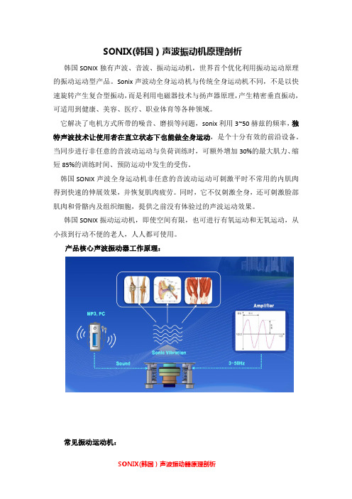
SONIX(韩国)声波振动机原理剖析
韩国SONIX独有声波、音波、振动运动机,世界首个优化利用振动运动原理的振动运动型产品。
Sonix声波动全身运动机与传统全身运动机不同,不是以快速旋转产生复合型振动,而是利用电磁器技术与扬声器原理,产生精密垂直振动,可适用到健康、美容、医疗、职业体育等各种领域。
它解决了电机方式所带的噪音、磨损等问题,sonix利用3~50赫兹的频率,独特声波技术让使用者在直立状态下也能做全身运动,是个十分有效的前沿设备。
当同步进行非任意的音波动运动与负荷训练时,可额外增加30%的最大肌力、缩短85%的训练时间、预防运动中发生的受伤。
韩国SONIX声波全身运动机非任意的音波动运动可刺激平时不常用的内肌肉得到快速的伸展效果,并恢复肌肉疲劳。
同时,它不仅刺激全身,还可刺激脸部肌肉和骨骼内及组织细胞,提供之前没有体验过的声波运动效果。
韩国SONIX振动运动机,即使空间有限,也可进行有氧运动和无氧运动,从小孩到行动不便的老人,人人都可使用。
产品核心声波振动器工作原理:
常见振动运动机:
声波振动核心优势:
声波振动运动机的作用:。
SONIX使用说明以及注意事项

SONIX的使用说明以及注意事项韩国SONIC WORLD研发的SONIX音波动全身运动机是利用索尼克世界独有电磁器技术与音响扬声器而制造的,它与传统的全身运动机不同,不是以快速旋转产生复合型振动,而是利用电磁器技术与扬声器原理,产生超低频率的声波,传达给人体的尖端科学。
它解决了电机方式所带的噪音、磨损等问题,是世界首个优化利用振动运动原理的产品。
SONIX的装箱清单一般包括主机、机身和机板,另外还有一些小零件:电源线1条、遥控器1个、音箱连接线1条、“T”型扳子1个、扳子螺栓8个、调节水平垫3个、使用说明书1本。
检查完清单之后,就可以安装了,安装过程中需要注意以下事项:1、不得装在湿气多的地方或者安装在有可能与水分接触的阳台附近;2、安装产品时,应与墙面有20cm以上的距离;3、应安装在既坚固又水平的地方;4、需检查产品表面表示的最大电子容量和使用的插座的电子容量是否充足;5、搬运产品时,应使用搬运专用工具,随意搬运会损坏产品。
正确安装完毕之后就可以放心使用了,但在使用过程中也需要注意以下事项:1、不稳定的姿势时使用运动器,或者突然运动时,会给身体带来负担,所以在正确姿势下,按开始按钮;2、运动器在起动时,从运动器上离开,会有危险,因此必须先按停止按钮,确认该运动器完全被停止后,再离开运动器;3、为防止浪费耗电,不使用机器时,请将电源线拔掉;4、起动产品时,在机板上蹦跳,会造成人身伤害;5、老年人或儿童使用本产品时,需保护人看护及留意;6、预防产品的破损或操作错误,不得随意拆卸,随意修理,改造产品。
维护和保管方法:1、不可在产品附件放置引火物质;2、不可向机器直接喷洒水分或用纯苯、稀释剂、消毒剂来清洁产品;3、清洁产品前,必须将电源插拔掉;4、清洁时,不可让水进入机器内部,用干布擦拭产品;5、清洁产品外壳时,应使用合适产品材质的清洁剂;6、长时间不使用产品时,应清洁产品外壳及干燥后再进行保管。
Krix Sonix Mk3 家庭影院音箱说明书

SONIX MK3 Producing dialogue with exceptional precision, this speaker was specifically designed to be used in home theatre systems. With its subtle design, the Sonix Mk3 blends into its surroundings.High frequencies are delivered by a 26mm ring radiator tweeter, with central waveguide for improved intelligibility and transparency. Bass and midrange are delivered by dual 100mm drivers, with dual front ports releasing bass energy forward – making it ideal for placing inside your TV cabinet. Perfectly sized for placement around AV components, the Sonix Mk3 is designed to slip neatly into most TV cabinets and joinery, allowing your screen to be the hero.For the ultimate sound experience at home, play it through Krix.FEA TURES•Compact size fits most TV cabinets •Bring movie dialogue to life • No more need for TV speakersSonix Mk3Frequency Range65Hz - 40kHz (in room response)Power Handling20 - 140 Watts RMS recommended amplifier power Sensitivity88dB (2.83V / 1m)ImpedanceNominal 6 Ohms (Minimum 4.2 Ohms)ConfigurationD’A ppolito, 2-way Low Frequency Driver2 x nominal 100mm (4") doped paper cones. 26mm (1") voice coil wound on high powered aluminium former High Frequency Driver26mm (1”) dual concentric diaphragm with wave-guide, centre plug for controlled directivity Enclosure TypeBass reflex, front vented with internal X bracing Vent LocationFront Dimensions125mm high x 435mm wide x 160mm deep Net Weight 4kgCENTRE CHANNELFINISHESBlack Woodgrain Sonix Mk3 Specifications Sheet-001。
