2SJ594中文资料
SAE J 594中文版

SAE J594 回复反射器中文译本-2018年6月版本文件进行了修订,以更新各种参考资料并修复小的印刷错误。
此外,删除了第7.1节“光度设计指南”,因为它不是必需的。
此外,图2的光度要求将1.5度观察角的(0,0)入射角值从6更改为7。
根据以往的历史,当原始光度表被更改为添加每入射勒克斯的最小毫坎德拉要求,以使用国际单位标准化文件时,该值被四舍五入而非四舍五舍五入。
与使用乘数转换单位的其他最小值的计算相比,这使得该特定值不正确。
这一变化很小,但应予以注意。
SI单位和英制单位之间的换算计算现已作为注释包含在内。
此外,还增加了投影仪光源CCT(相关色温)的公差,到目前为止还不存在。
此外,还添加了图1A和1B,以帮助演示测量的入射角与观察角的概念。
添加图1C是为了描述一种可接受的方法,该方法通过使用校准投影仪光源和使用分光辐射计的光纤布置来测量测试项目的反射颜色。
1.范围本SAE标准提供了回复反射器的试验程序、要求和指南。
2.参考文献2.1适用文件以下出版物在本文规定的范围内构成本规范的一部分。
除非另有说明,否则应使用SAE出版物的最新版本。
2.1.1SAE出版物可从SAEInternational购买SAEJ575总宽小于2032mm的车辆上使用的照明装置和部件的试验方法和设备SAEJ576塑料材料或机动车透镜和反射镜等光学零件用材料照明设备SAEJ578颜色规格SAEJ759照明识别代码2.2相关出版物以下出版物仅供参考,并非SAE技术报告的必要组成部分。
2.2.1SAE出版物可从SAEInternational购买SAEJ585总宽小于2032mm的机动车用尾灯(后位灯)总宽小于2032mm的机动车用SAEJ586制动灯总宽小于2032mm的机动车用SAEJ588转向信号灯总宽小于2032mm的道路车辆用SAEJ592示宽灯SAEJ2040总宽大于等于2032mm的车辆用尾灯(后位灯)总宽大于等于2032mm的车辆用SAEJ2041回复反射器SAEJ20422032mm或以上机动车用示廓灯、侧标志灯和识别灯宽度SAEJ22612032mm或以上机动车用刹车灯和前后转向信号灯总宽度SAEJ2442道路车辆车外灯和回复反射装置安装的协调规定摩托车除外2.2.2联邦出版物可从美国政府印刷办公室文件总监处获得联邦机动车安全标准标题49,CFR571.1083.定义3.1反射反射器车辆上使用的装置,通过接近车辆前照灯的反射光向接近的驾驶员显示存在。
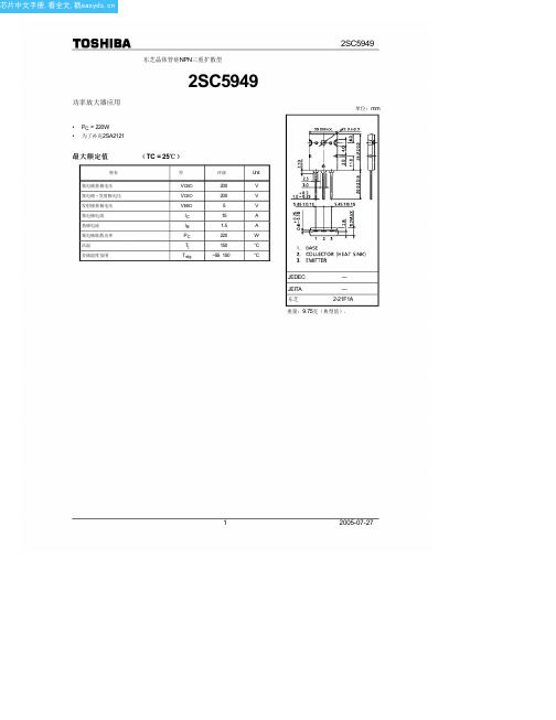
2SC5949中文资料(toshiba)中文数据手册「EasyDatasheet - 矽搜」
300
FE
Tc = 100°C
100 25
50 −25
30
DC电流增益^ h
10
hFE的 - 我C
5
0.03
0.1
0.3
1
3
10
30
集电极电流Ir IC / IB = 10 V
1
VCE (sat) – IC
0.5
0.3
(V)
Tc = 100°C
集电极 CE
(A)
IC max(pulsed) *
C
10 IC max(continuous)
DC operation Tc = 25°C
1 ms * 10 ms * 100 ms *
集电极电1流I
*:Single non-repetitive pulse
Tc = 25°C
Curves must be de-rated
芯片中文手册,看全文,戳
功率放大器应用
东芝晶体管硅NPN三重扩散型
2SC5949
• PC = 220W • 为了补充2SA2121
最大额定值
( TC = 25℃)
特有
集电极基极电压
集电极 - 发射极电压
发射极基极电压 集电极电流 基极电流 集电极耗散功率 结温 存储温度范围
符
评级
Unit
(-sa发0t).1射极饱和电压
V 0.05
0.03
25 −25
0.01
0.03
0.1
0.3
1
3
10
30
集电极电流I
C (A)
100
(MHz)
T
10
fT– IC
2SJ599资料
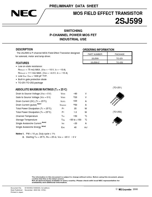
©2000PRELIMINARY DATA SHEETDocument No.D14644EJ1V0DS00 (1st edition)Date Published November 2000 NS CP(K)Printed in JapanThe information in this document is subject to change without notice. Before using this document, please confirm that this is the latest version.Not all devices/types available in every country. Please check with local NEC representative for availability and additional information.DESCRIPTIONThe 2SJ599 is P-channel MOS Field Effect Transistor designed for solenoid, motor and lamp driver.FEATURES•Low on-state resistance:R DS(on)1 = 75 m Ω MAX. (V GS = –10 V, I D = –10 A)R DS(on)2 = 111 m Ω MAX. (V GS = –4.0 V, I D = –10 A)•Low C iss : C iss = 1300 pF TYP.•Built-in gate protection diode •TO-251/TO-252 packageABSOLUTE MAXIMUM RATINGS (T A = 25°C)Drain to Source Voltage (V GS = 0 V)V DSS –60V Gate to Source Voltage (V DS = 0 V)V GSS +20V Drain Current (DC) (T C = 25°C)I D(DC)+20A Drain Current (pulse)Note1I D(pulse)+50A Total Power Dissipation (T C = 25°C)P T 35W Total Power Dissipation(T A = 25°C)P T 1.0W Channel Temperature T ch 150°C Storage Temperature T stg–55 to +150°C Single Avalanche Current Note2I AS –20A Single Avalanche EnergyNote2E AS40mJNotes 1.PW ≤ 10 µs, Duty cycle ≤ 1%2.Starting T ch = 25°C, R G = 25 Ω, V GS = –20 V ¡ 0 VORDERING INFORMATIONPART NUMBERPACKAGE 2SJ599TO-2512SJ599-ZTO-252(TO-251)(TO-252)Preliminary Data Sheet D14644EJ1V0DS2TEST CIRCUIT 1 AVALANCHE CAPABILITYV GS = –20 V DDTEST CIRCUIT 3 GATE CHARGETEST CIRCUIT 2 SWITCHING TIMEV LDDτ = 1s µDuty Cycle ≤ 1%L DD−Preliminary Data Sheet D14644EJ1V0DS3PACKAGE DRAWINGS (Unit : mm)1) TO-251 (MP-3)2) TO-252 (MP-3Z)EQUIVALENT CIRCUITBody DiodeDiodeDrainRemark The diode connected between the gate and source of the transistor serves as a protector against ESD.When this device actually used, an additional protection circuit is externally required if a voltage exceeding the rated voltage may be applied to this device.M8E 00. 4The information in this document is current as of November, 2000. The information is subject to change without notice. For actual design-in, refer to the latest publications of NEC's data sheets or data books, etc., for the most up-to-date specifications of NEC semiconductor products. Not all products and/or types are available in every country. Please check with an NEC sales representative for availability and additional information.No part of this document may be copied or reproduced in any form or by any means without prior written consent of NEC. NEC assumes no responsibility for any errors that may appear in this document.NEC does not assume any liability for infringement of patents, copyrights or other intellectual property rights of third parties by or arising from the use of NEC semiconductor products listed in this document or any other liability arising from the use of such products. No license, express, implied or otherwise, is granted under any patents, copyrights or other intellectual property rights of NEC or others.Descriptions of circuits, software and other related information in this document are provided for illustrative purposes in semiconductor product operation and application examples. The incorporation of these circuits, software and information in the design of customer's equipment shall be done under the full responsibility of customer. NEC assumes no responsibility for any losses incurred by customers or third parties arising from the use of these circuits, software and information.While NEC endeavours to enhance the quality, reliability and safety of NEC semiconductor products, customers agree and acknowledge that the possibility of defects thereof cannot be eliminated entirely. To minimize risks of damage to property or injury (including death) to persons arising from defects in NEC semiconductor products, customers must incorporate sufficient safety measures in their design, such as redundancy, fire-containment, and anti-failure features.NEC semiconductor products are classified into the following three quality grades:"Standard", "Special" and "Specific". The "Specific" quality grade applies only to semiconductor products developed based on a customer-designated "quality assurance program" for a specific application. The recommended applications of a semiconductor product depend on its quality grade, as indicated below. Customers must check the quality grade of each semiconductor product before using it in a particular application."Standard":Computers, office equipment, communications equipment, test and measurement equipment, audioand visual equipment, home electronic appliances, machine tools, personal electronic equipment and industrial robots"Special":Transportation equipment (automobiles, trains, ships, etc.), traffic control systems, anti-disastersystems, anti-crime systems, safety equipment and medical equipment (not specifically designed for life support)"Specific":Aircraft, aerospace equipment, submersible repeaters, nuclear reactor control systems, lifesupport systems and medical equipment for life support, etc.The quality grade of NEC semiconductor products is "Standard" unless otherwise expressly specified in NEC's data sheets or data books, etc. If customers wish to use NEC semiconductor products in applications not intended by NEC, they must contact an NEC sales representative in advance to determine NEC's willingness to support a given application.(Note)(1)"NEC" as used in this statement means NEC Corporation and also includes its majority-owned subsidiaries.(2)"NEC semiconductor products" means any semiconductor product developed or manufactured by or for NEC (as defined above).••••••。
2SK1933中文资料
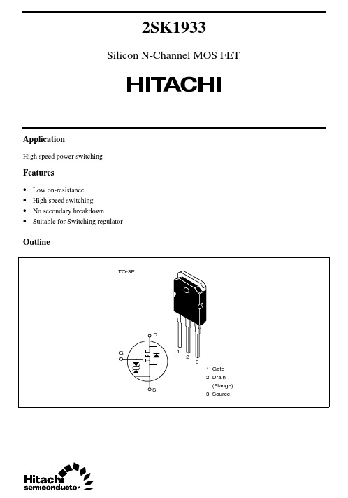
2SK1933Silicon N-Channel MOS FETApplicationHigh speed power switchingFeatures• Low on-resistance• High speed switching• No secondary breakdown• Suitable for Switching regulatorOutline2SK19332Absolute Maximum Ratings (Ta = 25°C)ItemSymbol Ratings Unit Drain to source voltage V DSS 900V Gate to source voltage V GSS ±30V Drain current I D10A Drain peak currentI D(pulse)*130A Body to drain diode reverse drain current I DR 10A Channel dissipation Pch*2150W Channel temperature Tch 150°C Storage temperatureTstg–55 to +150°CNotes 1.PW ≤ 10 µs, duty cycle ≤ 1 %2.Value at Tc = 25°C2SK19333Electrical Characteristics (Ta = 25°C)ItemSymbol Min Typ Max Unit Test conditions Drain to source breakdown voltageV (BR)DSS 900——V I D = 10 mA, V GS = 0Gate to source breakdown voltageV (BR)GSS ±30——V I G = ±100 µA, V DS = 0Gate to source leak current I GSS ——±10µA V GS = ±25 V, V DS = 0Zero gate voltage drain current I DSS——250µA V DS = 720 V, V GS = 0Gate to source cutoff voltage V GS(off) 2.0— 3.0V I D = 1 mA, V DS = 10 V Static drain to source on state resistanceR DS(on)—0.9 1.2ΩI D = 5 A V GS = 10 V*1Forward transfer admittance |y fs | 4.57—S I D = 5 A V DS = 20 V*1Input capacitance Ciss —2620—pF V DS = 10 V Output capacitanceCoss —830—pF V GS = 0Reverse transfer capacitance Crss —320—pF f = 1 MHz Turn-on delay time t d(on)—30—ns I D = 5 A Rise timet r —140—ns V GS = 10 V Turn-off delay time t d(off)—285—ns R L = 6 ΩFall timet f —170—ns Body to drain diode forward voltageV DF —0.9—V I F = 10 A, V GS = 0Body tp drain diode reverse recovery time t rr—1600—nsI F = 10 A, V GS = 0,di F / dt = 100 A / µs Note1.Pulse Test2SK193342SK193352SK193362SK193372SK19338Hitachi CodeJEDECEIAJWeight (reference value)TO-3P—Conforms5.0 gUnit: mmCautions1.Hitachi neither warrants nor grants licenses of any rights of Hitachi’s or any third party’s patent,copyright, trademark, or other intellectual property rights for information contained in this document.Hitachi bears no responsibility for problems that may arise with third party’s rights, includingintellectual property rights, in connection with use of the information contained in this document.2.Products and product specifications may be subject to change without notice. Confirm that you have received the latest product standards or specifications before final design, purchase or use.3.Hitachi makes every attempt to ensure that its products are of high quality and reliability. However,contact Hitachi’s sales office before using the product in an application that demands especially high quality and reliability or where its failure or malfunction may directly threaten human life or cause risk of bodily injury, such as aerospace, aeronautics, nuclear power, combustion control, transportation,traffic, safety equipment or medical equipment for life support.4.Design your application so that the product is used within the ranges guaranteed by Hitachi particularly for maximum rating, operating supply voltage range, heat radiation characteristics, installationconditions and other characteristics. Hitachi bears no responsibility for failure or damage when used beyond the guaranteed ranges. Even within the guaranteed ranges, consider normally foreseeable failure rates or failure modes in semiconductor devices and employ systemic measures such as fail-safes, so that the equipment incorporating Hitachi product does not cause bodily injury, fire or other consequential damage due to operation of the Hitachi product.5.This product is not designed to be radiation resistant.6.No one is permitted to reproduce or duplicate, in any form, the whole or part of this document without written approval from Hitachi.7.Contact Hitachi’s sales office for any questions regarding this document or Hitachi semiconductor products.Hitachi, Ltd.Semiconductor & Integrated Circuits.Nippon Bldg., 2-6-2, Ohte-machi, Chiyoda-ku, Tokyo 100-0004, Japan Tel: Tokyo (03) 3270-2111 Fax: (03) 3270-5109Copyright ' Hitachi, Ltd., 1999. All rights reserved. Printed in Japan.Hitachi Asia Pte. Ltd.16 Collyer Quay #20-00Hitachi TowerSingapore 049318Tel: 535-2100Fax: 535-1533URLNorthAmerica : http:/Europe : /hel/ecg Asia (Singapore): .sg/grp3/sicd/index.htm Asia (Taiwan): /E/Product/SICD_Frame.htm Asia (HongKong): /eng/bo/grp3/index.htm Japan : http://www.hitachi.co.jp/Sicd/indx.htmHitachi Asia Ltd.Taipei Branch Office3F, Hung Kuo Building. No.167, Tun-Hwa North Road, Taipei (105)Tel: <886> (2) 2718-3666Fax: <886> (2) 2718-8180Hitachi Asia (Hong Kong) Ltd.Group III (Electronic Components)7/F., North Tower, World Finance Centre,Harbour City, Canton Road, Tsim Sha Tsui,Kowloon, Hong Kong Tel: <852> (2) 735 9218Fax: <852> (2) 730 0281 Telex: 40815 HITEC HXHitachi Europe Ltd.Electronic Components Group.Whitebrook ParkLower Cookham Road MaidenheadBerkshire SL6 8YA, United Kingdom Tel: <44> (1628) 585000Fax: <44> (1628) 778322Hitachi Europe GmbHElectronic components Group Dornacher Stra§e 3D-85622 Feldkirchen, Munich GermanyTel: <49> (89) 9 9180-0Fax: <49> (89) 9 29 30 00Hitachi Semiconductor (America) Inc.179 East Tasman Drive,San Jose,CA 95134 Tel: <1> (408) 433-1990Fax: <1>(408) 433-0223For further information write to:。
SN74HC594中文资料

元器件交易网IMPORTANT NOTICETexas Instruments (TI) reserves the right to make changes to its products or to discontinue any semiconductorproduct or service without notice, and advises its customers to obtain the latest version of relevant informationto verify, before placing orders, that the information being relied on is current.TI warrants performance of its semiconductor products and related software to the specifications applicable atthe time of sale in accordance with TI’s standard warranty. Testing and other quality control techniques areutilized to the extent TI deems necessary to support this warranty. Specific testing of all parameters of eachdevice is not necessarily performed, except those mandated by government requirements.Certain applications using semiconductor products may involve potential risks of death, personal injury, orsevere property or environmental damage (“Critical Applications”).TI SEMICONDUCTOR PRODUCTS ARE NOT DESIGNED, INTENDED, AUTHORIZED, OR WARRANTEDTO BE SUITABLE FOR USE IN LIFE-SUPPORT APPLICATIONS, DEVICES OR SYSTEMS OR OTHERCRITICAL APPLICATIONS.Inclusion of TI products in such applications is understood to be fully at the risk of the customer. Use of TIproducts in such applications requires the written approval of an appropriate TI officer. Questions concerningpotential risk applications should be directed to TI through a local SC sales office.In order to minimize risks associated with the customer’s applications, adequate design and operatingsafeguards should be provided by the customer to minimize inherent or procedural hazards.TI assumes no liability for applications assistance, customer product design, software performance, orinfringement of patents or services described herein. Nor does TI warrant or represent that any license, eitherexpress or implied, is granted under any patent right, copyright, mask work right, or other intellectual propertyright of TI covering or relating to any combination, machine, or process in which such semiconductor productsor services might be or are used.Copyright © 1998, Texas Instruments Incorporated。
S594TRW中文资料
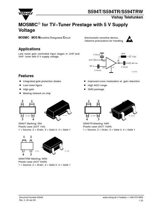
2
1
1
2
94 9279
13 579
94 9278
95 10831
3
4
4
3
S594T Marking: 594 Plastic case (SOT 143) 1 = Source, 2 = Drain, 3 = Gate 2, 4 = Gate 1
S594TR Marking: 94R Plastic case (SOT 143R) 1 = Source, 2 = Drain, 3 = Gate 2, 4 = Gate 1
元器件交易网
S594T/S594TR/S594TRW
Vishay Telefunken Absolute Maximum Ratings
Tamb = 25_C, unless otherwise specified Parameter Drain - source voltage Drain current Gate 1/Gate 2 - source peak current Gate 1/Gate 2 - source voltage Total power dissipation Channel temperature Storage temperature range Test Conditions Symbol Value VDS 8 ID 20 ±IG1/G2SM 10 ±VG1/G2SM 6 Ptot 160 TCh 150 Tstg –55 to +150 Unit V mA mA V mW °C °C
Electrical DC Characteristics
Tamb = 25_C, unless otherwise specified Parameter Gate 1 - source breakdown voltage Gate 2 - source breakdown voltage Gate 1 - source leakage current Gate 2 - source leakage current Drain current Self-biased operating current Gate 2 - source cut-off voltage Test Conditions ±IG1S = 10 mA, VG2S = VDS = 0 ±IG2S = 10 mA, VG1S = VDS = 0 +VG1S = 5 V, VG2S = VDS = 0 –VG1S = 5 V, VG2S = VDS = 0 ±VG2S = 5 V, VG1S = VDS = 0 VDS = 5 V, VG1S = 0, VG2S = 4 V VDS = 5 V, VG1S = nc, VG2S = 4 V VDS = 5 V, VG1S = nc, ID = 20 mA Symbol Min ±V(BR)G1SS 7 ±V(BR)G2SS +IG1SS –IG1SS ±IG2SS IDSS IDSP VG2S(OFF) 50 7 7 Typ Max Unit 10 V 10 50 100 20 500 14 V
HSJ450中文资料
3.4
29
14
19
11
19
150
5.1
41
20
27
16
22
175
8.0
60
29
40
23
24
200
14
92
44
61
35
26
225
14
110
53
73
42
30
250
16
130
62
86
49
36
300
26
200
96
132
76
38
350
37
290
139
191
110
40
400
63
450
216
297
171
42
450
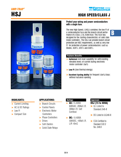
Features/Benefits ® Optimized over-load capability for withstanding
elevated levels of current during electronic motor controller starts
® Low I2t (low thermal energy)
OUTLINE FIG.
2 2 2 2 2 2 2 2 2 2 2 2 2
Recommended Fuse Blocks with Box Connectors for AMP-TRAP Class J Fuses
Fuse Catalog Number Ampere 600V or Less Rating 1 Pole 3 Pole 0-30 US3J1I US3J3I 31-60 US6J1I US6J3I 61-100 61036J 61038J 101-200 621001J 62003J 201-400 64031J 64033J 401-600 6631J 6633J
2SJ352中文资料

2SJ352中⽂资料2SJ351, 2SJ352Silicon P-Channel MOS FETADE-208-1431st. EditionApplicationLow frequency power amplifierComplementary pair with 2SK2220, 2SK2221FeaturesHigh power gainExcellent frequency responseHigh speed switchingWide area of safe operationEnhancement-modeGood complementary characteristicsEquipped with gate protection diodesOrdering InformationType No.VDSX2SJ351–180 V2SJ352–200 V2SJ351, 2SJ3522OutlineAbsolute Maximum Ratings (Ta = 25°C)ItemSymbol Ratings Unit Drain to source voltage 2SJ351V DSX–180V2SJ352–200Gate to source voltage V GSS ±20V Drain currentI D –8A Body to drain diode reverse drain current I DR –8A Channel dissipation Pch*1100W Channel temperature Tch 150°C Storage temperature Tstg –55 to +150°C Note:1.Value at T C = 25°C2SJ351, 2SJ3523Electrical Characteristics (Ta = 25°C)ItemSymbol Min Typ Max Unit Test conditions Drain to source 2SJ351V (BR)DSX–180——VI D = –10 mA, V GS = 10 Vbreakdown voltage2SJ352–200——Gate to source breakdown voltageV (BR)GSS ±20——V I G = ±100 µA, V DS = 0Gate to source cutoff voltage V GS(off)–0.15—–1.45V I D = –100 mA, V DS =–10 V Drain to source saturation voltageV DS(sat)——–12V I D = –8 A, V GD = 0*1Forward transfer admittance |y fs |0.7 1.0 1.4S I D = –3 A, V DS = –10 V*1Input capacitance Ciss —800—pF V GS = 5 V, V DS = –10 V,Output capacitanceCoss —1000—pF f = 1 MHzReverse transfer capacitance Crss —18—pF Turn-on time t on —320—ns V DD = –30 V, I D = –4 A Turn-off time t off—120—nsNote:1.Pulse test2SJ351, 2SJ35242SJ351, 2SJ3526Hitachi CodeJEDECEIAJWeight (reference value)TO-3P—Conforms5.0 gUnit: mmCautions1.Hitachi neither warrants nor grants licenses of any rights of Hitachi’s or any third party’s patent,copyright, trademark, or other intellectual property rights for information contained in this document.Hitachi bears no responsibility for problems that may arise with third party’s rights, includingintellectual property rights, in connection with use of the information contained in this document.2.Products and product specifications may be subject to change without notice. Confirm that you have received the latest product standards or specifications before final design, purchase or use.3.Hitachi makes every attempt to ensure that its products are of high quality and reliability. However,contact Hitachi’s sales office before using the product in an application that demands especially high quality and reliability or where its failure or malfunction may directly threaten human life or cause risk of bodily injury, such as aerospace, aeronautics, nuclear power, combustion control, transportation,traffic, safety equipment or medical equipment for life support.4.Design your application so that the product is used within the ranges guaranteed by Hitachi particularly for maximum rating, operating supply voltage range, heat radiation characteristics, installationconditions and other characteristics. Hitachi bears no responsibility for failure or damage when used beyond the guaranteed ranges. Even within the guaranteed ranges, consider normally foreseeable failure rates or failure modes in semiconductor devices and employ systemic measures such as fail-safes, so that the equipment incorporating Hitachi product does not cause bodily injury, fire or other consequential damage due to operation of the Hitachi product.5.This product is not designed to be radiation resistant.6.No one is permitted to reproduce or duplicate, in any form, the whole or part of this document without written approval from Hitachi.7.Contact Hitachi’s sales office for any questions regarding this document or Hitachi semiconductor products.Hitachi, Ltd.Semiconductor & Integrated Circuits.Nippon Bldg., 2-6-2, Ohte-machi, Chiyoda-ku, Tokyo 100-0004, Japan Tel: Tokyo (03) 3270-2111 Fax: (03) 3270-5109 Copyright ' Hitachi, Ltd., 1999. All rights reserved. Printed in Japan.Hitachi Asia Pte. Ltd.16 Collyer Quay #20-00Hitachi TowerSingapore 049318Tel: 535-2100Fax: 535-1533URLNorthAmerica : http:/doc/bfe7be20915f804d2b16c12b.html /Europe :/doc/bfe7be20915f804d2b16c12b.html /hel/ecg Asia (Singapore):/doc/bfe7be20915f804d2b16c12b.html .sg/grp3/sicd/index.htm Asia (Taiwan):/doc/bfe7be20915f804d2b16c12b.html /E/Product/SICD_Frame.htm Asia (HongKong):/doc/bfe7be20915f804d2b16c12b.html /eng/bo/grp3/index.htm Japan :http://www.hitachi.co.jp/Sicd/indx.htmHitachi Asia Ltd.Taipei Branch Office3F, Hung Kuo Building. No.167, Tun-Hwa North Road, Taipei (105)Tel: <886> (2) 2718-3666Fax: <886> (2) 2718-8180 Hitachi Asia (Hong Kong) Ltd.Group III (Electronic Components)7/F., North Tower, World Finance Centre,Harbour City, Canton Road, Tsim Sha Tsui,Kowloon, Hong Kong Tel: <852> (2) 735 9218Fax: <852> (2) 730 0281 Telex: 40815 HITEC HXHitachi Europe Ltd.Electronic Components Group.Whitebrook ParkLower Cookham Road MaidenheadBerkshire SL6 8YA, United Kingdom Tel: <44> (1628) 585000Fax: <44> (1628) 778322Hitachi Europe GmbHElectronic components Group Dornacher Stra§e 3D-85622 Feldkirchen, Munich GermanyTel: <49> (89) 9 9180-0Fax: <49> (89) 9 29 30 00Hitachi Semiconductor (America) Inc.179 East Tasman Drive,San Jose,CA 95134 Tel: <1> (408) 433-1990Fax: <1>(408) 433-0223For further information write to:。
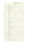
2SA系列(PNP型)三极管全参数表
-50 200M 100-320 3CK14H
-50 200M 100-320 3CK14H
-30 200M 100-500 3CG120A
-30 200M 100-500 3CK14F
-30 200M 100-500 3CK14F
-50 200M 100-320 3CG120B
-50 200M 100-320 3CK14H
-50 200M 100-320 3CK14H
-30 280M
3CG120A
-35 200M 180-700 3CG110C
-55 200M 180-700 3CG170A
-32 200M 82-390
-50 140M 120-560
实用标准文档
2SA1037B
LRC
2SA1037K
ROHM
2SA1038S 2SA1039
配对管 2SC1383
-25 200M 50-340
CK77A
2SA0684
PANASONIC 硅 PNP 三极管,低频功率放大和驱动, 1 -1.5 -60
配对管 2SC1384
-50 200M 50-340
CK77A
2SA0794
PANASONIC 硅 PNP 三极管,低频功率放大和驱动, 1.2
实用标准文档
型号
厂商
特性用途
集电极 集电极
集电极-基 集电极-发
最大直 最大允
特征频
极击穿电 射极击穿
流耗散 许直流
率
压
电压
功率 电流
ft(Hz)
BVcbo(V) BVceo(V)
Pcm(W) Icm(A)
放大倍数
国内外代换 型号
胶带输送机“九大保护”安装标准

超温自动洒水:热电偶式传感器固 定在主传动滚筒瓦座上,传感器与 主传动滚筒距离为10至15mm;采 用红外线传感器时,传感器发射孔
应正对主传动滚筒进行检测,距离 滚筒300mm~500mm。
m `
m`
沿线急停保护:输送机巷道内每隔100m 安装一个,装载点、人行过桥处、机头、 机尾均应设有急停开关,开关信号要接入 带式输送机控制系统,并能自锁和复位具 备双闭锁功能。
6
四、超温自动洒水
1、保护定义:在测温点处,温度超过规定时自动洒水装置
能自动启动洒水装置,喷水降温。 2、安装标准:1、安装在下风流的驱动滚筒与张紧改向滚筒 之间,沿驱动滚筒轴向平行布置,滚筒轴向喷洒范围应全部 覆盖,距滚筒表面300㎜处。2、超温洒水喷嘴安装的喷洒方 向,在带面与驱动滚筒的脱离点至滚筒水平中心线之间。3、 温度保护的安装位置必须与超温洒水装置电磁阀动作设定的 温度值匹配。4、每一个驱动滚筒处至少安装一个与温度保 护匹配的超温洒水装置。 3、工作原理:当温度超过规定时,超温洒水装置应报警, 同时起动洒水装置喷水降温,洒水时能起到对驱动胶带和驱 动滚筒同时灭火降温的效果,其水源的阀门应是常开。
垂直吊挂于胶带机头驱动滚筒下风侧10至15m处的输送机机正上方,距顶板不大于300mm。当输送机为多滚筒 驱动时,应以靠近机头处主滚筒为准,当连续2秒内烟雾浓度达到1.5倍时,烟雾保护报警并中止带式输送机运行, 同时起动洒水装置喷水降温(G2B51145-2015-15.3.6)。
带式输送机保护安装要求
2、胶带输送机九大保护按照功能分为两大类: ⑴机械式:堆煤保护、防跑偏保护、沿线急停保护、温度保护、防撕裂保护、张紧力下 降保护。 ⑵感应式:滑保护、超温自动洒水装置、烟雾保护。
AVTM56-9J复杂版A的超声波电闸和漏气探测器说明书

1981Instruction ManualAVTM56-9J Rev. AFor theUltrasonic Coronaand Leak DetectorCatalog Number 569001and AccessoriesThe industry leader since 1895, AVO Biddle Instruments offers a comprehensive line of electrical test and measurement products, from portable instruments for use in the field to fully-integrated systems for high voltage systems testing. AVO Biddle Instruments fulfills a range of requirements found in electric utility, large industrial, electrical apparatus manufacturing, military and governmental applications worldwide.Portable Field Test EquipmentAVO Biddle’s extensive product line includes its well known portable field test equipment, including the MEGGER® family of Insulation Resistance testers, which indicate the deterioration of electrical insulation; Ground Resistance Testers for installing and maintaining grounding systems; and equipment for locating faults in both power and communications cable.Precision Test & Measurement EquipmentAVO Biddle operates a calibration lab traceable to the NIST to insure the quality of its precision products, which includes the DRLO® line of digital low resistance ohmmeters.High Voltage Systems Test EquipmentAVO Biddle is a leading supplier of equipment and systems for High Voltage Systems testing applications, from rigorous QC testing of manufactured power cable to demanding R&D requirements in the Aerospace industry. This range of products includes fully-integrated systems for detecting minute levels of partial discharge to HV power supplies and DC dielectric, transformer turn ratio and capacitance/dissipation factor test sets for use in the field testing of large power apparatus.No matter whether it’s a hand-held MEGGER® Insulation Tester or a 750kV Partial Discharge Detection Systems, AVO Biddle Instruments backs it up with a full range of support services:Application AssistanceOur Application Engineers can demonstrate how AVO International can fulfill your testing requirements.Customer ServiceContact one of AVO’s Customer Service Representatives for quick answers to your questions regarding where to buy, order entry, delivery or warranty and repair information. They can also assist you in ordering replacement parts, accessories, operating/service manuals and product/application literature.Worldwide Network of Authorized Stocking DistributorsMany of our products are readily available through an Authorized Stocking Distributor near you.And More…AVO Biddle also supports you with expert calibration services traceable to the NIST, full one-year warranty, convenient leasing and much more. Because when you buy AVO Biddle, you’re getting more than a quality product.To speak to an AVO International Customer Service Representative or for information about any of Biddle’s products and services, contact us at:P.O. Box 9007Valley Forge, PA 19485-10071-800-723-2861 ext. 8578610-676-8578Shipping Address:Valley Forge Corporate Center2621 Van Buren AvenueNorristown, PA 19403Instruction Manual 56-9Jfor the use of ULTRASONIC CORONAand LEAK DETECTORCatalog Number 569001AVO InternationalP.O. Box 9007 Valley Forge, PA 19485-1007TABLE OF CONTENTSFIG. 1: ULTRASONIC CORONA AND LEAK DETECTOR CAT. NO. 569001..a1 FIG. 2: ACCESSORY ITEMS............................................................................a2 INTRODUCTION...............................................................................................A1 SAFETY PRECAUTIONS..................................................................................B1 RECEIVING INSTRUCTIONS...........................................................................C1 DESCRIPTION AND SPECIFICATIONS...........................................................D1 OPERATION......................................................................................................E1 APPLICATION....................................................................................................F1 MAINTENANCE.................................................................................................G1 WARRANTY AND REPAIRS.............................................................................H1a1FIGURE 1: ULTRASONIC CORONA AND LEAK DETECTOR CATALOG NO. 569001Contact Probe, Catalog No. 569001-8 UltrasonicTone Generator,Catalog No.569001-7FIGURE 2: ACCESSORY ITEMS.a2INTRODUCTIONElectrical discharges from a high voltage terminal to the air (corona) or along an insulated surface generate acoustical signals. Over a wide range of circumstances a significant portion of the generated signal energy will have frequencies above the range of the human ear. This is the ultrasonic frequency range and may be used to detect the presence of corona or surface discharge with the advantage that audible background noise is excluded.Corona and surface discharge are localized to small areas relative to the total size of the equipment. The Biddle Cat. No. 569001 Ultrasonic Corona and Leak Detector is equipped with a highly directional horn to permit the user to localize the source of the electrical discharge while remaining at a safe distance from the electrical terminals. This directional property also increases the sensitivity of the detector and tends to exclude any ultrasonic signals not related to the test in progress. The Cat. No. 569001 is effective in locating corona on insulators, bushings, and potheads in energized circuits such as utility poles, non-enclosed switchgear, bus bars or transformers and aids in isolating multiple sources located on the equipment under test. It is also useful in checking insulation test setups for either ac or dc to determine if corona is present on the test terminals. Pinpointing such corona and demonstrating its reduction will usually result in considerable saving of testing time and assist in obtaining reliable results.The Detector is designed for easy use. It is supplied in a compact light-weight carrying case; it operates on a single transistor battery and is quickly ready for service in the field or on the test floor.In addition to detecting corona sources, the Detector is an excellent tool for locating gas leaks and other sources of ultrasound.A1INTRODUCTION (Cont’d.)When ultrasound is generated in parts of a container or assembly, the surfaces of the container usually transmit the ultrasonic sound but may not radiate effectively. For such cases the Cat. No. 569001-8 Contact Probe accessory is available. This probe makes direct contact with the surface to detect the ultrasound, similar to the action of a stethoscope. The contact probe is used to identify such problems as defective bearings or gears, or leaking steam traps. Ultrasonics can also be used to detect leaks in a sealed container before it is filled. (This can be a significant cost saving.) The container can be considered, in the general sense, as any enclosure where a leak may be damaging. For such applications, the Cat. No. 569001-7 Ultrasonic Transmitter is available. In effect, the transmitter is sealed in the enclosure or container while it is transmitting. Since ultrasonic sound will escape through remarkably small openings, the detector is used to scan the outside to locate the leak.A2Section BSAFETY PRECAUTIONSSAFETY IS THE RESPONSIBILITY OF THE USERLA SEGURIDAD ES LA RESPONSABILIDAD DEL OPERADOR Although this test set does not contain any high voltages, it is usually operated in the vicinity of high voltage apparatus. The Test Set must be used only by persons fully aware of the proper safety procedure in such locations.Further precautions are necessary because the person wearing headphones may not hear vehicular traffic or audible alarms. When such hazards exist BIDDLE Instruments recommends that the loudspeaker or meter of the Cat. No. 569001 be used in preference to the headphones.The sound produced by the headphones of the Cat. No. 569001 can reach levels approaching those that risk hearing damage, therefore, the operator must set the volume control at a sufficiently low level to prevent discomfort.BIDDLE Instruments considers it advisable for the user to become familiar with the Cat. No. 569001 prior to using it in the field.Section CRECEIVING INSTRUCTIONSWhen your BIDDLE instrument arrives, check the equipment received against the packing list to ensure that all items are present. Notify AVO International Valley Forge, PA 19485 of any shortage. Make sure all the components shown in Figure 1 are included.Examine the instrument for damage received in transit. If any damage is discovered, file a claim with the carrier at once and notify BIDDLE Instruments or its nearest authorized sales representative, giving detailed description of the damage observed.This instrument has been thoroughly tested and inspected to meet rigid inspection specifications before being shipped. It is ready for use when set up as indicated in Section E.DESCRIPTION and SPECIFICATIONSGENERALThe Biddle Cat. No. 569001 Detector consists of several interconnecting components supplied in a cushioned carrying case as shown in Figure 1. The microphone probe and the receiver make up a basic complete system. The receiver converts and amplifies the ultrasonic signals from the microphone probe to an audible loudspeaker or headphone output and also to a meter deflection. It has a single control for on-off and volume.Although the microphone probe has directional properties, a great improvement is provided by assembling it into the directional “horn” which is the key part of the system. The horn focuses sharply enough to enable the user to locate corona sources while remaining at a safe distance from the high-voltage energized apparatus. A pistol-grip holder and a peepsight provide for aiming.A rubber “sound concentrator” tube can also be attached to the microphone; this aids in locating very small ultrasound emitters of mechanical nature such as pinhole gas leaks.Two accessories are available for use with the basic detector, (see Fig. a2). One is a contact probe that replaces the microphone. When this is used, the detector acts similar to a stethoscope to detect ultrasound transmitted in solid bodies. The second accessory is an ultrasound Tone Generator; an independent unit that can be placed in an enclosure. The ultrasound generated will penetrate small openings and can be detected using the microphone pickup with the detector. CIRCUIT DESCRIPTIONThe solid state circuit operates on the hetrodyne (heat frequency) principle. The detecting microphone probe is crystal responsive to frequencies from about 35 to 45 kilohertz.The receiving circuitry amplifies the transducer probe signal and mixes it with a signal from a fixed-frequency local oscillator to produce a beat note of about 1000 Hz when the microphone is responding to a signal of 40 kilohertz. The amplified beat frequency is used to drive the internal speaker and also rectified to operate the output meter. Plugging the headphones into the circuit diverts the signal from the speaker to the headphones.DESCRIPTION AND SPECIFICATIONS (Cont’d.)The circuit is powered from a 9-volt transistor type battery. The power requirements are small enough so that the battery life is on the order of 75 hours if used intermittently.The circuit has sufficient gain available so that the sensitivity is limited only by the noise of the input stage.SPECIFICATIONS:Operating frequency .......................range35 to 45 kHz Directivity.........................................Distinguishes point sources6 inches apart at 5 feet and1 foot apart at 10 feet. Output..............................................Headphones, speaker and meter. Sensitivity.........................................Can detect corona sources inair with as little as 5 micro-coulombsat 5 feet.Power Supply...................................9-volt transistor battery,NEDA #1604, Burgess #2V6,Eveready #216 or equivalent.Components included:Padded carrying case, receiver with meter and speaker, muff-type headphones with 12 ft. retractile cord, microphone probe with 5½ ft. retractile cord, directional horn with peep-sight and pistol-grip holder, rubber sound concentrator. PHYSICAL Dimensions......................................17 x 12 x 5 inches,(432 x 305 x 127 mm) Weight..............................................5½ lbs. (2.5Kg.)DESCRIPTION AND SPECIFICATIONS (Cont’d.)ENVI RONMENTALTemperature range..........................32ºF to 110ºF (0º to 43ºC)The instrument must be protected from direct exposure to water. It can withstand the shock and vibration normally encountered in field use.Catalog No. 569001-8 Contact Probe: Responds at 40kHz to minutedisplacements in solid bodies. Overall Length.................................10 inches (25.4 cm). Diameter..........................................1 3/4 inches (4.4 cm).Probe Stem Length..........................6 inches (15.2 cm).Probe Diameter ...............................1/8 inch (.32 cm).Catalog No. 569001-7 Ultrasonic Tone Generator (Self-Contained)Overall Size.....................................3½ x 2½ x 1 3/4 inches(8.9 x 5.7x 4.4 cm). Controls...........................................On-Off Toggle Switch.Power Supply...................................9-Volt transistor battery;NEDA 1604. Burgess 2V6, Eveready216.or equivalent.Operating Frequency.......................Centered on 40kHz.OPERATIONPRELIIMINARYSelect any accessories to be used with the basic system (microphone probe and receiver). Fit the microphone with either the sound concentrator or the directional horn by sliding it into the mating opening. In the case of the horn, the microphone must be fully inserted into the socket and the two thumb screws tightened with the fingers to prevent the microphone from dropping out if the horn is pointed overhead. Now clip the receiver to a convenient article of clothing or hold it in your hand. Connect the microphone probe cord to the fitting marked “PROBE’ making sure to tighten the lock ring.If the headphones are to be used they are simply plugged into the jack marked “PHONE”. Turn on the set by pushing the control thumb wheel to the left. Increase the volume setting until the background noise is heard. Hold your hand about an inch or two from the horn mouth (probe mouth) and lightly rub your fingers together. This will produce a distinct output to insure that everything is operating. Now turn the receiver off.LOCATING CORONA SOURCESMake a careful survey of the apparatus to be tested and take all precautions to avoid electrical shock. Identify the high voltage terminals and suspected regions to be examined. Choose a safe location that gives a clear direct air path to the suspected area.WARNING!DO NOT APPROACH ENERGIZED APPARATUS WITH THEHORN IN HAND: IT IS AN EXCELLENT ELECTRICALCONDUCTOR!Turn on the receiver and scan the suspected area with the microphone probe by simply pointing it at the suspected regions.Corona, surface discharge or arcing will be readily identified over the background noise. If the circuit is ac the corona will be identified as a very rough sounding tone with the power frequency identifiable. The sound is similar to that produced by passing a coarse file over the edge of a 3 x 5 paper card.OPERATION (Cont’d.)If the apparatus is operating with dc, you will hear a series of popping sounds when there is an intermittent discharge. For extensive discharges the sound approaches a tone.CONTACT PROBETo use the Contact Probe, connect it to the receiver in place of the microphone. Test the system just as for the microphone except lightly rub your finger on the probe stem.WARNING!THE CONTACT PROBE IS NOT INTENDED TO PROVIDEHIGH VOLTAGE INSULATION. IT SHOULD ONLY BE USEDWHERE NO DANGER OF ELECTRIC SHOCK EXISTS.TONE GENERATORTo use the Tone Generator, move the toggle switch to the “On” position. To insure that the Tone Generator is operating, place it at least 5 feet away and listen for a tone, using the receiver with the microphone. Be sure to keep the gain setting low to avoid discomfort.Section FAPPLICATIONThe Corona and Leak Detector can be adapted to many different situations.In the case of large apparatus such as a small open air substation or a portion of a larger substation, use the microphone probe without the directional horn when making a fast general survey. To localize a source such as a particular bushing, insulator or cable pothead, use the directional horn and scan the area by aiming directly at the suspected object using the peep sight for accuracy.To investigate the interior of metal-clad switchgear, use the rubber sound concentrator and listen at openings in the structure such as door seams or ventilating openings.The Detector is useful for many other purposes beside the location of electrical discharges. The most common of such uses are:Locating leaks in pressurized communication cable.Locating leaks in air systems.Detecting the flow of water in pipes.Locating leaks in steam lines or steam traps.Detecting poor bearings on rotating machinery.Detecting defective gears.The operation of the Detector is the same as for corona detection; however, since there is no high-voltage hazard, the directional horn may be required to pinpoint the source of ultrasound if the source is not easily accessible. The rubber sound concentrator is useful to pinpoint small leaks. Slide it along the suspect surface to find the maximum signal point.Section GMAINTENANCEThe BIDDLE Cat. No. 569001 Detector requires no routine maintenance except to periodically replace the battery and examine the leads from the microphone probe and headphones. It is recommended that the receiver case, headphones and microphone occasionally be wiped clean with a dry cloth.Turn the receiver off when replacing the battery (located beneath the snap-flap on the leather case).TROUBLESHOOTING and REPAIRIn the event the Detector does not work, first try replacing the battery. If this does not solve the problem, localize the trouble by disconnecting the microphone probe and headphones and turn the receiver on. Set the volume control up to almost full; if the receiver is operating a characteristic background noise will be heard on the speaker and the meter will read. To check the headphones use an ohmmeter at the plug, checking between the metal closest to the shell and (a) the insulated ring, and (b), the tip. Each should measure about 10 ohms.To check the microphone probe, connect it to a test set that is known to be operating. Do not make an ohmmeter measurement of the microphone as this may damage it.Before returning a set for repair make certain that the battery is not at fault. Headphones and microphone probe can be replaced without returning the test set.PARTS LISTThe following parts are available from AVO International for use on the Corona and Leak Detector:NUMBERITEM PARTReceiver 569001-1Carrying Case 569001-5-3Headphones 569001Microphone Probe 569001-2Directional Horn 569001-6Sound Concentrator 569001-4Instruction Manual 56-9JThe Accessory Items 569001-7 and 569001-8 must be replaced as a unit if defective.Section HWARRANTY AND REPAIRSWARRANTYAll products supplied by AVO BIDDLE Instruments are warranted against all defects in material and workmanship for a period of one year following shipment. Our liability is specifically limited to replacing or repairing, at our option, defective equipment. Equipment returned to the factory for repair will be shipped Prepaid and Insured. The warranty does not include batteries, lamps, or tubes, where the original manufacturer’s warranty shall apply. WE MAKE NO OTHER WARRANTY.The warranty is void in the event of abuse or failure by the customer to perform specified maintenance as indicated in the manual.REPAIRSAVO BIDDLE Instruments maintains a complete instrument repair service. Should this instrument ever require repairs we recommend that it be returned to the factory for repair by our instrument specialists. When returning instruments for repairs, either in or out of warranty, they should be shipped Prepaid and Insured, and marked for the attention of the Instrument Service Manager.Printed in the U.S.A.。
J599系列Ⅱ使用说明书

J599系列Ⅱ小圆形电连接器产品使用说明书贵州航天电器股份2006年11月17日J599系列Ⅱ小圆形电连接器产品使用说明书1 概述J599系列小圆形电连接器〔以下简称连接器〕满足GJB 599A—93《耐环境快速别离高密度小圆形电连接器总标准》〔等效美标MIL—DTL—38999〕的要求。
本系列产品主要采用压接端接形式。
连接器接触件采用先进的、可靠性高的压接端接方式,可用装卸工具装入绝缘安装板或从绝缘安装板中卸出,使用和维修方便。
1.1 适用范围J599系列连接器具有技术含量高、品种规格齐全、结构紧凑、体积小、重量轻、接触件密度高、可靠性高、抗振动冲击、耐湿、耐热、耐腐蚀及抗干扰等特点,可以满足用户的多种需求。
可广泛用于航空、航天、电子、船舶、卫星、兵器、信息产业等各个领域中,用于各类信号传输、设备间的电连通等。
1.2 产品分类J599系列Ⅱ产品,其结构为卡口连接结构。
1.3系列Ⅱ连接器的型号命名和接点排列JY 27473 T 12 F 08 P N主键/键槽定位:N、A、B、C、D接触件类别:P 插针、S 插孔绝缘安装板孔位排列外表处理:F、B壳体号:08、10、12、14、16、18、20、22、24类别:T、E壳体型别:27472、27473、27474、27484、2749724513、27508主称代号2 结构特征系列Ⅱ产品主要对接互配的尺寸按照GJB599A系列Ⅱ产品进行设计。
系列Ⅱ产品的主要特点如下:a〕插头座采用卡口连接对接锁紧的形式;b〕插头座尾端带有标准附件接口;c〕插头座通过五个键与槽到达防错插要求;d〕插针基座合件带有界面密封凸台,对接时保证接触件密封;e〕插座端带有周边密封圈,进行产品对接密封。
产品插头由外壳合件(包括外壳、弹性垫圈、挡圈)、基座合件(包括上基座、下基座、封线体、撑簧圈)、塑料环、接触件组成。
具体结构如图1所示。
产品插座由外壳合件〔包括外壳、周边密封圈〕、基座合件(包括上基座、下基座、封线体、撑簧圈、界面密封垫)、塑料环、接触件组成。
电子保护铣电路抵抗筒PDG23N0225D2WJ商品说明书
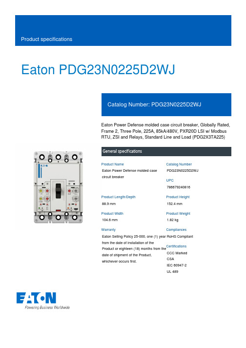
Eaton PDG23N0225D2WJEaton Power Defense molded case circuit breaker, Globally Rated, Frame 2, Three Pole, 225A, 85kA/480V, PXR20D LSI w/ Modbus RTU, ZSI and Relays, Standard Line and Load (PDG2X3TA225)General specificationsEaton Power Defense molded case circuit breakerPDG23N0225D2WJ 78667924081688.9 mm 152.4 mm 104.6 mm 1.82 kg Eaton Selling Policy 25-000, one (1) year from the date of installation of theProduct or eighteen (18) months from thedate of shipment of the Product,whichever occurs first.RoHS Compliant CCC MarkedCSAIEC 60947-2UL 489Product NameCatalog Number UPCProduct Length/Depth Product Height Product Width Product Weight WarrantyCompliancesCertifications225 AComplete breaker 2Three-polePD2 Global Class A PXR 20D LSIModbus RTU600 Vac600 VStandard Line and Load85 kAIC at 480 Vac 150 kAIC @240V (UL)70 kAIC Icu/ 50 kAIC Ics/ 154 kAIC Icm @440V (IEC) 22 kAIC Icu @250 Vdc150 kAIC Icu/ 100 kAIC Ics/ 330 kAIC Icm @240V (IEC) 30/25 kAIC Icu/ 15/13 kAIC Ics @525V South Africa (IEC) 85 kAIC @480V (UL) 30/25 kAIC @600V (UL/CSA)65 kAIC Icu/ 40 kAIC Ics/ 143 kAIC Icm @480V Brazil (IEC) 10 kAIC Icu/ 5 kAIC Ics/ 21 kAIC Icm @690V (IEC) 22 kAIC Icu @125 Vdc70 kAIC Icu/ 70 kAIC Ics/ 154 kAIC Icm @380-415V (IEC)Eaton Power Defense MCCB PDG23N0225D2WJ 3D drawing Amperage Rating Circuit breaker frame type Frame Number of poles Circuit breaker type Class Trip Type Communication Voltage rating Voltage rating - max TerminalsInterrupt rating Interrupt rating range 3D CAD drawing packageApplication notesPower Xpert Protection Manager x32Consulting application guide - molded case circuit breakersPower Xpert Protection Manager x64BrochuresPower Defense brochurePower Defense molded case circuit breaker selection posterPower Defense technical selling bookletPower Defense molded case circuit breakers - Frame 2 product aidCatalogsMolded case circuit breakers catalogPower Xpert Release trip units for Power Defense molded case circuit breakersCertification reportsEU Declaration of Conformity - Power Defense molded case circuit breakersPDG4 CB reportPDG4 CCC certificationPower Defense Declaration concerning California’s Proposition 65PDG2 CB reportInstallation instructionsPower Defense Frame 2 global terminal shield, 3 pole - IL012330EN Power Defense Frame 2 locking devices and handle block instructions - IL012149ENPower Defense Frame 2 multi wire connector kit -PDG2X3(2)(4)TA2253W instructions - IL012243EN H01Power Defense Frame 2 Bell Alarm Switch Instructions (IL012154EN).pdf Power Defense Frame 2 terminal kit - PDG2X3(2)(4)TA225RF instructions - IL012245EN H01Power Defense Frame 2 tunnel terminal (aluminum), 150A, 3 pole instructions - IL012238EN H03Power Defense Frame 2/3/4/5/6 voltage neutral sensor module wiring instructions – IL012316ENPower Defense Frame 2 shunt trip UVR instructions - IL012130EN Power Defense Frame 2 clamp terminal (steel), 20A, 3 pole instructions - IL012246EN H03Power Defense Frame 2 tunnel terminal (aluminum), 50A, 3 pole instructions - IL012236EN H03Power Defense Frame 1 IEC and Frame 2 Rotary Mechanism with NFPA Handle Attachment Instructions (IL012260EN).pdfPower Defense Frame 2 terminal kit - PDG2X3(2)(4)TA150RF instructions - IL012244EN H01Power Defense Frame 2 handle mech direct rotary handle instructions - IL012134ENPower Defense Frame 2 handle mech variable depth rotary handle instructions - IL012136ENPower Defense Frame 2 screw terminal_end cap kit, 225A, 3 pole instructions - IL012258EN H01Power Defense Frame 2 Direct Rotary Handle Assy With Interlock Version Instructions (IL012138EN).pdfPower Defense Frame 1-2-3-4 IP door barrier assembly instructions -IL012278ENPower Defense Frame 2 multi wire connector kit -PDG2X3(2)(4)TA2256W instructions - IL012242EN H01Power Defense Frame 2 PDG2 and PDC(E)9 breaker instructions -IL012106ENPower Defense Frame 2 box terminal (aluminum), 225A, 3 pole instructions - IL012235EN H03Power Defense Frame 2 tunnel terminal (aluminum), 100A, 3 pole instructions - IL012237EN H03Power Defense Frame 2 box terminal (steel), 100A, 3 pole instructions - IL012234EN H03Power Defense Frame 2 tunnel terminal kits - PDG2X1TA225K instructions- IL012239EN H01Installation videosPower Defense Frame 2 Bell Alarm with PXR Animated Instructions.pdf.rh Power Defense Frame 2 withTMTU, Shunt Trip_UVR Animated Instructions.rhPower Defense Frame 2 Handle Mech Variable Depth Rotary Handle Animated Instructions.rhPower Defense Frame 2 Locking Devices and Handle Block Animated Instructions.pdf.rhPower Defense Frame 2 TMTU Aux, Alarm, ST and UVR Animated Instructions.rhMultimediaPower Defense Frame 2 Direct Rotary Handle Mechanism Installation How-To VideoPower Defense Frame 2 Variable Depth Rotary Handle Mechanism Installation How-To VideoPower Defense Frame 3 Variable Depth Rotary Handle Mechanism Installation How-To VideoPower Defense Frame 2 Aux, Alarm, Shunt Trip, and UVR How-To Video Power Defense Frame 6 Trip Unit How-To VideoPower Defense molded case circuit breakersEaton Corporation plc Eaton House30 Pembroke Road Dublin 4, Ireland © 2023 Eaton. All Rights Reserved. Eaton is a registered trademark.All other trademarks areproperty of their respectiveowners./socialmediaPower Defense BreakersEaton Power Defense for superior arc flash safety Power Defense Frame 5 Trip Unit How-To Video Eaton Specification Sheet - PDG23N0225D2WJ Power Defense time current curve Frame 2 - PD2Single and double break MCCB performance revisited Molded case and low-voltage power circuit breaker health Intelligent circuit protection yields space savings Making a better machineIntelligent power starts with accurate, actionable data Safer by design: arc energy reduction techniques Molded case and low-voltage breaker healthSpecifications and datasheetsTime/current curvesWhite papers。
普通阀门知识
阀门的种类实在实在是多,分类的方法也实在太多。
下面摘录几种分类供你参考。
阀门的用途广泛,种类繁多,分类方法也比较多。
总的可分两大类:第一类自动阀门:依靠介质(液体、气体)本身的能力而自行动作的阀门。
如止回阀、安全阀、调节阀、疏水阀、减压阀等。
第二类驱动阀门:借助手动、电动、液动、气动来操纵动作的阀门。
如闸阀,截止阀、节流阀、蝶阀、球阀、旋塞阀等。
此外,阀门的分类还有以下几种方法:一、按结构特征,根据关闭件相对于阀座移动的方向可分:1.截门形:关闭件沿着阀座中心移动。
2.闸门形:关闭件沿着垂直阀座中心移动。
3.旋塞和球形:关闭件是柱塞或球,围绕本身的中心线旋转。
4.旋启形;关闭件围绕阀座外的轴旋转。
5.碟形:关闭件的圆盘,围绕阀座内的轴旋转。
6.滑阀形:关闭件在垂直于通道的方向滑动。
二、按用途,根据阀门的不同用途可分:1.开断用:用来接通或切断管路介质,如截止阀、闸阀、球阀、蝶阀等。
2.止回用:用来防止介质倒流,如止回阀。
3.调节用:用来调节介质的压力和流量,如调节阀、减压阀。
4.分配用:用来改变介质流向、分配介质,如三通旋塞、分配阀、滑阀等。
5.安全阀:在介质压力超过规定值时,用来排放多余的介质,保证管路系统及设备安全,如安全阀、事故阀。
6.他特殊用途:如疏水阀、放空阀、排污阀等。
<![endif]>三、按驱动方式,根据不同的驱动方式可分:1.手动:借助手轮、手柄、杠杆或链轮等,有人力驱动,传动较大力矩时,装有蜗轮、齿轮等减速装置。
2.电动:借助电机或其他电气装置来驱动。
3.液动:借助(水、油)来驱动。
4.气动;借助压缩空气来驱动。
四、按压力,根据阀门的公称压力可分:1.真空阀:绝对压力<0.1MPa即760mm汞柱高的阀门,通常用mm汞柱或mm水柱表示压力。
2.低压阀:公称压力PN≤1.6MPa的阀门(包括PN≤1.6MPa的钢阀)3.中压阀:公称压力PN2.5—6.4MPa的阀门。
水利水电起重机试验方法SL594-2013
3
c)吊钩极限位置在空载时测量,并应满足 GB/T 21457 的规定。 e)轨距和轮距在空载时测量,并应满足来自GB/T 21457 的规定。
.
d)最大幅度和最小幅度应分别在空载时进行测量,并应满足 GB/T 21457 的规定。 f)主梁上拱度和额定载荷时垂直静挠度的测量应满足 GB/T 21457 的规定。 g)起升速度和下降速度在起重机稳定运行状态下测量,应符合 GB/T 22414 及 GB/T 21457 的规定。 h)大车运行速度在起重机稳定运行状态下测量,应符合 GB/T 22414 及 GB/T 21457 的规定。 i)小车运行速度在起重机稳定运行状态下测量,应符合 GB/T 22414 及 GB/T 21457 的规定。 j)回转速度在起重机稳定运行状态下测量,应符合 GB/T 22414 及 GB/T 21457 的规定。 k)变幅时间在起重机稳定运行状态下测量,应符合 GB/T 22414 及 GB/T 21457 的规定。用幅 度和测得的变幅时间计算出平均速度,作为起重机变幅速度的测定数据。 1)载荷起升高度在空载时测量,应符合 GB/T 21457 的规定。 m)臂架伸缩时间在起重机稳定运行状态下测量,应符合 GB/T 22414 及 GB/T 21457 的规定。 n)工作循环时间的测量应符合 GB/T 22414 及 GB/T 21457 的规定。 o)驱动装置性能的测量应符合 GB/T 21457 的规定。 4.2.5 性能参数试验的部分内容可与 4.3、4.4 同时进行。 4.2.6 性能参数试验结果应符合合同约定或设计要求。 4.3 空载试验 4.3.1 空载试验的目的是验证起重机在空载状态下能否正常动作。各机构、电气控制系统及吊具应在 规定的工作范围内正常动作,限位装置、联锁和紧急断电等安全保护装置动作应灵敏、可靠、准确, 司机室操作手柄、操作手轮与各机构动作应一致。 4.3.2 空载试验应不少于三个工作循环,每个工作循环按起升、回转、变幅、小车运行、大车运行分 别进行相应的运转。当某机构有两个或多个制动器时,应作停电状态下同时制动和单个制动试验。对 采用人力控制的制动器应进行操纵试验。当确认各机构动作平稳、准确、运转情况正常时,方可进行 以后的试验。 4.3.3 空载试验的一个工作循环应包括下列过程: a)起升机构:吊具起升到其允许的最大高度,下降到离地高度约为 200mm 处,并应在起升和下 降过程中悬空状态下各制动一次。 b)变幅机构:在允许的工作幅度范围进行变幅一次。 c)回转机构:左右回转各 3600(对于不能全回转的起重机按设计规定的最大回转角度) 。 d)小车运行机构:在全行程范围内往返运行一次。 e)大车运行机构:在全行程范围内至少运行一次。 4.3.4 空载试验的过程中应符合下列要求: a)各控制器、开关、接触器、继电器和其他控制装置操作灵活、可靠、准确。 b)所有电路系统、联锁装置的动作顺序正确。 c)各种限位器、保护装置的动作可靠、准确。 d)各电动机的电流应无异常现象。 e)各机构润滑正常,不应有超过相关标准规定的渗漏现象。 f)各机构动作应平稳准确,性能可靠;运动部件无干涉、碰撞,无松动及异常声响。 g)液压系统阀件、密封件、电控设备等零部件不应有异常情况。 4.3.5 机械式抓梁试验应符合下列要求: a)机械式抓梁零部件不应有异常情况。 b)机械式抓梁应操作灵活可靠,就位准确,间隙应符合设计要求。
肖特基二极管 BAT54W-D 数据表说明书

BAT54WSchottky Barrier DiodeThese Schottky barrier diodes are designed for high speed switching applications, circuit protection, and voltage clamping. Extremely low forward voltage reduces conduction loss. Miniature surface mount package is excellent for hand held and portable applications where space is limited.Features•Extremely Fast Switching Speed•Extremely Low Forward V oltage − 0.35 V (Typ) @ I F = 10 mAdc •NSV Prefix for Automotive and Other Applications Requiring Unique Site and Control Change Requirements; AEC −Q101Qualified and PPAP Capable•These Devices are Pb −Free, Halogen Free/BFR Free and are RoHS Compliant*MAXIMUM RATINGS (T J = 125°C unless otherwise noted)RatingSymbol ValueUnit Reverse VoltageV R 30V Forward Power Dissipation @ T A = 25°CDerate above 25°C P F2001.6mW mW/°CForward Current (DC)I F 200 MaxmA Non −Repetitive Peak Forward Current,t p < 10 msecI FSM600mARepetitive Peak Forward Current Pulse Wave = 1 sec, Duty Cycle = 66%I FRM300mAThermal Resistance, Junction −to −Ambient 10 mm 2 pad, 1 oz. Cu 100 mm 2 pad, 1 oz. Cu R qJA285216°C/WJunction Temperature T J −55 to 125°C Storage Temperature RangeT stg−55 to +150°CStresses exceeding those listed in the Maximum Ratings table may damage the device. If any of these limits are exceeded, device functionality should not be assumed, damage may occur and reliability may be affected.*For additional information on our Pb −Free strategy and soldering details, please download the ON Semiconductor Soldering and Mounting Techniques Reference Manual, SOLDERRM/D.3130 VOLTSCHOTTKY BARRIER DETECTOR AND SWITCHINGDIODE†For information on tape and reel specifications,including part orientation and tape sizes, please refer to our T ape and Reel Packaging Specifications Brochure, BRD8011/D.Device Package Shipping †ORDERING INFORMATIONBAT54WT1G SOT −323(Pb −Free)3,000 / Tape & Reel SOT −323CASE 419STYLE 2MARKING DIAGRAMB4M G GB4= Device Code M = Date Code*G= Pb −Free Package(Note: Microdot may be in either location)*Date Code orientation may vary depending up-on manufacturing location.1NSVBAT54WT1GSOT −323(Pb −Free)3,000 / Tape & ReelELECTRICAL CHARACTERISTICS (T A = 25°C unless otherwise noted)CharacteristicSymbol Min Typ Max Unit Reverse Breakdown Voltage (I R = 10 m A)V (BR)R 30−−V Total Capacitance(V R = 1.0 V, f = 1.0 MHz)C T −7.610pF Reverse Leakage (V R = 25 V)I R −0.5 2.0m Adc Forward Voltage (I F = 0.1 mA)(I F = 1.0 mA)(IF = 10 mA)(I F = 30 mA)(I F = 100 mA)V F−−−−−0.220.290.350.410.520.240.320.400.500.80VReverse Recovery Time(I F = I R = 10 mAdc, I R(REC) = 1.0 mAdc, Figure 1)t rr−−5.0nsNotes: 1. A 2.0 k W variable resistor adjusted for a Forward Current (I F ) of 10 mA.2. Input pulse is adjusted so I R(peak) is equal to 10 mA.3. t p » t rrV Rt r10%90%I I OUTPUT PULSE(I F = I R = 10 mA; measuredat i R(REC) = 1 mA)INPUT SIGNALFigure 1. Recovery Time Equivalent Test CircuitC T , T O T A L C A P A C I T A N C E (p F )100V F , FORWARD VOLTAGE (VOLTS)101.00.110V R , REVERSE VOLTAGE (VOLTS)1.00.10.010.001V R , REVERSE VOLTAGE (VOLTS)5101530Figure 2. Forward VoltageFigure 3. Leakage CurrentFigure 4. Total Capacitance10010002520I R , R E V E R S E C U R R E N T (m A )I F , F O R W A R D C U R R E N T (m A )14121086420SC −70 (SOT −323)CASE 419ISSUE PDATE 07 OCT 2021SCALE 4:1STYLE 3:PIN 1.BASE2.EMITTER3.COLLECTOR STYLE 4:PIN 1.CATHODE2.CATHODE3.ANODE STYLE 2:PIN 1.ANODE2.N.C.3.CATHODE STYLE 1:CANCELLEDSTYLE 5:PIN 1.ANODE 2.ANODE 3.CATHODE STYLE 6:PIN 1.EMITTER 2.BASE3.COLLECTORSTYLE 7:PIN 1.BASE 2.EMITTER 3.COLLECTORSTYLE 8:PIN 1.GATE 2.SOURCE 3.DRAINSTYLE 9:PIN 1.ANODE 2.CATHODE3.CATHODE-ANODESTYLE 10:PIN 1.CATHODE 2.ANODE3.ANODE-CATHODEXX M G G XX = Specific Device Code M = Date CodeG= Pb −Free PackageGENERICMARKING DIAGRAM1STYLE 11:PIN 1.CATHODE2.CATHODE3.CATHODE*This information is generic. Please refer to device data sheet for actual part marking.Pb −Free indicator, “G” or microdot “G ”, may or may not be present. Some products maynot follow the Generic Marking.MECHANICAL CASE OUTLINEPACKAGE DIMENSIONSPUBLICATION ORDERING INFORMATIONTECHNICAL SUPPORTNorth American Technical Support:Voice Mail: 1 800−282−9855 Toll Free USA/Canada Phone: 011 421 33 790 2910LITERATURE FULFILLMENT :Email Requests to:*******************onsemi Website: Europe, Middle East and Africa Technical Support:Phone: 00421 33 790 2910For additional information, please contact your local Sales Representative。
DKHIRT系列手持红外测温仪产品说明书

DKHIRT 2.2TFT 2200mA USB USB U windows txt DKHIRT DKHIRT DKHIRT DKHIRT -253000 手持测温仪是一款工业生产过程温度检测的常规设备。
外形美观,操作简单,携带方便。
寸彩色高亮液晶显示,的超大容量锂电池,接口充电及数据交换,直观、全面的用户界面,为用户提供非常贴心的使用体验。
用户界面同时显示摄氏温度、华氏温度、当前测量值、最大值、最小值、激光瞄准状态、发射率系数及当前日期、时间。
接口除了充电外,还可以通过盘读取历史测量数据。
数据读取不需要专用软件,可以通过系统直接打开,方便快捷。
数据存储格式为*.可以方便的被第三方使用。
手持测温仪采用同轴激光辅助瞄准。
使用时,只要按下开关,的光学系统会发射出瞄准激光束,辅助用户寻找被测目标物体。
瞄准激光束所在位置即为目标物体的被测位置。
高速测量功能及最大值测量功能使得即使测量瞄准目标位置晃动,也可以准确测量出目标物体的实际温度。
手持测温仪的温度测量范围覆盖℃~℃。
可广泛应用于:电力检测、玻璃制造、消防安全、冶金工业、金属加工、塑料制品、能量检测、热处理等行业 。
,量程范围DKHIRTL1 DKHIRTL2 DKHIRTL3 DKHIRTH1 DKHIRTH2 -25-500 -25-1250 200-800 400-1800 800-3000℃℃℃℃ ℃探测器DKHIRTL1,DKHIRTL2 Thermopile 8-14µm DKHIRTL3 InGaAs 2-3.1µm DKHIRTH1 InGaAs 0.7-1.7µm DKHIRTH2 Si 0.4-1.1µm 测量精度DKHIRTL1,DKHIRTL2 1%(FS) DKHIRTL3 0.5%(FS) DKHIRTH1,DKHIRTH2 0.5%(FS)± ±± 重复性精度 ± 0.2% 温度分辨力 ℃ 1 响应时间DKHIRTL1,DKHIRTL2 50ms DKHIRTL3 10ms DKHIRTH1,DKHIRTH2 5ms≤ ≤≤发射率调整 0.10 to 1.00 (0.01)输出模拟输出数字输出 NO USB可调参数发射率激光器控制工作模式响应时间 U盘数据拷贝工作电源DKHIRTL1 30:1 10mm@300mm DKHIRTL2 70:1 5.7mm@400mm DKHIRTL3 200:1 3mm@600mm DKHIRTH1 320:1 1.87mm@600mm DKHIRTH2 320:1 1.87mm@600mm防护等级 IP65工作温度 0 - 65℃存储温度 -20-70℃相对湿度10 - 95%,无结露抗冲击GB/T2423.1,GB/t2423.2抗扰标准JB/T9233.11-1999重量600g外形尺寸L:227mm,W: 61mm,H:617.4VDC 2200mA Li battery可测量最小目标和测量距离参数型号可测最小目标D:S光路图。
- 1、下载文档前请自行甄别文档内容的完整性,平台不提供额外的编辑、内容补充、找答案等附加服务。
- 2、"仅部分预览"的文档,不可在线预览部分如存在完整性等问题,可反馈申请退款(可完整预览的文档不适用该条件!)。
- 3、如文档侵犯您的权益,请联系客服反馈,我们会尽快为您处理(人工客服工作时间:9:00-18:30)。
--6
ID -- VDS
V --1 0.0 V
.0V
--10 --9
ID -- VGS
VDS= --10V
Drain Current, ID -- A
V --8 .0
Drain Current, ID -- A
--4
--6 .0
--5
--7 --6 --5 --4 --3 --2
--3.5V
f=1MHz Ciss
Diode Forward Voltage, VSD -- V
IT03337
Switching Time, SW Time -- ns
7 5 3 2 10 7 5 3 2 1.0 --0.1
Ciss, Coss, Crss -- pF
td(off) tf
3 2
100 7 5 3 2
元器件交易网
2SJ594 Specifications
Absolute Maximum Ratings at Ta=25°C
Parameter Drain-to-Source Voltage Gate-to-Source Voltage Drain Current (DC) Drain Current (Pulse) Allowable Power Dissipation Channel Temperature Storage Temperature Symbol VDSS VGSS ID IDP PD Tch Tstg PW≤10µs, duty cycle≤1% Tc=25°C Conditions Ratings --60 ± 20 --5 --20 1 15 150 --55 to +150 Unit V V A A W W °C °C
元器件交易网
Ordering number : ENN6977
2SJ594
P-Channel Silicon MOSFET
2SJ594
DC / DC Converter Applications
Preliminary Features
• • •
Package Dimensions
unit : mm 2083B
[2SJ594]
6.5 5.0 4
1.5
Low ON-resistance. Ultrahigh-speed switching. 4V drive.
2.3
0.5
0.85 0.7
0.8 1.6
5.5
7.0
1.2
7.5
0.6
0.5
1
2
3
1 : Gate 2 : Drain 3 : Source 4 : Drain
--0.4
Tc=7
Tc
=
--0.6
--25°C
25°C
--2
5°
C
°C 75
Forward Current, IF -- A
--0.8
--1.0
Drain Current, ID -- A
2 100
SW Time -- ID
VDD= --30V VGS= --10V
1000 7 5
Ciss, Coss, Crss -- VDS
Marking : J594
Switching Time Test Circuit
VDD= --30V VIN 0V --10V VIN PW=10µs D.C.≤1% ID= --3A RL=10Ω
D
VOUT
G
P.G
50Ω
2SJ594
S
No.6977-2/4
元器件交易网
SANYO Electric Co.,Ltd. Semiconductor Company
TOKYO OFFICE Tokyo Bldg., 1-10, 1 Chome, Ueno, Taito-ku, TOKYO, 110-8534 JAPAN
62501 TS IM TA-3117 No.6977-1/4
Static Drain-to-Source On-State Resistance, RDS(on) -- mΩ
500
500
400
400
ID= --1A --3A
300
300
-I D=
1
G A, V
3
-S=
4V
10V
-I D=
200
-S= A, VG
200
100
100
0 0 --2 --4 --6 --8 --10 --12 --14 --16 --18 --20
25°
--5.0 160 --1.2
.0
V
--4
--8
Tc= --25 °C 75° C
C
--5
元器件交易网
2SJ594
--10 --9
VGS -- Qg
VDS= --10V ID= --5A
Drain Current, ID -- A
3 2 --10 7 5 3 2 --1.0 7 5 3 2
Case Temperature, Tc -- °C
IT03335
IF -- VSD
VGS=0
VDS= --10V
5°C
°C 25
5 7 --0.01 2 3 5 7--0.1 2 3 5 7--1.0 2 3 5 7 --10 IT03336
0.01 --0.001 2 3
--0.01 --0.2
io
n
Operation in this area is limited by RDS(on). Tc=25°C
--0.1 Single pulse 2 3 5 7 --1.0 --0.1
2
3
5 7 --10
600
--1
Tc =7 5° 5°C C
C
--3.0
--3.5
--4.0
--4.5
IT03332
RDS(on) -- VGS
Gate-to-Source Voltage, VGS -- V
600
IT03333
RDS(on) -- Tc
Tc=25°C
Static Drain-to-Source On-State Resistance, RDS(on) -- mΩ
ASO
IDP= --20A
≤10µs
10 0µ s
Gate-to-Source Voltage, VGS -- V
--8 --7 --6 --5 --4 --3 --2 --1 0 0 1 2 3 4 5 6 7 8 9 10 11 12
s 1m
ID= --5A
s m 10
D
C
op
10
er
0m
at
s
2.3
2.3
SANYO : TP
unit : mm 2092B
[2SJ594]
6.5 5.0 4 2.3
1.5
0.5
5.5
7.0
0.85
0.5
0.8
1 0.6
2
3
2.5
1.2
1.2 0 to 0.2
1 : Gate 2 : Drain 3 : Source 4 : Drain SANYO : TP-FA
td(on)
Coss
tr
Crss
10 2 3 5 7 --1.0 2 3 5 7 --10 0 --10 --20 --30 --40 --50 --60 IT03339
Drain Current, ID -- A
IT03338
Drain-to-Source Voltage, VDS -- V
No.6977-3/4
Electrical Characteristics at Ta=25°C
Parameter Drain-to-Source Breakdown Voltage Zero-Gate Voltage Drain Current Gate-to-Source Leakage Current Cutoff Voltage Forward Transfer Admittance Static Drain-to-Source On-State Resistance Input Capacitance Output Capacitance Reverse Transfer Capacitance Turn-ON Delay Time Rise Time Turn-OFF Delay Time Fall Time Total Gate Charge Gate-to-Source Charge Gate-to-Drain “Miller” Charge Diode Forward Voltage Symbol V(BR)DSS IDSS IGSS VGS(off) yfs RDS(on)1 RDS(on)2 Ciss Coss Crss td(on) tr td(off) tf Qg Qgs Qgd VSD Conditions ID=-1mA, VGS=0 VDS=--60V, VGS=0 VGS=± 16V, VDS=0 VDS=--10V, ID=--1mA VDS=--10V, ID=-3A ID=-3A, VGS=-10V ID=-1A, VGS=-4V VDS=--20V, f=1MHz VDS=--20V, f=1MHz VDS=--20V, f=1MHz See specified Test Circuit See specified Test Circuit See specified Test Circuit See specified Test Circuit VDS=--10V, VGS=--10V, ID=--5A VDS=--10V, VGS=--10V, ID=--5A VDS=--10V, VGS=--10V, ID=--5A IS=--5A, VGS=0 --1.0 3.2 4.5 225 305 350 90 25 8 15 37 28 12 1.7 2.9 --0.9 --1.2 295 425 Ratings min --60 --10 ± 10 --2.4 typ max Unit V µA µA V S mΩ mΩ pF pF pF ns ns ns ns nC nC nC V
