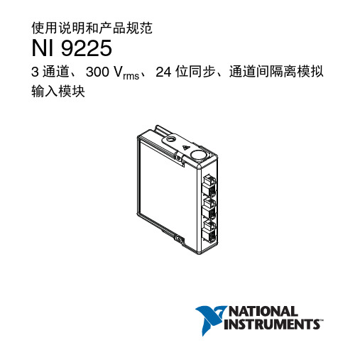
NI 9263使用说明和产品规范
使用说明和产品规范NI9225
AI0+ 0 AI0– 1 AI1+ 0 AI1– 1 AI2+ 0 AI2– 1
NI 9225 使用说明和产品规范 | © National Instruments | 7
NI 9225 可连接接地或浮接信号源。将信号源的正极连接至 AI+ 端子,信号源负极连接至 AI- 端子。 NI 9225 和信号源之 间为接地连接时,为保证 NI 9225 的正常运行,请确保 AI+ 和 AI- 之间的电压位于通道对地安全电压范围内。关于工作 电压和过压保护的详细信息见产品规范。
危险电压安全守则
模块连接危险电压时,请采取下列防范措施。危险电压是指 峰值电压高于 42.4 Vpk 的交流电压或高于 60 V 的直流电压。
注意 确保危险电压的连接由具有当地电气安全资质 的专业人士完成。
NI 9225 使用说明和产品规范 | © National Instruments | 3
注意 请勿将危险电压电路和人体可接触电路放置在 同一模块内。 注意 确保人体与设备及连至该模块的电路有效隔 离。 注意 模块端子接通危险电压 (>42.4 Vpk/60 VDC) 时,应确保人体与设备及连至该模块的电路有效隔 离。此时必须使用 NI 9971 连接器后壳套件,避免人 体与端子意外接触。 图 1 为 NI 9971 连接器后壳示意图。
注意 为满足海事应用中对射频辐射的要求,应使用 屏蔽式线缆并将系统置于金属外壳内。模块和控制器 的电源输入端必须安装抑制电磁干扰的磁箍。电源输 入线缆和模块输出线缆必须位于金属外壳上相对的两 侧。
6 | | NI 9225 使用说明和产品规范
连接 NI 9225
NI 9225 带有 3 个 2 端子可拆卸式螺栓端子连接器,可提供 3 个同步采样隔离模拟输入通道的连接。
NI USB-6216 USB多功能I O设备产品规范说明书
产品规范USB-6216隔离16 AI(16位、400 kS/s)、2 AO (250 kS/s)、最高32 DIO USB 多功能I/O设备这些产品规范适用于USB-6216 BNC、USB-6216 Mass终端和USB-6216弹簧端子。
定义担保产品规范给出了型号在规定操作条件下的性能,其中内容涵盖于型号质量担保中。
下列特性产品规范给出了型号在规定操作条件下使用的相关值,但其中内容未涵盖于型号质量担保中。
•常规产品规范给出了多数型号符合的性能。
•额定产品规范给出了基于设计、一致性测试或补充测试的属性。
除非另外声明,否则产品规范为常规产品规范。
条件除非另外声明,否则下列规范的适用温度均为25 °C。
模拟输入通道数8个差分或16个单端ADC分辨率16位DNL保证无丢失代码INL请参考AI绝对精度采样率单通道最大值400 kS/s多通道最大值(多路综合)400 kS/s最小值0 S/s定时分辨率50 ns定时精度采样率的50 ppm输入耦合DC输入范围±0.2 V、±1 V、±5 V、±10 V±10.4 V,AI GND模拟输入的最大工作电压(信号+共模)CMRR(DC至60 Hz)100 dB输入阻抗设备开启AI+对AI GND>10 GΩ,与100 pF电容并联AI-对AI GND>10 GΩ,与100 pF电容并联设备关闭AI+对AI GND1,200 ΩAI-对AI GND1,200 Ω输入偏置电流±100 pA串扰(100 kHz)相邻通道-75 dB非相邻通道-90 dB小信号带宽(-3 dB) 1.5 MHz输入FIFO容量4,095个采样扫描列表内存4,095项数据传输USB信号流、编程控制I/O 所有模拟输入和SENSE通道的过压保护设备开启±30 V,最多2个AI引脚设备关闭±20 V,最多2个AI引脚过压时的输入电流±20 mA/AI引脚,最大值多通道测量的稳定时间精度、全幅跳变、全量程跳变的±90 ppm (±6 LSB) 2.5 μs转换间隔跳变的±30 ppm (±2 LSB) 3.5 μs转换间隔跳变的±15 ppm (±1 LSB) 5.5 μs转换间隔2||USB-6216产品规范典型特性图图1. 稳定误差和不同源阻抗时间的关系时间 (µs)误差(跳变大小的p p m)图2. AI CMRR40608010012060100 1 k 10 k 100 k频率 (Hz)C M R R (d B )140AI 绝对精度(担保)注: 自设备外部校准起,表中给出精度的有效期为一年。
NI sbRIO-9627单板RIOOEM设备使用指南说明书
GETTING STARTED GUIDENI sbRIO-9627Single-Board RIO OEM DevicesThis document describes how to begin using the NI sbRIO-9627.Safety GuidelinesOperate the sbRIO-9627 only as described in the user documentation.Caution The sbRIO-9627 must be installed in a suitable enclosure prior to use.Caution NI makes no product safety, electromagnetic compatibility (EMC), or CEmarking compliance claims for the sbRIO-9627. The end-product supplier isresponsible for conformity to any and all compliance requirements.Caution Exercise caution when designing an enclosure for the sbRIO-9627.Auxiliary cooling may be necessary to keep the sbRIO-9627 within the specifiedoperating temperature range. Refer to the NI sbRIO-9627 Specifications on /manuals for more information about the maximum operating temperature rating. Forinformation and examples regarding factors that can affect thermal performance,visit /info and enter the Info Code sbriocooling.Caution Do not operate the sbRIO-9627 in a manner not specified in thisdocument. Product misuse can result in a hazard. You can compromise the safetyprotection built into the product if the product is damaged in any way. If the productis damaged, return it to NI for repair.Safety VoltagesConnect only voltages that are below these limits.V terminal to C terminal30 VDC maximum, Measurement Category I Measurement Category I is for measurements performed on circuits not directly connected to the electrical distribution system referred to as MAINS voltage. MAINS is a hazardous live electrical supply system that powers equipment. This category is for measurements of voltages from specially protected secondary circuits. Such voltage measurements include signal levels, special equipment, limited-energy parts of equipment, circuits powered by regulated low-voltage sources, and electronics.Caution Do not connect the sbRIO-9627 to signals or use for measurements withinMeasurement Categories II, III, or IV.Preparing the EnvironmentEnsure that the environment in which you are using the sbRIO-9627 meets the following specifications.-40 °C to 85 °CLocal ambient operating temperature neardevice (IEC 60068-2-1, IEC 60068-2-2)Maximum reported onboard sensor temperatureCPU/FPGA temperature98 °CPrimary System temperature85 °CSecondary System temperature85 °CNote Ensure that the local ambient, reported CPU/FPGA, and reported PrimarySystem temperatures do not exceed any of the maximum temperatures listed in thisdocument. For more information about how to access the onboard sensors, visit/info and enter the Info Code sbriosensors.Operating humidity (IEC 60068-2-78)10% RH to 90% RH, noncondensing Pollution Degree (IEC 60664)2Maximum altitude5,000 mIndoor use only.Note Refer to the device specifications on /manuals for completespecifications.2| | NI sbRIO-9627 Getting Started GuideUnpacking the KitCaution To prevent electrostatic discharge (ESD) from damaging the device,ground yourself using a grounding strap or by holding a grounded object, such asyour computer chassis.1.Touch the antistatic package to a metal part of the computer chassis.2.Remove the device from the package and inspect the device for loose components or anyother sign of damage.Caution Never touch the exposed pins of connectors.Note Do not install a device if it appears damaged in any way.3.Unpack any other items and documentation from the kit.Store the device in the antistatic package when the device is not in use.Verifying the Kit ContentsVerify that the following items are included in the sbRIO-9627 kit.NI sbRIO-9627 Getting Started Guide| © National Instruments| 31.sbRIO Device2.NI CompactRIO Device Drivers Media3.Getting Started Guide4.Power Supply5.10-pin IDC to 9-pin DSUB Cable6.50-pin IDC Ribbon Cable7.Power Cable Assembly8.Standoffs and Screws9.NI 9694 Digital I/O Breakout RMC BoardNote The provided power supply is only intended for the getting startedexperience. NI recommends the use of a power supply that meets the specifications listed in the NI sbRIO-9627 Specifications for system deployment.Installing Software on the Host ComputerBefore using the sbRIO-9627, you must install the following application software and device drivers on the host bVIEW 2015 or laterbVIEW Real-Time Module 2015 or laterbVIEW FPGA Module 2015 or later4.NI CompactRIO Device Drivers August 2015 or laterFor minimum software support information, visit /info and enter the Info Code softwareversion .Connecting the sbRIO-9627The sbRIO-9627 has the following components.4 | | NI sbRIO-9627 Getting Started Guide1.W3, RS-485 (COM3)2.W4, RS-232 (COM2)3.J6, SDHC4.J9, Power Connector5.Chassis Ground Bracket6.J10, USB Host Port7.W1, CAN (CAN0)8.J7, RJ-45 Ethernet Port 9.W2, RS-232 (COM1)10.Reset Switch 11.LEDs 12.J5, MIO13.Mounting Holes Connected to Chassis Ground 14.Ethernet RGMII T ransceiver 15.ULPI USB Transceiver 16.FPGA Processor 17.DDR Memory 18.NAND Flash 19.CPLD20.J1, RIO Mezzanine Card ConnectorConnecting the sbRIO-9627 to PowerThe NI sbRIO device requires a 9 VDC to 30 VDC external power supply. The NI sbRIO device filters and regulates the supplied power and provides power for RMCs.Note Refer to the Power Requirements section of the NI sbRIO-9627Specifications for the complete power requirement specifications.Note Refer to the Power Requirements section of the NI sbRIO-9627 User Manualfor formulas and examples for calculating power requirements for different configurations and application types.Note Refer to the Power Requirements section of the NI sbRIO-9627 User Manualfor proper wiring of the power cable assembly.Complete the following steps to connect a power supply to the device.Caution Do not mate or unmate the power supply connectors while power isapplied.1.Ensure that your power supply is powered off.2.Insert the power connector plug into the power connector receptacle of the NI sbRIO device until the connector latches into place.NI sbRIO-9627 Getting Started Guide | © National Instruments | 53.Turn on the power supply.Powering On the NI sbRIO DeviceThe NI sbRIO device runs a power-on self test (POST) when you apply power to the device. During the POST, the Power and Status LEDs turn on. When the Status LED turns off, the POST is complete. If the LEDs do not behave in this way when the system powers on, refer to the STATUS LED Indicators section.Connecting the sbRIO-9627 to the Host Computer Complete the following steps to connect the sbRIO-9627 to the host computer using the RJ-45 Ethernet port.1.Power on the host computer.2.Connect the sbRIO-9627 to the host computer using a standard Category 5 (CAT-5) orbetter shielded, twisted-pair Ethernet cable.Caution To prevent data loss and to maintain the integrity of your Ethernetinstallation, do not use a cable longer than 100 m.The first time you power up the device, it attempts to initiate a DHCP networkconnection. If the device is unable to initiate a DHCP connection, it connects to thenetwork with a link-local IP address with the form 169.254.x.x. After the device haspowered up, you must install software on the device and configure the network settings in MAX.Note Installing software may change the network behavior of the device. Forinformation about network behavior by installed software version, visit /info and enter the Info Code ipconfigcrio.Configuring the System in Measurement & Automation Explorer (MAX)Complete the following steps to find the system in MAX.unch MAX on the host computer.2.Expand Remote Systems in the configuration tree and locate your system.3.Tip MAX lists the system under the model number followed by the serialnumber, such as NI-sbRIO-9627-########.Complete the following steps to set a system password.Note The default username for the sbRIO-9627 is admin. There is no defaultpassword for the sbRIO-9627, so you must leave the password field blank whenlogging in until you set a system password.6| | NI sbRIO-9627 Getting Started Guide1.Right-click your system and select Web Configuration.The NI Web-Based Configuration and Monitoring utility opens in your default browser and is where you set the password. If you have not installed Microsoft Silverlight,NI Web-based Configuration & Monitoring prompts you to do so.2.Enter a unique name for your system in the Hostname field.3.Click the Security Configuration icon.4.Click Login.5.In the Login dialog box, enter the username admin and leave the password field blank.6.Click OK.7.Click Change Password.8.Enter and re-enter a new password.9.Click OK.10.Click Save.11.Click OK to confirm you are changing the password.Caution NI cannot recover lost system passwords. If you forget the password,you must contact NI and reformat the controller.Installing Software on the sbRIO-9627Complete the following steps to install software on the sbRIO-9627.1.In MAX, expand your system under Remote Systems.2.Right-click Software.3.Add/Remove Software to launch the LabVIEW Real-Time Software Wizard.Tip You must log in if you set a system password.4.5.Click Next.6.Select NI Scan Engine from the software add-ons.Select any additional software to install. If you plan on using the sbRIO-9627 with theNext.Tip You can use this wizard at anytime to install additional software.7.Next.8.9.Click Next to start the installation.10.Click Finish when the installation is complete.NI sbRIO-9627 Getting Started Guide| © National Instruments| 7T roubleshooting the sbRIO-9627The sbRIO-9627 is Not Communicating with the Network•Ensure that the Ethernet connections between the sbRIO-9627 and the host computer and the Ethernet connections between the host computer and the router are secure.•Ensure that you have the correct version of NI CompactRIO Device Drivers installed on the host computer. Visit /info and enter the Info Code softwareversion for theTip If you have recently upgraded LabVIEW, you must reinstall NICompactRIO Device Drivers.•e a standard Category 5 (CAT-5) or better shielded, twisted-pair Ethernet cable toconnect the sbRIO-9627 Ethernet port to a host computer. The sbRIO-9627 attempts to initiate a DHCP network connection at powerup.2.In MAX, expand your system under Remote Systems and select Troubleshoot RemoteSystem Discovery.System ResetThe following figure shows the reset behavior of the sbRIO-9627.Figure 3. Reset Button BehaviorPress and hold8| | NI sbRIO-9627 Getting Started GuideSTA TUS LED IndicatorsThe following table lists the STATUS LED indicators.NI sbRIO-9627 Getting Started Guide| © National Instruments| 9Where to Go NextWorldwide Support and ServicesThe National Instruments website is your complete resource for technical support. At / support, you have access to everything from troubleshooting and application development self-help resources to email and phone assistance from NI Application Engineers.Visit /services for NI Factory Installation Services, repairs, extended warranty, and other services.Visit /register to register your National Instruments product. Product registration facilitates technical support and ensures that you receive important information updates from NI.National Instruments corporate headquarters is located at 11500 North Mopac Expressway, Austin, Texas, 78759-3504. National Instruments also has offices located around the world. For telephone support in the United States, create your service request at /support or 10| | NI sbRIO-9627 Getting Started Guidedial 1 866 ASK MYNI (275 6964). For telephone support outside the United States, visit the Worldwide Offices section of /niglobal to access the branch office websites, which provide up-to-date contact information, support phone numbers, email addresses, and current events.NI sbRIO-9627 Getting Started Guide| © National Instruments| 11Refer to the NI Trademarks and Logo Guidelines at /trademarks for information on National Instruments trademarks. Other product and company names mentioned herein are trademarks or trade names of their respective companies. For patents covering National Instruments products/technology, refer to the appropriate location: Help»Patents in your software, the patents.txt file on your media, or the National Instruments Patent Notice at /patents. Y ou can find information about end-user license agreements (EULAs) and third-party legal notices in the readme file for your NI product. Refer to the ExportCompliance Information at /legal/export-compliance for the National Instruments global trade compliance policy and how to obtain relevant HTS codes, ECCNs, and other import/export data. NI MAKES NO EXPRESS OR IMPLIED WARRANTIES AS TO THE ACCURACY OF THE INFORMATION CONT AINED HEREIN AND SHALL NOT BE LIABLE FOR ANY ERRORS. U.S. Government Customers: The data contained in this manual was developed at private expense and is subject to the applicable limited rights and restricted data rights as set forth in FAR 52.227-14, DFAR 252.227-7014, and DFAR 252.227-7015.© 2014—2015 National Instruments. All rights reserved.376415A-01Aug15。
NI sbRIO-9637单板RIO OEM设备开始使用指南说明书
GETTING STARTED GUIDENI sbRIO-9637Single-Board RIO OEM DevicesThis document describes how to begin using the NI sbRIO-9637.Safety GuidelinesOperate the sbRIO-9637 only as described in the user documentation.Caution The sbRIO-9637 must be installed in a suitable enclosure prior to use.Caution NI makes no product safety, electromagnetic compatibility (EMC), or CEmarking compliance claims for the sbRIO-9637. The end-product supplier isresponsible for conformity to any and all compliance requirements.Caution Exercise caution when designing an enclosure for the sbRIO-9637.Auxiliary cooling may be necessary to keep the sbRIO-9637 within the specifiedoperating temperature range. Refer to the NI sbRIO-9637 Specifications on /manuals for more information about the maximum operating temperature rating. Forinformation and examples regarding factors that can affect thermal performance,visit /info and enter the Info Code sbriocooling.Caution Do not operate the sbRIO-9637 in a manner not specified in thisdocument. Product misuse can result in a hazard. You can compromise the safetyprotection built into the product if the product is damaged in any way. If the productis damaged, return it to NI for repair.Safety VoltagesConnect only voltages that are below these limits.V terminal to C terminal30 VDC maximum, Measurement Category I Measurement Category I is for measurements performed on circuits not directly connected to the electrical distribution system referred to as MAINS voltage. MAINS is a hazardous live electrical supply system that powers equipment. This category is for measurements of voltages from specially protected secondary circuits. Such voltage measurements include signal levels, special equipment, limited-energy parts of equipment, circuits powered by regulated low-voltage sources, and electronics.Caution Do not connect the sbRIO-9637 to signals or use for measurements withinMeasurement Categories II, III, or IV.Preparing the EnvironmentEnsure that the environment in which you are using the sbRIO-9637 meets the following specifications.-40 °C to 85 °CLocal ambient operating temperature neardevice (IEC 60068-2-1, IEC 60068-2-2)Maximum reported onboard sensor temperatureCPU/FPGA temperature98 °CPrimary System temperature85 °CSecondary System temperature85 °CNote Ensure that the local ambient, reported CPU/FPGA, and reported PrimarySystem temperatures do not exceed any of the maximum temperatures listed in thisdocument. For more information about how to access the onboard sensors, visit/info and enter the Info Code sbriosensors.Operating humidity (IEC 60068-2-78)10% RH to 90% RH, noncondensing Pollution Degree (IEC 60664)2Maximum altitude5,000 mIndoor use only.Note Refer to the device specifications on /manuals for completespecifications.2| | NI sbRIO-9637 Getting Started GuideUnpacking the KitCaution To prevent electrostatic discharge (ESD) from damaging the device,ground yourself using a grounding strap or by holding a grounded object, such as your computer chassis.1.Touch the antistatic package to a metal part of the computer chassis.2.Remove the device from the package and inspect the device for loose components or anyother sign of damage.CautionNever touch the exposed pins of connectors.Note Do not install a device if it appears damaged in any way.3.Unpack any other items and documentation from the kit.Store the device in the antistatic package when the device is not in use.Verifying the Kit ContentsVerify that the following items are included in the sbRIO-9637 kit.Figure 1.sbRIO-9637 Kit Contents1.sbRIO Device2.NI CompactRIO Device Drivers Media3.Getting Started Guide4.Power Supply5.10-pin IDC to 9-pin DSUB Cable6.50-pin IDC Ribbon Cable7.Power Cable Assembly8.Standoffs and ScrewsNote The provided power supply is only intended for the getting startedexperience. NI recommends the use of a power supply that meets the specifications listed in the NI sbRIO-9637 Specifications for system deployment.NI sbRIO-9637 Getting Started Guide | © National Instruments | 3Installing Software on the Host ComputerBefore using the sbRIO-9637, you must install the following application software and device drivers on the host computer.bVIEW 2015 or laterbVIEW Real-Time Module 2015 or laterbVIEW FPGA Module 2015 or later4.NI CompactRIO Device Drivers August 2015 or laterFor minimum software support information, visit /info and enter the Info Code softwareversion.Connecting the sbRIO-9637The sbRIO-9637 has the following components.Figure 2. sbRIO-9637 Components1.W3, RS-485 (COM3)2.W4, RS-232 (COM2)3.J6, SDHC4.J9, Power Connector5.Chassis Ground Bracket6.J10, USB Host Port7.W1, CAN (CAN0)8.J7, RJ-45 Ethernet Port9.W2, RS-232 (COM1)10.Reset Switch 11.LEDs12.J4, DIO13.J5, MIO14.Mounting Holes Connected to Chassis Ground15.Ethernet RGMII Transceiver16.ULPI USB T ransceiver17.FPGA Processor18.DDR Memory19.NAND Flash20.CPLD4| | NI sbRIO-9637 Getting Started GuideConnecting the sbRIO-9637 to PowerThe NI sbRIO device requires a 9 VDC to 30 VDC external power supply. The NI sbRIO device filters and regulates the supplied power and provides power for RMCs.Note Refer to the Power Requirements section of the NI sbRIO-9637Specifications for the complete power requirement specifications.Note Refer to the Power Requirements section of the NI sbRIO-9637 User Manualfor formulas and examples for calculating power requirements for differentconfigurations and application types.Note Refer to the Power Requirements section of the NI sbRIO-9637 User Manualfor proper wiring of the power cable assembly.Complete the following steps to connect a power supply to the device.Caution Do not mate or unmate the power supply connectors while power isapplied.1.Ensure that your power supply is powered off.2.Insert the power connector plug into the power connector receptacle of the NI sbRIOdevice until the connector latches into place.3.Turn on the power supply.Powering On the NI sbRIO DeviceThe NI sbRIO device runs a power-on self test (POST) when you apply power to the device. During the POST, the Power and Status LEDs turn on. When the Status LED turns off, the POST is complete. If the LEDs do not behave in this way when the system powers on, refer to the STATUS LED Indicators section.Connecting the sbRIO-9637 to the Host Computer Complete the following steps to connect the sbRIO-9637 to the host computer using the RJ-45 Ethernet port.1.Power on the host computer.2.Connect the sbRIO-9637 to the host computer using a standard Category 5 (CAT-5) orbetter shielded, twisted-pair Ethernet cable.Caution To prevent data loss and to maintain the integrity of your Ethernetinstallation, do not use a cable longer than 100 m.The first time you power up the device, it attempts to initiate a DHCP networkconnection. If the device is unable to initiate a DHCP connection, it connects to thenetwork with a link-local IP address with the form 169.254.x.x. After the device hasNI sbRIO-9637 Getting Started Guide| © National Instruments| 5powered up, you must install software on the device and configure the network settings in MAX.Note Installing software may change the network behavior of the device. Forinformation about network behavior by installed software version, visit /info and enter the Info Code ipconfigcrio.Configuring the System in Measurement & Automation Explorer (MAX)Complete the following steps to find the system in MAX.unch MAX on the host computer.2.Expand Remote Systems in the configuration tree and locate your system.3.Tip MAX lists the system under the model number followed by the serialnumber, such as NI-sbRIO-9637-########.Complete the following steps to set a system password.Note The default username for the sbRIO-9637 is admin. There is no defaultpassword for the sbRIO-9637, so you must leave the password field blank whenlogging in until you set a system password.1.Right-click your system and select Web Configuration.The NI Web-Based Configuration and Monitoring utility opens in your default browser and is where you set the password. If you have not installed Microsoft Silverlight,NI Web-based Configuration & Monitoring prompts you to do so.2.Enter a unique name for your system in the Hostname field.3.Click the Security Configuration icon.4.Click Login.5.In the Login dialog box, enter the username admin and leave the password field blank.6.Click OK.7.Click Change Password.8.Enter and re-enter a new password.9.Click OK.10.Click Save.11.Click OK to confirm you are changing the password.Caution NI cannot recover lost system passwords. If you forget the password,you must contact NI and reformat the controller.6| | NI sbRIO-9637 Getting Started GuideInstalling Software on the sbRIO-9637Complete the following steps to install software on the sbRIO-9637.1.In MAX, expand your system under Remote Systems.2.Right-click Software.3.Add/Remove Software to launch the LabVIEW Real-Time Software Wizard.Tip You must log in if you set a system password.4.5.Click Next.6.Select NI Scan Engine from the software add-ons.Select any additional software to install. If you plan on using the sbRIO-9637 with theNext.Tip You can use this wizard at anytime to install additional software.7.Next.8.9.Click Next to start the installation.10.Click Finish when the installation is complete.Troubleshooting the sbRIO-9637The sbRIO-9637 is Not Communicating with the Network•Ensure that the Ethernet connections between the sbRIO-9637 and the host computer and the Ethernet connections between the host computer and the router are secure.•Ensure that you have the correct version of NI CompactRIO Device Drivers installed on the host computer. Visit /info and enter the Info Code softwareversion for theTip If you have recently upgraded LabVIEW, you must reinstall NICompactRIO Device Drivers.•e a standard Category 5 (CAT-5) or better shielded, twisted-pair Ethernet cable toconnect the sbRIO-9637 Ethernet port to a host computer. The sbRIO-9637 attempts to initiate a DHCP network connection at powerup.NI sbRIO-9637 Getting Started Guide| © National Instruments| 72.In MAX, expand your system under Remote Systems and select Troubleshoot RemoteSystem Discovery.System ResetThe following figure shows the reset behavior of the sbRIO-9637.Figure 3. Reset Button BehaviorPress and holdPress and holdRESET button for ≥ 5 sSTA TUS LED IndicatorsThe following table lists the STATUS LED indicators.8| | NI sbRIO-9637 Getting Started GuideTable 1. ST ATUS LED IndicatorsNI sbRIO-9637 Getting Started Guide| © National Instruments| 9Where to Go NextWorldwide Support and ServicesThe National Instruments website is your complete resource for technical support. At / support, you have access to everything from troubleshooting and application development self-help resources to email and phone assistance from NI Application Engineers.Visit /services for NI Factory Installation Services, repairs, extended warranty, and other services.Visit /register to register your National Instruments product. Product registration facilitates technical support and ensures that you receive important information updates from NI.National Instruments corporate headquarters is located at 11500 North Mopac Expressway, Austin, Texas, 78759-3504. National Instruments also has offices located around the world. For telephone support in the United States, create your service request at /support or 10| | NI sbRIO-9637 Getting Started Guidedial 1 866 ASK MYNI (275 6964). For telephone support outside the United States, visit the Worldwide Offices section of /niglobal to access the branch office websites, which provide up-to-date contact information, support phone numbers, email addresses, and current events.NI sbRIO-9637 Getting Started Guide| © National Instruments| 11Refer to the NI Trademarks and Logo Guidelines at /trademarks for information on National Instruments trademarks. Other product and company names mentioned herein are trademarks or trade names of their respective companies. For patents covering National Instruments products/technology, refer to the appropriate location: Help»Patents in your software, the patents.txt file on your media, or the National Instruments Patent Notice at /patents. Y ou can find information about end-user license agreements (EULAs) and third-party legal notices in the readme file for your NI product. Refer to the ExportCompliance Information at /legal/export-compliance for the National Instruments global trade compliance policy and how to obtain relevant HTS codes, ECCNs, and other import/export data. NI MAKES NO EXPRESS OR IMPLIED WARRANTIES AS TO THE ACCURACY OF THE INFORMATION CONT AINED HEREIN AND SHALL NOT BE LIABLE FOR ANY ERRORS. U.S. Government Customers: The data contained in this manual was developed at private expense and is subject to the applicable limited rights and restricted data rights as set forth in FAR 52.227-14, DFAR 252.227-7014, and DFAR 252.227-7015.© 2014—2015 National Instruments. All rights reserved.376416A-01Aug15。
NI9222-9223使用说明和产品规范
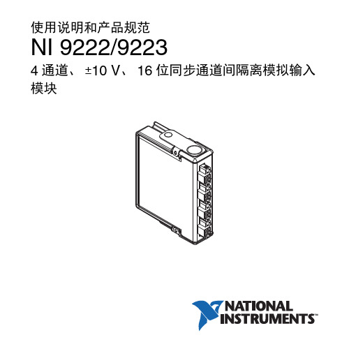
NI 9222/9223 使用说明和产品规范 | © National Instruments | 3
注意 电源未断开或处于非安全环境时,请勿卸除模 块。
注意 替换组件可能影响模块在环境等级为 Class I, Division 2 时的适用性。
1 MS/s
1 MS/s
350 kS/s
* FPGA 用户控制 I/O 采样允许以底层访问权限进行采样和传 输,并提供较高的采样率。关于 NI 9222/9223 的 FPGA 用户控 制 I/O 采样的详细信息,请访问 /info,输入信息代码 samplerate 查询。
16 | | NI 9222/9223 使用说明和产品规范
注意 必须确保瞬时干扰不超过额定电压的 140%。
4 | | NI 9222/9223 使用说明和产品规范
注意 系统应安装在 ATEX 认证的外壳中,外壳最小 防护等级不低于 IP54 (IEC/EN 60529),且环境的污染 等级小于等于 2。
注意 外壳必须带有仅能通过工具开启的挡板或壳 盖。
最小值 *
测量电压, AI+ - AI常规值
最大值
±10.5 V
±10.6 V
±10.7 V
* 最小测量电压范围指 NI 9222/9223 可精确测量的最大电压。
过压保护......................................................±30 V
1 关于安全操作电压的详细信息,见安全守则。
注意 对于 Division 2 和 Zone 2 环境中的应用,应将 系统安装在防护等级不低于 IP 54 (IEC 60529 和 EN 60529)的外壳内。 危险环境下的特殊要求 (欧洲) 设备在 DEMKO 认证 No. 07 ATEX 0626664X 中的评定等级 为 Ex nA IIC T4 。每个模块均标有 II 3G 并适用于危险环 境 Zone 2,环境温度为 -40 °C ≤ Ta ≤ 70 °C。如在 Gas Group IIC 危险环境中使用 NI 9222/9223, NI 机箱的防护等级必须 为 Ex nC IIC T4、 EEx nC IIC T4、 Ex nA IIC T4 或 Ex nL IIC T4 之一。
第3部分:综合布线用连接硬件技术要求(YD.T 926.3)

中华人民共和国通信行业标准大楼通信综合布线系统第3部分:综合布线用连接硬件技术要求YD/T 926.3—2001 neq ISO/IEC 11801:1999 代替YD/T926.3—19981 范围本部分规定了综合布线用连接硬件的主要机械物理性能、电气特性、可靠性要求、试验方法、检验规则及安装要求等。
本部分规定的连接硬件包括连接器(包括插头、插座)及其组件和接插软线。
本部分适用于综合布线用连接硬件的设计、生产与选用。
本部分不包括某些应用系统对连接硬件的特殊要求。
本部分不包括有源或无源电子线路的中间适配器或其它器件(如:变量器、匹配电阻、滤波器和保护器件等)的技术要求。
本标准中各类对称电缆布线用连接硬件的最高传输频率分别为:3类 16 MH Z4类20 MH Z5类100 MH Z5e类100 MH Z,们允许支持双工的应用2 引用标准下列标准所包含的条文,通过在本标准中引用而构成为本标准的条文。
本标准出版时,所示版本均为有效。
所有标准都会被修订,使用本标准的各方应探讨使用下列标准最新版本的可能性。
GB/T242l-1999 电工电子产品环境试验第1部分:总则GB/T 2423.2-1989 电工电子产品基本环境试验规程试验B:高温试验方法GB/T 2423.10-1995 电工电子产品环境试验第2部分:试验方法试验Fc和导则:振动(正弦) GB/T 2423.34-1986 电工电子产品基本环境试验规程试验Z/AD:温度/湿度组合循环试验方法GB/T 2423.5l-2000 电工电子产品环境试验第2部分:试验方法试验Ke:流动混合气体腐蚀试验GB/T 2424.11-1982 电工电子产品基本环境试验规程接触件和连接件的二氧化硫试验导则GB/T 2424.12-1982 电工电子产品基本环境试验规程接触件和连接件的硫化氢试验导则GB/T 2951.4-1994 电线电缆机械性能试验方法外径测量GB/T 4909.2-1985 裸电线试验方法尺寸测量GB/T 5095-1985 电子设备用机电元件基本试验规程与测量方法GB/T 5169.7-1985 电工电子产品着火危险试验本生灯型火焰试验方法GB/T 11327.1-1:1999 聚氯乙烯绝缘聚氯乙烯护套低频电线电缆第1部分:通用试验测量方法GB/T 12507.1-2000 光纤光缆连接器第1部分:总规范GB/T 15629.5-1996 信息技术局域网和城域网第5部分:令牌环访问方法和物理层规范GB/T 15972.2-1998 光纤总规范第2部分:尺寸参数试验方法GB/T 17737.1-2000 射频电缆第1部分:总规范——总则、定义。
NI 9263说明书

OPERATING INSTRUCTIONS AND SPECIFICATIONS NI 92634-Channel, ±10 V, 16-Bit Analog Voltage Output ModuleNI 9263 Operating Instructions and Specifications This doc u ment describes how to u se the National Instr u ments 9263 and incl u des specifications and terminal assignments for the NI 9263. Visit /info and enter rd s oftwarever s ion to determine which software yo u need for the mod u les yo u are u sing. For information abo u t installing, config u ring, and programming the system, refer to the system doc u mentation. Visit /info and enter c s erie s doc for information abo u t C Series doc u mentation.NoteThe safety g u idelines and specifications in thisdoc u ment are specific to the NI 9263. The othercomponents in the system might not meet the same safety ratings and specifications. Refer to the doc u mentation for each component in the system to determine the safety ratings and specifications for the entire system. Visit /info and enter c s erie s doc for information abo u t C Series doc u mentation.Safety GuidelinesOperate the NI 9263 only as described in these operating instr u ctions.Hot SurfaceThis icon denotes that the component may behot. To u ching this component may res u lt in bodily inj ury.© National Instruments Corp.3NI 9263 Operating Instructions and Specifications Safety Guidelines for Hazardous VoltagesIf hazardo u s voltages are connected to the mod u le, take the following preca u tions. A hazardo u s voltage is a voltage greater than 42.4 V pk or 60 VDC to earth gro u nd.Caution Ens u re that hazardo u s voltage wiring isperformed only by q u alified personnel adhering to local electrical standards.CautionDo not mix hazardo u s voltage circ u its andh u man-accessible circ u its on the same mod u le.Caution Make s u re that devices and circ u its connected to the mod u le are properly ins u lated from h u man contact.CautionWhen mod u le terminals are hazardo u s voltageLIVE (>42.4 V pk /60 VDC), yo u m u st ens u re that devices and circ u its connected to the mod u le are properlyins u lated from h u man contact. Yo u m u st u se the NI 9932 connector backshell kit to ens u re that the terminals are notaccessible.NI 9263 Operating Instructions and Specifications Fig u re 1 shows the NI 9932 connector backshell.Figure 1. NI 9932 Connector BackshellSafety Guidelines for Hazardous LocationsThe NI 9263 is s u itable for u se in Class I, Division 2, Gro u ps A, B, C, D, T4 hazardo u s locations; Class I, Zone 2, AEx nA IIC T4, and Ex nA IIC T4 hazardo u s locations; and nonhazardo u s locations only. Follow these g u idelines if yo u are installing the NI 9263 in a potentially explosive environment. Not following these g u idelines may res u lt in serio u s inj ury or death.© National Instruments Corp.5NI 9263 Operating Instructions and Specifications Caution Do not disconnect I/O-side wires or connectors u nless power has been switched off or the area is known to be nonhazardo u s.Caution Do not remove mod u les u nless power has been switched off or the area is known to be nonhazardo u s.Caution S u bstit u tion of components may impairs u itability for Class I, Division 2.CautionFor Zone 2 applications, install the systemin an enclos u re rated to at least IP 54 as defined byIEC 60529 and EN 60529.Special Conditions for Hazardous Locations Use in Europe This eq u ipment has been eval u ated as Ex nA IIC T4 eq u ipment u07ATEX 0626664X. Each mod u le u itable for u se in Zone 2 hazardo u s u res of –40°C ≤Ta ≤70°C. If yo u are u sing the NI 9263 in Gas Gro u p IIC hazardo u s locations, yo u m u st u se the device in an NI chassis that has been eval u ated as Ex nC IIC T4, EEx nC IIC T4, Ex nA IIC T4, or Ex nL IIC T4 eq u ipment.NI 9263 Operating Instructions and Specifications Special Conditions for Marine ApplicationsSome mod u les are Lloyd’s Register (LR) Type Approved for marine applications. To verify Lloyd’s Register certification, visit /certification and search for the LR certificate, or look for the Lloyd’s Register mark on the mod u le.Caution To meet radio freq u ency emission req u irements for marine applications, u se shielded cables and install the system in a metal enclos u re. S u ppression ferrites m u st be installed on power s u pply inp u ts near power entries to mod u les and controllers. Power s u pply and mod u le cables m u st be separated on opposite sides of the enclos u re and m u st enter and exit thro u gh opposingenclos ure walls.Connecting the NI 9263The NI 9263 has a 10-terminal, detachable screw-terminal connector that provides connections for 4 analog o u tp u t channels.Figure 2. NI 9263 Terminal Assignments© National Instruments Corp.7NI 9263 Operating Instructions and SpecificationsNI 9263 Operating Instructions and Specifications Each channel of the NI 9263 has an AO terminal and a common terminal, COM, and there is an additional COM terminal at the bottom of the connector. All of the COM terminals are internally connected to the isolated gro u nd reference of the mod u le. Yo u can connect a load to each channel of the NI 9263. Connect the positive lead of the load to the AO terminal, and the gro u nd of the load to the corresponding COM terminal. Refer to Fig u re 3 for an ill u stration of connecting a load to the NI 9263.Figure 3. Connecting a Load to the NI 9263Note Yo u m u st u se 2-wire ferr u les to create a sec u re connection when connecting more than one wire to a single terminal on the NI 9263.Each channel has a digital-to-analog converter (DAC) thatprod u ces a voltage signal. Each channel also has overvoltage and short-circ u it protection. Refer to the Specifications section for more information abo u t the overvoltage and short-circ u it protection. Refer to Fig u re4 for an ill u stration of the o u tp u tcirc u itry for one channel of the NI 9263.Figure 4. Output Circuitry for One Channel of the NI 9263 When the mod u le powers on, the channels o u tp u t the start u p voltage. Refer to the Specifications section for more information abo u t start u p voltage. Refer to the software help for information © National Instruments Corp.9NI 9263 Operating Instructions and SpecificationsNI 9263 Operating Instructions and Specifications abo u t config u ring start u p o u tp u t states in software. Visit /info and enter c s erie s doc for information abo u t C Series doc u mentation.Wiring for High-Vibration ApplicationsIf an application is s u bject to high vibration, National Instr u ments recommends that yo u either u se ferr u les to terminate wires to the detachable screw-terminal connector or u se the NI 9932 backshell kit to protect the connections. Refer to Fig u re 5 for an ill u stration of u sing ferr u les. Refer to Fig u re 1 for an ill u stration of the NI 9932 connector backshell.Figure 5.10-Terminal Detachable Screw-Terminal Connector with FerruleSleep ModeThis mod u le s u pports a low-power sleep mode. S u pport for sleep mode at the system level depends on the chassis that the mod u le is pl u gged into. Refer to the chassis man u al for information abo u t s u pport for sleep mode. If the chassis s u pports sleep mode, refer to the software help for information abo u t enabling sleep mode. Visit /info and enter c s erie s doc for information abo u tC Series doc u mentation.Typically, when a system is in sleep mode, yo u cannotcomm u nicate with the mod u les. In sleep mode, the systemcons u mes minimal power and may dissipate less heat than it does in normal mode. Refer to the Specifications section for more information abo u t power cons u mption and thermal dissipation.SpecificationsThe following specifications are typical for the range –40 to 70 °C u nless otherwise noted. All voltages are relative to COM u nless otherwise noted.Output CharacteristicsN u mber of channels..........................4 analog o u tp u t channels DAC resol u tion.................................16 bitsType of DAC.....................................StringPower-on o u tp u t state.......................Channels offStart u p voltage..................................0 V1Power-down voltage.........................0 V21 When the mod u le powers on, a glitch occ u rs for 20μs peaking at –1.5V.2 The power-down voltage peaks at 1.8V before exponentially discharging to 0V in 100μs. Yo u can add a 10kΩ load to red u ce the peak voltage.O u tp u t voltage rangeNominal......................................±10VMinim u m....................................±10.4VTypical........................................±10.7VMaxim u m...................................±11VC u rrent drive.....................................±1mA per channel max O u tp u t impedance.............................2ΩAcc u racyMeasurement ConditionsPercent ofReading(Gain Error)Percent ofRange*(Offset Error)Calibrated, max(–40 to 70°C)0.35%0.75% Calibrated, typ (25°C, ±5°C)0.03%0.1% Uncalibrated, max(–40 to 70°C) 2.2% 1.7% Uncalibrated, typ (25°C, ±5°C)0.3%0.25% * Range eq u als ±10.7 VStabilityGain drift....................................14ppm/°COffset drift..................................110μV/°CProtectionOvervoltage................................±30VShort-circ u it................................IndefinitelyUpdate timeNoiseUpdating at 100kS/s..................600 μV rmsNot u pdating...............................260 μV rms Number ofChannelsUpdate Time for NI cRIO-9151 R Series Expansion Chassis Update Time for All Other Chassis 13.5μs min 3μs min 26.5μs min 5μs min 39μs min 7.5μs min 412μs min 9.5μs minSlew rate...........................................4V/μs Crosstalk...........................................76dBSettling time (100 pF load, to 1 LSB)F u ll-scale step.............................20μs1V step.......................................13μs0.1V step....................................10μsCapacitive drive................................1,500 pF min Monotonicity.....................................16 bits DNL..................................................±1LSB maxINL (endpoint)..................................±12LSB max MTBF...............................................1,732,619 ho u rs at 25 °C;Bellcore Iss u e 2, Method 1,Case 3, Limited Part StressMethodNote Contact NI for Bellcore MTBF specificationsat other temperat u res or for MIL-HDBK-217Fspecifications.Power RequirementsPower cons u mption from chassisActive mode (at –40 °C).............500mW maxSleep mode.................................25μW maxThermal dissipation (at 70 °C)Active mode...............................750mW maxSleep mode.................................25μW maxPhysical CharacteristicsIf yo u need to clean the mod u le, wipe it with a dry towel.Note For two-dimensional drawings andthree-dimensional models of the C Series mod u le andconnectors, visit /dimen s ion s and search bymod u le n u mber.Screw-terminal wiring......................12 to 24 AWG coppercond u ctor wire with 10 mm(0.39 in.) of ins u lationstripped from the endTorq u e for screw terminals...............0.5 to 0.6 N · m(4.4to5.3lb· in.)Ferr u les.............................................0.25 mm2 to 2.5 mm2 Weight...............................................150g (5.3 oz)SafetyIsolation VoltagesConnect only voltages that are within the following limits. Channel-to-channel...........................NoneChannel-to-earth gro u ndContin u o u s.................................250V rms,Meas u rement Category II Withstand....................................2,300V rms, verified by a 5 sdielectric withstand test Division 2 and Zone 2 hazardo u s locations applications (Channel-to-earth gro u nd)................60 VDC,Meas u rement Category I Meas u rement Category I is for meas u rements performed oncirc u its not directly connected to the electrical distrib u tion system referred to as MAINS voltage. MAINS is a hazardo u s live electrical s u pply system that powers eq u ipment. This category is for meas u rements of voltages from specially protected secondarycirc u its. S u ch voltage meas u rements incl u de signal levels, special eq u ipment, limited-energy parts of eq u ipment, circ u its powered by reg u lated low-voltage so u rces, and electronics.Caution Do not connect to signals or u se formeas u rements within Meas u rement Categories II,III, or IV.Meas u rement Category II is for meas u rements performed on circ u its directly connected to the electrical distrib u tion system. This category refers to local-level electrical distrib u tion, s u ch as that provided by a standard wall o u tlet, for example, 115 V for U.S. or 230 V for E u rope.Caution Do not connect to signals or u se formeas u rements within Meas u rement Categories III or IV.Hazardous LocationsU.S. (UL)..........................................Class I, Division 2,Gro u ps A, B, C, D, T4;Class I, Zone 2,AEx nA IIC T4Canada (C-UL).................................Class I, Division 2,Gro u ps A, B, C, D, T4;Class I, Zone 2,Ex nA IIC T4E u rope (DEMKO).............................Ex nA IIC T4Safety StandardsThis prod u ct meets the req u irements of the following standards of safety for electrical eq u ipment for meas u rement, control, and laboratory u se:•IEC 61010-1, EN 61010-1•UL 61010-1, CSA 61010-1Note For UL and other safety certifications, refer to theprod u ct label or the Online Product Certification section.Electromagnetic CompatibilityThis prod u ct meets the req u irements of the following EMC standards for electrical eq u ipment for meas u rement, control, and laboratory u se:•EN 61326 (IEC 61326): Class A emissions; Ind u strial imm u nity•EN 55011 (CISPR 11): Gro u p 1, Class A emissions•AS/NZS CISPR 11: Gro u p 1, Class A emissions•FCC 47 CFR Part 15B: Class A emissions•ICES-001: Class A emissionsNote For the standards applied to assess the EMC of thisprod u ct, refer to the Online Product Certification section.Note For EMC compliance, operate this device withshielded cables.CE ComplianceThis prod u ct meets the essential req u irements of applicableE u ropean Directives as follows:•2006/95/EC; Low-V oltage Directive (safety)•2004/108/EC; Electromagnetic Compatibility Directive (EMC)Online Product CertificationRefer to the prod u ct Declaration of Conformity (DoC) for additional reg u latory compliance information. To obtainprod u ct certifications and the DoC for this prod u ct, visit / certification, search by mod u le n u mber or prod u ct line, and click the appropriate link in the Certification col u mn.Shock and VibrationTo meet these specifications, yo u m u st panel mo u nt the system and either affix ferr u les to the ends of the terminal wires or u se the NI9932 backshell kit to protect the connections.Operating vibrationRandom (IEC 60068-2-64).........5 g rms, 10 to 500 HzSin u soidal (IEC 60068-2-6).......5 g, 10 to 500 Hz© National Instruments Corp.21NI 9263 Operating Instructions and SpecificationsOperating shock(IEC 60068-2-27)..............................30 g, 11 ms half sine,50 g, 3 ms half sine,18 shocks at 6 orientations EnvironmentalNational Instr u ments C Series mod u les are intended for indoor u se only b u t may be u sed o u tdoors if installed in a s u itable enclos u re. Refer to the man u al for the chassis yo u are u sing for more information abo u t meeting these specifications.Operating temperat u re(IEC 60068-2-1, IEC 60068-2-2).....–40 to 70 °CStorage temperat u re(IEC 60068-2-1, IEC 60068-2-2).....–40 to 85 °CIngress protection..............................IP 40Operating h u midity(IEC 60068-2-56)..............................10 to 90% RH,noncondensingStorage h u midity(IEC 60068-2-56)..............................5 to 95% RH,noncondensingNI 9263 Operating Instructions and Maxim u m altit u de.............................2,000 mPoll u tion Degree (2)Environmental ManagementNational Instr u ments is committed to designing and man u fact u ring prod u cts in an environmentally responsible manner. NI recognizes that eliminating certain hazardo u s s u bstances from o u r prod u cts is beneficial to the environment and to NI c u stomers.For additional environmental information, refer to the NI and the Environment Web page at /environment. This page contains the environmental reg u lations and directives with which NI complies, as well as other environmental information notincl u ded in this doc u ment.Waste Electrical and Electronic Equipment (WEEE)EU Customers At the end of the life cycle, all prod u ctsmust be sent to a WEEE recycling center. For moreinformation abo u t WEEE recycling centers and NationalInstr u ments WEEE initiatives, visit /environment/weee.© National Instruments Corp.23NI 9263 Operating Instructions and SpecificationsNI 9263 Operating Instructions and Specifications CalibrationYo u can obtain the calibration certificate and information abo u t calibration services for the NI 9263 at /calibration .Calibration interval...........................1 year ⬉ ѻ ∵ ㅵ⧚ ⊩˄Ё RoHS ˅Ё National Instruments ヺ Ё ⬉ѻ Ё䰤 Փ⫼ ѯ ⠽䋼 Ҹ (RoHS)DŽ ѢNational Instruments Ё RoHS 㾘 ˈ䇋ⱏ/environmen t /rohs_china DŽ(For information about China RoHS compliance, go to /environmen t /rohs_china .)Where to Go for SupportThe National Instr u ments Web site is yo u r complete reso u rce for technical s u pport. At /s upport yo u have access to everything from tro u bleshooting and application development self-help reso u rces to email and phone assistance fromNI Application Engineers.National Instr u ments corporate headq u arters is located at 11500North Mopac Expressway, A u stin, Texas, 78759-3504. National Instr u ments also has offices located aro u nd the world to help address yo u r s u pport needs. For telephone s u pport in the United States, create yo u r service req u est at /s upport and follow the calling instr u ctions or dial 5127958248. For telephone s u pport o u tside the United States, contact yo u r local branch office:A u stralia1800300800, A u stria43662457990-0,Belgi u m32(0)27570020, Brazil551132623599,Canada8004333488, China862150509800,Czech Rep u blic420224235774, Denmark4545762600, Finland358(0)972572511, France0157662424, Germany49897413130, India918041190000,Israel97236393737, Italy390241309277, Japan0120-527196, © National Instruments Corp.25NI 9263 Operating Instructions and SpecificationsKorea820234513400, Lebanon961(0)1332828,Malaysia1800887710, Mexico018000100793, Netherlands31(0)348433466, New Zealand0800553322, Norway47(0)66907660, Poland48223289010,Port u gal351210311210, R u ssia74957836851,Singapore180********, Slovenia38634254200,So u th Africa270118058197, Spain34916400085, Sweden46(0)858789500, Switzerland41562005151, Taiwan8860223772222, Thailand6622786777,T u rkey902122793031, United Kingdom44(0)1635523545NI 9263 Operating Instructions and National Instruments, NI, , and LabVIEW are trademarks of National Instruments Corporation. Refer to the Terms of Use section on /legal for more information about National Instruments trademarks. Other product and company names mentioned herein are trademarks or trade names of their respective companies. For patents covering National Instruments products/technology, refer to the appropriate location: Help»Patents in your software, the patent s.txt file on your media, or the National Instruments Patent Noticeat /patent s.© 2004–2009 National Instruments Corp. All rights reserved.373781E-01Aug09。
NI USB-6003 产品规范说明书
产品规范NI USB-6003低成本DAQ USB设备除非另外声明,否则下列规范的适用温度均为25 °C。
如欲了解NI USB-6003的详细信息,请访问/manuals下载NI USB-6001/6002/6003 User Guide。
模拟输入通道数....................................................................差分4....................................................................单端8 ............................................................................ADC分辨率16位............................................................................最大采样率(总计)100 kS/s ............................................................................转换器类型逐次逼近AI FIFO2,047个采样............................................................................ ............................................................................触发源软件、PFI 0和PFI 1............................................................................输入量程±10 V ............................................................................工作电压±10 V过压保护....................................................................上电±30 V....................................................................掉电±20 V ............................................................................输入阻抗>1 GΩ............................................................................输入偏置电流±200 pA绝对精度....................................................................全量程时常规值 6 mV....................................................................非常规温度,全量程时最大值26 mV....................................................................系统噪声0.4 mVrmsDNL16位,无丢失代码............................................................................INL±1.8 LSB ............................................................................CMRR56 dB(DC至5 kHz)........................................................................................................................................................带宽300 kHz模拟输出............................................................................模拟输出2 ............................................................................DAC分辨率16位............................................................................输出范围±10 V ............................................................................最大更新速率 5 kS/s同步/通道,硬件定时AO FIFO2,047个采样........................................................................................................................................................触发源软件、PFI 0和PFI 1............................................................................输出驱动电流±5 mA ............................................................................短路电流±11 mA ............................................................................边沿斜率 3 V/μs ............................................................................输出阻抗0.2 Ω2||NI USB-6003产品规范绝对精度(无负载)....................................................................全量程时常规值8.6 mV....................................................................非常规温度,全量程时最大值32 mV ............................................................................DNL16位,无丢失代码INL±4 LSB ............................................................................ ............................................................................上电状态0 V ............................................................................启动毛刺-7 V, 10 µs时基注:下列规范适用于硬件定时的模拟输入和模拟输出的采样精度。
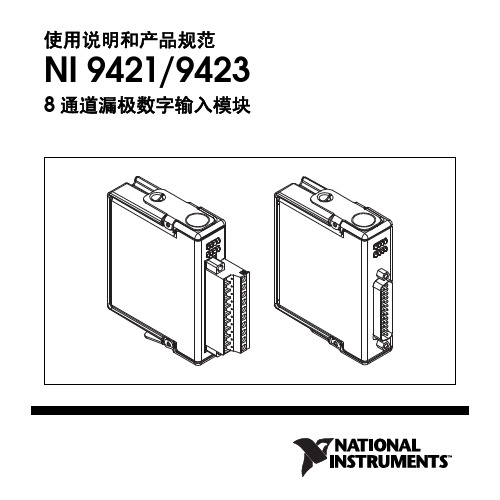
NI9421产品规范书
注意 电源未断开或处于危险环境时,请勿卸除模块。
注意 替换组件可能影响模块在环境等级为 Class I, Division 2 时的适用性。
注意 对于 Zone 2 环境中的应用,应将系统安装在 防护等级不低于 IP 54 (IEC 60529 和 EN 60529)的
NI 9421/9423 使用说明和产品规范
8
/china
+ 外部电源
–
漏极输出 设备 DI
COM
NI 9421/9423
图 3 连接设备至 NI 9421/9423 (图中为 3 线设备)
如源极输出设备在 DI 端加载的电流或电压在输入 ON 范围 内,则 NI 9421/9423 通道为 ON 状态。如设备在 DI 端加载 的电流或电压在输入 OFF 范围内,则 NI 9421/9423 通道为 OFF 状态。没有设备连接至 DI 时,通道为 OFF 状态。关于 ON 和 OFF 状态的详细信息见产品规范。
海事应用中的特殊要求
用于海事应用的模块必须通过劳氏船级社 (LR) 认证。如需了解 产品是否已通过 LR 认证,可访问 /certification 查询,或检查模块本身是否带有 LR 认证标记。
注意 为满足海事应用中对射频辐射的要求,应使用 屏蔽线缆并将系统置于金属外壳内。模块和控制器的 电源输入端必须安装抑制电磁干扰的磁箍。电源和模 块线缆必须位于外壳相对的的两侧,且进出外壳壁时 的方向相反。
图 1 为 NI 9932 连接器后壳示意图。
注 NI 9932 连接器后壳仅适用于螺栓端子接口的 NI 9421/9423。
图 1 NI 9932 连接器后壳
NI 9269 4通道模拟输入模块数据手册说明书
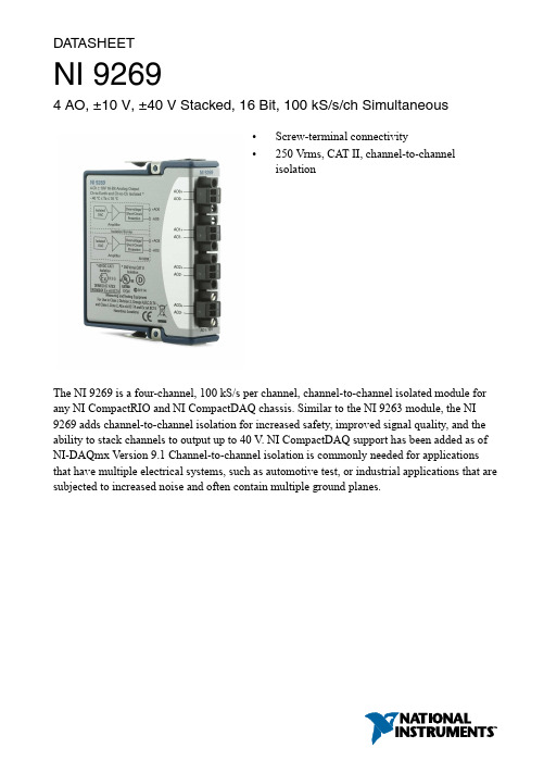
DAT ASHEETNI 92694 AO, ±10 V, ±40 V Stacked, 16 Bit, 100 kS/s/ch Simultaneous•Screw-terminal connectivity•250 Vrms, CAT II, channel-to-channelisolationThe NI 9269 is a four-channel, 100 kS/s per channel, channel-to-channel isolated module for any NI CompactRIO and NI CompactDAQ chassis. Similar to the NI 9263 module, the NI 9269 adds channel-to-channel isolation for increased safety, improved signal quality, and the ability to stack channels to output up to 40 V. NI CompactDAQ support has been added as of NI-DAQmx Version 9.1 Channel-to-channel isolation is commonly needed for applications that have multiple electrical systems, such as automotive test, or industrial applications that are subjected to increased noise and often contain multiple ground planes.Kit ContentsAccessories • NI 9269• NI 9269 Getting Started Guide• NI 9971 backshell kitNI C Series OverviewNI provides more than 100 C Series modules for measurement, control, and communication applications. C Series modules can connect to any sensor or bus and allow for high-accuracy measurements that meet the demands of advanced data acquisition and control applications.•Measurement-specific signal conditioning that connects to an array of sensors and signals •Isolation options such as bank-to-bank, channel-to-channel, and channel-to-earth ground •-40 °C to 70 °C temperature range to meet a variety of application and environmentalneeds •Hot-swappable2 | | NI 9269 DatasheetThe majority of C Series modules are supported in both CompactRIO and CompactDAQ platforms and you can move modules from one platform to the other with no modification. CompactRIOCompactRIO combines an open-embedded architecturewith small size, extreme ruggedness, and C Seriesmodules in a platform powered by the NI LabVIEWreconfigurable I/O (RIO) architecture. Each systemcontains an FPGA for custom timing, triggering, andprocessing with a wide array of available modular I/O tomeet any embedded application requirement. CompactDAQCompactDAQ is a portable, rugged data acquisition platformthat integrates connectivity, data acquisition, and signalconditioning into modular I/O for directly interfacing to anysensor or signal. Using CompactDAQ with LabVIEW, youcan easily customize how you acquire, analyze, visualize,and manage your measurement data.SoftwareLabVIEW Professional Development System for Windows•Use advanced software tools for large project development•Generate code automatically using DAQ Assistant and InstrumentI/O Assistant•Use advanced measurement analysis and digital signal processing•Take advantage of open connectivity with DLLs, ActiveX,and .NET objects•Build DLLs, executables, and MSI installersNI 9269 Datasheet| © National Instruments| 3NI LabVIEW FPGA Module•Design FPGA applications for NI RIO hardware•Program with the same graphical environment used for desktop andreal-time applications•Execute control algorithms with loop rates up to 300 MHz•Implement custom timing and triggering logic, digital protocols, andDSP algorithms•Incorporate existing HDL code and third-party IP including Xilinx IPgenerator functions•Purchase as part of the LabVIEW Embedded Control and MonitoringSuiteNI LabVIEW Real-Time Module•Design deterministic real-time applications with LabVIEWgraphical programming•Download to dedicated NI or third-party hardware for reliableexecution and a wide selection of I/O•Take advantage of built-in PID control, signal processing, andanalysis functions•Automatically take advantage of multicore CPUs or setprocessor affinity manually•Take advantage of real-time OS, development and debuggingsupport, and board support•Purchase individually or as part of a LabVIEW suite CircuitryThe analog output channels are floating with respect to earth ground and each other. Each channel has a digital-to-analog converter (DAC) that produces a voltage signal. Each channel 4| | NI 9269 Datasheetprovides an independent signal path, enabling you to update all four channels simultaneously. Each channel also has overvoltage and short-circuit protection.NI 9269 SpecificationsThe following specifications are typical for the range -40 °C to 70 °C unless otherwise noted. All voltages are relative to the AO- signal on each channel unless otherwise noted.Caution Do not operate the NI 9269 in a manner not specified in this document.Product misuse can result in a hazard. You can compromise the safety protectionbuilt into the product if the product is damaged in any way. If the product isdamaged, return it to NI for repair.Output CharacteristicsNumber of channels 4 analog output channelsDAC resolution16 bitsType of DAC R-2RPower-on output state High impedanceStartup voltage10 VPower-down output state2High impedanceOutput voltage range3Nominal±10 VMinimum±10.38 VTypical±10.47 VMaximum±10.56 VCurrent drive±20 mA all channels maximum;±10 mA per channel typicalOutput impedance100 mΩ1When the output stage powers on, a glitch occurs for 5 μs peaking at -900 mV.2When the module powers down, a glitch occurs for 20 μs peaking at -600 mV.3Refer to the device Getting Started Guide on /manuals for information about the stackednominal output voltage range and current drive.4Range equals 10.47 VNI 9269 Datasheet| © National Instruments| 5Table 1. AccuracyStabilityGain drift 5 ppm/°COffset drift80 μV/°CProtectionOvervoltage±30 VShort-circuit IndefinitelyNoise300 μVrmsSlew rate7 V/μsCrosstalkChannel-to-channel100 dBCommon-mode voltage120 dB5Uncalibrated accuracy refers to the accuracy achieved when acquiring in raw or unscaled modes where the calibration constants stored in the module are not applied to the data.6| | NI 9269 DatasheetSettling time100 pF load, to 1 LSBFull-scale step20 μs1 V step10 μs0.1 V step10 μs1 kΩ || 100 pF load, to 4 LSBFull-scale step20 μsCapacity drive1,500 pF maximumMonotonicity16 bitsDNL±1 LSB maximumINL (best fit)±2 LSBs maximumPower RequirementsPower consumption from chassisActive mode 1 W maximumSleep mode120 μW maximumThermal dissipation (at 70 °C)Active mode 1.4 W maximumSleep mode77 mW maximumPhysical CharacteristicsGauge0.05 mm to 1.5 mm (30 AWG to 14 AWG)copper conductor wireWire strip length 6 mm (0.24 in.) of insulation stripped from theendTemperature rating90 °C minimumTorque for screw terminals0.22 N · m to 0.25 N · m (1.95 lb · in. to2.21 lb · in.)NI 9269 Datasheet| © National Instruments| 7Wires per screw terminal One wire per screw terminal; two wires per screw terminal using a 2-wire ferrule Ferrules 0.25 mm 2 to 1.5 mm 2Connector securementSecurement type Screw flanges provided Torque for screw flanges 0.2 N · m (1.80 lb · in.)Weight156 g (5.5 oz)Safety VoltagesChannel-to-channelContinuous 250 Vrms, Measurement Category II Withstand 1,390 Vrms, verified by a 5 s dielectric withstand testChannel-to-earth groundContinuous 250 Vrms, Measurement Category II Withstand2,300 Vrms, verified by a 5 s dielectric withstand testDivision 2/Zone 2 hazardous locations applications (Channel-to-channel and channel-to-earth ground)60 VDC, Measurement Category I Measurement Category I is for measurements performed on circuits not directly connected to the electrical distribution system referred to as MAINS voltage. MAINS is a hazardous live electrical supply system that powers equipment. This category is for measurements of voltages from specially protected secondary circuits. Such voltage measurements include signal levels,special equipment, limited-energy parts of equipment, circuits powered by regulated low-voltage sources, and electronics.Caution Do not connect the NI 9269 to signals or use for measurements withinMeasurement Categories II, III, or IV.Note Measurement Categories CAT I and CAT O are equivalent. These test andmeasurement circuits are not intended for direct connection to the MAINS building installations of Measurement Categories CAT II, CAT III, or CAT IV.Measurement Category II is for measurements performed on circuits directly connected to the electrical distribution system. This category refers to local-level electrical distribution, such asthat provided by a standard wall outlet, for example, 115 V for U.S. or 230 V for Europe.Caution Do not connect the NI 9269 to signals or use for measurements withinMeasurement Categories III or IV .8 | | NI 9269 DatasheetHazardous LocationsU.S. (UL)Class I, Division 2, Groups A, B, C, D, T4;Class I, Zone 2, AEx nA IIC T4Canada (C-UL)Class I, Division 2, Groups A, B, C, D, T4;Class I, Zone 2, Ex nA IIC T4Europe (ATEX) and International (IECEx)Ex nA IIC T4 GcSafety and Hazardous Locations StandardsThis product is designed to meet the requirements of the following electrical equipment safety standards for measurement, control, and laboratory use:•IEC 61010-1, EN 61010-1•UL 61010-1, CSA 61010-1•EN 60079-0:2012, EN 60079-15:2010•IEC 60079-0: Ed 6, IEC 60079-15; Ed 4•UL 60079-0; Ed 5, UL 60079-15; Ed 3•CSA 60079-0:2011, CSA 60079-15:2012Note For UL and other safety certifications, refer to the product label or the OnlineProduct Certification section.Electromagnetic CompatibilityThis product meets the requirements of the following EMC standards for sensitive electrical equipment for measurement, control, and laboratory use:•EN 61326 (IEC 61326): Class A emissions; Industrial immunity•EN 55011 (CISPR 11): Group 1, Class A emissions•AS/NZS CISPR 11: Group 1, Class A emissions•FCC 47 CFR Part 15B: Class A emissions•ICES-001: Class A emissionsNote For the standards applied to assess the EMC of this product, refer to theOnline Product Certification section.CE ComplianceThis product meets the essential requirements of applicable European Directives, as follows:•2014/35/EU; Low-V oltage Directive (safety)•2014/30/EU; Electromagnetic Compatibility Directive (EMC)•94/9/EC; Potentially Explosive Atmospheres (ATEX)NI 9269 Datasheet| © National Instruments| 9Online Product CertificationRefer to the product Declaration of Conformity (DoC) for additional regulatory compliance information. To obtain product certifications and the DoC for this product, visit / certification, search by model number or product line, and click the appropriate link in the Certification column.Shock and VibrationTo meet these specifications, you must panel mount the system.Operating vibrationRandom (IEC 60068-2-64) 5 g rms, 10 Hz to 500 HzSinusoidal (IEC 60068-2-6) 5 g, 10 Hz to 500 HzOperating shock (IEC 60068-2-27)30 g, 11 ms half sine; 50 g, 3 ms half sine;18 shocks at 6 orientations EnvironmentalRefer to the manual for the chassis you are using for more information about meeting these specifications.-40 °C to 70 °COperating temperature(IEC 60068-2-1, IEC 60068-2-2)-40 °C to 85 °CStorage temperature(IEC 60068-2-1, IEC 60068-2-2)Ingress protection IP40Operating humidity (IEC 60068-2-78)10% RH to 90% RH, noncondensing Storage humidity (IEC 60068-2-78)5% RH to 95% RH, noncondensing Pollution Degree2Maximum altitude2,000 mIndoor use only.Environmental ManagementNI is committed to designing and manufacturing products in an environmentally responsible manner. NI recognizes that eliminating certain hazardous substances from our products is beneficial to the environment and to NI customers.For additional environmental information, refer to the Minimize Our Environmental Impact web page at /environment. This page contains the environmental regulations and directives with which NI complies, as well as other environmental information not included in this document.10| | NI 9269 DatasheetWaste Electrical and Electronic Equipment (WEEE) EU Customers At the end of the product life cycle, all NI products must bedisposed of according to local laws and regulations. For more information abouthow to recycle NI products in your region, visit /environment/weee.电子信息产品污染控制管理办法(中国RoHS)中国客户National Instruments符合中国电子信息产品中限制使用某些有害物质指令(RoHS)。
化工搪瓷设备技术参数及使用规范
化工搪瓷设备技术参数及使用规范
一、技术参数
1、不锈钢搪瓷设备结构
a)外壳:生产的外壳一般采用不锈钢SUS304,可选用SUS316L,搪瓷厚度为2-3mm。
b)总装:采用方形整体结构,坚固耐用,散发热量低,维护方便。
c)支架:使用耐高温金属材料精工细作,金属支架结实耐用,一次性投入资金少,支架自身不会发热,节省热量损失和能耗
2、不锈钢搪瓷设备功能参数
a)输入电压:AC220V;
b)输入频率:50Hz/60Hz;
c)输出电压:DC85-275V;
d)输出电流:2.1A;
e)最大功率:500W;
f)温控范围:0℃-400℃;
g)功率:450W;
h)精度:±2℃;
i)安全保护:具有过温保护、过流保护、超速保护等功能;
j)热控方式:温控;
k)温度传感器:NTC温度传感器。
二、使用规范
1、投入电源前应确认功率及输入电压是否符合要求,在投入电源前,应先检查连接线是否接好,电源检查完毕,可正式投入电源使用。
2、在使用不锈钢搪瓷设备前,应根据流程图设置加热时长、温度及
其他参数,这是非常重要的,加热温度过高可能会破坏搪瓷表面,过低又
可能会影响设备的使用效果。
国家仪器cRIO-9033嵌入式CompactRIO控制器产品规范说明书
产品规范NI cRIO-9033嵌入式CompactRIO 控制器,带实时处理器和可重配置FPGA本文档列出了National Instruments cRIO-9033的产品规范。
除非另外声明,否则下列规范的适用温度范围均为-40 °C ~ 70 °C。
警告 请勿尝试采用本文档中未提到的方式操作cRIO-9033。
错误操作设备可能发生危险。
设备损坏时,内部的安全保护机制也会受影响。
关于受损设备的维修事宜,请联系NI 。
处理器CPUIntel Atom E3825CPU 核的数量2CPU 频率 1.33 GHz L2缓存1 MB (共享)操作系统注: 请访问/info ,输入信息代码swsupport 了解最低软件支持信息。
支持的操作系统NI Linux Real-Time (64位)软件要求应用程序软件LabVIEWLabVIEW 2014或更高版本,LabVIEW Real-Time 模块2014或更高版本,LabVIEW FPGA 模块20141或更高版本用于NI Linux Real-Time 的C/C++ 开发工具2Eclipse Edition 2014或更高版本1 使用扫描接口模式时无需安装LabVIEW FPGA 模块。
如需在cRIO-9033 上对用户可访问的2用于 Linux Real-Time 的 C/C++开发工具是 cRIO-9033 处理器 C++编程的可选界面。
请访问/info ,并输入RIOCdev ,查看NI Linux Real-Time 上C/C++编程工具的详细信息。
FPGA 进行编程,需安装LabVIEW FPGA 模块。
驱动程序软件NI-RIO设备驱动程序2014年8月或更高版本网络/以太网端口端口数量2网络接口10Base-T, 100Base-TX, 1000Base-T Ethernet 兼容性IEEE 802.3通信速率10 Mbps, 100 Mbps, 1000 Mbps 自动调节线缆最大长度100 m/段RS-232串口最大波特率115,200 bps数据位5, 6, 7, 8停止位1, 2校验位奇、偶、标志、空格流控制RTS/CTS, XON/XOFF, DTR/DSRRI唤醒低电平(最大值)0.8 VRI唤醒高电平(最小值) 2.4 VRI过电压允许范围±24 VRS-485/422 (DTE)串口最大波特率115,200 bps数据位5, 6, 7, 8停止位1, 2校验位奇、偶、标志、空格流控制XON/XOFF2||NI cRIO-9033产品规范连线模式4线、2线、自动2线隔离电压60 VDC,连续,端口至大地注:RS-485串口地和屏蔽不连接至机箱地。
NI cRIO-9066 产品规范说明书
产品规范NI cRIO-9066用于C系列模块、带有可重配置FPGA的嵌入式实时控制器本文档列出了NI cRIO-9066的产品规范。
除非另外声明,否则下列规范的适用温度范围均为-20 °C~55 °C。
警告请勿尝试采用本文档中未提到的方式操作cRIO-9066。
错误操作设备可能发生危险。
设备损坏时,内部的安全保护机制也会受影响。
关于受损设备的维修事宜,请联系NI。
处理器类型Xilinx Zynq-7000、XC7Z020全可编程SoC 架构ARM Cotex-A9速度667 MHz内核数2闪存重启寿命1100,000个周期操作系统注:请访问/info,输入信息代码swsupport了解最低软件支持信息。
支持的操作系统NI Linux Real-Time (32-bit)软件要求应用程序软件LabVIEW LabVIEW 2014或更高版本,LabVIEW Real-Time模块2014或更高版本,LabVIEW FPGA模块2014或更高版本21对设备进行现场维护可延长闪存重启寿命。
如预计应用程序可能超出本文档中所列的最大周期数,请联系NI支持部门,了解如何延长重启寿命。
2使用扫描接口模式时无需安装LabVIEW FPGA模块。
如需在cRIO-9066上对用户可访问的FPGA进行编程,需安装LabVIEW FPGA模块。
驱动程序软件NI-RIO设备驱动程序14.0或更高版本内存非易失性内存3512 MB易失性内存(DRAM)256 MB网络网络接口10Base-T, 100Base-T, 1000Base-T Ethernet 兼容性IEEE 802.3通信速率10 Mbps/100 Mbps/1,000 Mbps,自动调节线缆最大长度100 m/段内部实时时钟精度 5 ppmUSB端口USB设备端口类型USB 2.0高速,带标准B型连接器最大数据速率480 MbpsUSB主机端口类型USB 2.0高速,带标准A型连接器最大数据速率480 Mbps可重配置FPGA类型Xilinx Zynq-7000、XC7Z020全可编程SoC 逻辑单元数85,000触发器数106,4006输入LUT数53,2003非易失性内存的格式化容量可能略低于该值。
使用石油产品抗乳化度仪安全操作规程模版(三篇)
使用石油产品抗乳化度仪安全操作规程模版第一章概述第1条为了提高石油产品抗乳化度仪的操作安全性,防止事故的发生,保障人身和设备的安全,制定本规程。
第2条本规程适用于石油产品抗乳化度仪的操作人员,相关工作人员必须按照本规程进行操作。
第二章操作安全第3条操作人员必须熟悉石油产品抗乳化度仪的结构和工作原理,并接受相关培训。
第4条操作人员应该佩戴合适的个人防护装备,在操作过程中必须戴好防护眼镜、穿戴防护手套,并穿戴专业工作服。
第5条在进行仪器操作前,操作人员必须仔细检查设备的各项指标,确保设备完好无损。
第6条在操作仪器时,操作人员应按照标准程序进行,不得在规定操作程序以外进行其他操作。
第7条在进行特定操作时,操作人员必须确保设备工作区域的安全,保持良好的通风条件。
第三章事故预防第8条操作人员在进行操作前,必须了解石油产品抗乳化度仪的工作环境,包括温度、湿度等条件。
第9条在操作过程中,如发现异常情况,操作人员必须立即停止操作,并向上级报告。
第10条操作人员在操作过程中,严禁使用电气设备或使用明火。
第11条操作人员在操作过程中,应当保持机器设备周围的清洁,避免积灰和杂物。
第12条操作人员在操作过程中,应当及时对仪器设备进行维护和保养,确保仪器设备的正常运行。
第四章紧急处理第13条在发生应急情况时,操作人员必须立即采取紧急措施,切断电源并立即向上级报告。
第14条在紧急情况下,操作人员必须按照应急预案进行处置,并确保自身及周围人员的安全。
第15条操作人员在紧急情况下,应当使用适当的消防设备进行灭火,切勿使用不符合要求的灭火器材。
第五章个人安全第16条操作人员必须按照石油产品抗乳化度仪的使用规范进行操作,切勿进行违规行为或超负荷操作。
第17条操作人员在操作过程中必须保持清醒状态,严禁酗酒、吸烟等不良习惯。
第18条操作人员在操作过程中,严禁随意离开或离岗,如有特殊情况必须由操作人员事先向上级报告。
第19条操作人员在操作过程中,应当遵守相关安全规定,禁止用手触摸仪器设备的电源线和内部元件。
NI-9263 4-Channel, ±10 V, 16-Bit Analog Voltage Ou
CALIBRATION PROCEDURENI-92634-Channel, ±10 V, 16-Bit Analog Voltage Output ModuleThis document contains the verification and adjustment procedures for the NI-9263. For more information on calibration solutions, visit /calibration.ContentsSoftware (1)Documentation (2)Test Equipment (3)Test Conditions (3)Initial Setup (3)Verification (4)Accuracy Verification (4)Adjustment (6)Accuracy Adjustment (6)EEPROM Update (6)Reverification (7)Accuracy Under Calibration Conditions (7)Worldwide Support and Services (8)SoftwareCalibrating the NI-9263 requires the installation of NI-DAQmx 9.6 or later on the calibration system. You can download NI-DAQmx from /downloads NI-DAQmx supports LabVIEW, LabWindows™/CVI™, ANSI C, and .NET. When you install NI-DAQmx, you only need to install support for the application software that you intend to use.2 | | NI 9263 Calibration ProcedureDocumentationConsult the following documents for information about the NI-9263, NI-DAQmx, and your application software. All documents are available on and help files install with the software.NI cDAQ-9174/9178 USB Chassis Quick Start NI-DAQmx installation and hardware setupNI-9263 Operating Instructions and SpecificationsNI-9263 specific information, specifications, and calibration intervalNI-DAQmx ReadmeOperating system and application software support in NI-DAQmxLabVIEW HelpLabVIEW programming concepts and reference information about NI-DAQmx VIs and functionsNI-DAQmx C Reference HelpReference information for NI-DAQmx C functions and NI-DAQmx C propertiesNI-DAQmx .NET Help Support for Visual StudioReference information for NI-DAQmx .NET methods and NI-DAQmx .NETproperties, key concepts, and a C enum to .NET enum mapping tableTest EquipmentNI recommends that you use equipment in Table 1 for calibrating the NI 9263. If the recommended equipment is not available, select a substitute using the requirementslisted in Table 1.Table 1. Recommended EquipmentEquipment Recommended Model RequirementsDMM NI 4070 DMM Use a multiranging 6 1/2 digitDMM with voltage measurementaccuracy of ±40 ppm.Chassis NI cDAQ-9178 — Connection Accessory NI 9932 —Test ConditionsThe following setup and environmental conditions are required to ensure the NI 9263 meets published specifications.•Keep connections to the NI-9263 as short as possible. Long cables and wires act as antennas, picking up extra noise that can affect measurements.•Verify that all connections to the NI-9263 are secure.•Use shielded copper wire for all cable connections to the NI-9263. Use twisted-pair wire to eliminate noise and thermal offsets.•Maintain an ambient temperature of 23 ± 5 °C. The NI-9263 board temperature will be greater than the ambient temperature.•Keep relative humidity below 80%.•Allow a warm-up time of at least 10 minutes to ensure that the NI-9263 measurement circuitry is at a stable operating temperature.Initial SetupComplete the following steps to set up the NI 9263.1.Install NI-DAQmx.2.Make sure that the NI cDAQ-9178 power source is not connected.3.Insert the module into slot 8 of the NI cDAQ-9178 chassis. Leave slots 1 through 7 of theNI cDAQ-9178 chassis empty.4.Connect the NI cDAQ-9178 chassis to your host computer.5.Connect the power source to the NI cDAQ-9178 chassis.unch Measurement & Automation Explorer (MAX).7.Right-click the device name and select Self-Test to ensure that the device is working properly.NI 9263 Calibration Procedure|© National Instruments Corporation| 34 | | NI 9263 Calibration ProcedureVerificationThe following performance verification procedure describes the sequence of operation and provides test points required to verify the NI 9263. The verification procedure assumes that adequate traceable uncertainties are available for the calibration references.Accuracy VerificationComplete the following procedure to determine the As-Found status of the NI 9263. 1. Set the DMM to Standby mode (STBY).2.Connect the DMM to the NI 9263 as shown in Figure 1.Figure 1. Accuracy Verification Connections3. Set the DMM to read DC voltage in the minimum range required to cover the NI 9263output range of ±10 V. 4.Acquire a sample a.Create and configure an AO voltage channel according to Table 2.Table 2. NI-9263 AO Voltage Channel ConfigurationInput RangeScaled UnitsTerminal ConfigurationMinMax-1010 Volts Single Endedb. Start the task.c.Generate a voltage output according to Table 3.Table 3. NI-9263 Output ConfigurationSamples Per ChannelTimeoutData110.0 A Test Point value indicated in Table 4.d. Wait the appropriate time for the DMM measurement to settle. e. Read the NI 9263 output voltage measurement from the DMM.f.Clear the task.NI 9263DMMpare the DMM measurement to the test limits in Table 4.6.Repeat steps 3 through 5 for each test point in Table 4.7.Disconnect the DMM from the NI 9263.8.Repeat steps 1 through 7 for each channel on the NI 9263.Table 4. NI 9263 Test LimitsRange (V) Test Point 1-Year LimitsMin Max Location Value (V)LowerLimit (V)UpperLimit (V)-10.000 10.000 Max 9.500000 9.482770 9.517230-10.000 10.000 Mid 0.000000 -0.009630 0.009630-10.000 10.000 Min -9.500000 -9.517230 -9.482770NI 9263 Calibration Procedure|© National Instruments Corporation| 5AdjustmentThe following performance adjustment procedure describes the sequence of operation required to adjust the NI-9263.Accuracy AdjustmentComplete the following procedure to adjust the accuracy performance of the NI-9263.1.Connect the DMM to the NI-9263 as shown in Figure 1.2.Adjust the NI-9263.a.Initialize a calibration session on the NI-9263. The default password is NI.b.Input the external temperature in degrees Celsius.c.Call the NI-9263 get C Series adjustment points function to obtain an array ofrecommended calibration voltages for the NI-9263.d.Set the DMM to read DC voltage in the minimum range required to cover the NI 9263output range of ±10 V.e.Call and configure the NI-9263 setup calibration function with the DAC valueobtained from the array of recommended calibration voltages.f.Wait the appropriate amount of time for the DMM measurement to settle.g.Read the NI-9263 output voltage measurement from the DMM.h.Call and configure the NI-9263 adjustment function according to Table 5.Table 5. Adjustment ConfigurationPhysical Channel Reference ValuecDAQMod8/ao x The NI-9263 output voltage measured from the DMM.i.Repeat steps e to h for each calibration voltage in the array.j.Close the calibration session.3.Disconnect the DMM from the NI-9263.4.Repeat step 1 for each channel on the NI-9263.EEPROM UpdateWhen an adjustment procedure is completed, the NI-9263 internal calibration memory (EEPROM) is immediately updated.If you do not want to perform an adjustment, you can update the calibration date and onboard calibration temperature without making any adjustments by initializing an external calibration, setting the C Series calibration temperature, and closing the external calibration.6||NI 9263 Calibration ProcedureReverificationRepeat the Verification section to determine the As-Left status of the device.Note If any test fails Reverification after performing an adjustment, verify that youhave met the Test Conditions before returning your device to NI. Refer to NI Servicesfor assistance in returning the device to NI.Accuracy Under Calibration ConditionsThe values in the following table are based on calibrated scaling coefficients, which are stored in the onboard EEPROM.The following accuracy table is valid for calibration under the following conditions: •Ambient temperature 23 °C ± 5 °C•NI-9263 installed in slot 8 of an NI cDAQ-9178 chassis•Slots 1 through 7 of the NI cDAQ-9178 chassis are emptyTable 6. NI-9263 AccuracyDevice Percent of Reading(Gain Error)Percent of Range*(Offset Error)NI-9263 0.08% 0.09%* Range equals 10.7 VNI 9263 Calibration Procedure|© National Instruments Corporation|7All rights reserved. NI ServicesVisit /support to find support resources including documentation, downloads, and troubleshooting and application development self-help such as tutorials and examples.Visit /services to learn about NI service offerings such as calibration options, repair, and replacement.Visit /register to register your NI product. Product registration facilitates technical support and ensures that you receive important information updates from NI.NI corporate headquarters is located at 11500 North Mopac Expressway, Austin, Texas, 78759-3504, USA.Information is subject to change without notice. Refer to the NI Trademarks and Logo Guidelines at /trademarks for more information on NI trademarks. Other product and company names mentioned herein are trademarks or trade names of their respective companies. For patents covering NI products/technology, refer to the appropriate location: Help»Patents in your software, the patents.txt file on yourmedia, or the National Instruments Patents Notice at /patents . You can find information about end-user license agreements (EULAs) and third-party legal notices in the readme file for your NI product. Refer to the Export Compliance Information at /legal/export-compliance for the NI global trade compliance policy and how to obtain relevant HTS codes, ECCNs, and other import/export data. NI MAKES NO EXPRESS OR IMPLIED WARRANTIES AS TO THE ACCURACY OF THE INFORMATION CONTAINED HEREIN AND SHALL NOT BE LIABLE FOR ANY ERRORS. U.S. Government Customers: The data contained in this manual was developed at private expense and is subject to the applicable limited rights and restricted data rights as set forth in FAR 52.227-14, DFAR 252.227-7014, and DFAR 252.227-7015. © 2006–2022 National Instruments Corporation. 372092D-01 2022-04-28。
康辉水硬度在线检测仪安全操作及保养规程
康辉水硬度在线检测仪安全操作及保养规程水硬度是人们生活中常见的问题,如果水中的硬度过高,就会对人体健康和管道设备造成很大的影响。
康辉水硬度在线检测仪是一种方便快捷的检测工具,为了保证检测仪的正常使用,我们需要遵守以下安全操作规程和保养规程。
安全操作规程1.使用前仔细阅读说明书,了解产品性能、操作流程及故障处理。
2.检测仪只适用于水处理行业,不能用于其他行业或领域。
3.检测仪需要插电使用,使用时必须接入接地插头。
4.操作时,要根据说明书指示正确接线,检测仪的电缆不可接反。
5.在使用前,要对检测仪进行严格的安装和调试,保证设备正常工作。
6.使用检测仪操作过程中,应注意不得将电缆与电容板弯曲、扭曲或拉长,以免影响测量精度。
7.检测仪的工作电压为24V DC,操作过程中不可接触电源线和电子元件,以免发生电击或器件损坏等危险。
8.检测仪操作完毕后,必须将电源线拔掉,切勿在点火或易燃物体附近存放或使用检测仪。
9.请勿拆卸检测仪内部部件,以免发生电击或其他不安全事件。
10.对于检测器出现故障或不能正常工作时,建议寄回维修站点进行修理,切勿擅自拆卸或修理。
保养规程1.使用时应保持水平状态,并放在干燥、通风、无易燃物,无腐蚀性气体的环境中,以防止检测仪被污染或受到侵蚀。
2.使用过程中要小心轻拿、轻放,以防止不必要的损坏。
3.经常对检测仪进行标准化测量,以保证检测仪的测量精度。
4.在使用检测仪之前,应对传感器进行清洗并校准。
清洗时不可使用酸性物质,只可使用苏打水进行清洗,以防止传感器被腐蚀。
5.在长时间停用检测仪时,应拆卸传感器进行清洗,保证传感器的使用寿命及测量精度。
6.检测仪需要经常进行检查和维护,并保证传感器总体干燥、清洁,不受污染或腐蚀。
7.当检测仪出现故障或不能正常工作时,建议寄回维修站点进行修理或更换,以保证检测仪正常、稳定工作。
总之,康辉水硬度在线检测仪是一款十分实用的水处理检测仪器,正确的使用和保养可以使其更好地发挥作用。
硝酸镍安全技术说明书中文
化学品安全技术说明书第1部分化学品及企业标识化学品中文名:硝酸镍(无水)化学品英文名:NICKEL NITRATE企业名称:此处填写贵公司名称企业地址:此处填写贵公司地址传真:此处填写贵公司传真联系电话:此处填写贵公司电话企业应急电话:此处填写贵公司应急电话产品推荐及限制用途:For industry use only.。
第2部分危险性概述紧急情况概述:可能加剧燃烧;氧化剂。
吞咽有害。
造成皮肤刺激。
造成严重眼损伤。
可能导致皮肤过敏反应。
吸入有害。
吸入可能导致过敏或哮喘病症状或呼吸困难。
怀疑会导致遗传性缺陷。
长期或反复接触会对器官造成伤害。
i。
D。
GHS危险性类别:氧化性固体类别 2急性经口毒性类别 4皮肤腐蚀/ 刺激类别 2严重眼损伤/ 眼刺激类别 1皮肤致敏物类别 1急性吸入毒性类别 4呼吸道致敏物类别 1生殖细胞致突变性类别 2特异性靶器官毒性反复接触类别 1危害水生环境——急性危险类别 1危害水生环境——长期危险类别 1致癌性类别1A生殖毒性类别1B标签要素:象形图:警示词:危险危险性说明:H272 可能加剧燃烧;氧化剂。
H302 吞咽有害。
H315 造成皮肤刺激。
H318 造成严重眼损伤。
H317 可能导致皮肤过敏反应。
H332 吸入有害。
H334 吸入可能导致过敏或哮喘病症状或呼吸困难。
H341 怀疑会导致遗传性缺陷。
H372 长期或反复接触会对器官造成伤害。
H410 对水生生物毒性极大并具有长期持续影响。
H350i 。
H360D 。
防范说明:•预防措施:•P210 远离热源/火花/明火/热表面。
禁止吸烟。
•P220 避开/贮存处远离服装/可燃材料。
•P280 戴防护手套/穿防护服/戴防护眼罩/戴防护面具。
•P264 作业后彻底清洗。
•P270 使用本产品时不要进食、饮水或吸烟。
•P261 避免吸入粉尘/烟/气体/烟雾/蒸气/喷雾。
•P272 受沾染的工作服不得带出工作场地。
•P271 只能在室外或通风良好处使用。
氨基磺酸验证、检验操作规程

验收指标:符合HG/T2527-93要求的工业优等品氨基磺酸的各项要求,公司对其主含量进行检测,主含量≥%为合格,重金属限量(以Pb计)≤%为合格。
验收方案:1 查进厂报告单,并与标准比较,报告单各项符合要求后,进行以下操作。
2氨基磺酸采样.验收方案按GB/T 6678-2003 中中的有关规定确定取样单元数,样品混匀后,平行测定三个主含量取其平均值,作为判断此产品的验收方案,即主含量≥% 判为合格;否则加倍采样,进行复检若仍不符合控制指标则视为该批原料不合格。
重金属限量每月第一批检测,重金属限量(以Pb计)≤%即为合格,否则加倍采样,进行复检若仍不符合控制指标则视为该批原料不合格。
1.检测:试剂氢氧化钠标准溶液:L 酚酞:10g/L含量测定称取0.2g氨基磺酸样品,精确至0.0002g于锥形烧杯中,加30毫升水,加2 滴酚酞指示剂,用氢氧化钠标准滴定液滴至微红色,保持30秒钟不褪色,既为终点。
计算v×c×x % = ———————× 100m ×1000x—氨基磺酸的质量百分含量,%v—氢氧化钠标准溶液之用量, mlc—氢氧化钠标准溶液之物质的量浓度, mol/Lm—样品的质量, g—氨基磺酸的摩尔质量,g/mol重金属限量检测依据GB/T 23950-2009无机化工产品中重金属测定通用方法每月一次双乙烯酮验收标准:本公司控制双乙烯酮进厂原料的主含量、乙酸酐二项技术指标,且要求主含量≥97%,Ace≤4%。
重金属限量(以Pb计)≤%为合格。
双乙烯酮采样方法供方以大容器(槽车)一次性装料时,采样方法按BG/T6680—《液体化工产品采样通则》,从排料口接收适量样品。
采样后,测其主含量与乙酸酐的指标,当主含量≥97%,乙酸酐≤4%时为合格;否则加倍采样,进行复检若仍不符合控制指标则视为该批原料不合格;重金属限量每月第一批检测,重金属限量(以Pb 计)≤%即为合格,否则加倍采样,进行复检若仍不符合控制指标则视为该批原料不合格。
- 1、下载文档前请自行甄别文档内容的完整性,平台不提供额外的编辑、内容补充、找答案等附加服务。
- 2、"仅部分预览"的文档,不可在线预览部分如存在完整性等问题,可反馈申请退款(可完整预览的文档不适用该条件!)。
- 3、如文档侵犯您的权益,请联系客服反馈,我们会尽快为您处理(人工客服工作时间:9:00-18:30)。
© National Instruments Corp.
11
NI 9263 使用说明和产品规范
产品规范
除非另外声明,否则下列规范的适用温度范围均为 –40 ~ 70 °C。所有电压均以 COM 端为参考地。
注 本文档中的安全守则和产品规范仅适用于 NI 9263。系统中其它组件的安全评级和产品规范可能 有所不同。 请参考系统中各个组件的说明文档,确定 整个系统的安全评级和产品规范。关于 C 系列模块 的说明文档,请访问 /info,输入信息代码 cseriesdoc 查询。
安全守则
请遵循 NI 9263 的使用说明。
NI 9263 使用说明和产品规范
14
/china
容性驱动....................................................1500 pF,最小值 单调性 ........................................................16 位 DNL..............................................................–1 ~ 2 LSB,最大值 INL (结束点)........................................16 LSB,最大值 MTBF............................................................25 °C 时,1732619 小时;
NI 9263 使用说明和产品规范
4
/c I/O 连线或连接器。
注意 电源未断开或处于非安全环境时,请勿卸除模 块。
注意 替换组件可能影响模块在环境等级为 Class I, Division 2 时的适用性。
注意 对于 Zone 2 环境中的应用,应将系统安装在 防护等级不低于 IP 54 (IEC 60529 和 EN 60529)的 外壳内。
使用说明和产品规范
NI 9263
4 通道, ±10 V, 16 位模拟电压输出模块
本文档主要介绍 NI 9263 的使用方法,及其产品规范和端子 分配。关于模块所需软件的详细信息,请访问 / info,输入信息代码 rdsoftwareversion 查询。欲知系 统安装、配置以及编程的相关信息,请参见系统文档。 关于 C 系列模块的说明文档,请访问 /info, 输入信息代码 cseriesdoc 查询。
AO0
0
COM
1
AO1
2
COM
3
AO2
4
COM
5
AO3
6
COM
7
NC
8
COM
9
图 2 NI 9263 端子说明
© National Instruments Corp.
7
NI 9263 使用说明和产品规范
NI 9263 每个通道带有一个 AO 端子,可连接负载正极。除每 个通道的公用端子 COM 外,连接器底部还有一个 COM 端 子。所有 COM 端子均内部连接至模块的隔离参考地。 NI 9263 连接负载时,负载正极连至 AO 端子,负载接地端 连至通道相应 COM 端子。图 3 为 NI 9263 连接负载的示意 图。
注意 为满足海事应用中对射频辐射的要求,应使用 屏蔽电缆并将系统置于金属外壳内。 模块和控制器的 电源输入端必须安装抑制电磁干扰的磁箍。 电源输入 电缆和模块输出电缆必须位于金属外壳上相对的两 侧。
NI 9263 使用说明和产品规范
6
/china
连接 NI 9263
NI 9263 带有 10 端子可拆卸式螺栓端子连接器,可连接 4 个 模拟输出通道。
AO
负载
NI 9263
COM
图 3 连接负载至 NI 9263
注 NI 9263 的某个端子连接多于一根导线时,请使 用 2 线金属套环确保安全连接。
NI 9263 使用说明和产品规范
8
/china
每个通道带有一个可生成电压信号的数模转换器 (DAC)。每 个通道均具有过压保护和短路保护功能。 关于过压保护和短
额定值.................................................±10 V 最小值.................................................±10.3 V 常规值.................................................±10.7 V 最大值.................................................±11 V 电流驱动能力..........................................±1 mA/ 通道,最大值 输出阻抗....................................................0.1 Ω
路保护的详细信息见产品规范。图 4 为 NI 9263 某一通道的 输出电路示意图。
隔离DAC
AO 过压/短路保护
NI 9263
放大器
COM
图 4 NI 9263 通道输出电路
模块上电时,通道输出启动电压。 关于启动电压的详细信息 见产品规范。 关于在软件中配置启动输出状态的详细信息, 见软件帮助文档。
© National Instruments Corp.
9
NI 9263 使用说明和产品规范
高频振动应用中的连线
在高频振动应用中使用 NI 9263 时, NI 建议使用金属套环固 定可拆卸式螺栓端子连接器的连线,或使用 NI 9932 后壳套 件保护连线。图 5 为使用金属套环的示意图。图 1 为 NI 9932 连接器后壳示意图。
© National Instruments Corp.
5
NI 9263 使用说明和产品规范
海事应用中的特殊要求 用于海事应用的模块必须通过劳氏船级社 (LR) 认证。 如需了解模块是否已通过 LR 认证,可访问 / certification 查询,或检查模块本身是否带有 LR 认证标记。
NI 9263 使用说明和产品规范
12
/china
精度
测量条件
已校准,最大值 (–40 ~ 70 °C)
已校准,常规值 (25 °C, ±5 °C)
未校准,最大值 (–40 ~ 70 °C)
未校准,常规值 (25 °C, ±5 °C)
* 量程为 ±10.7 V
读数百分比 (增益误差)
0.35%
注意 请勿将危险电压电路与安全电路放置在同一模 块内。
注意 确保人体与设备及连至该模块的电路有效隔 离。
注意 模块端子接通危险电压 (>42.4 Vpk/60 VDC) 时,应确保人体与设备及连至该模块的电路有效隔 离。此时必须使用 NI 9932 连接器后壳套件,避免人 体与端子意外接触。
© National Instruments Corp.
输出特性
通道数 ........................................................4 个模拟输出通道 DAC 精度 ..................................................16 位 DAC 类型 .................................................. 字符串 上电输出状态.......................................... 通道断开 启动 / 掉电电压......................................0 V 输出电压量程
串扰 .............................................................76 dB 稳定时间 (100 pF 负载,至 1 LSB)
全量程变化 .......................................20 μs 3 V 变化 .............................................10 μs 0.1 V 变化..........................................8 μs 毛刺能量 (256 个变化,最差情况)................2 mV, 2 μs
保护 过压......................................................±30 V 短路...................................................... 无穷
© National Instruments Corp.
0.01%
2.2%
0.3%
量程百分比 * (偏置误差)
0.75%
0.1%
1.7%
0.25%
稳定性 增益漂移............................................6 ppm/°C 电压漂移............................................80 μV/°C
图 5 10 端子可拆卸式螺栓端子连接器,带金属套环
NI 9263 使用说明和产品规范
10
/china
休眠模式
模块支持低功耗休眠模式。 系统是否支持休眠模式取决于模 块所在的机箱。 关于系统是否支持休眠模式的详细信息,见 机箱文档。 关于启用休眠模式的详细信息,见软件帮助文 档。关于 C 系列模块的说明文档,请访问 /info, 输入信息代码 cseriesdoc 查询。
