PL34220191000DXED中文资料
MCP3421模数18位高精密△-∑A/D转换器及其应用

18位高精密转换器MCP3421及其应用Microchip公司的MCP3421与其他A/D转换器相比,特点主要表现在:全差分输入;1 8位分辨率;精密的连续自校准功能;可选择3.75、15、60或240 sps采样速率进行转换;可工作在连续转换或单次转换模式,在单次转换后的空闲期内自动进入待机模式,极大地减小了电流消耗;内部集成2.048 V±0.05%精度,且温度漂移仅为5ppm/℃的基准电压源;可编程增益放大器(PGA)提供1/2/4/8倍增益,允许测量极小的信号并且具有很高的分辨率;内部集成振荡器电路并提供I2 C串行接口等。
1 MCP3421封装形式与结构MCP3421是Microchip公司△-∑A/D转换器系列的一款18位分辨率器件,采用SOT23-6封装。
图1为MCP342引脚分布图,各引脚的功能如表1所列。
MCP342内部采用了Microchip专利的差分开关电容△-∑转换及数字滤波技术,专为需要高分辨率和低功耗的应用而设计。
在这种应用中,空间和低功耗是设计的首要考虑因素。
MCP3421可在2.7~5.5V单电源下电压工作,并消耗很低的电流。
在VDD=3 V、单次转换、1 sps条件下,电流消耗仅为39μA(典型值)。
其内部功能框图略--编者注。
2 MCP3421的工作原理MCP3421为一个全差分、18位分辨率且具有自校正功能的△-∑A/D转换器,内部内部包括△-EA/D转换器、可编程增益放大器(PGA)、时钟振荡器和I2C串行接口,以及2.048 V电压基准源5部分。
MCP3421设计简单、极易配置,允许设计工程师通过最小配置获得精确的测量结果。
2.1 △-∑A/D转换器MCP3421△-∑A/D转换器包括一个差分开-关电容△-∑调制器和一个数字滤波器。
调制器测量差分模拟输入电压(经内部PGA放大),并将其与内部电压基准相比较。
MCP3421内部集成了2. 048 V电压基准。
ADP3421笔记本电脑CPU供电芯片引脚功能

ADP3421是笔记本电脑主板上常用的电源管理芯片,如IBM的T20,T21,T22,A系列笔记本电源控制芯片均采用ADP3421,该芯片通常与ADP3410搭配使用. [1]~o/e0笔记本电脑中的ADP3421芯片很容易损坏,通常表现为莫命其妙地死机,开机后不定期掉电或开机时根本无法加电等现像. (BfyHuL9' M1VHYS核心电压滞后比例设置端 ;Q8[1]rAsf 92CLSET电流限制设置端 _i&awm/ U3LTO标准译码输出端,该脚电压不能低于1.5VD)LqkfJ}z^4LTI标准译码输入端 aSNTm8SY X5LTB标准译码电路偏置电压输入端 Kd,7x'h`E6VID4 `Df)wNN17VID3 !Zf)N_k8VID2CPU电压模式识别端 7b[vZNi_9VID1 s@bo df&10VID0 )0Lv-?Gs[1]11CLKDRV2.5V线性稳压电源驱动信号输出端 E%C 02sI12CLKFB2.5V线性稳定电源反馈端 \ lpR+zaF13IODRV1.5V线性稳压电源驱动信号输出端 8MPXrc,9-14IOFB1.5V线性稳压电源反馈端 0/Ju sQ15SD待机控制端,该脚为低电平时电路停止工作 B?J#NFUb16PWRGDPOWERGOOD监视信号输出端 m4 8m 5>17UVLO欠压检测端 %t^-G?uz18SSL线性稳压器软启动控制端 `!\`yI$!%w19SSC核心电压软启动控制端 f#UT~/~bL220CORE核心电压镜像检测输出端 m[FH >21DACOUTDAC数字信号输出端 RcH",*U22GND地 7Z/KXc[b23OUT核心电压驱动信号输出端 { ?' DZR s24VCC供电端 C. H r25RAMP电流斜率输入端,该端是核心输出电压的反相反馈输入端 0x\b[1]DWZ_26REG基准电压输出端 iIoeG_^*Y27CS+电流限制正相检测输入端 C-a bc +/28CS-电流限制反相检测输入端 b*xw=G3%ADP3421损坏 IBM A21M不工作机器型号:IBM A21M故障现象:按下开机键,电源指示灯闪一下即灭,机器不工作。
PL34220191000CDED中文资料
PL340, 341, 342
Vishay Thin Film
Plastic Leadless Chip Carrier
TURES
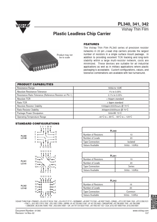
The Vishay Thin Film PL340 series of precision resistor networks in 20 pin J-lead chip carriers provide the largest number of resistors in a single surface mount package. In addition to providing excellent TCR tracking and long-term stability within a large multi-resistor network, costs are minimized. These devices are suitable for all industrial applications as well as in military applications where plastic packaging is acceptable. Custom configurations, values, and tolerance combinations are available with fast turnaround.
PL341 LC141
PL342 Number of Resistors Number of Leads Type Connection Values Available 19 20 Common 500Ω - 100KΩ
PL342 LC142
PACKAGED PRODUCTS NETWORKS
29400资料
PRELIMINARY
(February, 2001, Version 0.1)
1
AMIC Technology, Inc.
元器件交易Hale Waihona Puke
A29400 Series
The host system can detect whether a program or erase operation is complete by reading the I/O7 ( Data Polling) and I/O6 (toggle) status bits. After a program or erase cycle has been completed, the device is ready to read array data or accept another command. The sector erase architecture allows memory sectors to be erased and reprogrammed without affecting the data contents of other sectors. The A29400 is fully erased when shipped from the factory. The hardware sector protection feature disables operations for both program and erase in any combination of the sectors of memory. This can be achieved via programming equipment. The Erase Suspend feature enables the user to put erase on hold for any period of time to read data from, or program data to, any other sector that is not selected for erasure. True background erase can thus be achieved. Power consumption is greatly reduced when the device is placed in the standby mode. The hardware RESET pin terminates any operation in progress and resets the internal state machine to reading array data.
2010_PL系列功放中英文说明书BM049-0

一、注意事项()Cautions 内部有危险电压,触及会有触电危险设备进行操作维修,注意安全q 不要在功放上堆放物件。
q 使用一个大的容量的电源插座进行供电是必要的。
q 输入电平由各自通道的增益电位进行调整。
q 使用立体声,桥接单声道,单声道同相输入时,输出的连接方法要与册模式开关所对应的模式一样。
q 当连接输出大功率,功放发热时,风扇的转速增加,机箱内会发出轻微的噪声,这是正常的。
q 机后板通风槽不能有任何阻塞.清洁机箱时,先关机拔下后面的电源插头后,使用干燥的布进行擦洗。
q 本机不能与水接触。
q 如果功放出现异常,应及时关机,拔下电源插头与经销商联系。
Internal Dangerous Voltage of the product. Do not touch it,It can cause electric shock .The systemt is under operation and maintenance, Be safety.(Power Off before clearing the case.)(Do not put anything onto this amplifier.)(Huge Power Supply is needed .)(Input Level is adjusted by Gain Potential of Each Channal .)(Use Stereo ,Bridges Mono Channel.)(Some Noise from Radiator Fan is normal.)(No any obstruction in the ventilated groove in the rear panel.)(Do not access to water.)九、Specification 技术参数()二、Features 功能特点()►宽电压适应范围和稳定可靠的性能(Wide voltage range,Stable and dependable performance )相对于额定输入电源电压,有65%~130%的超宽工作电压范围设计,因此极强的电压波动环境均能轻松应对.同时开机音量渐变电路更多的考虑了现场观众的感受.先进的SMT贴片工艺更为稳定性能保驾护航.(65% ~ 130% the extra wide working voltage range design against the relative rated Input supply voltage , so it can easlily cope with the strong voltage fluctuation environment.Meanwhile, power volume gradient circuit more considered the audience feelings. Advanced SMT technology make the performance more stable. )►精确,纯净的音质特性和极好的信噪比()Precise and pure quality and wonderful SNR 为了消除声音缺陷进行了大量的试验投入工作终于有了回报,因而精确和透亮是PL7系列的显著特征.而同样出色的还有PL7系列超低的失真值和极好的信噪比(Finally, several experiments to eliminate the sound defaults are paid. Consequently, precision and clearity of PL7 series are remarkable. Let alone the ultra-low distortion and super S/N R. )►灵活功率设置和通用输入输出接口()Flexible power set 得益于它独特灵活的功率系统,MA功放可以在各种音箱之间方便连接,包括有一个超大容量的功率储备,以及可以运行于立体声,单声道,桥接工作模式的能力.(The unique and flexible power system, PL7, helps with a huge capacity storage. It can be connected with all kinds of speakers. What’s more, MA functions well in the circumstances of stereo, single channel and bridge connection models.)►为专业安装,剧院以及现场扩声等更多的应用而设计(professional equipments,theatres and live amplifying .)Designed for the applications of轻巧的2U机箱设计更适合搬运和安装,同时适合所有机柜中任何一个位置安装成了它的又一亮点.所有完善的保护电路使其具备航空母舰般的自我保护特性.同时面板的多方位保护更显设计的人性化(The handy 2U-cabinet that makes setting and carrying easier can be fixed on any parts of the rack. The perfect protection circuit makes its self-protected characteristics are as splendid as the aircraft carrier’s.)►全智能动态压限系统和失真消除电路(eliminate circuit )Totally intelligent dynamic limiter system and distortion专利技术的动态压限控制功率电路,保护系统始终处于安全工作状态.同时专用失真消除电路保证功放在任何状态均处在最小失真状态.(The circuit which power is controlled by dynamic limiter is a patent, assuring the system is working in a permanent safe situation.)►专利的接地技术极大方便系统连接()Patent of earthed technology PL7系列采用最新专利接地技术,可省掉浮地开关,而在任何的连接方式时噪声都是最小的.给系统连接带来极大的方便。
Keysight Technologies P-Series Power Meters and P-
Keysight TechnologiesP-Series Power Meters andP-Series Wideband Power SensorsConfiguration GuideP-Series Power Meters:N1911A Power Meter (single channel)N1912A Power Meter (dual channel)P-Series Power Sensors:N1921A Power Sensor (50 MHz to 18 GHz)N1922A Power Sensor (50 MHz to 40 GHz)IntroductionThis configuration guide describes standard configurations, options and compatible accessories. Contact your local Keysight Technologies, Inc. representative for additional information.P-Series Power MetersThe P-Series power meters provide peak, average, peak-to-average ratio power measurements, time-gated and free run modes, rise time, fall time and pulse width measurements.The P-Series power meters are compatible with the 8480, E-Series and new P-Series power sensors. The P-Series power meters have a different sensor input connector than the EPM and EPM-P Series power meters, so it is necessary to use adapter cables. These adapter cables come in three different lengths. When using the 8480 or E-Series sensors, refer to the Cable Accessories section in this guide. For additional information, refer to the Literature References section.The standard P-Series power meters include:–Single-channel power meter, order N1911A or dual-channel power meter, order N1912A–Input sensor connector(s) on the front panel–Reference calibrator (1 mW, 50 MHz) connector on the front panel–Documentation CD-ROM–Keysight Instrument Control DVD–IO libraries suite–Command expert–BenchVue software platform–30-day free trial of BenchVue power meter/sensor control and analysis app–Supplied accessories: power cord (plug matches country destination requirements)–USB adapter cable (part number 8121-1583, Cable-Assembly 4Pin-5Pin Male USB 2000 mm-LG)P-Series Wideband Power SensorsThe P-Series wideband power sensors are designed specifically for operation with the P-Series power meters for wide bandwidth power and time measurements. These sensors are the only Keysight power sensors that have their cable permanently wired (hard-wired) into the sensor. This provides better wide bandwidth specifications compared to having a removable cable. Refer to the Sensor Cable Lengths section in this guide for part number and cable length information.The standard P-Series power sensors include:–Power sensor 50 MHz to 18 GHz, order N1921A–Power sensor 50 MHz to 40 GHz, order N1922A–Documentation CD-ROM1. The Installation Guide is in English, French, and Japanese languages (part number N1912-90009).CompatibilityPower sensor compatibilityThe P-Series power meters are compatible with all current (N)8480, E-Series andP-Series power sensors. Refer to the Accessories section, P-Series meter cable adaptorsN1917A/B and C.Connector options for P-Series power metersThe following options are available on the P-Series power meters. 1Table 1. Connector options for P-Series power meters.Option DescriptionN1911A-003Rear panel sensor and power reference connectors (single channel)N1912A-003Rear panel sensor and power reference connectors (dual channel)Video output option (H01)The video output provides a DC voltage proportional to the measured input power through a BNC connector on the rear panel. The DC voltage can be displayed on an oscilloscope for time measurement. This option replaces the recorder output on the rear panel. The video output impedance is 50 Ω.–Video rise time: 13 ns–Frequency range: 50 MHz to 40 GHz 21. The P-Series power meters are configured for either front panel connectors (both sensor and powerreference) or rear panel connectors. There are no options for parallel front and rear panel sensor inputs.2. Need to turn off the auto-zero feature; otherwise, this will appear as a glitch in the video output signal.P-Series Power Meter Optional AccessoriesTable 2. P-Series power meter optional accessories.Accessory part number DescriptionN1911A-908N1912A-908Rack mount kit (one instrument)N1911A-909N1912A-909Rack mount kit (two instruments)34131A Basic instrument transit case 34161AAccessory pouchSoftware AccessoriesKeysight BenchVue softwareKeysight BenchVue software for the PC accelerates testing by providing intuitive, multiple instrument measurement visibility and data capture with no programming necessary. You can derive answers faster than ever by easily viewing, capturing and exporting measurement data and screen shots. The N1911A/12A Power Meters are supported by Keysight BenchVue software’s BV0007B Power Meter/Sensor Control and Analysis app.For more information, /find/BenchVueCable AccessoriesPower sensor adapters for use with 8480 and E-Series power sensors:Table 3. Cable accessories for use with 8480 and E-Series power sensors.Accessory part number DescriptionN1917A P-Series meter cable adaptor, 1.5 m (5 ft)N1917B P-Series meter cable adaptor, 3 m (10 ft)N1917CP-Series meter cable adaptor, 10 m (31 ft)P-Series Wideband Power Sensor Cable LengthsThree fixed cable length options are available for the P-Series power sensors at 1.5 m, 3.0 m and 10 m. Option 105 is the standard (default) option.Table 4. P-Series wideband power sensor cable lengths.OptionDescriptionN1921A-105N1922A-105Fixed 1.5 m (5 ft) cable length N1921A-106N1922A-106Fixed 3 m (10 ft) cable length N1921A-107N1922A-107Fixed 10 m (31 ft) cable lengthCalibration OptionThe P-Series power meters and sensors are available with Option 1A7 (ISO17025 compliant calibration) or Option A6J (ANSI Z540 compliant calibration).DocumentationThe P-Series power meters are supplied with a Product Reference CD which contains the installation guide, user’s guide, programing guide and service guide User’s Guide Programming Guide. The following tables supply the option number as well as the Keysight part number (where appropriate) to order the documentation.Table 5. Documentation.Option DescriptionN1911A-0BK N1912A-0BK Additional English language manual set (User’s Guide, part number N1912-90002 and Programming Guide part number N1912-90009)N1911A-0BFN1912A-0BFEnglish-language Programming Guide (part number N1912-90009)N1911A-0BWN1912A-0BWService Guide (part number N1912-90015)N1911A-ABJN1912A-ABJJapanese localization, User’s Guide part number N1912-90007N1921A-0B1 N1922A-0B1Additional English language manual set, Operating and Service Manual, part number N1920-90007Literature ReferencesPublication title Publication number P-Series Power Meters and P-Series Wideband Power Sensors – Technical Overview5989-1049ENN1911A/N1912A P-Series Power Meters and N1921A/N1922A Wideband PowerSensors - Data Sheet5989-2471ENE4416A/E4417A EPM-P Series Power Meters and E-Series E9320 Peak and AveragePower Sensors – Data Sheet5980-1469E EPM Series Power Meters E-Series and 8480 Series Power Sensors - Data Sheet5965-6382E Fundamentals of RF and Microwave Power Measurements (Part 1) - Application Note5988-9213EN Fundamentals of RF and Microwave Power Measurements (Part 2) - Application Note5988-9214EN Fundamentals of RF and Microwave Power Measurements (Part 3) - Application Note5988-9215EN Fundamentals of RF and Microwave Power Measurements (Part 4) - Application Note5988-9216EN4 Steps for Making Better Power Measurements - Application Note5965-8167E Choosing the Right Power Meter and Sensor - Application Note5968-7150EThis information is subject to change without notice.© Keysight Technologies, 2009 - 2018Published in USA, March 7, 20185989-1252ENLearn more at/find/software Start with a 30-day free trial./find/free_trialsDownload your next insightKeysight software is downloadableexpertise. From first simulation through first customer shipment, we deliver the tools your team needs to accelerate from data to information to actionable insight. – Electronic design automation (EDA) software– Application software– Programming environments –Productivity softwareEvolving Since 1939Our unique combination of hardware, software, services, and people can help you reach your next breakthrough. We are unlocking the future of technology.From Hewlett-Packard to Agilent to Keysight.myKeysight/find/mykeysightA personalized view into the information most relevant to you./find/emt_product_registrationRegister your products to get up-to-date product information and find warranty information.Keysight Channel Partners/find/channelpartnersGet the best of both worlds: Keysight’s measurement expertise and product breadth, combined with channel partner /find/powermetersFor more information on KeysightTechnologies’ products, applications or services, please contact your local Keysight office. The complete list is available at:/find/contactus Americas Canada (877) 894 4414Brazil 55 11 3351 7010Mexico001 800 254 2440United States(800) 829 4444Asia Pacific Australia 1 800 629 485China800 810 0189Hong Kong 800 938 693India 1 800 11 2626Japan 0120 (421) 345Korea 080 769 0800Malaysia 1 800 888 848Singapore 180****8100Taiwan0800 047 866Other AP Countries (65) 6375 8100Europe & Middle East Austria 0800 001122Belgium 0800 58580Finland 0800 523252France 0805 980333Germany ***********Ireland 1800 832700Israel 1 809 343051Italy800 599100Luxembourg +32 800 58580Netherlands 0800 0233200Russia 8800 5009286Spain 800 000154Sweden 0200 882255Switzerland0800 805353Opt. 1 (DE)Opt. 2 (FR)Opt. 3 (IT)United Kingdom0800 0260637For other unlisted countries:/find/contactus (BP-9-7-17)。
AH342-PL-B;中文规格书,Datasheet资料

HALL-EFFECT LATCHLead-free•Digital dual complementary sink/source outputs•Reverse Voltage Polarity protection for full supplyrange.•High output current capability•Low profile packages: SIP-4L•Lead Free Package: SIP-4L•Lead Free Finish/RoHS Compliant (Note 1)The AH342 is a bipolar latching hall IC with a pair ofcomplementary push/pull outputs. A dual hall element is used tooffset stress induced noise and drift. The robust outputs arecapable of sourcing up to 7.4mA and sinking up to 4.4mA. Thedevice contains inherent reverse polarity protection up to the fullpower supply range.• Conveyors• Motorcontrol• Powersensing•Linear or rotary motion detection• RPMsensingAH 342 - P L - BP : SIP-4LPackage Lead FreeL : Lead FreePackingB : BulkDevicePackageCodePackaging(Note 2)BulkQuantity Part Number Suffix AH342-PL-B P SIP-4L 1000 -B Notes: 1. EU Directive 2002/95/EC (RoHS). All applicable RoHS exemptions applied. Please visit our website at/products/lead_free.html.2. Pad layout as shown on Diodes Inc. suggested pad layout document AP02001, which can be found on our website at/datasheets/ap02001.pdf.Features General DescriptionApplicationsOrdering InformationHALL-EFFECT LATCHPin Assignments( Top View )1 : Vcc2 : DO3 : DOB4 : VssSIP-4LPin DescriptionsPin Name DescriptionSupplyV CC PositivePowerpinDO OutputpinDOB OutputV SS GroundConnectNC NoHALL-EFFECT LATCHBlock DiagramI OIO 1IO 2Absolute Maximum Ratings (Note 3)SymbolCharacteristicsConditionsRatingUnitV CC Supply voltage -40o C to 125o C ±28 VV OUT Voltage Externally Applied to Output -40o C to 125o C -1.2 to 5 V Ic Output Current ±10 mA B Magnetic Flux density No limit; the circuit cannot bedamaged by magnetic overdrive UnlimitedT STStorage TemperatureNo power applied -40 to 150 °CNotes: 3. Absolute maximum ratings are the extreme limits that the device will withstand without damage to the device. However, the electrical andmagnetic characteristics are not guaranteed as the maximum limits (above recommended operating conditions) are approached nor will the device necessarily operate at absolute maximum rating.HALL-EFFECT LATCHRecommended Operating ConditionsSymbolCharacteristicConditionsMinMaxUnit V CC Supply VoltageOperating4.5 28VT AOperating AmbientTemperature (Note 4) Operating -40 125 °CNotes: 4. Shall not exceed P D and Safety Operation Area.Electrical Characteristics (Note 5, 6)Symbol Characteristic Conditions24o C ± 2o C -40o C to 125o CUnitsMin Typ.Max Min Typ. Max I CCSupply Current28V±0.5% supply44.5634.57mAOutput VoltageV OUT #1 Sourcing Switch magnetically operated:No load 28V±0.5% supply. Switch magnetically released: No load 28V±0.5% supply.6.07.0 7.5 - - - V#2 Sinking0 0.1 0.2 - - - #1 Sinking 0 0.1 0.2 - - - #2 Sourcing6.07.07.5---I Leak(sink) Leakage (sink)Apply voltage 0.2V greater thanmeasured output source voltagemeasure current, no load 28V±0.5% supply.- - 1.0 - - 1.0µA Output CurrentI OUT#1 SourcingApply 2V to output and measure current. Switch magneticallyoperated, no load 28V±0.5%. Apply 2V to output and measurecurrent. Switch magneticallyreleased, no load 28V±0.5%. 5.5 7.4 8.0 5.0 7.4 8.5mA#2 Sinking2.83.44.7 2.4 3.45.0#1 Sinking2.83.44.7 2.4 3.45.0#2 Sourcing 5.5 7.4 8.0 5.0 7.4 8.5Output Switching Timetf Fall Time90% to 10%; no load 28V±0.5%Supply- - - - - 1.0µstr Rise Time10% to 90%; no load 28V±0.5%Supply - - - - - 1.0HALL-EFFECT LATCHMagnetic Characteristics (T A = +25°C) (Note 5, 6)( 1mT = 10 Gauss )Symbol Characteristic24o C ±2o CVs=12Vdc ± 0.5%Vdc-40o C to 125 o CVs=4.5Vdc to 28Vdc Unit Min Max MinMax Bop OperatePoint 4012030150 Gauss Brp ReleasePoint -120-40-150-30Gauss Bhy Hysteresis 120 200 120 200Gauss Notes: 5. All the parameters are tested under the 25o C only. The operation temperature (-40o C to 125o C) is guaranteed by design, it is typical value.6.The magnetic field strength (gauss) required to cause the switch to change state (operate and release) will be as specified in the magneticcharacteristics. To test the switch against the specified magnetic characteristics the switch must be placed in a uniform magnetic field.rp opN( Magnetic flux density B )DOrp opN( Magnetic flux density B )DOBPerformance CharacteristicsT A (°C) 25 50 60 70 80 85 90 95 100P D(mW)550 440 396 352 308 286 264 242 220 T A (°C) 105 110 115 120 125 130 135 140 150P D (mW) 198176154132110886644HALL-EFFECT LATCHOperating CharacteristicsrpopN( Magnetic flux density )( SIP-4L)Marking Information( Top View )X : Internal Code : a~z : Lead FreeY : Year : 0~9WW : Week : 01~52, "52" represents 52 and 53 weekHALL-EFFECT LATCHPackage Information (All Dimensions in mm)(1) Package type: SIP-4LActive Area DepthSensor Location1.1士Package DimensionHALL-EFFECT LATCHIMPORTANT NOTICELIFE SUPPORTDiodes Incorporated and its subsidiaries reserve the right to make modifications, enhancements, improvements, corrections or other changes without further notice to any product herein. Diodes Incorporated does not assume any liability arising out of the application or use of any product described herein; neither does it convey any license under its patent rights, nor the rights of others. The user of products in such applications shall assume all risks of such use and will agree to hold Diodes Incorporated and all the companies whose products are represented on our website, harmless against all damages.Diodes Incorporated products are not authorized for use as critical components in life support devices or systems without the expressed written approval of the President of Diodes Incorporated.分销商库存信息: DIODESAH342-PL-B。
MCP3421中文数据手册
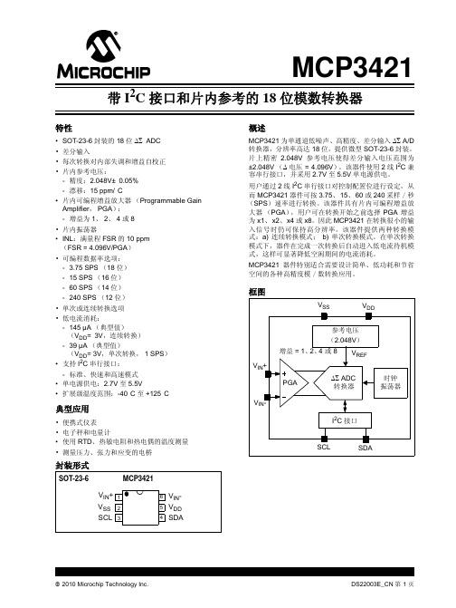
注:除非另外声明,否则 TA = -40°C 至 +85°C, VDD = +5.0V, VSS = 0V, VIN+ = VIN- = VREF/2。
Integral Nonlinearity (% of FSR)
VOS
— — — — — —
VDD IDDA IDDS VIH VIL VOL VHYST IDDB IILH IILL
2.7 — — — 0.7 VDD — — 0.05VDD — — -1 —
— 155 145 0.1 — — — — — — — —
5.5 190 — 0.5 VDD 0.3VDD 0.4 — 10 1 — 10
2010 Microchip Technology Inc.
DS22003E_CN 第 3 页
MCP3421
电气特性 (续)
电气规范:除非另外说明,否则所有参数的适用条件为:TA = -40°C 至 +85°C, VDD = +5.0V, VSS = 0V, VIN+ = VIN- = VREF/2。 所有 ppm 单位使用的满量程为 2*VREF。 参数 增益误差 (注 5) PGA 增益误差匹配 (注 5) 增益误差偏移 (注 5) 失调误差 失调漂移 — 温度 共模抑制比 增益 —VDD 直流电源抑制比 电源要求 电压范围 转换期间的电源电流 待机模式下的电源电流 I
FSR 的 DR = 3.75 SPS (注 6) ppm
VREF — 2.048 — V 内部参考电压 注 1: 低于或超过此电压值的任意输入电压将导致泄漏电流流过输入引脚 ESD 二极管。 此参数为特征参数,未经 100% 测试。 2: 输入阻抗是由内部 3.2 pF 的输入采样电容产生的。 3: 4: 5: 6: 7: 8: 总转换速度包括自动失调和增益校正过程。 INL 是端点线与量化带宽中点测量码之差。 包括由片内 PGA 和 VREF 引起的所有误差。 满量程 (FSR) = 2 x 2.048/PGA = 4.096/PGA。 该参数为特征参数,未经 100% 测试。 该参数由设计确保,未经 100% 测试。
Modicon M340自动化平台BMXP341000处理器模块说明书

DEL-BMXP341000i s c l a im e r : T h i s d o c u m e n t a t i o n i s n o t i n t e n d e d a s a s u b s t i t u t e f o r a n d i s n o t t o b e u s e d f o r d e t e r m i n i n g s u i t a b i l i t y o r r e l i a b i l i t y o f t h e s e p r o d u c t s f o r s p e c i f i c u s e r a p p l i c a t i o n sProduct datasheetCharacteristicsBMXP341000processor module M340 - max 512 discrete + 128analog I/O - ModbusMainRange of productModicon M340 automation platform Product or component type Processor module Number of racks 2Number of slots11Discrete I/O processor capacity 512 I/O single-rack configuration Analogue I/O processor capacity 128 I/O multi-rack configuration 66 I/O single-rack configuration Number of application specific channel 20MonitoringDiagnostic counters Modbus Event counters ModbusComplementaryControl channelsProgrammable loopsIntegrated connection typeUSB port 12 Mbit/sNon isolated serial link RJ45 character mode asynchronous in baseband RS232C full duplex 0.3...19.2 kbit/s 2 twisted shielded pairsNon isolated serial link RJ45 character mode asynchronous in baseband RS485 half duplex 0.3...19.2 kbit/s 1 twisted shielded pairNon isolated serial link RJ45 Modbus master/slave RTU/ASCII asynchronous in baseband RS232C half duplex 0.3...19.2 kbit/s 1 twisted shielded pairNon isolated serial link RJ45 Modbus master/slave RTU/ASCII asynchronous in baseband RS485half duplex 0.3...19.2 kbit/s 1 twisted shielded pair Communication module processor 2 Ethernet communication module 2 AS-Interface module Number of devices per segment 0...32 character mode 0...32 ModbusNumber of devices 2 point-to-point character mode 2 point-to-point ModbusBus length0...10 m serial link non isolated character mode segment 0...10 m serial link non isolated Modbus segment0...1000 m serial link isolated character mode segment 0...1000 m serial link isolated Modbus segment 0...15 m character mode point-to-point0...15 m Modbus point-to-pointTap links length0...15 m serial link non isolated character mode segment0...15 m serial link non isolated Modbus segment0...40 m serial link isolated character mode segment0...40 m serial link isolated Modbus segmentNumber of addresses0...248 character mode0...248 ModbusRequests 1 K data bytes per request character mode252 data bytes per RTU request Modbus504 data bytes per ASCII request ModbusControl parameter One CRC on each frame (RTU) ModbusOne LRC on each frame (ASCII) character modeOne LRC on each frame (ASCII) ModbusMemory description2048 kB internal RAM128 kB internal RAM for data1792 kB internal RAM for program constants and symbolsSupplied memory card (BMXRMS008MP) for backup of programs, constants, symbols and data Maximum size of object areas128 kB unlocated internal data16250 %Mi located internal bits32464 %MWi internal words located internal data32760 %KWi constant words located internal dataDefault size of object areas128 %KWi constant words located internal data256 %Mi located internal bits512 %MWi internal words located internal dataApplication structure 1 periodic fast task1 cyclic/periodic master taskNo auxiliary task32 event tasksExecution time per instruction0.18 µs Boolean0.26 µs double-length words0.38 µs single-length words1.74 µs floating pointsNumber of instructions per ms 4.2 Kinst/ms 65 % Boolean + 35 % fixed arithmetic5.4 Kinst/ms 100 % BooleanSystem overhead0.2 ms fast task1.05 ms master taskCurrent consumption72 mA 24 V DCSupply Internal power supply via rackMarking CEStatus LED 1 LED green processor running (RUN)1 LED red I/O module fault (I/O)1 LED red memory card fault (CARD ERR)1 LED red processor or system fault (ERR)1 LED yellow activity on Modbus (SER COM)Product weight0.2 kgEnvironmentAmbient air temperature for operation0...60 °CRelative humidity10...95 % without condensationIP degree of protection IP20Protective treatment TCStandards UL 508IEC 61131-2EN 61131-2CSA C22.2 No 213 Class I Division 2CSA C22.2 No 142Offer SustainabilitySustainable offer status Green Premium productRoHS (date code: YYWW)Compliant - since 0722 - Schneider Electric declaration of conformitySchneider Electric declaration of conformityREACh Reference contains SVHC above the threshold - Go to CaP for more detailsGo to CaP for more detailsProduct environmental profile AvailableProduct environmental Product end of life instructionsAvailableEnd of life manualContractual warrantyWarranty period18 monthsProduct datasheetDimensions DrawingsBMXP341000Modules Mounted on RacksDimensions(1)With removable terminal block (cage, screw or spring).(2)With FCN connector.DEL-BMXP341000。
AO3422L中文资料
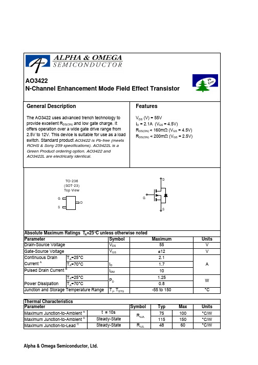
SymbolTyp Max 75100115150R θJL4860Maximum Junction-to-Lead CSteady-State°C/WParameterUnits Maximum Junction-to-Ambient A t ≤ 10s R θJA °C/W Maximum Junction-to-Ambient A Steady-State °C/W Thermal Characteristics AO3422AO3422Symbol Min TypMaxUnits BV DSS 55V 1T J =55°C5I GSS ±100nA V GS(th)0.6 1.32V I D(ON)10A 125160T J =125°C175210157200m Ωg FS 11S V SD 0.781V I S1A C iss 214300pF C oss 31pF C rss 12.6pF R g 1.33ΩQ g 2.6 3.3nC Q gs 0.6nC Q gd 0.8nC t D(on) 2.3ns t r 2.4ns t D(off)16.5ns t f 2ns t rr 2030ns Q rr 17nCTHIS PRODUCT HAS BEEN DESIGNED AND QUALIFIED FOR THE CONSUMER MARKET. APPLICATIONS OR USES AS CRITICAL COMPONENTS IN LIFE SUPPORT DEVICES OR SYSTEMS ARE NOT AUTHORIZED. AOS DOES NOT ASSUME ANY LIABILITY ARISING OUT OF SUCH APPLICATIONS OR USES OF ITS PRODUCTS. AOS RESERVES THE RIGHT TO IMPROVE PRODUCT DESIGN,FUNCTIONS AND RELIABILITY WITHOUT NOTICE.Body Diode Reverse Recovery Time Body Diode Reverse Recovery ChargeTurn-Off Fall Time SWITCHING PARAMETERS Total Gate Charge V GS =4.5V, V DS =27.5V, I D =2.1AGate Source Charge Gate Drain Charge Turn-On DelayTime V GS =10V, V DS =27.5V, R L =12Ω, R GEN =3ΩReverse Transfer Capacitance Turn-On Rise Time Turn-Off DelayTime Gate resistance V GS =0V, V DS =0V, f=1MHzForward Transconductance V DS =5V, I D =2.1A Diode Forward Voltage I S =1A Maximum Body-Diode Continuous CurrentDYNAMIC PARAMETERS Input Capacitance V GS =0V, V DS =25V, f=1MHz Output Capacitance R DS(ON)Static Drain-Source On-ResistanceV GS =4.5V, I D =2.1Am ΩV GS =2.5V, I D =1.5AGate Threshold Voltage V DS =V GS I D =250μA On state drain currentV GS =4.5V, V DS =5V V DS =44V, V GS =0VμA Gate-Source leakage current V DS =0V, V GS =±12V I F =2.1A, dI/dt=100A/μs I F =2.1A, dI/dt=100A/μsElectrical Characteristics (T J =25°C unless otherwise noted)Parameter Conditions STATIC PARAMETERS Drain-Source Breakdown Voltage I D =10mA, V GS =0V I DSS Zero Gate Voltage Drain Current A: The value of R θJA is measured with the device mounted on 1in 2FR-4 board with 2oz. Copper, in a still air environment with T A =25°C. The value in any given application depends on the user's specific board design. The current rating is based on the t ≤ 10s thermal resistance rating.B: Repetitive rating, pulse width limited by junction temperature.C. The R θJA is the sum of the thermal impedence from junction to lead R θJL and lead to ambient.D. The static characteristics in Figures 1 to 6 are obtained using 80 μs pulses, duty cycle 0.5% max.E. These tests are performed with the device mounted on 1 in 2FR-4 board with 2oz. Copper, in a still air environment with T A =25°C. The SOA curve provides a single pulse rating. Rev0: Oct 2005AO3422AO3422。
芯片手册

功能简述 ............................................................................ 46 编程指南 ............................................................................ 46 寄存器 .............................................................................. 47
pl3201芯片技术指标封装和管脚定义电器参数电特性测量项目符号测试条件测量点最小典型最大单位iwmax所有功能12ma工作电流iwmin所有功能禁用ma工作电压vw标准510pl3201单相多功能电子式载波电能表专用soc北京福星晓程电子科技股份有限公司芯片手册参考电压vref218参考电压温度系数30ppm相对agndupuni1pi1ni0pi0n600模拟输入vppsigin800mv时钟输入osc9620mhz有功功率误差1无功功率误差5vih24输入vil08vohioh3ma40输出voliol10ma04直流电源抑制输出频率误差250mv02交流电源抑制输出频率误差200mv100hz纹波03adc失调模拟输入直流失调13mv增益误差无失调极限参数项目符号极值单位储藏温度tstr60tsr150焊接温度焊接10tilt260ts215tif220工作温度topr40电源电压avdddvdd封装参数pl3201单相多功能电子式载波电能表专用soc北京福星晓程电子科技股份有限公司芯片手册pl3201单相多功能电子式载波电能表专用soc北京福星晓程电子科技股份有限公司芯片手册pl3201单相多功能电子式载波电能表专用soc北京福星晓程电子科技股份有限公司芯片手册pl3201单相多功能电子式载波电能表专用soc北京福星晓程电子科技股份有限公司芯片手册pl3201单相多功能电子式载波电能表专用soc北京福星晓程电子科技股份有限公司芯片手册管脚定义100pin80pin64pindescriptioni1p电流通道1模拟信号全差分输入端典型vpp450mv满量程pga4i2p电流通道2模拟信号全差分输入端典型vpp450mv满量程pga4un电压通道模拟信号全差分输入端典型vpp450mv满量程agndpwr芯片模拟部分电源地模拟部分地要与数字部分地分开qcf10无功瞬时功率脉冲输出校表用pcf11有功瞬时功率脉冲输出校表用s3012s3113lcdseg驱动引脚mclr141010全芯片手动复位输入上升沿下降沿均触发正常工作时要置1s01511s11612s21713lcdseg驱动引脚p2318p37191411p36201512p35211613p34221714端口端口复用说明
LINEAR LT3420 LT3420-1 数据手册

1LT3420/LT3420-123420faV CC Voltage..............................................................16V V BAT Voltage............................................................16V SW Voltage (Note 2)LT3420................................................................38V LT3420-1............................................................ 50V SEC Current......................................................±200mA R FB Current...........................................................±3mA R REF Voltage...........................................................2.5V CHARGE Voltage......................................................16V CT Voltage ..............................................................1.5V DONE Voltage..........................................................16V Current into DONE Pin..........................................±1mA Maximum Junction Temperature..........................125°C Operating Ambient Temperature Range(Note 3)..............................................–40°C to 85°C Storage Temperature Range.................–65°C to 150°C Lead Temperature (Soldering, 10 sec)..................300°CORDER PART NUMBER MS PART MARKINGT JMAX = 125°C, θJA = 100°C/W, θJC = 45°C/W(4-LAYER BOARD)LTYH LTAJGLT3420EMS LT3420EMS-1ABSOLUTE AXI U RATI GSW W WU PACKAGE/ORDER I FOR ATIOUUW (Note 1)ELECTRICAL CHARACTERISTICSThe q denotes the specifications which apply over the full operatingtemperature range, otherwise specifications are at T A = 25°C. V CC = V BAT = 3.3V, V CHARGE = V CC unless otherwise noted. (Note 3)PARAMETERCONDITIONSMIN TYP MAX UNITSMinimum Operating Voltage, V CC q2.2 2.5V Maximum Operating Voltage, V CC 16V V CC UVLO Hysteresis 40mV Minimum V BAT Voltage 1.6 1.8V Maximum V BAT Voltage 16V V BAT UVLO Hysteresis 275mV R REF Threshold Voltage0.98 1.00 1.02V q0.9751.025V R REF Pin Bias Current V RREF = 0V, Switching24µA V RFB = V BAT – 0.2V (Note 4)Quiescent CurrentV RREF = 1.1V, Not Switching 90130µA Quiescent Current in Shutdown V CHARGE = 0V, V IN = 3.3V 0.011µA Primary Side Current Limit LT3420 (Note 5) 1.20 1.4 1.60A LT3420-1 (Note 5)0.750.9 1.05A Secondary Side Current Limit LT3420 (Note 5)204050mA LT3420-1 (Note 5)51525mA Leakage Blanking Pulse Width LT3420200ns LT3420-10nsRefresh Timer Charge/Discharge Current V CT = 0.75V1.52.53.5µA Refresh Timer Upper Threshold 0.9 1.0 1.1V Refresh Timer Lower Threshold0.450.50.55VConsult LTC Marketing for parts specified with wider operating temperature ranges.12345R REF V BAT R FB V CC GND109876C TCHARGE DONE SEC SWTOP VIEWMS10 PACKAGE 10-LEAD PLASTIC MSOP345LT3420/LT3420-163420faU U UPI FU CTIO SR REF (Pin 1): Reference Resistor Pin. Place a resistor (R2)from the R REF pin to GND. 2k is recommended.V BAT (Pin 2): Battery Voltage Input. This pin should be connected to the power supply or battery, which supplies power to transformer T1. Must be locally bypassed.R FB (Pin 3): Feedback Resistor Pin. Place a resistor (R1)from the SW pin to the R FB pin. Set R1 according to the following formula:R R N RN V V SEC OUTD 121422=++[](.•)() (LT3420)R R NR N V V SEC OUT D 1222=++[]()() (LT3420-1)V OUT : Desired Output Voltage N: Transformer Turns RatioR SEC : Transformer Secondary Resistance V D : Diode Forward Voltage DropR2: Resistor from the R REF Pin to GND. 2k is a TypicalChoiceV CC (Pin 4): Input Supply Pin. Must be locally bypassed with a 4.7µF or larger ceramic capacitor.GND (Pin 5): Ground. Tie directly to local ground plane.SW (Pin 6): Switch Pin. This is the collector of the internal NPN power switch. Minimize the metal trace area con-nected to this pin to minimize EMI.SEC (Pin 7): Transformer Secondary Pin. Tie one end of the transformer secondary to this pin. Take care to use the correct phasing of the transformer (Refer to Figures 1and␣2).DONE (Pin 8): Done Output Pin. Open collector NPN output. DONE is pulled low whenever the chip is delivering power to the output and goes high when power delivery stops.CHARGE (Pin 9): Charge Pin. Drive CHARGE high (1.5V or more) to commence charging of the output capacitor.Drive to 0.2V or less to put the part in shutdown mode.C T (Pin 10): Refresh Timer Capacitor Pin. Place a capacitor from the C T pin to GND to set the refresh timer sample rate according to the following formula:C T = 2.5 • 10–6 • t REFRESHt REFRESH : Desired Refresh Period in Seconds.7SHUTDOWN CHARGING REFRESH1s/DIV3420 F05 Figure 5. Demonstrating 3 Operating Modes of LT3420: Shutdown, Charging and Refresh of Photoflash Capacitor8LT3420/LT3420-193420faof Q1 so that the peak current of Q1 is 1.4A and the mini-mum secondary current is 40mA (typical values).The previously described charging cycle must be halted when the output voltage reaches the desired value. The LT3420 monitors the output voltage via the flyback pulse on the SW pin. When Q1 turns off, the secondary side conducts current turning on diode D1. Since the diode is conducting and the SEC pin is at nearly ground, the voltage across the secondary is nearly equal to V OUT . The voltage across the primary is therefore close to V OUT /N. A current proportional to V OUT /N flows through R1 and into the R FB pin. The current flows out of the R REF pin through a resis-tor creating a ground referred voltage. When this voltage exceeds an internal 1V reference voltage, the output of comparator A3 goes high which resets the master latch. The Q output of the master latch goes low, disabling the entire power delivery block and enabling the refresh timer.Leakage Spike BlankingAnother function of the LT3420 is leakage spike blanking when the power switch, Q1, turns off. Right after Q1 turns off, a one-shot turns on Q2 for 200ns (typ). With Q2 on,comparator A3 is disabled. This function may prevent A3from false tripping on the leakage inductance spike on the SW pin. In practice, the PNP transistor Q3 filters out the leakage spike.Refresh TimerWhen the refresh timer is enabled, a 2.5µA current source is switched on, charging up the external timing capacitor,Figure 6b. Switching Waveforms with V OUT = 300V, V CC = V BAT = 3.3VFigure 6a. Switching Waveforms with V OUT = 100V, V CC = V BAT = 3.3V OPERATIOUC3, from its initial voltage towards 1V. When the voltage on C3 reaches 1V, the polarity of the current source changes and 2.5µA discharges C3. When the voltage on C3 reaches 0.5V, the refresh timer sends a set pulse to the master latch,which puts the LT3420 into the charging mode.Interface/ControlThe CHARGE pin serves two functions. The first is to enable or shutdown the part depending on the level of the pin (high = enable, low = s hutdown). The second is to force the part into the charging mode (low →high transi-tion). The LT3420 also has a DONE pin, which signals whether or not the part is done charging the photoflash capacitor. The DONE pin is an open collector NPN switch (Q5) so an external pull-up resistor is needed. Whenever the part is in charging mode, DONE will be low. DONE will go high when the charging mode is complete. Both the CHARGE and DONE pins can be easily interfaced to a microprocessor in a digital or film camera.LT3420-1 DifferencesThe LT3420-1 has different primary and secondary cur-rent limit levels. The primary current limit level of the LT3420-1 is 1A (typ) and the secondary current limit is 15mA (typ). The LT3420-1 has no leakage spike blanking which causes no problems since the PNP transistor, Q3,provides adequate filtering. Finally, the breakdown voltage of the SW pin of the LT3420-1 is higher at 50V.I SW 1A/DIVV SW 20V/DIVI SEC200mA/DIV 2µs/DIV3420 F06a2µs/DIV3420 F06bI SW 1A/DIVV SW 20V/DIVI SEC200mA/DIVLT3420/LT3420-1103420faCOMPONENT SELECTION Choosing the Right TransformerThe flyback transformer plays a key role in any LT3420/LT3420-1 application. A poorly designed transformer can result in inefficient operation. Linear Technology Corpora-tion has worked with a number of transformer manufactur-ers to develop specific transformers for use with the LT3420/LT3420-1. These predesigned transformers are sufficient for a large majority of the applications that may be encountered. In some cases, the reader may choose to design his own transformer or may simply be curious about the issues involved in designing the transformer. The fol-lowing is a brief discussion of the issues relating to trans-former design.Transformer Turns RatioThe turns ratio for the transformer, N, should be high enough so that the absolute maximum voltage rating for the NPN power switch is not exceeded. When the power switch turns off, the voltage on the collector of the switch (SW Pin) will “fly” up to the output voltage divided by N plus the battery voltage (neglecting the voltage drop across the rectifying diodes). This voltage should not exceed the 38V (LT3420) or 50V (LT3420-1) breakdown rating of the power switch.Choose the minimum N by the following formula.N V V LT N V V LT MIN OUTBAT MIN OUTBAT ≥≥−3834205034201–()–()For an LT3420 design, a 5V battery voltage and a 330V output results in a N MIN of 10 so a turns ratio of 10 or greater should be used.Transformer Primary InductanceA flyback transformer needs to store substantial amounts of energy in the core during each switching cycle. The transformer, therefore, will generally require an air gap.The use of an air gap in the core makes the energy storage ability, or inductance, much more stable with temperature and variations in the core material. Most core manufactur-ers will supply standard sizes of air gaps with a given type of core, resulting in different A L values. A L is the induc-tance of a particular core per square turns of winding. To get a certain inductance, simply divide the desired induc-tance by the A L value and take the square root of the result to find the number of turns needed on the primary of the transformer.The LT3420/LT3420-1 detect the output voltage via the flyback pulse on the SW pin. Since this can only occur while the power switch is off, an important criteria is that the value of the primary inductance of the transformer be larger than a certain minimum value. The switch off time should be 500ns or larger for the LT3420 and 350ns or larger for the LT3420-1. The minimum inductance can be calculated with the following formula:L V N N LT L V N N LT PRI OUTPRI OUT≥≥−50010140043420350101000153420199•••(.–.)()•••(.–.)()––V OUT : Target Output Voltage N: Transformer Turns Ratio Transformer Leakage InductanceThe leakage inductance of the transformer must be care-fully minimized for both proper and efficient operation of the part. The DC voltage rating of the SW pin on the LT3420is 38V while on the LT3420-1 it is 50V. These ratings are for DC blocking voltages only and additional precautionsAPPLICATIO S I FOR ATIOW UUU11123420faAPPLICATIO S I FOR ATIOW UUU efficiency of the circuit. In addition, the effective capaci-tance on the primary is largely dominated by the actual secondary capacitance. This is simply a result of any secondary capacitance being multiplied by N 2 when re-flected to the primary. Since N is generally 10 or higher, a small capacitance of 10pF on the secondary is 100 times larger, or 1.0nF, on the primary. This capacitance forms a resonant circuit with the primary leakage inductance of the transformer. As such, both the primary leakage induc-tance and secondary side capacitance should be mini-mized.Table 2 shows various predesigned transformers along with relevant parameters. Contact the individual trans-former manufacturer for additional information or customization.Table 2a. Predesigned Transformers, LT3420TURNS L SIZEPARTRATIO (µH)LxWxH (mm)VENDOR SRW10EPC 1:122410.9x10.8x5.2TDK-U01H003(847) 803-61006375-T1081:121510.8x9.5x3.6Sumida(847) PA03671:12249.1x9.1x5.1Pulse(858) SBL-6.41:1217.510.3x6.4x5.2Kijima Musen852-2489-8266***********************Table 2b. Predesigned Transformers, LT3420-1TURNS L SIZEPARTRATIO (µH)LxWxH (mm)VENDOR SBL-5.6S-21:10155.6x8.5x3.0Kijima Musen852-2489-8266***********************LDT565630T 1:10.214.5 5.8x5.8x3.0TDK-002(847) 803-6100DIODE SELECTIONThe rectifying diode(s) should be low capacitance type with sufficient reverse voltage and forward current rat-ings. The peak reverse voltage that the diode(s) will see is approximately:V PK-R ≈+()V N V OUT BAT (•)•.165The peak current of the diode is simply:I I PK-SEC PK-SEC ==−1434201034201.().()AN LT AN LT For the circuit of Figure 1 with V BAT of 3.3V, V PK-R is 590V and I PK-SEC is 116mA. Table 3 shows various diodes that can work with the LT3420/LT3420-1. These are chosen for low capacitance and high reverse blocking voltage. Use the appropriate number of diodes to achieve the necessary reverse breakdown voltage.Table 3MAX REVERSE CAPACITANCE PARTVOLTAGE (V)(pF)VENDOR GSD2004S 2x3005Vishay(Dual diode)(402) BAS21250 1.5Philips Semiconductor (Single diode)(800) 234-7381ISS3062x2503Toshiba (Dual Diode)(949) 455-2000www.semicon.toshiba.co.jp133420faCAPACITOR SELECTIONThe V BAT and V CC decoupling capacitors should be multi-layer ceramic type with X5R or X7R dielectric. This insures adequate decoupling across wide ambient temperature ranges. A good quality ceramic capacitor is also recom-mended for the timing capacitor on the C T pin. Avoid Y5V or Z5U dielectrics.Selectively Disabling the LT3420/LT3420-1The LT3420/LT3420-1 can be disabled at any time, even during the charge phase. This may be useful when a digital camera enters a sensitive data acquisition phase. Figure 8illustrates this feature. Midway through the charge cycle,the CHARGE pin is brought low, which disables the part.After the sensitive data operation is complete, the CHARGE pin is brought high and the charging operation continues.Measuring EfficiencyMeasuring the efficiency of a circuit designed to charge large capacitive loads is a difficult issue, particularly with photoflash capacitors. The ideal way to measure the efficiency of a capacitor charging circuit would be to find the energy delivered to the output capacitor (0.5 • C • V 2)and divide it by the total input energy. This method does not work well here because photoflash capacitors are far from ideal. Among other things, they have relatively high leakage currents, large amounts of dielectric absorption,and significant voltage coefficients. A much more accu-rate, and easier, method is to measure the efficiency as a function of the output voltage. In place of the photoflash capacitor, use a smaller, high quality capacitor, reducing errors associated with the non-ideal photoflash ing an adjustable load, the output voltage can be set anywhere between ground and the maximum output voltage. The efficiency is measured as the output power (V OUT • I OUT ) divided by the input power (V IN • I IN ). This method also provides a good means to compare various charging circuits since it removes the variability of the photoflash capacitor from the measurement. The total efficiency of the circuit, charging an ideal capacitor, would be the time average of the given efficiency curve, over time as V OUT changes.Adjustable Input CurrentWith many types of modern batteries, the maximum allowable current that can be drawn from the battery is limited. This is generally accomplished by active circuitry or a polyfuse. Different parts of a digital camera may require high currents during certain phases of operation and very little at other times. A photoflash charging circuit should be able to adapt to these varying currents by drawing more current when the rest of the camera is drawing less, and vice-versa. This helps to reduce the charge time of the photoflash capacitor, while avoiding theAPPLICATIO S I FOR ATIOW UUU Figure 8. Halting the Charge Cycle at Any TimeV OUT 50V/DIVCHARGENO CHARGE0.5s/DIV3420 F085V/DIVV CHARGE1415160.5s/DIV3420 TA02cV BAT = 3.3V171819Information furnished by Linear Technology Corporation is believed to be accurate and reliable.However, no responsibility is assumed for its use. Linear Technology Corporation makes no represen-tation that the interconnection of its circuits as described herein will not infringe on existing patent rights.20Linear Technology Corporation1630 McCarthy Blvd., Milpitas, CA 95035-7417(408) 432-1900 q FAX: (408) 434-0507 q © LINEAR TECHNOLOGY CORPORA TION 2002LT/TP 0903 1K • PRINTED IN USA。
反激式开关电源电子数据表格
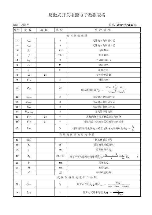
次级绕组匝数
NS
=
NP n
NS
=
NP
·UO+UF UOR
1
反馈级绕组匝数 NF = NS·UUFOB++UUFF12
真空中的磁导率
磁芯不留间隙时的相对磁导率μr =
AL·l µo·SJ
磁芯气隙宽度δ=
µo·SJ
Hale Waihona Puke LPP2-1 ALδ= µo NP2SJ - l
LP
µr
磁芯留间隙时的电感系数 ALG=
反激式开关电源电子数据表格
编制:周国平
日期:2005-4-5-11:19:45
序号 参 数
数 据
单 位
.
输入参数变量
参 数 说 明
1
umin
V
2
umax
V
3
fL
Hz
4
f
kHz
交流输入电压最小值 交流输入电压最大值
电网频率 开关频率
5
UO
V
6
PO
W
7
η %
反激式开关电源电子数据表格
编制:周国平 序号 参 数
27
IP
28
IR
29
IRMS
30
Lmin
31
LP
32
n
33
NP
34
NS
35
NF
36
µo
37
µr
38
δ
39
ALG
40
BM
41
DPM
42
Dpm
43 公制线径
44
SP
45
J
数 据
PL34120191000DFEX资料
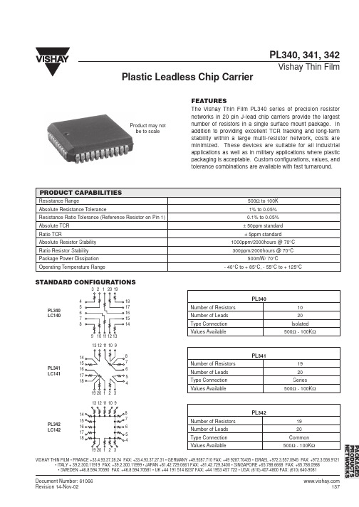
Product may not be to scale
PRODUCT CAPABILITIES
Resistance Range Absolute Resistance Tolerance Resistance Ratio Tolerance (Reference Resistor on Pin 1) Absolute TCR Ratio TCR Absolute Resistor Stability Ratio Resistor Stability Package Power Dissipation Operating Temperature Range 500Ω to 100K 1% to 0.05% 0.1% to 0.05% ± 50ppm standard ± 5ppm standard 1000ppm/2000hours @ 70°C 300ppm/2000hours @ 70°C 500mW/ 70°C - 40°C to + 85°C, - 55°C to + 125°C
STANDARD CONFIGURATIONS
3 2 1 20 19 4 5 6 7 8 9 10 11 12 13 18 17 16 15 14
PL340 Number of Resistors Number of Leads Type Connection Values Available 10 20 Isolated 500Ω - 100KΩ
0.050 inches 4° typical 0.5° typical B1 FP G 4° typical J A, B 0.120” DIAMETER 0.003 - 0.004” DEPTH A1 0.027 inches
Plastic Leadless Chip Carrier
DW01中文资料
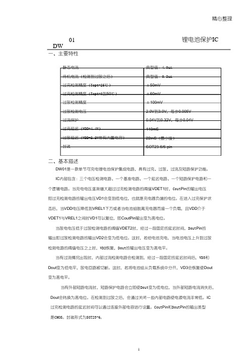
精心整理DW01锂电池保护IC一、主要特性静态电流待机电流(检测到过放之后)过充检测精度(Topt=25℃)过充检测精度(Topt=0到50℃)过放检测精度过放检测电压过流保护过充延迟(VDD=4.4V)过放延迟(VDD=2.2V带有内置电容)封装典型值:4.0uA典型值:0.2uA±50mV±60mV±100mV2.0V到3.0V,每步0.005V 0.04V到0.32V,每步0.04V 110mS22mS(最小值)SOT23-6/6-pin二、基本描述DW01是一款单节可充电锂电池保护集成电路,具有过充、过放、过流及短路保护功能。
IC内部包含:三个电压检测电路、一个基准电路、一个延迟电路、一个短路保护电路和一个逻辑电路。
当充电电压逐渐增大超过过充检测电路的阈值VDET1时,Cout Pin的输出电压即过充检测电路的输出电压VD1会变到低电位,也就是充电器负端的电位。
在进入过充保护状态后,当VDD电压降低到VREL1下方或者当电池组脱离充电器而接一个负载,且VDD介于VDET1与VREL1之间时VD1可以复位,即CoutPin输出变为高电位。
当放电电压低于过放检测电路的阈值VDET2时,经过一段固定的延迟时间,Dout Pin的输出即过放检测电路的输出VD2会变为低电位。
这时,若给电池充电,当电池电压上升到过放检测电路的阈值电压之上时,VD2恢复,Dout的输出电压变为高电平。
当有过流情况出现时,内部过流检测电路会检测到,经过一段固定的延迟时间后,VD3和Dout变为低电平,放电回路被切断。
这时,若将电池组从负载系统中分开,VD3会恢复使Dout 变为高电平。
当有外部短路电流时,短路保护电路会立即使Dout变为低电位,当外部短路电流消失后,Dout会转换为高电位。
在检测到过放之后,会通过关闭一些内部电路使电源电流非常低。
IC过充检测电路的延迟时间可以通过连接外部电容进行设置。
迈普路由器基本配置与维护

允许本端
172.168.0.0/24这个网段的地址到任意地址
? interface gigaethernet0
进入相应端口
? ip address 116.52.163.178 255.255.255.248 配置IP地址
? ip nat outside
应用NAT为出方向
? exit
? interface gigaethernet2
以太口保活报文配置
设置以太网接口向特定的地址发送保活报文。接口向配置的 gateway 地址定期发送 arp 请求报文。 当接口连续 3次收不到 arp 响应报文时,第 4次arp 请求报文超时后接口 down ,直到再次收到 arp 响应报文时,接口 up 。
命令 router(config-if-fastethernet0)#keepalive gateway A.B.C.D <0_32767>
为100M或10M
? ?LINK/ACT 以太网口连接指示灯,以太口建链灯恒亮,有数据收发灯闪烁
路由器的配置模式
1. 通过console接口,采用shell命令进行配 置;
2. 通过Telnet远程登录到路由器上配置; 3. 通过SSH远程登录到路由器上配置。 4. 通过SNMP网管系统对路由器进行配置。
ACL配置
?路由器中ACL的分类
–标准访问列表
?使用1~1000内的任一编号标识 ?仅通过源地址参数访问控制
–扩展访问列表
?使用1001~2000内的任一编号标识 ?通过源、目的地址,协议、端口等多种参数的组合进行访问控制
?ACL的配置任务
–创建标准访问列表 或创建扩展访问列表) –应用到相应端口的出或入方向 注:没有应用到接口的ACL是不生效的
带传动知识大全
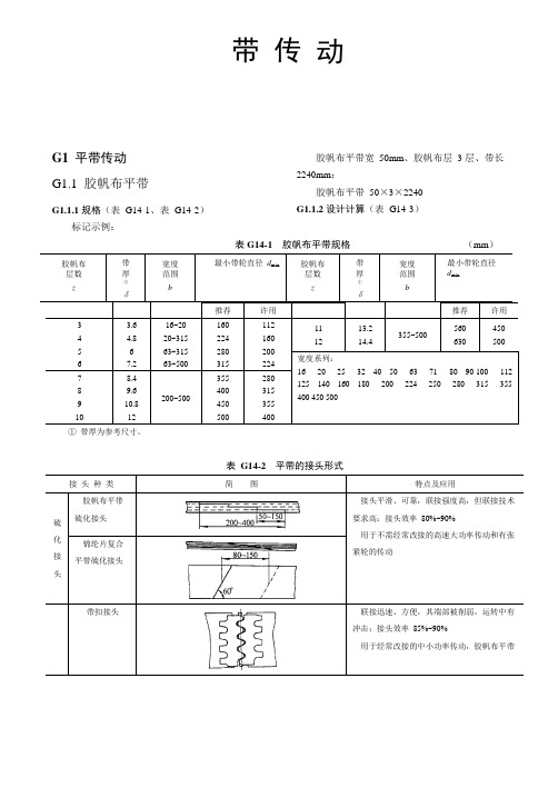
带 传 动G1 平带传动 G1.1 胶帆布平带G1.1.1 规格(表 G14-1、表 G14-2)标记示例:胶帆布平带宽 50mm 、胶帆布层 3 层、带长 2240mm :胶帆布平带 50×3×2240 G1.1.2 设计计算(表 G14-3)表 G14-1 胶帆布平带规格(mm )① 带厚为参考尺寸。
表 G14-2 平带的接头形式183(续)表G14-3 胶帆布平带传动的设计计算d1=(1100~1350)或d1= 6000vπn1πd n184(续)表G14-4 胶帆布平带单位截面积传递的基本额定功率P0(α=180°、载荷平稳、预紧应力σ0= 1.8MPa) (kW/cm2)注:本表只适用于b<300mm 的胶帆布平带。
185表 G14-5 平带传动的包角修正系数 K α表 G14-6 传动布置系数 K βG1.2 锦纶片复合平带G1.2.1 规 格锦纶片复合平带按承载层——锦纶片的传动能力分为轻型 L 、中型 M 、重型 H 和特轻型 EL 、加重型 EH 等几种,其尺寸规格见表 G14-7。
表 G14-7 锦纶片复合平带规格 (mm )注:1. LL ——两面贴铬鞣革;2. LR ——一面贴铬鞣革,一面贴橡胶布层; (续)LT ——一面贴铬鞣革,一面贴特殊织物层; 3. RR ——两面均贴橡胶布层;4. 宽度系列与胶帆布平带相同,参见表 G14-1。
G1.2.2 设计计算锦纶片复合平带的设计计算可参照表 G14-3 进行。
但计算时应考虑下列几点:1) 选择带型时,先根据载荷的大小和变化情况选择类型,对于中载、重载和载荷变化大的传动,宜选用 LL 或 LR 、LT 型。
然后根据设计功率 P d 和小带轮转速 n 1 参考图 G14-1 选择带型。
2) 小带轮直径 d 1 允许比表 G14-3 的计算值小 30%~35%,但必须大于表 G14-7 规定的 d min ,并应使186带速v>10~15m/s。
- 1、下载文档前请自行甄别文档内容的完整性,平台不提供额外的编辑、内容补充、找答案等附加服务。
- 2、"仅部分预览"的文档,不可在线预览部分如存在完整性等问题,可反馈申请退款(可完整预览的文档不适用该条件!)。
- 3、如文档侵犯您的权益,请联系客服反馈,我们会尽快为您处理(人工客服工作时间:9:00-18:30)。
PACKAGED PRODUCTS NETWORKS
VISHAY THIN FILM • FRANCE +33.4.93.37.28.24 FAX: +33.4.93.37.27.31 • GERMANY +49.9287.710 FAX: +49 9287.70435 • ISRAEL +972.3.557.0945 FAX: +972.3.558.9121 • ITALY + 39.2.300.11919 FAX: +39.2.300.11999 • JAPAN +81.42.729.0661 FAX: +81.42.729.3400 • SINGAPORE +65.788.6668 FAX: +65.788.0988 • SWEDEN +46.8.594.70590 FAX: +46.8.594.70581 • UK +44 191 514 8237 FAX: +44 1953 457 722 • USA: (610) 407-4800 FAX: (610) 640-9081
元器件交易网
PL340, 341, 342
Vishay Thin Film
Plastic Leadless Chip Carrier
FEATURES
The Vishay Thin Film PL340 series of precision resistor networks in 20 pin J-lead chip carriers provide the largest number of resistors in a single surface mount package. In addition to providing excellent TCR tracking and long-term stability within a large multi-resistor network, costs are minimized. These devices are suitable for all industrial applications as well as in military applications where plastic packaging is acceptable. Custom configurations, values, and tolerance combinations are available with fast turnaround.
C1
20 LEAD PACKAGE DIMENSIONS in inches [millimeters]
A MINIMUM 0.385 [9.78] NOMINAL 0.390 [9.91] MAXIMUM 0.395 [10.03] A1 0.348 [8.84] 0.350 [8.89] 0.352 [8.94] B 0.385 [9.78] 0.390 [9.91] 0.395 [10.03] B1 0.348 [8.84] 0.350 [8.89] 0.352 [8.94] C --0.045 [1.14] --C1 --0.045 [1.14] --D --0.015 [0.38] --D1 --0.015 [0.38] --E ------F --0.178 [4.52] --G --0.108 [2.74] --I 0.026 0.66 ----J --P ---
STANDARD CONFIGURATIONS
3 2 1 20 19 4 5 6 7 8 9 10 11 12 13 18 17 16 15 14
PL340 Number of Resistors Number of Leads Type Connection Values Available 10 20 Isolated 500Ω - 100KΩ
PL341 LC141
PL342 Number of Resistors Number of Leads Type Connection Values Available 19 20 Common 500Ω - 100KΩ
PL342 LC142
PACKAGED PRODUCTS NETWORKS
VISHAY THIN FILM • FRANCE +33.4.93.37.28.24 FAX: +33.4.93.37.27.31 • GERMANY +49.9287.710 FAX: +49 9287.70435 • ISRAEL +972.3.557.0945 FAX: +972.3.558.9121 • ITALY + 39.2.300.11919 FAX: +39.2.300.11999 • JAPAN +81.42.729.0661 FAX: +81.42.729.3400 • SINGAPORE +65.788.6668 FAX: +65.788.0988 • SWEDEN +46.8.594.70590 FAX: +46.8.594.70581 • UK +44 191 514 8237 FAX: +44 1953 457 722 • USA: (610) 407-4800 FAX: (610) 640-9081
0.050 inches 4° typical 0.5° typical B1 FP G 4° typical J A, B 0.120” DIAMETER 0.003 - 0.004” DEPTH A1 0.027 inches
Plastic Leadless Chip Carrier
C
D PIN 1 LOCATOR D1
0.320 0.150 [8.13] [3.81] -----
ORDERING INFORMATION
Example: PL340-20-10-1000-F-F-B-C, 20 Lead PLCC, 1000Ω Isolated Resistors, Absolute Tolerance: 1.0%, Ratio Tolerance: 0.1%, Absolute TCR: 25ppm/°C, Ratio TCR: 2ppm/°C. PL340 20 10 1000 F F B C MODEL NUMBER OF NUMBER OF RESISTANCE ABSOLUTE RATIO ABSOLUTE TCR RATIO TCR LEADS RESISTORS VALUE TOLERANCE TOLERANCE PPM/°C PPM/°C % % (To RREF) The first 3 digits are significant PL341 B = 0.1* D = 0.050* B = 25 C = 2* figures and the last specifies the PL342 C = 0.2* F = 0.100 D = 50 D = 3* number of zeros to follow. D = 0.5 H = 0.250 E = 100 F = 5* “R” designates the decimal F = 1.0 J = 0.500 G = 10 point. G = 2.0 K = 1.000 X = N/A Example: 100 ohms = 1000 J = 5.0 X = N/A 1000 ohms = 1001 K = 10.0 M = 20.0 *Value dependent NOTE: Factory will covert order number into final part number.
PL340 LC140
13 12 11 10 9 14 15 16 17 18 19 20 1 2 3
13 12 11 10 9 14 15 16 17 18 19 20 1 2 3 8 7 6 5 4
8 7 6 5 4
PL341 Number of Resistors Number of Leads Type Connection Values Available 19 20 Series 500Ω - 100KΩ
Document Number: 61066 Revision 14-Nov-02
137
元器件交易网
PL340, 341, 342
Vishay Thin Film
PACKAGE OUTLINE DRAWING PLASTIC LEADLESS CHduct may not be to scale
PRODUCT CAPABILITIES
Resistance Range Absolute Resistance Tolerance Resistance Ratio Tolerance (Reference Resistor on Pin 1) Absolute TCR Ratio TCR Absolute Resistor Stability Ratio Resistor Stability Package Power Dissipation Operating Temperature Range 500Ω to 100K 1% to 0.05% 0.1% to 0.05% ± 50ppm standard ± 5ppm standard 1000ppm/2000hours @ 70°C 300ppm/2000hours @ 70°C 500mW/ 70°C - 40°C to + 85°C, - 55°C to + 125°C
138
Document Number: 61066 Revision 14-Nov-02
