arduino UNO bootloader 固件写入
Arduino使用教程和典型范例
扩展 I/O
gh 与 toHigh 之间。
• pow(base, exponent) 开方函数,base 的 exponent 次方。 • sq(x) 平方 • sqrt(x) 开根号
三角函数
• sin(rad) • cos(rad) • tan(rad)
随机数函数
• randomSeed(seed) 随机数端口定义函数,seed 表示读模拟口 analogRead(pin)函数 。 • long random(max) 随机数函数,返回数据大于等于 0,小于 max。 • long random(min, max) 随机数函数,返回数据大于等于 min,小于 max。
Arduino 使用教程
梦厂
北京龙凡汇众机器人科技有限公司 E_mail: service@
Arduino 使用教程
http://
第一课 Arduino 语言
DreamFactory
2
Arduino 语言是建立在 C/C++基础上的,其实也就是基础的 C 语言,Arduino 语言只不过把 AVR 单片机(微控制 器)相关的一些寄存器参数设置等都函数化了,不用我们去了解他的底层,让不太了解 AVR 单片机(微控制器)的 朋友也能轻松上手。
arduinoccenreferencelibrarieseepromeeprom读写程序库ethernet以太网控制器程序库liquidcrystallcd控制程序库servo舵机控制程序库softwareserial任何数字io口模拟?口程序库stepper步进电机控制程序库wiretwii2c总线程序库matrixled矩阵控制程序库spriteled矩阵图象处?控制程序库第二课arduino的数字模拟端口arduino控制器内带bootloader程序是系统上电后运?的第一段代码就好比pc机bios中的程序启动就进?自检配置端口等等当然单片机就是靠烧写熔丝位来设定上电从boot区启动的使用这个程序就可以直接把从?口发来的程序存放到flash区中
基于USBASP烧写Arduino bootloader和application固件
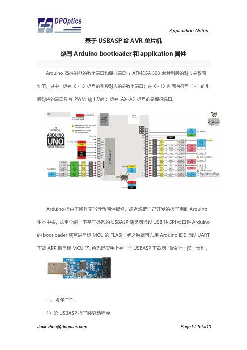
基于USBASP给AVR单片机烧写Arduino bootloader和application固件 Arduino 微控制器的数字端口和模拟端口与 ATMEGA 328 芯片引脚的对应关系图如下。
其中,标有 0~13 标号的引脚对应的是数字端口;在 0~13 前面有符号“~”的引脚对应的端口具有 PWM 输出功能;标有 A0~A5 标号的是模拟端口。
Arduino板由于操作不当导致固件损坏,或者想把自己开发的板子用到Arduino 生态中去,这里介绍一下基于外购的USBASP烧录器通过USB转SPI接口将Arduino 的bootloader烧写进目标MCU的FLASH,就之后就可以用Arduino IDE通过UART 下载APP到目标MCU了。
首先确保手上有一个USBASP下载器,淘宝上一搜一大堆。
一、准备工作:1)给USBASP板子装驱动程序注意选择好驱动程序所在名所以拒绝安装驱动程序,此名信息》一文,设置window 然后再尝试安装驱动程序。
电子”淘宝店买的下载板,但实太老了,结果智峰固件下载下载板到目标板连线错误,USBasp-win-driver-x86-文件到目标MCU。
下图是2)连接USBASP 到Ard注意USBASP 下载接口是插针,需要按下图的管脚定义序所在目录之后,win10可能会弹窗报错,说INF 序,此刻请参考《解决Win10安装驱动时,INF ndows 系统有条件重启,需选择“禁用驱动程序强序。
注意USBasp 的驱动程序也讲究版本,我图便宜板,但店家提供的驱动程序libusb0.dll 的版本是下载软件PROGISP V1.72运行时会报错说没有找误,我只得将驱动程序换成其他店家提供的V1.2.4-x64-ia64-v1.2.4,这之后才能成功下载bootlo 图是安装好驱动程序之后的“设备管理器”截屏:Arduino UNO 接口是10PIN 插针,而Arduino UNO 板载的下载脚定义用杜邦线飞线连接。
ardunin_uno_实验指导手册_概述说明

ardunin uno 实验指导手册概述说明1. 引言1.1 概述本实验指导手册旨在为初学者提供关于Ardunio Uno的详细介绍和操作指南。
Ardunio Uno是一种开放源代码的单片机开发板,广泛应用于电子原型设计和教育领域。
通过本手册,读者将了解Ardunio Uno的硬件组成、软件平台以及如何进行基本实验。
1.2 文章结构本手册分为五个主要部分:引言、Ardunio Uno实验介绍、实验准备与环境搭建、Ardunio Uno实验步骤与指导,以及实验结果分析与总结。
每个部分都包含多个子节,便于读者按照顺序查阅或跳转到感兴趣的内容。
1.3 目的本手册的目标是帮助读者快速上手并掌握使用Ardunio Uno进行电子原型设计的基础知识与技能。
通过学习本手册中提供的实验步骤与指导,读者能够理解Ardunio Uno的工作原理,并能够独立完成简单的电路搭建和程序编写。
同时,通过对实验结果进行分析和总结,读者将能够更好地理解和掌握Ardunio Uno实验中的常见问题及解决方法,以及对未来实验的思考和展望。
以上为文章“1. 引言”部分的内容。
2. Ardunio Uno实验介绍2.1 Ardunio Uno概述Arduino Uno是由意大利的开发商设计并推出的一款基于ATmega328P单片机的微控制板。
它具有易于使用、灵活性高和成本低廉等特点,广泛应用于电子原型设计、物联网项目以及学术研究等领域。
Arduino Uno采用了开源硬件和软件平台,用户可以充分发挥想象力和创造力,通过编写简单的代码与各种传感器、执行器等交互。
2.2 Ardunio Uno硬件组成Arduino Uno主板采用ATmega328P单片机作为核心处理器,并配备了数字输入/输出引脚(Digital I/O)、模拟输入引脚(Analog Input)、PWM输出引脚、串口通信接口、USB接口、电源接口等。
其中数字输入/输出引脚可用于连接外部设备如按钮、LED灯等;模拟输入引脚则可接收模拟传感器数据;PWM输出引脚可实现对LED灯的亮度调节;而串口通信接口和USB接口则为与计算机或其他设备进行数据传输提供了便利。
arduino bootloader原理
arduino bootloader原理
Arduino bootloader即为Arduino引导程序,其原理是将Arduino程序实现在ATmega328P芯片的flash存储器中,以便后续通过串口通信和计算机连接进行编程和程序更新。
在引导程序中,Arduino通过串口通信接收来自计算机的指令进行程序烧录和数据传输,同时也能够使程序从之前烧入的flash存储器中自动启动运行。
这样做的好处是可以
避免使用专业的编程器进行单片机编程,只要使用USB与计算机连接,就可以随时更新程序,在使用过程中更加方便、灵活。
Arduino引导程序可以分为两部分,第一部分为"bootloader",即引导区,它占用了ATmega328P的0号bootloader区,该存储区大小为512个字节,用于存储引导程序的一些指令。
第二部分是用户程序区,即Sketch区,用于存储用户编程的程序以及数据,它的大小为ATmega328P的flash总大小的95%左右,其余留作操作系统区和引导区等。
使用引导程序烧写的程序有一定的局限性,由于引导程序本身也需要占用一部分
Flash空间,因此用户程序的可用空间也会受到影响,而且程序运行的速度也会略微变慢。
但是这些影响并不会对Arduino的应用场景造成影响,因为Arduino针对的是一些中小型
的物联网应用,实现简单控制逻辑即可,而且其研发周期短、应用面广,成本低廉等优点,使得该产品被广泛应用于可穿戴设备、智能家居、自动巡航等领域。
总之,Arduino bootloader可以使产品研发更快、更便捷,使代码开发和调试更加方便,甚至使得一些非专业开发人员也可以快速入门和实现想法,这种开发方式为物联网的
发展做出了不小的贡献。
Arduino认知

Arduino认知这学期我们接触了一个新的课程——Arduino。
看着很难懂的一个名称,其实内容很有趣,过程很精彩,并且与上学期学的C语言有一定的相通之处,这给我们的学习过程减轻了很多难处。
这个学科我们一共做了11个实验,分别是光敏电阻、PWN脉宽调制、火焰传感器、4*4数码矩阵、温度传感器、4位数码管显示、人体传感器、RGB三色基LED、舵机控制、LCD1602、超声波测距。
每一个实验都都有不同的实验结果,会给我们带来不一样的体验,给我们增加了很多新奇的体验。
比如说,光敏电阻会因为光感的强弱来改变电阻的闪动频率;温度传感器可以检测到温度,改变呈现给我们数值;4位数码管显示器也很有意思,在程序上输入你想在数码管上显示的字母、数字,待程序完成并执行后就可以在数码管的液晶屏上看到你想呈现的东西;舵机控制的实验,可以看到舵机的螺旋桨转动;RGB三色基LED会出现红绿蓝三色接替闪烁,等等。
每完成一个实验,看到相应的实验结果就满满的成就感。
这里面的实验每一个都需要对应的程序来实现,所以我们每做一个实验的第一步就是敲程序,程序或多或少会有些枯燥,但一想到可以看不同的实验现象就会活力满满。
接下来就具体介绍以下Arduino的来源、作用及实用工具等。
Arduino是源于意大利的一套开源硬件开发平台,他的的作用是能通过各种各样的传感器来感知环境,通过控制灯光、马达和其他的装置来反馈、影响环境。
板子上的微控制器可以通过Arduino的编程语言来编写程序,编译成二进制文件,烧录进微控制器。
特色:可开放源代码的电路图设计,程序开发接口免费下载,也可依个人需求自己修改。
是使用低价格的微处理控制器(AVR系列控制器),可以采用USB接口供电,不需外接电源,也可以使用外部9VDC输入。
Arduino支持ISP在线烧,可以将新的“bootloader”固件烧入AVR芯片。
有了bootloader之后,可以通过串口或者USB to RS232线更新固件。
Arduino UNO R3 产品参考指南说明书

Product Reference ManualSKU: A000066DescriptionThe Arduino UNO R3 is the perfect board to get familiar with electronics and coding. This versatile microcontroller is equipped with the well-known ATmega328P and the ATMega 16U2 Processor.This board will give you a great first experience within the world of Arduino.Target areas:Maker, introduction, industriesFeaturesATMega328P ProcessorMemoryAVR CPU at up to 16 MHz32KB Flash2KB SRAM1KB EEPROMSecurityPower On Reset (POR)Brown Out Detection (BOD)Peripherals2x 8-bit Timer/Counter with a dedicated period register and compare channels1x 16-bit Timer/Counter with a dedicated period register, input capture and compare channels1x USART with fractional baud rate generator and start-of-frame detection1x controller/peripheral Serial Peripheral Interface (SPI)1x Dual mode controller/peripheral I2C1x Analog Comparator (AC) with a scalable reference inputWatchdog Timer with separate on-chip oscillatorSix PWM channelsInterrupt and wake-up on pin changeATMega16U2 Processor8-bit AVR® RISC-based microcontrollerMemory16 KB ISP Flash512B EEPROM512B SRAMdebugWIRE interface for on-chip debugging and programmingPower2.7-5.5 volts444445556677777789910101111111212131313CONTENTS1 The Board1.1 Application Examples 1.2 Related Products 2 Ratings2.1 Recommended Operating Conditions 2.2 Power Consumption 3 Functional Overview3.1 Board Topology 3.2 Processor 3.3 Power Tree 4 Board Operation4.1 Getting Started - IDE4.2 Getting Started - Arduino Web Editor 4.3 Getting Started - Arduino IoT Cloud 4.4 Sample Sketches 4.5 Online Resources 5 Connector Pinouts5.1 JANALOG 5.2 JDIGITAL5.3 Mechanical Information5.4 Board Outline & Mounting Holes 6 Certifications6.1 Declaration of Conformity CE DoC (EU)6.2 Declaration of Conformity to EU RoHS & REACH 211 01/19/20216.3 Conflict Minerals Declaration 7 FCC Caution8 Company Information 9 Reference Documentation 10 Revision History1 The Board1.1 Application ExamplesThe UNO board is the flagship product of Arduino. Regardless if you are new to the world of electronics or will use the UNO as a tool for education purposes or industry-related tasks.First entry to electronics: If this is your first project within coding and electronics, get started with our most used and documented board; Arduino UNO. It is equipped with the well-known ATmega328P processor, 14 digital input/output pins, 6 analog inputs, USB connections, ICSP header and reset button. This board includes everything you will need for a great first experience with Arduino.Industry-standard development board: Using the Arduino UNO board in industries, there are a range of companies using the UNO board as the brain for their PLC’s.Education purposes: Although the UNO board has been with us for about ten years, it is still widely used for various education purposes and scientific projects. The board's high standard and top quality performance makes it a great resource to capture real time from sensors and to trigger complex laboratory equipment to mention a few examples.1.2 Related ProductsStarter KitTinkerkit Braccio RobotExample2 Ratings2.1 Recommended Operating ConditionsSymbol Description Min Max Conservative thermal limits for the whole board:-40 °C (-40°F)85 °C ( 185°F) NOTE: In extreme temperatures, EEPROM, voltage regulator, and the crystal oscillator, might notwork as expected due to the extreme temperature conditions2.2 Power ConsumptionSymbol Description Min Typ Max Unit VINMax Maximum input voltage from VIN pad6-20V VUSBMax Maximum input voltage from USB connector- 5.5V PMax Maximum Power Consumption--xx mA 3 Functional Overview3.1 Board TopologyTop viewBoard topologyRef.Description Ref.DescriptionX1Power jack 2.1x5.5mm U1SPX1117M3-L-5 RegulatorX2USB B Connector U3ATMEGA16U2 ModulePC1EEE-1EA470WP 25V SMD Capacitor U5LMV358LIST-A.9 ICPC2EEE-1EA470WP 25V SMD Capacitor F1Chip Capacitor, High DensityD1CGRA4007-G Rectifier ICSP Pin header connector (through hole 6)J-ZU4ATMEGA328P Module ICSP1Pin header connector (through hole 6)Y1ECS-160-20-4X-DU Oscillator3.2 ProcessorThe Main Processor is a ATmega328P running at up tp 20 MHz. Most of its pins are connected to the external headers, however some are reserved for internal communication with the USB Bridge coprocessor.3.3 Power TreePower tree4 Board Operation4.1 Getting Started - IDEIf you want to program your Arduino UNO while offline you need to install the Arduino Desktop IDE [1] To connect the Arduino UNO to your computer, you’ll need a Micro-B USB cable. This also provides power to the board, as indicated by the LED.4.2 Getting Started - Arduino Web EditorAll Arduino boards, including this one, work out-of-the-box on the Arduino Web Editor [2], by just installing a simple plugin.The Arduino Web Editor is hosted online, therefore it will always be up-to-date with the latest features and support for all boards. Follow [3] to start coding on the browser and upload your sketches onto your board.4.3 Getting Started - Arduino IoT CloudAll Arduino IoT enabled products are supported on Arduino IoT Cloud which allows you to Log, graph and analyze sensor data, trigger events, and automate your home or business.4.4 Sample SketchesSample sketches for the Arduino XXX can be found either in the “Examples” menu in the Arduino IDE or in the “Documentation” section of the Arduino Pro website [4]4.5 Online ResourcesNow that you have gone through the basics of what you can do with the board you can explore the endless possibilities it provides by checking exciting projects on ProjectHub [5], the Arduino Library Reference [6] and the online store [7] where you will be able to complement your board with sensors, actuators and more5 Connector PinoutsPinout5.1 JANALOGPin Function Type Description1NC NC Not connected2IOREF IOREF Reference for digital logic V - connected to 5V 3Reset Reset Reset4+3V3Power+3V3 Power Rail5+5V Power+5V Power Rail6GND Power Ground7GND Power Ground8VIN Power Voltage Input9A0Analog/GPIO Analog input 0 /GPIO10A1Analog/GPIO Analog input 1 /GPIO11A2Analog/GPIO Analog input 2 /GPIO12A3Analog/GPIO Analog input 3 /GPIO13A4/SDA Analog input/I2C Analog input 4/I2C Data line14A5/SCL Analog input/I2C Analog input 5/I2C Clock line5.2 JDIGITALPin Function Type Description1D0Digital/GPIO Digital pin 0/GPIO2D1Digital/GPIO Digital pin 1/GPIO3D2Digital/GPIO Digital pin 2/GPIO4D3Digital/GPIO Digital pin 3/GPIO5D4Digital/GPIO Digital pin 4/GPIO6D5Digital/GPIO Digital pin 5/GPIO7D6Digital/GPIO Digital pin 6/GPIO8D7Digital/GPIO Digital pin 7/GPIO9D8Digital/GPIO Digital pin 8/GPIO10D9Digital/GPIO Digital pin 9/GPIO11SS Digital SPI Chip Select12MOSI Digital SPI1 Main Out Secondary In13MISO Digital SPI Main In Secondary Out14SCK Digital SPI serial clock output15GND Power Ground16AREF Digital Analog reference voltage17A4/SD4Digital Analog input 4/I2C Data line (duplicated)18A5/SD5Digital Analog input 5/I2C Clock line (duplicated)5.3 Mechanical Information5.4 Board Outline & Mounting HolesBoard outline6 Certifications6.1 Declaration of Conformity CE DoC (EU)We declare under our sole responsibility that the products above are in conformity with the essential requirements of the following EU Directives and therefore qualify for free movement within markets comprising the European Union (EU) and European Economic Area (EEA).ROHS 2 Directive 2011/65/EUConforms to:EN50581:2012Directive 2014/35/EU. (LVD)Conforms to:EN 60950-1:2006/A11:2009/A1:2010/A12:2011/AC:2011 Directive 2004/40/EC & 2008/46/EC & 2013/35/EU,EMFConforms to:EN 62311:20086.2 Declaration of Conformity to EU RoHS & REACH 211 01/19/2021Arduino boards are in compliance with RoHS 2 Directive 2011/65/EU of the European Parliament and RoHS 3 Directive 2015/863/EU of the Council of 4 June 2015 on the restriction of the use of certain hazardous substances in electrical and electronic equipment.Substance Maximum limit (ppm)Lead (Pb)1000Cadmium (Cd)100Mercury (Hg)1000Hexavalent Chromium (Cr6+)1000Poly Brominated Biphenyls (PBB)1000Poly Brominated Diphenyl ethers (PBDE)1000Bis(2-Ethylhexyl} phthalate (DEHP)1000Benzyl butyl phthalate (BBP)1000Dibutyl phthalate (DBP)1000Diisobutyl phthalate (DIBP)1000Exemptions: No exemptions are claimed.Arduino Boards are fully compliant with the related requirements of European Union Regulation (EC) 1907 /2006 concerning the Registration, Evaluation, Authorization and Restriction of Chemicals (REACH). We declare none of the SVHCs (https://echa.europa.eu/web/guest/candidate-list-table), the Candidate List of Substances of Very High Concern for authorization currently released by ECHA, is present in all products (and also package) in quantities totaling in a concentration equal or above 0.1%. To the best of our knowledge, we also declare that our products do not contain any of the substances listed on the "Authorization List" (Annex XIV of the REACH regulations) and Substances of Very High Concern (SVHC) in any significant amounts as specified by the Annex XVII of Candidate list published by ECHA (European Chemical Agency) 1907 /2006/EC.6.3 Conflict Minerals DeclarationAs a global supplier of electronic and electrical components, Arduino is aware of our obligations with regards to laws and regulations regarding Conflict Minerals, specifically the Dodd-Frank Wall Street Reform and Consumer Protection Act, Section 1502. Arduino does not directly source or process conflict minerals such as Tin, Tantalum, Tungsten, or Gold. Conflict minerals are contained in our products in the form of solder, or as a component in metal alloys. As part of our reasonable due diligence Arduino has contacted component suppliers within our supply chain to verify their continued compliance with the regulations. Based on the information received thus far we declare that our products contain Conflict Minerals sourced from conflict-free areas.7 FCC CautionAny Changes or modifications not expressly approved by the party responsible for compliance could void the user’s authority to operate the equipment.This device complies with part 15 of the FCC Rules. Operation is subject to the following two conditions:(1) This device may not cause harmful interference(2) this device must accept any interference received, including interference that may cause undesired operation. FCC RF Radiation Exposure Statement:1. This Transmitter must not be co-located or operating in conjunction with any other antenna or transmitter.2. This equipment complies with RF radiation exposure limits set forth for an uncontrolled environment.3. This equipment should be installed and operated with minimum distance 20cm between the radiator &your body.English: User manuals for license-exempt radio apparatus shall contain the following or equivalent notice in a conspicuous location in the user manual or alternatively on the device or both. This device complies with Industry Canada license-exempt RSS standard(s). Operation is subject to the following two conditions:(1) this device may not cause interference(2) this device must accept any interference, including interference that may cause undesired operation of the device.French: Le présent appareil est conforme aux CNR d’Industrie Canada applicables aux appareils radio exempts de licence. L’exploitation est autorisée aux deux conditions suivantes :(1) l’ appareil nedoit pas produire de brouillage(2) l’utilisateur de l’appareil doit accepter tout brouillage radioélectrique subi, même si le brouillage est susceptible d’en compromettre le fonctionnement.IC SAR Warning:English This equipment should be installed and operated with minimum distance 20 cm between the radiator and your body.French: Lors de l’ installation et de l’ exploitation de ce dispositif, la distance entre le radiateur et le corps est d ’au moins 20 cm.Important: The operating temperature of the EUT can’t exceed 85℃ and shouldn’t be lower than -40℃. Hereby, Arduino S.r.l. declares that this product is in compliance with essential requirements and other relevant provisions of Directive 2014/53/EU. This product is allowed to be used in all EU member states.8 Company InformationCompany name Arduino S.r.lCompany Address Via Andrea Appiani 25 20900 MONZA Italy9 Reference DocumentationReference LinkArduino IDE(Desktop)https:///en/Main/SoftwareArduino IDE (Cloud)https:///editorCloud IDE Getting Started https:///projecthub/Arduino_Genuino/getting-started-with-arduino-web-editor-4b3e4aArduino Pro Website https:///proProject Hub https:///projecthub?by=part&part_id=11332&sort=trending Library Reference https:///reference/en/Online Store https:///10 Revision HistoryDate Revision Changesxx/06/20211Datasheet release。
Arduino-uno自己DIY(制作与调试)
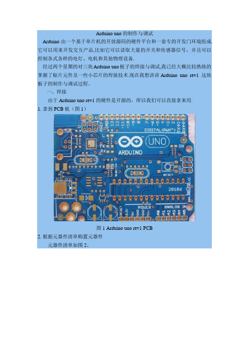
Arduino uno的制作与调试Arduino由一个基于单片机的开放源码的硬件平台和一套专的开发门环境组成.它可以用来开发交互产品,比如它可以读取大量的开关和传感器信号,并且可以控制各式各样的电灯、电机和其他物理设备.经过两个星期的对三块Arduino uno板子的焊接与调试,我已经大概比较熟练的掌握了贴片元件及一些小芯片的焊接技术.现在我想讲讲Arduino uno rev1 这块板子的制作与调试过程。
一、焊接由于Arduino uno rev1 的硬件是开源的,所以我们可以直接拿来用.1. 拿到PCB板(图1)图1 Arduino uno rev1 PCB2. 根据元器件清单购置元器件元器件清单如图2。
图2 元器件清单3. 焊接元器件根据图3来焊接元器件。
图3 PCB焊接图这里我想说说焊接的方法与技巧(供初学者参考).这块板子中还是有存在一些比较难焊的地方。
1)芯片ATmega8U2Arduino UNO与之前Arduino 2009版本的最大不同在于USB转串口部分,Arduino 2009采用的是FTDI专用芯片FT232RL,而Arduino UNO采用的是用一块ATmega8U2模拟出串口的做法.这一改动着实带来了不小的麻烦,第一是该方案所采用的ATmega8U2芯片基本上在市场上很难找到,另外一点就是该芯片的封装加大了焊接的难度和成本。
芯片ATmega8U2的封装很小,而且它芯片的外面没有引脚,可以看到的是它的焊盘非常的小。
焊接方法为:在各个焊盘上滴上锡,完了后检查一下有没有焊盘连接在一起的,然后用镊子夹住芯片ATmega8U2,小心的对准位置,对准后用镊子压住芯片,用电烙铁在一边的周围滑动加热,使得焊盘上的锡熔化,则芯片的引脚就焊在了焊盘上,同样的,其他三边也这样。
焊完之后用万用表检查一下。
2)贴片晶振及其他的贴片元器件因为左手是拿镊子夹住器件对准位置,右手拿电烙铁,所以没有另外的手来添加焊锡。
Arduino bootloader固件指导
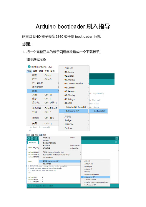
Arduino bootloader刷入指导这里以UNO板子去给2560板子刷bootloader为例。
步骤:
1.把一个完整正常的板子刷程序改造成一个下载板子。
如图选择示例
上传
至此编程工具改造完成。
2.拔掉USB线,直连线连接两个板子的6根线。
下面部分只是做个解释,可以忽略。
下图是2560的下载引脚定义
3.上电只需要给UNO板子插上USB即可,2560从UNO板子上取
电,不需要额外供电,也不需要插USB线。
给UNO板子插上USB,配置软件,板子选择2560,如图
点击烧录引导程序
此时UNO的板子会等闪烁,说明已经在烧录中,基本已经成功。
稍等不到20秒即可完成。
需要注意的就是UNO的SS引脚10(如果用其他的ARDUINO板子,其实就是SPI的SS这个信号)接在2560的Reset信号上。
上个实物图。
Arduino UNO是Arduino USB接口系列的最新版本
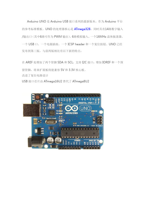
Arduino UNO是Arduino USB接口系列的最新版本,作为Arduino平台的参考标准模板。
UNO的处理器核心是ATmega328,同时具有14路数字输入/输出口(其中6路可作为PWM输出),6路模拟输入,一个16MHz晶体振荡器,一个USB口,一个电源插座,一个ICSP header和一个复位按钮。
UNO已经发布到第三版,与前两版相比有以下新的特点:在AREF处增加了两个管脚SDA和SCL,支持I2C接口;增加IOREF和一个预留管脚,将来扩展板将能兼容5V和3.3V核心板。
改进了复位电路设计USB接口芯片由ATmega16U2替代了ATmega8U2概要处理器ATmega328工作电压5V输入电压(推荐)7-12V输入电压(范围)6-20V数字IO脚14 (其中6路作为PWM输出)模拟输入脚6IO脚直流电流40 mA3.3V脚直流电流50 mAFlash Memory 32 KB (ATmega328,其中0.5 KB 用于bootloader)SRAM 2 KB (ATmega328)EEPROM 1 KB (ATmega328)工作时钟16 MHz电路图和PCB所有的参考设计是基于Atmega8,168,or 328,他们的管脚是兼容的电路图/en/uploads/Main/Arduino_Uno_Rev3-schematic.pdf硬件设计文件(Eagle文件)/en/uploads/Main/arduino_Uno_Rev3-02-TH.zip电源Arduino UNO可以通过3种方式供电,而且能自动选择供电方式外部直流电源通过电源插座供电。
电池连接电源连接器的GND和VIN引脚。
USB接口直接供电。
电源引脚说明VIN --- 当外部直流电源接入电源插座时,可以通过VIN向外部供电;也可以通过此引脚向UNO直接供电;VIN有电时将忽略从USB或者其他引脚接入的电源。
5V --- 通过稳压器或USB的5V电压,为UNO上的5V芯片供电。
Arduino UNO 样板调试
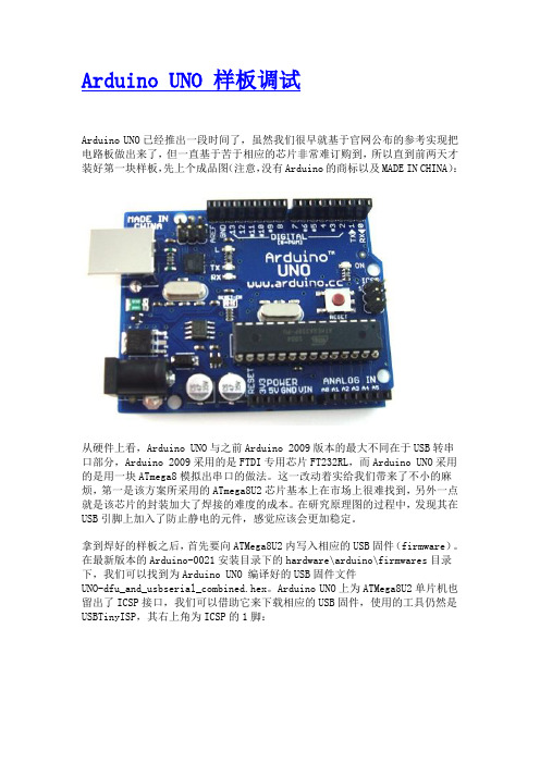
Arduino UNO 样板调试Arduino UNO已经推出一段时间了,虽然我们很早就基于官网公布的参考实现把电路板做出来了,但一直基于苦于相应的芯片非常难订购到,所以直到前两天才装好第一块样板,先上个成品图(注意,没有Arduino的商标以及MADE IN CHINA):从硬件上看,Arduino UNO与之前Arduino 2009版本的最大不同在于USB转串口部分,Arduino 2009采用的是FTDI专用芯片FT232RL,而Arduino UNO采用的是用一块ATmega8模拟出串口的做法。
这一改动着实给我们带来了不小的麻烦,第一是该方案所采用的ATmega8U2芯片基本上在市场上很难找到,另外一点就是该芯片的封装加大了焊接的难度的成本。
在研究原理图的过程中,发现其在USB引脚上加入了防止静电的元件,感觉应该会更加稳定。
拿到焊好的样板之后,首先要向ATMega8U2内写入相应的USB固件(firmware)。
在最新版本的Arduino-0021安装目录下的hardware\arduino\firmwares目录下,我们可以找到为Arduino UNO 编译好的USB固件文件UNO-dfu_and_usbserial_combined.hex。
Arduino UNO上为ATMega8U2单片机也留出了ICSP接口,我们可以借助它来下载相应的USB固件,使用的工具仍然是USBTinyISP,其右上角为ICSP的1脚:下载时使用的命令为:avrdude -p at90usb82 -F -P usb -c usbtiny -Uflash:w:UNO-dfu_and_usbserial_combined.hex-U lfuse:w:0xFF:m -U hfuse:w:0xD9:m -U efuse:w:0xF4:m -U lock:w:0x0F:m有意思的是写入USB固件时标明的芯片类型为AT90USB82,这显然与板子上使用的ATMega8U2不同,下载过程中avrdude也提示了这一点,估计两者的功能是比较类似的,或者就是同一芯片的不同版本罢了。
Arduino UNO R4 MiniMA ABX00080说明书

1122334455667788DDCCBBAAReference Designs ARE PROVIDED "AS IS" AND "WITH ALL FAULTS. Arduino SA DISCLAIMS ALL OTHER WARRANTIES, EXPRESS OR IMPLIED, REGARDING PRODUCTS, INCLUDING BUT NOT LIMITED TO, ANY IMPLIED WARRANTIES OF MERCHANTABILITY OR FITNESS FOR A PARTICULA R PURPOSE.Arduino SA may make changes to specifications and product descriptions at any time, without notice. The Customer must not rely on the absence or characteristics of any features or instructions marked "reserved" or "undefined".Arduino SA reserves these for future definition and shall have no responsibility whatsoever for conflicts or incompatibilities arising from future changes to them. The product information on the Web Site or Materials is subject to change without notice.Do not finalize a design with this info. ARDUINO and other Arduino brands and logos and Trademarks of Arduino SA. All Arduino SA Trademarks cannot be used without owner's formal permission.11UNO R4 MINIMA ABX00080V1.04/24/20233:04:30 PM Title:ID:Date:Version:Sheet of Time:Silvio NavarettiAuthor:RevAuthor:Silvio NavarettiTOP.SchDocFile:330R14330R15DL1KPT-1608YC YELLOWDL2KPT-1608YC TX LED RX LED MICROCONTROLLER330R16DL3HSMG-C190POWER LED+5VP012YELLOWFiducial_1Fiducial_2GREENP400/GTIOC6A1P401/GTIOC6B/CTX02P402/CRX03VBATT 4VCL5P215 INPUT ONL Y/XCIN 6P214 INPUT ONL Y/XCOUT7VSS 8P213/GTIOC0A/XTAL 9P212/GTIOC0B/EXTAL10VCC 11P411/GTIOC6A12P410/GTIOC6B 13P409/GTIOC5A/USB_EXICEN 14P408/GTIOC5B/USB_ID15P407/USB_VBUS/ADTRG016VSS_USB 17P915/USB_DM 18P914/USB_DP19VCC_USB20VCC_USB_LDO 21P20622GTIOC4A/P20523GTIOC4B/P20424RES25MD/P20126NMI/INPUT ONL Y P20027GTIOC7A/P30428GTIOC7B/P30329GTIOC4A/P30230GTIOC4B/P30131P300/GTIOC0A/TCK/SWCLK 32P108/GTIOC0B/TMS/SWDIO 33CTX0/TDO/SWO/GTIOC1A/P10934CRX0/TDI/GTIOC1B/P11035GTIOC3A/P11136GTIOC3B/P11237GTIOC2A/P11338VCC 39VSS40GTIOC0A/P10741GTIOC0B/P10642GTIOC1A/P10543GTIOC1B/P10444GTIOC2A/AN019/P10345ADTRG0/GTIOC2B/AN020/P10246GTIOC5A/AN021/P10147GTIOC5B/AN022/P10048GTIOC2A/AN016/P50049GTIOC2B/AN017/P50150GTIOC3B/AN018/P50251AN010/P01552DA0/AN009/P01453VREFL/AN008/P01354VREFH/AN007/P01255AVCC056AVSS057VREFL0/AN006/P01158P010/AN005/VREFH059AN004/P00460AN003/P00361AN002/P00262AN001/P00163AN000/P00064U1R7FA4M1AB3CFM#AA0USB_D_N USB_D_P15pFC113N C2N C4Y1FTX16.000M12SM3S-30/3015pFC3RESET +5V 4.7µFC4100nF C5100nFC6VCC_USB is the output of theinternal USB LDO providing 3V3 to the peripheralRefer to figure 26.4 page 555 of the user manual4.7µFC7AREF+5VL1BLM18PG471SN1D5.1kR4VREFH01µFC9L2BLM18PG471SN1D100nF C8VCL is the output of the internal LDO4.7µFC11RESET PUSHBUTTONHEADERS+5V+5VUSB5.1kR1 5.1kR25.1kR3SCL18SDA 17AREF 16GND 15D13/SCK 14D12/MISO 13D11/MOSI 12D10/CS11D910D89D78D67D56D45D34D23D1/TX 2D0/RX1JDIGITAL20TW-994C2DNP12345PB11571636-3AREFNC 1IOREF 2RESET 33V345V5GND6GND7VIN 8A09A110A211A312A413A514JANALOG20TW-995RESET RESET112233445566J1PH2-06-UA+5V P013USB CONNECTORSHIELD1GNDB12VBUS B9SBU2B8D-B7D+B6CC2B5VBUS B4GND B1GND A12VBUSA9SBU1A8D-A7D+A6CC1A5VBUS A4GND A1FIXING A12A1B12B1SHIELD2SHIELD3SHIELD4J3CX90B-16P VBUS_CONN CC1USB_D_PUSB_D_N D-USB USB_D_N USBUSB_D_P D+CC2GND21MR231kV4.7nFC21ESDPROTECTION2341D4PRTR5V0U2X,215SHIELD2CC RESISTORS CC2CC15.1kR24 5.1kR25123J419TW-746+5VUSB LDO OUTPUT+3V3100nF C10+5VVINDC SHIELD2USB_D_N USB_D_P SWD CONNECTOR12345678910J2HPH2-A-10-SGARESET +5VRXTX RTS CTSSCI15.1kR75.1k R85.1kR9P012P0135.1kR5 5.1kR6INPUT ONLY+3V3VIN DAC OPAMP+P000_AN00_AMP+OPAMP-OPAMP OUT P014_AN09_DAC P001_AN01_AMP-P002_AN02_AMPO P101_AN21_SDA P100_AN22_SCL P000_AN00_AMP+P001_AN01_AMP-P002_AN02_AMPOP014_AN09_DACP100_AN22_SCL P101_AN21_SDA P100_AN22_SCL P101_AN21_SDAP301_SCI2_RXDP302_SCI2_TXD P301_SCI2_RXD P302_SCI2_TXD I2C PULLUPSNOT MOUNTEDP105_IRQ00_GPT1_A P105_IRQ00_GPT1_A DL4KPT-1608YC YELLOW 330R17SCK LEDP104_IRQ01_GPT1_B P104_IRQ01_GPT1_B P103_SPI0_SSL_GPT2_A_CAN0_TX P103_SPI0_SSL_GPT2_A_CAN0_TX P102_SPI0_RSPCK_GPT2_B_CAN0_RX P102_SPI0_RSPCK_GPT2_B_CAN0_RX P106_GPT0_BP106_GPT0_B P107_GPT0_A P107_GPT0_AP304_GPT7_A P304_GPT7_AP303_GPT7_B P303_GPT7_B P112_GPT3_BP112_GPT3_B P109_SCI9_TXD P109_SCI9_TXD P109_SCI9_TXDP110_SCI9_RXD P110_SCI9_RXD P 110_S C I 9_R X DP111_GPT3_A P111_GPT3_A P 111_G P T 3_AP111_GPT3_AP108_SWDIO P300_SWCLK P108_SWDIOP300_SWCLK P501_SCI1_TXD P502_SCI1_RXDP501_SCI1_TXDP502_SCI1_RXD +5VMD MDVUSBDCJACKBUCKCONVERTERSCHOTTKY FORREVERSE POLARITY PROTECTIOND3PMEG6020AELRXD2PMEG6020AELRXSS 1SYNC2BOOT 3VIN 4PHASE5PGND 6EN 7PG 8VCC 9FB 10COMP11FS12GNDPAD13U2ISL854102FRZ-T +5V2.3A 10µH L3PMF42-103MN100nF C1225V 22µF C130R12100kR1325V22µFC1825V 22µF C1525V 22µF C1633pF C1425V 22µF C171µFC2025V22µF C1913.7kR180R20249kR19100kR21100kR221nFC22100pFC23+5V+5V VUSB VUSB VUSBVUSB VUSB 0R11100k 0.1%R1013.7k 0.1%R26+5VSCHOTTKY FOR USB OVERVOL TAGE PROTECTIONP204LOVE。
手把手教你写STM32的bootloader(SDIO读取TF更新Bootloader)

手把手教你写STM32的bootloader(SDIO读取TF卡更新固件)作者:谭建裕1、bootloader的简介及作用什么是bootloader?本人不知道该怎么说,反正会来看这篇都是知道自己要干嘛的。
不过bootloader的作用还是要提提的,bootloader最直观的作用就方便,比如你用单片机给人家做了一款产品,后期你的产品固件需要更新的时候,你总不能带着电脑直接去客户那里拆开产品给单片机下程序吧?也不能教客户怎么给单片机下程序吧?用户体验感太差。
其实本质上bootloader的也是一个完整的程序,也有main函数,有自己的中断向量表,栈顶指针,它可以检查有没有新的固件,如果有,则将新的固件的数据写入到我们指定的flash地址中,之后跳到新的程序中去就OK了。
此时bootloader的优势就来了,bootloade 更新固件有很多种方式,本人在这里只详细讲解一种,搞懂一种之后,其它的都好办,因为它们的思路都是一样的。
Bootloader的主体原理是:首先将bin文件的数据复制到特定的地址。
然后设置中断向量表,设置MSP主堆栈指针(具体请看CM3权威指南),设置复位向量。
然后就没有然后了。
2、bootloader涉及的知识本人在此讲解的是STM32通过读取TF内的bin文件数据来更新固件。
这里牵扯到STM32的SDIO外设,FATFS文件系统,STM32的flash读写操作。
2.1 SDIOSDIO是STM32的外设,需要注意的是只有100引脚及以上的才有。
电路原理图如图2-1-1所示。
图2-1-1注意:在使用TF之前必须保证TF卡格式为FAT32,单元大小为2048。
如图2-1-2所示。
图2-1-2记得在stm32f10x_it.c文件中添加中断函数。
如图2-1-3所示。
图2-1-32.2 FATFS文件系统移植和使用文件系统使用的是FATFS9,源码在压缩包的ff9文件夹,如图2-2-1所示。
CT-UNO 用户手册说明书

CT-UNOCT UNO (Arduino Uno Compatible)User's ManualV1.0Nov 2014INDEX1.Introduction 32.Packing List 43.Product Specification 54.Dimension 65.Board Layout 76.Hardware Installation97.Getting Started138.Warranty15CT-UNO is a Cytron version of Arduino Uno.This board combines the simplicity of the UNO’s Optiboot bootloader(which load program faster),the stability of the FTDI and the R3 shield compatibility of the latest A rduino UNO R3.CT-UNO has all the amazing features Arduino UNO offer.14Digital I/O pins with6PWM pins,6Analog inputs,UART,SPI,external interrupts,not to forget the I2C too.The SDA, SCL and IOREF pins which being broken out on UNO R3are on CT-UNO too.We has also populated the ISP header pins(SPI and power).With this,CT-UNO will be compatible with all Arduino UNO's shield.CT-UNO comes with following features:●SMD ATmega328 microcontroller with Optiboot (UNO) Bootloader.●USB Programming Facilitated by the Ubiquitous FTDI FT231X (more stable).●Input voltage: DC7-15V.●On board 1A (maximum) 5V voltage regulator.●On board 500mA (maximum) 3.3V voltage regulator.●0-5V digital outputs with 3.3V compatible inputs.●14 Digital I/O Pins (6 PWM outputs).● 6 Analog Inputs (Can be digital I/O too).●ISP 6-pin Header.●32k Flash Memory.●16MHz Clock Speed.●R3 Shield Compatible.●TX, RX, Power, pin 13 LEDs are moved to edge.●Utilize USB Micro-B socket.●White PCB!Please check the parts and components according to the packing list.If there are any parts missing, please contact us at s***************.my immediately.CT-UNO comes with:● 1 x C T-UNO board.Optional add-on:●12V 2A AC to DC Adapter●USB Micro B cableCT-UNO is designed to offer starting up platform for development. The specification of ATmega328p used should be referred.Absolute Maximum RatingParameter Min Max Unit Input Voltage via Adapter (Recommended)7 15 V Input Voltage via Adapter (Limits) 6 20 V I M AX (5V) (from on-board 5V Voltage regulator)*- 1 A I M AX (3.3V) (from on-board 3.3V Voltage regulator) - 500 mA * With Vin at 12VLABEL DESCRIPTIONA Reset ButtonB Micro USB B Type Connector (Female)C RX LED Indicator (Serial)D TX LED Indicator (Serial)E Programmable LEDF Power LED IndicatorG Adapter Socket (2.1mm)H Extra PadsI Arduino R3 Standard HeaderJ ISP Header PinReset ButtonReset button can be used to reset/restart the CT-UNO program.Micro USB B Type Connector (Female)This connector is for USB connection to upload program or power up via USB cable.A USB micro-B type cable is needed.RX LED Indicator (Serial)RX LED lights up when there have data transfer from USB to ATmega328.TX LED Indicator (Serial)TX LED lights up when there have data transfer from ATmega328 to USB. Programmable LEDProgrammable LED is active HIGH and it is connected to pin 13.Power LED IndicatorPower LED will light ON once the board is powered.Adapter Socket (2.1mm)DC power adaptor socket for user to plug in DC adapter.The input voltage should be ranged from 7 to 15V.Extra PadsThis extra pad allow CT-UNO to be stacked on strip/donut board.Arduino R3 Standard HeaderCT-UNO can be stacked with Arduino shield.ISP Header PinUser can upload Arduino Uno bootloader firmware using AVR programmer(e.g.AVR USBasp) through this pin.6.1 CT-UNO power supplyCT-UNO power source is either from 12V power adapter(via DC jack) or U SB cable. If CT-UNO is powered using both supply (12V adapter and USB cable) it will automatically choose power from adapter.●CT-UNO is being powered using adapter.●CT-UNO is being powered using USB cable.●If C T-UNO is powered with both 12V Power adapter and USB cable, it willautomatically choose power from power adapter.6.2 Downloading bootloader firmwareCT-UNO provide ISP for user uploading Arduino Uno bootloader firmware. User can use AVR programmer (e.g. A VR USBasp) to upload firmware to ATmega328p.6.3 Interface CT-UNO●CT-UNO is Arduino Uno compatible, so it can be stacked with all Arduino UNOcompatible shields. Below is example L CD Keypad shield stacked onto CT-UNO.●This is example of wireless remote mobile omni robot that uses CT-UNO,SHIELD-XBEE and FD04A-R2 board.●CT-UNO can also be stacked onto standard (0.1” pitch to pitch) s trip/d onut board. Userneed to solder header pins at outer side (left and right) to stack CT-UNO onto strip/donut board.7. GETTING STARTED7.1 Get a CT-UNO board and USB cableYou will need a C T-UNO and U SB Micro B Cable to start.7.2 Download the Arduino EnvironmentGet the latest Arduino IDE from h ttp:///en/Main/Software.When the download finishes,unzip the downloaded file.Make sure to preserve the folder structure.Double-click the folder to open it.There should be a few files and sub-folders inside.7.3 Connect the CT-UNOCT-UNO automatically draw power from either the USB connection to the computer or an external power supply.To start,just connect CT-UNO board to laptop/computer using U SB micro B cable. The PWR LED (green) will light up to indicate the board are being powered.7.4 Install the drivers●Plug in your board and wait for Windows to begin it's driver installation process.After afew moments,the process will fail,despite its best efforts.If the driver installation succeed, it means you already use FTDI device with your computer before.●In the case of fail,you can download the latest FTDI driver on FTDI website.Chooseappropriate operating system.(h ttp:///Drivers/VCP.htm).After download is complete, proceed with the installation.●If the driver installation succeed,you should have the COM port number for yourCT-UNO board.7.5 Launch the Arduino IDEDouble click on arduino.exe.7.6 Open blink exampleGo to F iles-> E xamples-> 01.Basics-> B link.7.7 Select your boardGo to T ools-> B oard->A rduino Uno.7.8 Select CT-UNO serial port numberGo to T ools-> S erial Port-> select your CT-UNO COM port number.7.9 Upload the program●Now,simply click the"Upload"button in the environment.Wait a few seconds-youshould see the RX and TX leds on the board flashing.If the upload is successful,the message "Done uploading." will appear in the status bar.●A few seconds after the upload finishes,you should see the pin13(L)LED on the boardstart to blink(in orange).If it does,congratulations!You've gotten CT-UNO up-and-running.8. WARRANTY●Product warranty is valid for 12 months.●Warranty only applies to manufacturing defect.●Damaged caused by misuse is not covered under warranty●Warranty does not cover freight cost for both ways.Prepared by:Cytron Technologies Sdn. Bhd.No. 16, Jalan Industri Ringan Permatang Tinggi 2,Kawasan Industri Ringan Permatang Tinggi,14100 Simpang Ampat,Penang, Malaysia.Tel:+604 - 504 1878Fax: +604 - 504 0138URL: .myEmail: s*****************.my****************.my。
外文翻译---Arduino Uno 参考手册

外文翻译---Arduino Uno 参考手册摘要本参考手册是为Arduino Uno开发板设计的, 它提供了关于Arduino Uno的详细信息, 包括硬件规格和操作指南。
介绍Arduino Uno是一款基于开源原理设计的微控制器开发板。
它是Arduino官方的入门级产品,用户友好且易于使用。
该开发板基于ATmega328P微控制器,具有14个数字输入/输出引脚、6个模拟输入引脚、一个16 MHz的晶振、一组串行通信接口以及其他功能。
硬件规格- 处理器: ATmega328P- 工作电压: 5V- 输入电压: 7-12V- 输入电压(极限): 6-20V- 数字I/O引脚数量: 14(其中6个支持PWM输出)- 模拟输入引脚数量: 6- 直流电流每个I/O引脚: 20 mA- 直流电流总共I/O引脚: 200 mA- 内存容量: 32 KB (其中 0.5 KB 用于引导程序)- SRAM容量: 2 KB- 闪存容量: 1 KB- 时钟频率: 16 MHz操作指南以下是Arduino Uno的一些基本操作指南:2. 连接Arduino Uno。
将Arduino Uno通过USB电缆连接到计算机。
3. 选择Arduino Uno开发板。
在Arduino IDE的工具菜单中,选择正确的开发板和端口。
4. 写入代码。
使用Arduino IDE编写您的代码,并使用“上传”按钮将代码上传到Arduino Uno。
5. 运行代码。
一旦代码成功上传,Arduino Uno将开始执行您的程序。
6. 调试和测试。
根据您的需求对代码进行调试和测试,以验证Arduino Uno是否按预期工作。
结论本参考手册提供了关于Arduino Uno的详细信息,包括硬件规格和操作指南。
使用本手册可以更好地了解和操作Arduino Uno开发板。
Note: This Chinese translation is for reference only and should be validated by a professional translator before use.。
新手帖用ARDUINO给MEGA2560刷BOOT

新手帖用ARDUINO给MEGA2560刷BOOT 本帖最后由 darkorigin 于 2013-5-12 00:50 编辑首先对张老师在之前28J60模块调试中给予的帮助以及在此次刷BOOTLOADER中给予的帮助表示感谢!之前一直怀疑自己的2560因为BOOT版本的原因导致28J60工作不正常接着由于这个小项目的推进,购买了张老师的mircoduino以及其他模块若干(由于和此文无关暂且带过不表)接着在论坛里面搜索了2560的刷BOOT过程(中间还无耻的拜了度娘),于是发现不管是各位大神还是各大论坛的ARDUINO教程中刷写ARDUINO主要集中在328P以及其他更廉价的模块,甚至是AVR芯片本身(于是各种构建于面包板的ARDUINO诞生了)唯独看不见的就是1280以及2560的相关刷法。
经过了请教zcbzjx ,看ARDUINO的图纸,参考2560图纸,等等过程,算是绕了很多圈圈,最终将2560的BOOT成功的刷进去了。
备注: 以下称UNO(用来做ARDUINO刷写器的板子)为 UNO ,待刷的板子称作 MEGA;下面贴出我实现的过程:材料 :mircoduino (其他所有兼容UNO的模块均可) 作为ARDUINO ISP例程的载体ARDUINO 2560mega (1280同2560 刷法一样) 作为待刷BOOTLODER的ARDUINO杜邦线(其实就是做实验的面包板线)6根刷写过程:1. 首先使用ARDUINO 最新版本的IDE 打开FILE - Examples - Arduino ISP 并且按照文末的提示修改代码(算是一个小BUG)2. 按照连接图连接好主从机(就是UNO和MEGA连接的关系),一定要确认之后再进行连接(连接过程之前拔掉2块板子的供电和COM口,仔细确认后UNO连接USB供电此时MEGA已经不需要外部电源了,直接由UNO供电和重启),有些错误将导致硬件损坏;3.检查你的COM口设置。
怎么使用USBasp给arduino烧写bootloader?
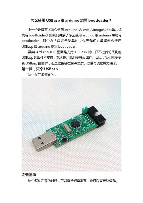
怎么使用USBasp给arduino烧写bootloader?上一个教程其《怎么使用Arduino给AVR(ATmege328p)单片机烧写bootloader》实我们讲解了怎么使用arduino给arduino来烧写bootloader,那个方法应该是简单的,今天我们来看看怎么使用USBasp给arduino烧写bootloader。
其实Arduino IDE里面是支持USBasp的,只不过我们买到的USBasp的固件不支持,就会提示我们要升级固件。
因此,我们需要更新USBasp的固件,但是过程稍微有点复杂。
以后再说这种方法了。
第一步,买个USBasp这个东西很便宜的,安装驱动这个驱动在买的时候,可以直接问卖家要,也可以直接私信我。
硬件连线左边是usbasp的图,右边是arduino icsp口的图,对应连接就好了。
软件设置打开智峰progisp软件(可以私信我获取,也可以自己去网上下载)。
我们以arduino uno为例,由于arduino uno使用的是ATmega328P芯片,因此在Select Chip一栏选择ATmega328P,然后点击RD按钮。
如果提示'读出ID成功',说明你的芯片和连线都是OK的。
找到bootloader的hex文件。
此文件需要看boards.txt说明,地址在arduino-1.0.5-r2\hardware\arduino文件夹中打开它,你可以看到配置文件,根据配置文件,你可以找到hex 文件所在路径,以及熔丝位的配置设置熔丝位,点击progisp软件的“自动”按钮右边的“...”按钮,调出熔丝位设置界面,按照boards.txt所述修改好熔丝位。
烧写完熔丝位后,烧写hex文件。
按照boards.txt所述,我们调入bootloader的hex文件,方法是:在软件右边的文件栏下,点击调入flash按钮,然后打开hex文件,根据boards.txt文件,在arduino-1.0.5-r2\hardware\arduino\bootloaders\optiboot文件夹中的optiboot_atmega328.hex文件。
Arduino嵌入式系统的开发与应用
目录摘要: (2)1.Arduino 简述 (3)1.1Arduino嵌入式系统的概念 (5)1.2 Arduino功能特点 (7)1.3基本结构 (10)2.Arduino嵌入式系统的应用实例 (15)-------基于Arduino的简易亮光报警器的设计与实现. (15)2.1ATmega单片机 (16)2.2光敏电阻介绍 (16)2.3 工作原理 (17)2.4设计与实现.................................................................................. 错误!未定义书签。
2.4.1 实验器件......................................................................... 错误!未定义书签。
2.4.2 实验连线......................................................................... 错误!未定义书签。
2.4.3 实验原理......................................................................... 错误!未定义书签。
2.4.4 下载程序......................................................................... 错误!未定义书签。
2.4.5 功能验证......................................................................... 错误!未定义书签。
2.4.6 程序代码......................................................................... 错误!未定义书签。
Eclipsehelios上编写arduino程序并进行烧录

Eclipsehelios上编写arduino程序并进行烧录刚接触arduino,很不错。
arduino 的ide我一开始使用的是0022版本,它的编辑器实在是难受,没有提示没有自动补全,由于一直使用eclipse开发,就找找办法了。
我的板子是 Arduino UNO..按照官方的办法,无果。
按照arduino.tw的办法,无果...最终,终于找到一个办法,在无尽的折腾中,终于搞定了,下面是Arduino UNO的配置步骤:准备工作:* Eclipse CPP (我的版本是 eclipse-cpp-helios-SR2-win32)* AVR Eclipse Plugin (我的版本是 avreclipse-p2-repository-2.3.4.20100807PRD)* WinAVR (我的版本是 WinAVR-20100110)* Arduino IDE (我的版本是 arduino-0022)Step 1 --配置arduino编译环境:第一步:(嫌麻烦,可以直接跳到第二步)依次装好winAvr和eclipse-cpp后,把下载到的avr eclipse plugin这个压缩包解压,放到eclipse/dropins这个目录里,重启eclipse后,就会有avr的选项了。
首先进入eclipse的属性设置:然后在avr的path选项,会像这样,路径是你的安装路径,如图,AVR-GCC,GNU make,AVR header files都是winavr的路径,自己推算然后导入这个工程,首先是为了各种gcc 参数的简化配置,自己从头来的话,配置很麻烦,直接导入很省事,只要少量更改。
其次,这个工程是编译arduino core这个库文件,以后编译arduino工程的时候,就不用手动导入那么多头文件了。
下载:ArduinoCore.rarimport导入工程后,要对工程属性进行一些更改,工程->右键->属性把target hardware的参数配置成这样:MCU type:ATmega328PMCU Clock Frequency:16000000 (六个〇)然后设置工程引入的库文件,还是在工程的属性设置里C/C++ Build->Setting将要对AVR Complier和AVR C++ Complier的Directories 设置,目录就是Arduino IDE下面相关的路径,请看图:两个路径设置是相同的至此,就可以编译了,点击 project -> make all ,eclipse应该可以编译成功,输出如下:****Clean-only build of configuration Release for project Blinky ****make cleanrm -rf ./main.o Blinky.eep Blinky.hex Blinky.lss ./main.d sizedummy Blinky.elf**** Build of configuration Release for project Blinky ****make allBuilding file: ../main.cppInvoking: AVR C++ Compileravr-g++-I"D:\Program Files\arduino-0022\hardware\arduino\cores\arduino" -Wall -Os -fpack-struct -fshort-enums -funsigned-char-funsigned-bitfields -fno-exceptions -mmcu=atmega328p -DF_CPU=16000000UL -MMD -MP -MF"main.d" -MT"main.d" -c -o"main.o" "../main.cpp"Finished building: ../main.cppBuilding target: Blinky.elfInvoking: AVR C++ Linkeravr-gcc --cref -s -Os -o"Blinky.elf" ./main.o -lArduinoCore -lm -Wl,-Map,Blinky.map,--cref -L"C:\Users\hang\Desktop\Blinky" -mmcu=atmega328pFinished building target: Blinky.elfInvoking: AVR Create Extended Listingavr-objdump -h -S Blinky.elf >"Blinky.lss"Finished building: Blinky.lssCreate Flash image (ihex format)avr-objcopy -R .eeprom -O ihex Blinky.elf "Blinky.hex"Finished building: Blinky.hexCreate eeprom image (ihex format)avr-objcopy -j .eeprom --no-change-warnings --change-section-lma .eeprom=0 -O ihex Blinky.elf "Blinky.eep"Finished building: Blinky.eepInvoking: Print Sizeavr-size --format=avr --mcu=atmega328p Blinky.elfAVR Memory Usage----------------Device: atmega328pProgram: 7594 bytes (23.2%Full)(.text+ .data + .bootloader)Data: 202 bytes (9.9%Full)(.data + .bss + .noinit)Finished building: sizedummy复制代码在工程的 Release目录下会有一个 libArduinoCore.a 文件生成,这个就是编译好的库文件,以后用得着。
研究arduino支持Atmega8作为主控制芯片
研究arduino支持Atmega8作为主控制芯片arduino uno 相对于duemilanove 的一个显著变化就是其bootloader,uno 使用了新版的bootloader 后,同样是328P 芯片,使用空间有32256 字节,而duemilanove 只有30720 字节。
新版的bootloader 叫做Optiboot,是国外某位大侠觉得老版bootloader 太过古董了,小宇宙爆发,就写了出来。
新版bootloader 的主要特点1,可用空间大了,比起原来2K 的体积,减少了接近1.5KB。
(对于NG 的古董bootloader 也缩小了0.5K)2,上传程序速度更快,新版的bootloader 波特率是115200。
3,对代码进行了优化,提高了运行效率,而且无看门狗问题。
4,支持使用ATMEGA8 168 328 芯片的arduino,未来可能会支持更多芯片。
可是现在的arduino IDE 中,不管是ng,nano 等老于uno的板子,还是一成不变的默认下载老bootloader,跟不上时代了。
自己动手丰衣足食,先解决最古董的ATmega8 芯片,其他的就好说了。
先到arduino 官方下载回来最新版本的optiboot。
以arduino 0022 为例,为了更接近官方的那么简单的下载方法,我们先把解压缩出来的两个文件optiboot_atmega8.hex 与optiboot_atmega8.lst 放入arduino-0022hardwarearduino ootloadersop tiboot中。
然后打开arduino-0022hardwarearduino oards.tx t文件,在文件末尾下上下面代码。
##############################################################opti8.na me=ArduinoOptiboot8opti8.upload.protocol=stk500opti8.upload.maximum_size=7680opti8.uploa d.speed=115200opti8.bootloader.low_fuses=0xbfopti8.bootloader.high_fuses=0xcco pti8.bootloader.path=optibootopti8.bootloader.file=optiboot_atmega8.hexopti8.bootl。
