KEKO安装指南
Joker安装说明手册-new

SK软硬件安装指导手册V1.2

图 2-10
图 2-11
图 2-12
2)安装 SK-SYS 软件
打开 SK 光盘,双击运行 SK_SETUP 安装包后,软件会自动安装在 C:\Program Files\SK 目录下,整个过程采用无人值守方式安装,无需人工干预。安装完毕后,会在 桌面和快速启动栏中出现 SK 的快捷方式如图 2-12。
图 2-1
图 2-2
2、在图 2-3 界面 ,双击“Internet 协议(TCP/IP) ” ,弹出如图 2-4 界面,输入 IP 地址如图 2-4 所示,填写完成,单击【确定】按钮。 (注意:客户端电脑 IP 配置方法与之相同,在此不在陈述。配置客户 端电脑时,在图 2-4 界面的“IP 地址(I) ”栏输入“192.168.1.3” 即可,其它不变) 。
14、选择“使用本地系统账号“,单击【下一步】按钮
15、选择“混合模式” ,在密码框内输入密码“8201” ,单击【下一步】 按钮。 ★ 注意: 密码必须是“8201” ,切不可输错。
第
13 页
机器人电子-----专注铸就品质-共赢成就未来
SK 系统软硬件安装指导 V1.2
16、单击【下一步】按钮
机器人电子-----专注铸就品质-共赢成就未来
SK 系统软硬件安装指导 V1.2
一 : SK 场 地 管 理 系 统 典 型 应 用 方 案 介 绍
服务器 远程账 目查询 客户端电脑 机器人电子
短信猫
手机 图例说明: 网线
主交换机
H3C
○ ○ ○
E 网吧台售币机 E 网存取一体机 E 网存币机 E 网提币机 E 网存票机
软件安装步骤如下:
1)安装 DATASERVER 软件
Kwikset Halo Touch Fingerprint Smart Lock 安装和参考指南说
English 66856Rev 01Installation and Reference Guide/halo-touch/app1T able of contentsParts in the box (4)Required tools (5)Installation (7)Download the app (17)Reference guide (19)3Parts in the boxExterior assemblyBattery pack 457931011Install the interior assembly4Remove the interior cover from the interior assembly.Create your account/appThe Kwikset app is needed to use this lock. If this lock was professionally installed (or installed by someone other than the homeowner), make sure this step is performed by the homeowner.Follow the setup instructions in the Kwikset app to create your account:17T o lock your door, placeon the fingerprint sensor. The light bar will display the following animations, beep once, and the LockingOrange sweep, moving toward door edgeAll LEDsblue duringauthenticationAll LEDsorange for2 secondsGreen sweep,moving awayfrom door edge.All LEDsgreen for2 secondsEnabling Amazon Alexa Enabling Google AssistantFollow the setup instructions to enable Amazon Alexa:Follow the setup instructions to enable Google Assistant:Amazon Alexa Guide Google Assistant GuideLockingBlue :Authenticating fingerprint Low battery or door jamUnlockingDevice Compatibility Router CompatibilityPlease see theDevice Compatibility list to see if your device is compatible.Please see the Router Compatibility list to see if your router is compatible.Device Compatibility Router CompatibilityNOTE: Halo T ouch implementsa standard based Wi-Fi radioand should work with majorityof the routers available in themarket that are Wi-Fi certified.Manual Door HandingIf needed, the door handing process can be initiated manually. This is useful if the lock is being moved to a different door.Factory Reset will:• delete all Wi-Fi settings • delete user associations • reset all lock settingsincluding handing• delete access codes and event history from thelock. Note: They will stillappear in the app andcloud until the lock isdeleted from the app.Factory reset should beused when:• you want to change the lock owner• you have lost your phone • you are troubleshooting ona new installationFactory ResetHalo T ouch at a GlanceExteriorInterior(cover removed)sensor Button “B”Program buttonTurnpiece shaftBattery pack29Important SafeguardsRegulatory Compliance1. Read all instructions in their entirety.2. Familiarize yourself with all warning and caution statements.3. Remind all family members of safety precautions.4. Always have access to your lock’s standard key.5. If using the Auto-Lock features, make sure you have your smartphone or standard key with you to prevent locking yourself out.6. Familiarize yourself with all light bar error notifications.7. Replace low batteries immediately.8. Dispose of used batteries according to local laws and regulations.WARNING: This Manufacturer advises that no lock can provide complete security by itself. This lock may be defeated by forcible or technical means, or evaded by entry elsewhere on the property. No lock can substitute for caution, awareness of your environment, and common sense. Builder’s hardware is available in multiple performance grades to suit the application. In order to enhance security and reduce risk, you should consult a qualified locksmith or other security professional.This product complies with standards established by the following regulatory bodies:• Federal Communications Commission (FCC)• Industry CanadaFCC This device complies with Part 15 of the FCC Rules. Operation is subject to the following two conditions: ( 1 ) this device may not cause harmful interference, and ( 2 ) this device must accept any interference received, including interference that may cause undesired operation.This equipment has been tested and found to comply with the limits for a Class B digital device, pursuant to Part 15 of the FCC Rules. These limits are designed to provide reasonable protection against harmful interference in a residential installation. This equipment generates, uses, and can radiate radio frequency energy and, if not installed and used in accordance with the instructions, may cause harmful interference to radio communications. However, there is no guarantee that interference will not occur in a particular installation. If this equipment does cause harmful interference to radio or television reception, which can be determined by turning the equipment off and on, the user is encouraged to try to correct the interference by one or more of the following measures:• Reorient or relocate the receiving antenna.• Increase the separation between the equipment and receiver.• Connect the equipment into an outlet on a circuit different from that to which the receiver is connected.• Consult the dealer or an experienced radio/TV technician for help.IMPORTANT! Changes or modifications not expressly approved by the manufacturer could void the user’s authority to operate the equipment.Industry Canada This device contains licence-exempt transmitter(s)/receiver(s) that comply with Innovation, Science and Economic Development Canada’s licence-exempt RSS(s). Operation is subject to the following two conditions: ( 1 ) This device may not cause interference, and ( 2 ) This device must accept any interference, including interference that may cause undesired operation of the device.。
KK002 快速安装指南说明书
4
6. Instructions for the icons and buttons on live video page: Pan/tilt control Slither the video to pan or tilt the camera
Allows User to listen to the camera's audio feed and talk to the camera. Take snapshots and record video files.
720P Version 1.0.2 EN
HD
IP Camera KK002
Quick Start Guide
Shenzhen Keekoonvision Technology Co., Ltd
Table of Contents
What’s In the Box.................................................................... 1 Get Started.................................................................................... 1 Hardware Installation.................................................................. 2 For Mobile Device....................................................................... 3 Set Up Camera............................................................................. 6 View in Windows Web Browser.............................................. 8 View in Windows CMS Software.............................................. 11 FAQ......................................................................................nge the speed of the pan/tilt of the camera. There Pan/Tilt Speed are 5 options: Fastest, Fast, Normal, Slower and Slowest.
K2同步软件安装过程

手机TF卡连接电脑
K2 插TF卡连接电脑过程首先手机要有插TF卡在内就可以操作第一步手机操作进入手机主菜单选择工具箱中的USB 大容量储存这个时候手机提示连接电脑使用数据线连接电脑连接电脑后会提示新的硬件这时要用光盘中的BOOT 中的USB 驱动文件电脑提示寻找驱动时可以通过光盘路径自己手动寻找到
BOOT 中的USB 驱动文件夹. 安装完USB驱动后在我的电脑中就有一个新的盘手机会自动生成3个文件夹一般听歌的朋友只要把歌曲放在MUSIC的文件夹就可以了
手机同步软件
K2 驱动安装过程先在光盘中的B00T 文件夹中双击SETUP.EXE 安装这时安装后请先重新启动电脑后, 同步软件的版本是4.12左右,还要到步骤1 桌面开始菜单中选择所有程序中MOTOROLA PHONE TOOL ----- MOTOROLA LIVE UPDATE 双击升级平台(注意升级是一个漫长的过程请升级平台的朋友要耐心点) 这时分4次升级
第一次升级有1个升级包软件会自动帮你下载安装安装后关闭所有程序会升级到4.21
第二次升级重复步骤1 这次有3个升级包软件会自动帮你下载安装安装后关闭所有程序,会升级到4.51
第三次升级重复步骤1 这次有2个升级包软件会自动帮你下载安装安装后关闭所有程序,会升级到4.67
第四次升级重复步骤1 这次有1个升级包软件会自动帮你下载安装安装后关闭所有程序,会升级到5.07A
到这步这个时候K2就可以与电脑同步软件进行同步操作了。
Workrite Ergonomics 键盘搭载器安装指南说明书
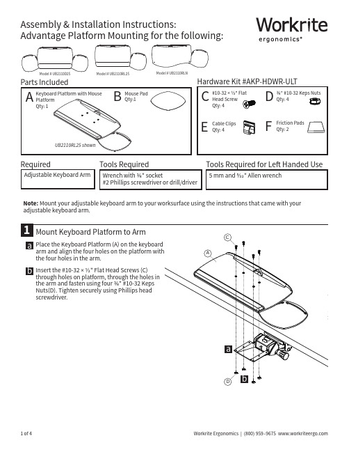
adjustable keyboard arm.Route Keyboard and Mouse Cords on Keyboard PlatformPlace keyboard cord underoverhang at either end of Optimizer. Place mouse cord under overhang closest to the mouse.Route the mouse cord into the slot at back rear corner of the Optimizer. Be sure to leave enough slack in cord to allow for unrestricted movement of the mouse.Place Mouse PadPeel the backing off the Mouse Pad (B) and place in either the left or right hand location. The Mouse Pad provides improved traction and pointing accuracy. It can be repositioned by simply peeling it up and placing it elsewhere.Apply Friction Pads or Hook & Loop SquaresPlace Friction Pads (F) on the bottom surface of your keyboard to keep it in place, if necessary. The Friction Pads will keep your keyboard from sliding when the platform is angled.Attach Cord Clips and Rout Cords on Arm & Under WorksurfaceNote: Make sure your keyboard arm is fully extended before routing your cables.Place one Cord Clip (D) on the side of the armmechanism. Place the other Cord Clip on the rear of the track. Do the opposite side in the same fashion if cords run down the left side.Caution: Adhesion is designed to bond immediately. You will not be able to reposition the clip once it's in place.3a abbOptimizerOverhang2B54EEFFUnder WorksurfaceArm fully extendedCables will be out of the way when platform is in useAdvantage Single Platforms are preconfigured for right handed use but can easily be converted to left handed use.Remove the Wrist Rest by pulling it off the Keyboard Platform. Remove the Mouse Platform using both a 5 mm and a 5/32" Allen Wrench. Set all subcomponents aside noting the placement.Remove the Mouse Traps from the Mouse Platform and flip the Mouse Pad over.a b。
科大语音酷4.0 硬盘安装版安装和使用方法
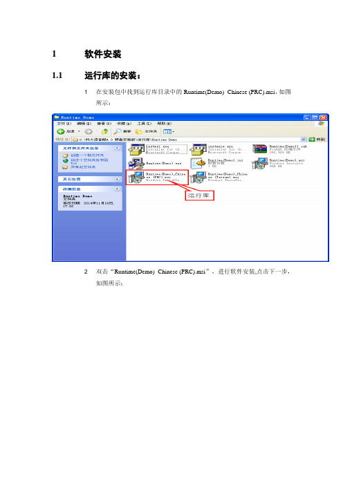
1软件安装1.1运行库的安装:1 在安装包中找到运行库目录中的Runtime(Demo)_Chinese (PRC).msi,如图所示:2 双击“Runtime(Demo)_Chinese (PRC).msi”,进行软件安装,点击下一步,如图所示:3 选择“我接受该许可证协议(A)”,点击下一步;4 进入了用户名和公司名的窗口,不用修改,一切默认,点击下一步;5 选择软件安装目录,建议默认路径,点击下一步;6 点击下一步;7 软件进入装界面;8 软件安装完成,如图所示1.2语音库的安装我们着重以安装小燕语音库(女声)为例来讲解语音库的安装步骤。
1 打开安装包找到小燕语音库中的安装文件“setup.exe”,如图所示:2 双击“”进行软件安装3 默认中文,点击“确定”;4 点击下一步;5 做好安装准备,点击“安装”开始安装软件;6 软件安装中;7 软件安装完成。
2软件的基本操作本章我将介绍软件的两大程序,合成演示程序和资源管理中心。
2.1合成演示程序的操作2.1.1软件功能介绍a 此程序主要有合成语音和文字语音转换两大功能,我们利用这两大功能不仅可以听书,还可以利用文字转语音文件这个功能,将得到的语音文件复制到mp3播放机里听读或刻录到cd碟片上放到碟机里播放。
b 这个合成演示程序每次只能听读64k等于叁万贰千七百六十八个汉字的文本和将64k的文本等于叁万贰千七百六十八个汉字导出为语音文件。
2.1.2软件操作1 在科大讯飞软件项目中,找到合成演示程序并打开,如图所示;2 在合成演示程序的主窗口里输入文字.3 选中输入的文字4 点击播放按钮试听5 导出语音6 选中编码格式和保存类型,输入文件名,然后保存。
2.1.3将普通wav文件转化为PCM 8KHz 8-bit 格式。
1 打开2 选择菜单文件--- 打开在弹出的对话框中选择刚刚保存的语音文件,然后打开。
3 选择菜单文件--- 另存为会弹出下面对话框4 点击更改按钮,然后选择下图中的格式和属性,然后点击确定。
Kwumsy K1 无线键盘用户指南说明书
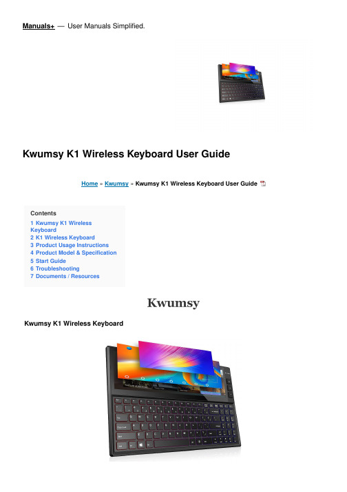
Manuals+— User Manuals Simplified.Kwumsy K1 Wireless Keyboard User GuideHome » Kwumsy » Kwumsy K1 Wireless Keyboard User GuideContents1 Kwumsy K1 WirelessKeyboard2 K1 Wireless Keyboard3 Product Usage Instructions4 Product Model & Specification5 Start Guide6 Troubleshooting7 Documents / ResourcesKwumsy K1 Wireless KeyboardON/OFF and Bluetooth connection indicator light: a it will be on for 3s after turning on the power switch, andCase status indicator light: the light will be on when the keyboard is in upper case state.Low-battery indicator light: it will flicker in case of low battery, promoting the user to make charging. Charging indicator light: it will be red while charging, and upon completion of the recharging, it will be green.Type-C USB charging interface OFF 6Power switchIn the menu of Bluetooth Setting, search K1 and it. click it, and then the keyboard will be connectedUpon successful Bluetooth connection, the paring indicator light will be off.Description of keyboard shortcut keys: Connect– Bluetooth pairing (press and hold Fn+C for 3 seconds) The above multimedia functions are realized by single press after switching the system.: this keyboard is three-system universal keyboard, and after confirming use of the device, press FN+QWIENotice1. When not in use for a long time, please turn off the keyboard, so as to lengthen the battery life.2. In order to ahieve longer battery life, it is recommended charging the keyboard only when the power lampflickers. The charging duration had better not be less than 2h each time.Energy-saving sleep modeWhen the keyboard makes no operation within 15min, it will enter Sleep Mode automatically. All LEDs will be off, and if to use again, you can press any key and wait for around 3s, then the keyboard will be awakened and will connect with the Bluetooth automatically, thus coming into normal operation.Troubleshooting1. Confirm that the power has been turned on2. Confirm that the keyboard is within operatable distance range.3. Confirm that the battery is of electricity.4. Confirm that Bluetooth Setting of tablet PC has been turned on.5. Confirm that wireless keyboard and Bluetooth have been connected.6. Confirm that wireless keyboard and Bluetooth have been paried.CleaningClean the keyboard with clear water, alcohol or similar alcohol agents.ChargingIn case of low battery, the low-battery indicator light will flicker constantly, and at this time the keyboard shall be charged.1. Conenct Micro end of the original accessory USB cable to Micro charging interface on the keyboard.2. Connect A end of USB cable to USB interface of the power adapter or computer (excluding power adapter).3. Charging indicator light: it will be red while charging, and upon completion of the recharging, it will be green.Documents / ResourcesKwumsy K1 Wireless Keyboard [pdf] User Guide2ATZ4-K1, 2ATZ4K1, K1, K1 Wireless Keyboard, Wireless Keyboard, KeyboardManuals+,。
凯kel Jeep JK V8 HEMIBuilder KIT 安装指南说明书

JK V8 HEMI® BUILDER KITOverviewInstallation Guide5.7L &6.1L HEMI2007 - 2008 JK - SWB, LWBCongratulations on purchasing your AEV HEMI JK Installation kit. These instructions have been written for shops or DIY individuals with experience in general mechanics and welding. AEV also assumes that this kit will be installed in a shop environment with access to general shop equipment. If you are not familiar with JK systems, please reference the Jeep Service Manual available at any Chrysler dealer.TIP 1:Although it is not required, AEV recommends using a two post hoist to remove the body from the vehicle. The Jeep JK Wrangler was designed by Chrysler to have the body and chassis built as two complete assemblies which are then mated together on the assembly line, because of this; removal of the body only requires about 45 minutes. The general procedure is outlined below:1. Discharge the AC system2. Disconnect the steering linkage3. Disconnect the appropriate brake lines at the ABS Module4. Disconnect the battery harness from the battery.5. Disconnect the engine ground located to the left of the battery.6. Unplug the 34 way powertrain connector at the fire wall (C100) and the 34 way Chassisconnector (C300) on the right hand side of the radiator.7. Unplug the PCM (C1, C2, C3, and C4).8. Disconnect the front left O2 sensor located below the master cylinder.9. Drain and disconnect the radiator and heater hoses.10. Disconnect the transmission cooler lines at the radiator.11. Remove the power steering reservoir from the body.12. Remove all the body mounts.13. Disconnect the emergency brake cables at the rear axle.14. Disconnect the transmission and transfer case cables15. Disconnect the fuel fill hose.16. Disconnect all vapor lines at the purge valve.17. Disconnect the top of the rear axle vent line.Once the body is separated, it is easy to remove the stock powertrain, weld in the new mounts and to install the assembled 5.7 or 6.1L powertrain and exhaust into the chassis. While the body is on the hoist, the completed cooling module, battery tray, air filter, and steering modifications can be completed. The body is then mated back to the chassis using the reverse procedure, the harnesses are plugged in, the brake lines are hooked back up and bled, the radiator hoses can then be connected and the vehicle can be filled with fluid and started.TIP 2:There are several variations of sensors, alternators, power steering pumps and air conditioning compressors used in different applications from 2005 onward. Please check that you have all the correct parts listed in the Bill of Materials provided. Pay particular attention to the AC pump, power steering pump and cam sensor.TIP 3:The exhaust system is designed to fit the 5.7L motor in a stock application. 6.1L motors can use the 5.7 exhaust but will be required to use the 5.7L Manifolds, Gaskets, and bolts also listed in the Bill of Materials. The routing has been fitted assuming a stock suspension and bumpers. The use of aftermarket suspensions, bumpers or other components may require modifications to the exhaust system or other components. Two Door Wranglers will need a section of straight exhaust pipe cut out of the system.TIP 4:Jeep Wranglers being converted from Manual to Automatic Transmissions will require AEV Part #31001027AA which is an additional wire for the body side of the harness. The other parts required to perform the manual to automatic conversion are listed in the Bill of Materials.TIP 5:Four door wranglers can use the stock driveshaft’s front and rear; two door models will need a new or modified rear driveshaft.TIP 6:WK and XK powertrains come with a rear sump aluminum oil pan. This pan will work but is easily damaged off-road. As an option, a steel pan is available from the Dodge Ram and all parts are listed in the supplied Bill of Materials. LX powertrains come with a front sump aluminum pan and will need to be changed to the steel pan. Be sure to reference a 5.7 manual regarding the “Torque To Yield” main bearing cap bolt.TIP 7:The stock JK transfer case cable bracket must have the corner clipped off in order to clear the floorpan as shown in the photo.FIG. 1The AEV Harness is the same for 5.7L and 6.1L conversions. There are two connectors included that are for the 5.7L engines only and must be tied up on 6.1L conversions. The MDS connector located at the top rear of block must be zip tied to the harness and will not be used for 6.1L. The EGR solenoid connector (black 6-way) located at the front right of engine has a plastic clip located in the connector which is designed to fasten under the air filter bracket on 6.1L conversions.TIP 8:5.7 conversions can utilize the Grand Cherokee or Commander engine cover however it must be modified prior to installation using the template provided on the last page of this document (FIG. 2).COMMENTS OR QUESTIONS? American Expedition VehiclesPhone: 406.251.2100Email:************************ Website: Remove thisJK V8 HEMI® BUILDER KITEngine & Transmission MountingInstallation Guide5.7,6.1 WK or XK Powertrains with Dodge 4WD Adapter in place07+ JK – SWB, LWB, LHD onlyINSTRUCTIONSA. MOUNTING PREPARATION1. After the 3.8L Powertrain is removed, disconnect the front ABS connectors at the frameand remove the right side wiring harness bolt on clips that are located on the framebehind the right side shock tower.2. Cut off the OE engine mounts from the frame and clean up the area with an 80 gritsanding disc.B. INSTALLATION OF THE ENGINE MOUNTS1. Each engine mount has an L or R inscribed into the metal indicating the Left from theRight. There is also an arrow indicating the front of the mount.2. If the mounts are coated, remove the coating in all areas to be welded.3. Place the mounts on the frame rail and line up the oval holes precisely. Tack in placeand finish weld as shown.4. Paint all bare areas as required5. Reinstall the wiring harness mount with the stock hardware.C. INSTALLATION OF THE TRANSMISSION MOUNT1. All 5-45 Transmissions must have the ¾ Ton or 1 Ton Dodge 4WD adapter (Mopar52119433AB) along with the seal (Mopar 52119498AA) installed prior to the transmission mount.2. Install the AEV Mount to the 4WD Adapter on the transmission using the stock bolts.3. Install the stock JK transmission Isolator to the AEV Transmission Mount using the two3/8x1” bolts, nuts and washers and two 1/2”x1” bolts, nuts and washers.D. INSTALLATION OF THE CROSS-MEMBER MOUNT1. Begin by bolting the top plate of the transmission cross member mount to the JKtransmission isolator using the stock hardware.2. Bolt the top plate of the transmission cross member mount to the JK cross member using4 of the 1/2-13 bolts, washers and flange nuts.3. Bolt the bottom plate of the transmission cross member mount to the bottom of the JKcross member using three of the stock bolts into the cross member nutserts. Drill out one hole using the bottom plate as a drill template. Use the remaining two 1/2-13 bolts,washers and flange nuts to secure the bottom plate to the cross member.4. Remove any paint from the top and bottom plates and weld as shown.5. Paint any raw material and welds.COMMENTS OR QUESTIONS? American Expedition VehiclesPhone: 406.251.2100Email:************************ Website: JK OPTIMA GROUP 31 Battery TrayInstallation Guide3.8, 5.7, 6.1 Powertrains07+ JK - SWB, LWB, LHD only Stock battery or Optima Group 31PREPARATIONA. REMOVE THE FACTORY BATTERY TRAY1. Remove the factory Air box, Purge Valve, and Battery.2. Release the TIPM (fuse block) from the battery tray; disconnect the large 34 way (black)connector as shown.3. Remove the tray from the vehicle.B. INSTALL THE NEW TRAY1. The new tray is a tight fit and there is only one way to install it without bending themounting tabs. Place the new tray starting with the three bolts on the rear of the tray; try to slide the tray into place in the front of the vehicle using a motion that is horizontal, from the center of the vehicle outward. Use the factory bolts to fasten the tray into position.2. Remove the TIPM bracket and the speed nuts from the original tray, re-use this hardwareon the AEV Tray and re-mount the TIPM and 34 way connector.3. Trim the studs on the firewall using a cut-off wheel.4. Install the battery as shown using the included bracket, J-bolt and nut.5. Mount the purge valve and rearrange the hoses as shown.C. 3.8L AIR BOX MOUNTING1. Mount the included brackets as shown to the front of the AEV Battery Tray. Install thebolts from inside the battery tray outward.2. Remove the stock rubber air box isolators from the original tray and reuse them in thesupplied brackets.3. Mount the stock air box.D. 5.7L & 6.1L AIR FILTER BRACKET1. Using the filter bracket supplied with the HEMI kit, mount the bracket to the front of thebattery tray and to the front of the vehicle as shown. Install the bolts from inside the battery tray outward.2. Mount the supplied K&N air filter to the bracket. (K&N #RC-4630)COMMENTS OR QUESTIONS? American Expedition VehiclesPhone: 406.251.2100Email:************************ Website: JK V8 HEMI® BUILDER KITPlumbingInstallation Guide5.7L,6.1L WK or XK Powertrains w/AC Pump (55111414AA)and Power Steering Pump (5290778AA)07+ JK – SWB or LWB, LHD onlyA. AEV HEMI FUEL LINE1. Remove the locking clip out of the plastic fuel line at the tank as shown.2. Install the stud provided into the 5-45 transmission and reuse the steel fuel line bracketfrom the 3.8L engine.3. Install the AEV Fuel Line; be sure to lubricate all tubes or hoses prior to installation inorder to avoid damaging seals.B. POWER STEERING LINES1. This step is to be performed after the powertrain has been installed.2. Be sure you are using the correct power steering pump (Mopar #5290778AA)3. Install the lines as shown.4. Be sure to lubricate all O-rings prior to assembly.C. AEV AC LINES (BODY SIDE)1. Install the liquid line (Condenser to Firewall). Use the stock hardware to connect thelines.2. Fasten the line to the ground stud located on the left fender structure immediately behindthe ABS module using the supplied clip.3. Be sure to lubricate all O-rings prior to assembly.D. AEV AC LINES (POWERTRAIN SIDE)1. Be sure the correct AC compressor is being used (Mopar #55111414AA)2. Install the suction line (Compressor to Firewall) onto the compressor using stockhardware. The firewall side will be installed when the body is mated to the chassis.3. Install the AC Discharge line (Compressor to Condenser) to the compressor using thestock hardware. Install the stock pressure transducer. The condenser side will beinstalled when the body is mated to the chassis.4. Be sure to lubricate all O-rings prior to assembly.E. AEV TRANSMISSION COOLER1. Install the transmission cooler to the AC condenser as shown. Locate the cooler 3.5”from the top of the condenser and 3.5” from the right side of the condenser. Pre-install transmission cooler hose on each barb of the transmission cooler.2. Using the Mopar 55038175AA Transmission Cooler lines remove the OE hose portion asshown. Connect the Transmission Cooler lines to the transmission Cooler once the body is mated to the chassis.F. HEATER HOSES1. Cut the stock 3.8L hoses as shown and fit to the completed powertrain before mating thebody to the chassis.G. EVAPORATIVE PURGE VALVE HOSES1. Reuse the stock 3.8L hose from the fuel tank to the purge valve. Attach this line to thefuel line using the stock bracket and a couple zip ties.2. Use Mopar part #4578627AA hose to go from the intake, around the engine to the purgevalve. This hose doesn’t quite go all the way to the purge valve; you will need to use a portion of the stock 3.8L purge valve line from the purge valve to the engine.H. RADIATOR HOSES1. Install the upper and lower radiator hoses as shown.2. Trim the corner off of the fan shroud in order to clear the lower radiator hose.COMMENTS OR QUESTIONS? American Expedition VehiclesPhone: 406.251.2100Email:************************ Website: JK V8 HEMI® BUILDER KITExhaustInstallation Guide5.7L,6.1L WK or XK Powertrains w/Grand Cherokee or Commander Manifolds07+ JK - SWB, LWBAEV’s HEMI exhaust is designed specifically for the 5.7L HEMI but can be used on the 6.1L engine if the 5.7L manifolds, gaskets and bolts are used. The exhaust is designed around the stock suspension and bumpers and may need to be modified to accommodate aftermarket suspensions, bumpers or other accessories.DO NOT TIGHTEN ANY PART OF THE EXHAUST SYSTEM UNTIL THE FINAL DESIRED FIT IS ACHIEVED!1. Install the tailpipe section and isolator.2. Install the muffler section.3. Install the downpipes and catalytic converters.4. Install the hanger mount into the existing cross member hole behind the muffler.5. Adjust for clearances paying particular attention to the area around the front driveshaft,JK cross member, transmission pan, rear track bar and rear bumper. Once everything is adjusted properly, the clamps can all be tightened.6. The right hand down tube that goes under the transmission oil pan should be parallel withthe JK cross member when fitted properly.7. You may wish to tack weld all joints for increased durability.8. Install the star washers on the three isolator hangers.Note: 2DR Shown, 4DR SimilarNote: 2DR Shown, 4DR SimilarCOMMENTS OR QUESTIONS? American Expedition VehiclesPhone: 406.251.2100Email:************************ Website: AEV SRA INTAKE FOR 5.7L AND 6.4L ENGINESPN: AEV30206AA1. This intake must be used in conjunction with an AEV PCM that has beenprogrammed to take full advantage of the long and short runners.2. Use the 6.4L throttle body only.3. Do not use the throttle body screws that come with the 6.4L engine. Onlyuse the throttle body screws supplied with your AEV intake. FAILURE TO USE THE CORRECT SCREWS WILL BREAK THE INTAKE MANIFOLD AND VOID YOUR AEV WARRENTY.4. There are 10 seals on the bottom of the manifold, one between theintake manifold actuator and intake, and one between the throttle body and the intake. Be sure all seals are installed.5. The intake tube from the air fi lter to the throttle body must be trimmedas shown below. (Remove grey portion) IMPORTANT: IF INSTALLING A5.7L ENGINE, ONLY TRIM INTAKE TUBE IF USING THE6.4L INTAKE.。
科视Christie 4K-RGB CP4325-RGB、CP4330-RGB 安装与设置指南说明书

安裝與設定指南020-102853-03 Cinema 4K-RGB CP4325-RGB、CP4330-RGB注意版權與商標Copyright © 2019 Christie Digital Systems USA Inc. 保留一切權利。
所有品牌名稱與產品名稱分別屬於各擁有者的商標、註冊商標或商品名稱。
常見問題我們已盡最大努力確保準確性,但是有些情況下,產品或可用性變更可能未能及時在本文件中反映。
科視保留不經通知逕行變更規格的權利。
效能規格是代表性規格,但是可能隨Christie 無法控制的條件而異,例如,產品在正常工作條件下的維護。
效能規格是以本文件印刷時可用的資訊為依據。
Christie 對於此資料不提供任何保證,包含 (但不限於) 針對特定用途所隱含的適用保證。
Christie 對於此資料內含的錯誤不負任何責任,對於此資料的履行或使用而產生的意外或間接損害亦不負任何責任。
加拿大和中國的製造場所通過 ISO 9001 認證。
加拿大的製造場所也已通過 ISO 14001 認證。
保固產品受到 Christie 標準有限保固,相關的詳細資訊請聯絡 Christie 經銷商或 Christie。
除了 Christie 標準有限保固中可能規定的限制和與您的產品相關或適用於您產品的限制之外,本保固不包括:a.任一方向運送過程中造成的問題或損壞。
b.本產品與非 Christie 設備組合 (例如分配系統、攝影機、DVD 播放器等) 或本產品與任何非 Christie 介面裝置一起使用所造成的問題或損壞。
c.誤用、電源錯誤、意外、火災、水災、閃電、地震或其他天然災害造成的問題或損壞。
d.安裝/校準不當、由 Christie 服務人員或 Christie 授權服務提供者以外人員修改設備所造成的問題或損壞。
e.戶外應用期間,為保護環境而使用的第三方產品外殼必須經由 Christie 核可。
f.在行動平台或其他可移動裝置上使用本產品,且未經 Christie 設計、修改或認可此類產品可用於此目的時所造成的問題或損壞。
科格尼克7000系列视觉系统安装说明书

Cognex in-sight® 7000 series vision system installation manual. Cognex insight 8000 price. Cognex insight 7000 price. cajeyekikipifo
Access the main content of -hsll Dmlt-HPI-W DMLT-HPIT-WHI-WHI-W DMLA-HPI-PLOCOV (Unique -C16F08- HSLL-HPIT-W DMLT-HPIT-WHI-WLA-HPP-PPCOV ( C24F06 -HSL DMLT-HPIT-HPIT-HPIT-WHI-SLA-HP-HP-PCOV (RED) DMPT-HPT-PLO-F DMLA-HLA-HPOV DMLA-HLA-HLCOCOV DMLA DMLA -HPot-DFCOV 35 mm only HSLL HSLL DMLNC35F08-HSLL-HPT-HP-RMLT-HPIT-WHI-DHI-HPI-PLTO (Red only) DMLA-HPIt-Fcov-F DMLA-HPI-APVOV DMLA-HPI-DLCOV in the VIDI-Sight is class is On the basis of our class vision suite in sight to help you use the skills of our in -depth learning technology of Vidi, using an intuitive interface in the vision suite for a rapid adjustment and an initial apprenti
蒂 niet Kwik Top Kit II 安装指南说明书
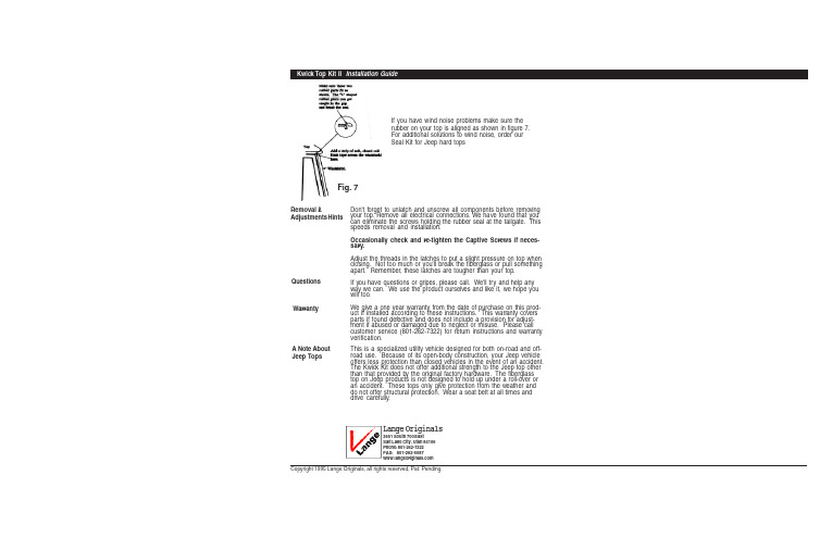
Copyright 1995 Lange Originals, all rights reserved, Pat. Pending.If you have wind noise problems make sure the rubber on your top is aligned as shown in figure 7.For additional solutions to wind noise, order our Seal Kit for Jeep hard topsRemoval &Adjustments HintsDon't forget to unlatch and unscrew all components before removing your top. Remove all electrical connections. We have found that you can eliminate the screws holding the rubber seal at the tailgate. This speeds removal and installation.Occasionally check and re-tighten the Captive Screws if neces-sary.Adjust the threads in the latches to put a slight pressure on top when closing. Not too much or you'll break the fiberglass or pull something apart. Remember, these latches are tougher than your top.If you have questions or gripes, please call. We'll try and help any way we can. We use the product ourselves and like it, we hope you will too.We give a one year warranty from the date of purchase on this prod-uct if installed according to these instructions. This warranty covers parts if found defective and does not include a provision for adjust-ment if abused or damaged due to neglect or misuse. Please call customer service (801-262-7322) for return instructions and warranty verification.This is a specialized utility vehicle designed for both on-road and off-road use. Because of its open-body construction, your Jeep vehicle offers less protection than closed vehicles in the event of an accident.The Kwick Kit does not offer additional strength to the Jeep top other than that provided by the original factory hardware. The fiberglass top on Jeep products is not designed to hold up under a roll-over or an accident. These tops only give protection from the weather and do not offer structural protection. Wear a seat belt at all times and drive carefully.Lange Originals3651 South 700 EastSalt Lake City, Utah 84106Phone: 801-262-7322FAX: 801-262-5087Fig. 7QuestionsWarrantyA Note AboutJeep Tops*Jeep is a registered trademark of Chrysler Corp.Kwick Top Kit IIITMInstallation GuideN ewa n d I m p r o v e d If you have a problem with missingparts or need help, do not call yourdealer, call Lange directly801-262-7322for prompt attention.Copyright 1995 Lange Originals, all rights reserved, Pat. Pending.The Kwick T op Kit III is designed to help you remove your Jeep hard top quickly and easily. The premium hardware supplied in this kit replaces the standard Jeep* fasteners. The K wick K it lets you remove your top just using your hands, no tools. Special patented draw latches adjust and secure your top to the windshield. These heavy duty latches will draw your top down tighter and will help eliminate wind noise. The eight screws located around the back of the top remove with just one-and-one-quarter turn. Your Kwick Kit II should install in about one hour and requires some drilling.IntroductionParts Included2. Use the larger rivets and rivetthese parts to windshield frame and top. Keep the parts tight against the windshield or top as you rivet so there is no play when the rivets are compressed.Electric drill with bits, hand pop riveter with a long snout (obtained at any hardware store for about $12), center punch and pencil.Tools Required Read through these instructions carefully before starting!Make sure your top is installed correctly and all fasteners tightened before starting. Make sure the rubber molding around the windscreen pillar is aligned properly (see figure 7).1. Install the draw latches at the windshield locations shown infigure 2. Center each latch behind the sun visor. Use figure3 to locate and mark the position of the keepers andLatches. Locating these parts accurately is impor-tant. If the Keeper and Latch are too close,there will not be enough thread in theadjustment to keep the Latch closedtightly. Mark, center punch, anddrill holes for these e a 3/16" drill bit.Note: Mount the latch on the top and the Keeper on the windshield. After mounting the latches and keepers, ad-just the threaded rod so that when the latch closes it com-presses the top slightly when closed--not too tight. Tighten the lock nut to retain the setting.Installation StepsFig. 2*Jeep is a registered trademark of Chrysler Corp.4. Remove the top carefully and place in a safe location. Note: Removing the top re-quires two people capable of lifting at least 100 pounds each. Locate the original eight mounting holes on the Jeep body. Mark, drill (1/8"), and rivet (use the smaller aluminum rivets here) a captive screw receptacle as shown in figures 4 & 5 at each hole site. Make sure to align and mount as shown.Now reinstall the hard top. Align the rubber around the windshield as shown in figure 7 for a better seal before closing the draw latches. Now attach the captive screws and flat washers as shown in figure 6.Screw in the captive screws until tight. Check for fit and tightness. Do not over tighten! Finger tight only.Read through these instructions carefully before starting!Make sure your top is installed correctly and all fasteners tightened before starting. Make sure the rubber molding around the windscreen pillar is aligned properly (see figure 7).1. Install the draw latches at the windshield locations shown infigure 2.Center each latch behind the sun visor. Use figure3 to locate and mark the position of the keepers andLatches. Locating these parts accurately is impor-tant. If the Keeper and Latch are too close, there will not be enough thread in theadjustment to keep the Latch closedtightly. Mark, center punch, anddrill holes for these parts.Use a 3/16" drill bit.Note: Mount the latch on thetop and the Keeper on thewindshield. After mountingthe latches and keepers, ad-just the threaded rod so thatwhen the latch closes it com-presses the top slightly whenclosed--not too tight. Tighten thelock nut to retain the setting.Mark , drill & rivet on the inside of thewindshield frameas shown. Positionthe Keeper on the lower side of theframe with the lower edge of theKeeper just above the radius of thewindshield frame.GlassAluminum StripAcross theFront of theTopKeeperMark, drill & rivet the Latch exactlyas shown. The bottom edge ofthe Latch should line up with thealuminum strip on the lowermiddle break.Hole &RivetThe Latch mounts tothe front of the top asshown.FiberglassTopUpper Windshield Frame(cross section)Hole &Rivet3. Remove the sheet metal screws attachingthe top to the windshield. Discard. Make surethe new draw latches you have just installedstay in the released position. Unhook theelectrical connections and hoses at the body(if any).Fig. 6Fig. 3Fig. 5Fig. 4。
Kessler Kwik Release 安装说明说明书
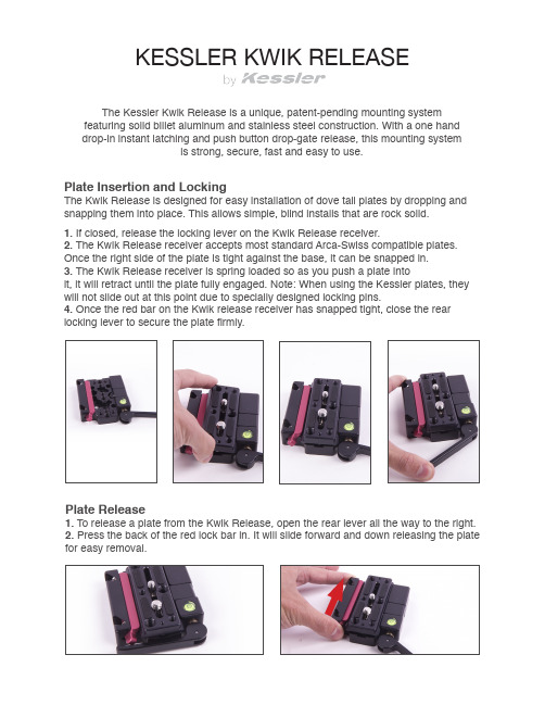
KESSLER KWIK RELEASEThe Kessler Kwik Release is a unique, patent-pending mounting system featuring solid billet aluminum and stainless steel construction. With a one hand drop-in instant latching and push button drop-gate release, this mounting systemis strong, secure, fast and easy to use.Plate Insertion and LockingThe Kwik Release is designed for easy installation of dove tail plates by dropping and snapping them into place. This allows simple, blind installs that are rock solid.1. If closed, release the locking lever on the Kwik Release receiver.2. The Kwik Release receiver accepts most standard Arca-Swiss compatible plates. Once the right side of the plate is tight against the base, it can be snapped in.3. The Kwik Release receiver is spring loaded so as you push a plate intoit, it will retract until the plate fully engaged. Note: When using the Kessler plates, they will not slide out at this point due to specially designed locking pins.4. Once the red bar on the Kwik release receiver has snapped tight, close the rear locking lever to secure the plate firmly.Plate Release1. To release a plate from the Kwik Release, open the rear lever all the way to the right.2. Press the back of the red lock bar in. It will slide forward and down releasing the plate for easy removal.Kessler Plate InstallationWe recommend using Kessler Kwik Release plates with the Kwik Release system because they hold tight dimensional tolerances for the best compatibility and function. We offer six types:Short Camera Plate & Long Camera PlateScrew the (2) 1/4”-20 camera screws or (1) 1/4”-20 and (1) 3/8”-16 camera screws into the appropriate holes on the camera or rig.Utility Plate & Slider PlateUse the included tool kit to mount the plate to the bottom of accessories like the 100mm High Hat, CineDrive Pan & Tilt Head, Pocket Dolly 3, etc.Mini PlateScrew the 1/4”-20 camera screw into the appropriate hole on the camera or use the (2) 1/4-20x3/8” Socket Head Cap Screw to attach the plate to the bottom of the Pocket Jib Traveler.K-PlateScrew the 1/4”-20 and 3/8”-16 camera screw into the appropraite holes on the camera or rig.Short Camera Plate Long Camera Plate Utility PlateSlider Plate K-PlateMini PlateKwik Release with CineSlider1. Locate the 9/64” allen key and two #8-32 x 1/2” Socket Head Cap Screws in the Kwik Release Tool Kit2. Line up the Kwik Release receiver with the holes on the cart as shown below.3. Screw the two #8-32 x 1/2” screws through the receiver and into the cart as shownKwik Release with Pocket Dolly 31. Locate the 5/32” allen key and two 1/4”-20 x 1/2” Countersunk Screws in the Kwik Release Tool Kit2. Line up the Kwik Release receiver with the holes on the cart as shown below.3. Screw the two 1/4”-20 screws through the receiver and into the cart as shown below.Kwik Release with Pocket Dolly v2.0 and Stealth1. Locate the 9/64” allen key and two #8-32 x 1/2” Socket Head Cap Screws in the Kwik Release Tool Kit2. Line up the Kwik Release receiver with the holes on the cart as shown below.3. Screw the two #8-32 x 1/2” screws through the receiver and into the cart as shownKwik Release with Hercules 2.0 Head1. Locate the 5/32” allen key and two 1/4”-20 x 1/2” Countersunk Screws in the Kwik Release Tool Kit2. Line up the Kwik Release receiver with the holes on the head as shown below.3. Screw the two 1/4”-20 x 1/2” screws through the receiver and into the head as shown.Kwik Release with Low Profile Ball Head v2 (1/4”-20 or 3/8”-16)1a. The easiest way to mount the Kwik Release to the Low Profile Ball Head is to attach1b. For a more permanent mounting solution, remove the top plate of the Low Profile Ball Head (1/4”-20 or 3/8”-16) and use the three #8-32 x 1/2” screws to affix the Kwik Release directly to the ball head with the corresponding mount holes.。
JKS Quicker Disconnect 安装说明书
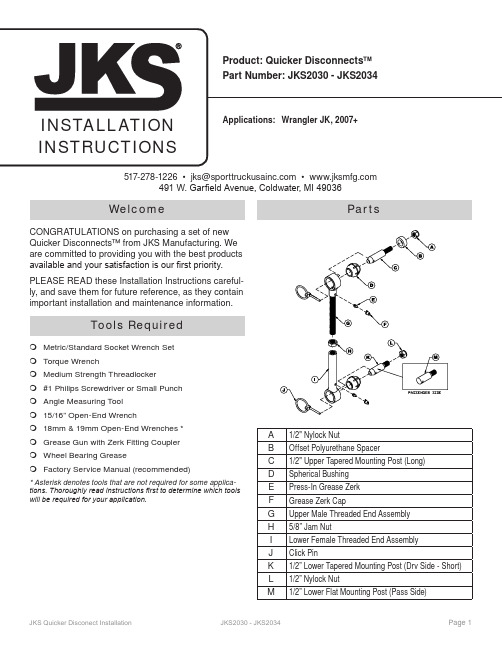
WelcomeCONGRATULATIONS on purchasing a set of new Quicker Disconnects™ from JKS Manufacturing. We are committed to providing you with the best products available and your satisfaction is our first priority. PLEASE READ these Installation Instructions careful-ly, and save them for future reference, as they contain important installation and maintenance information.Tools RequiredMetric/Standard Socket Wrench SetTorque WrenchMedium Strength Threadlocker#1 Philips Screwdriver or Small PunchAngle Measuring Tool15/16” Open-End Wrench18mm & 19mm Open-End Wrenches *Grease Gun with Zerk Fitting CouplerWheel Bearing GreaseFactory Service Manual (recommended)* Asterisk denotes tools that are not required for some applica-tions. Thoroughly read instructions first to determine which tools will be required for your application.PartsA1/2" Nylock NutB Offset Polyurethane SpacerC1/2" Upper Tapered Mounting Post (Long)D Spherical BushingE Press-In Grease ZerkF Grease Zerk CapG Upper Male Threaded End AssemblyH5/8” Jam NutI Lower Female Threaded End AssemblyJ Click PinK1/2” Lower Tapered Mounting Post (Drv Side - Short) L1/2” Nylock NutM1/2” Lower Flat Mounting Post (Pass Side)517-278-1226•************************• 491 W. Garfield Avenue, Coldwater, MI 49036Higher Rollover RiskModifying your Jeep® to improve off-road perfor-mance may result in vehicle handling different than as factory equipped, including increased ride-height and/or chassis articulation; reduced lateral stability and higher risk of roll-over or other accident. Also, owner’s choice of larger tire and wheel combinations may require additional braking force or increased stopping distances.To reduce risk of serious injury and accident:ÂChoose modifications that balance your actualhighway & off-road use. ÂAvoid sharp turns, abrupt maneuvers or steepside-cambers. ÂAvoid other maneuvering conditions which maycause the vehicle to trip, roll, lose traction or com-promise your ability to safely brake in an emer-gency. ÂRoutinely inspect your vehicle components for un-usual wear or off-road damage. Repair or Replace any unserviceable components before use. ÂDo not modify or combine body lifts with other me-chanical lifts contrary to manufacturers’ or Jeep® recommendations & warnings. ÂAcquaint any other drivers with your vehicle modi-fications and handling. ÂAlways wear seat belts and/or appropriate off-roadrestraints, reduce your speed, Tread Lightly©.ImportantNOT COMPATIBLE WITHaftermarket swaybars. Install product with Original Equipment swaybar only.SOME VEHICLES MAY REQUIRE extended front brake hoses or other modifications to compensate for additional suspension travel.NEVER DISCONNECT swaybar when operating vehicle on public roads.WHEN DISCONNECTED , the Quicker Disconnects must be completely removed from vehicle, and the swaybar must be secured to the chassis in the hori -zontal position to prevent interference with tires.Stay Connected On-RoadOn-highway safety is enhanced by controlling body roll. Never disconnect swaybar when operating on public roads.To assure intended performance JKS® Quicker Dis-connects™ are NOT COMPATIBLE with aftermarket Swaybars. Install ONLY with Jeep® factory sway bar. On-highway safety is enhanced by controlling body roll. Never disconnect swaybar when operating on public roads. When disconnected off-road, swaybarmust be secured to prevent interference with other suspension components.Brakelines must be secured and retain some slack throughout range of suspension travel. Check after installation of Quicker Disconnects™ & use longer DOT approved brakelines if necessary.Installation1. REMOVE ORIGINAL EQUIPMEN (OE)SWAYBAR LINKSRemove front swaybar drop links and mountinghardware per the factory service manual instruc-tions for your vehicle.2. INSTALL UPPER MOUNTING POSTSLocate the long stainless steel 1/2" Upper TaperedMounting Posts (C) with attached Offset Polyure-thane Spacers (B). Remove the nut and mount the Upper TaperedMounting Posts (C) on outboard side of the sway-bar, ensuring small Click Pin holes are horizontalor parallel with the ground.Apply medium strength threadlocker to the tip ofmounting post threads.Secure mounting posts to swaybar by installing1/2" Nylock Nuts (A) from the inboard side andtighten to 65 ft-lb. using a torque wrench.HINT: A small Philips head screwdriver or punch inserted into the Click Pin hole will enable you to pre -vent the mounting post from rotating when tightening the nut.3. INSTALL LOWER MOUNTING POSTSRemove the nut and insert stainless steel 1/2”Lower Tapered Mounting Posts (K & M) into lowerswaybar link holes on front axle. Position postswith tapered ends pointing inboard, ensuring smallClick Pin holes are horizontal or parallel with theground.IMPORTANT: The passenger side lower post is squared off to provide sufficient clearance between the post and the OE trackbar bracket on the axle.Apply medium strength threadlocker to the tip ofmounting post threads.Install 1/2” Nylock Nuts (L) on outboard side of lower swaybar link brackets and tighten to 65 ft-lb.using a torque wrench.Note: In some cases a rotary grinder may be neces-sary to slightly open up the sway bar hole to clear the 1/2" bolt. This ensures a tight fit.4. SET QUICKER DISCONNECTLENGTHSDetermine the Ideal Swaybar Angle for your ve-hicle according to the following chart.Max. length is based on required thread & jam nut engage-ment. Measure & DO NOT extend Quicker Disconnects™ beyond maximum length of your part number (bushingscenter to center).IMPORTANT: Bushing cradles at both ends of Quicker Disconnect must remain parallel with each other when Jam Nut is tightened.5. INSTALL QUICKER DISCONNECTSSlide Upper Ends (G) and Lower Ends (I) ofQuicker Disconnects onto the Tapered Mounting Posts (C, K & M).Insert Click Pins (J) as illustrated to secure.When properly installed, the ring on the Click Pin will “snap” against the shaft of pin. When installed back-wards, the ring does not fit snugly against shaft.When properly installed, the ring on the Click Pin will“snap” against the shaft of pin. When installed backwards,the ring does not fit snugly against shaft.6. LUBRICATE QUICKER DISCONNECTSLubricate all Grease Zerk fittings on the QuickerDisconnects immediately after installation usingcommon wheel bearing grease or equivalent.7. CORRECT OPERATION OF QUICKERDISCONNECTSRemove the Click Pins (J) from the Upper andLower Tapered Mounting Posts (C, K & M). Completely remove Quicker Disconnects fromvehicle and store safely inside vehicle. HINT: To avoid losing Click Pins, reinstall them on mounting posts while Quicker Disconnects are removed. Using JKS lanyards (JKS2039), plastic wire ties,bungee cord or equivalent, secure the swaybar to the chassis in the horizontal position.IMPORTANT: When disconnected, the swaybar must be secured in the horizontal position to pre-vent interference with the tires. Failure to secure the swaybar correctly can lead to severe tire dam-age.To reconnect, remove Click Pins (J) from mountingposts and rotate swaybar down. Slide Quicker Disconnects back onto mountingposts and reinstall Click Pins. HINT: Install pas -senger side Quicker Disconnect first for easiestreinstallation.TroubleshootingIf swaybar does not rotate freely, remove from vehicle, clean and apply rubber lubricant to chassis-mounted bushings, and reinstall.MaintenanceIt is important to lubricate Quicker Disconnects fre-quently for the first three (3) months after installation to evacuate contaminants that may build up during break-in period.After break-in period, Quicker Disconnects should be lubricated regularly as part of vehicle maintenance schedule.Regular cleaning with pressurized water is recom-mended to maximize ease of operation and reliability. Always lubricate afterwards to evacuate any moisture.©2017 JKS Manufacturing, Inc & Aftermarketing, LLC Revision Date 07/28/17。
Carlin Combustion Technology Burner Cover Kit 安装说明
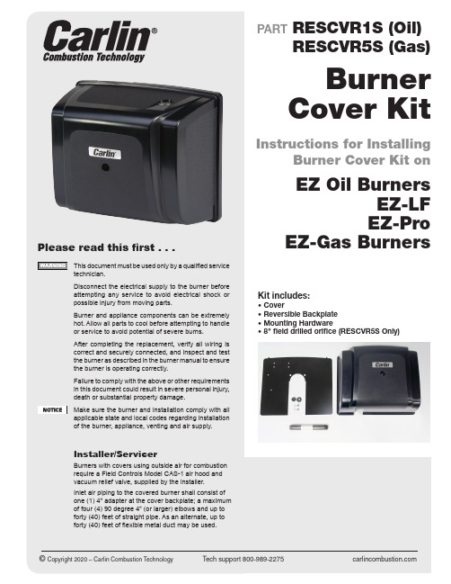
Tech support 800-989-2275 2Step 1Turn off the power to the burner and appliance. Shut off the service switch and pull the fuse or disable the breaker to prevent accidental power restoration.Step 2 Remove electrical wiring from burner J-box.Step 3Mounting the backplate: The backplate is re-versable to accommodate the air inlet to enter the burner on the left side (vertical or horizon-tal) or right side (vertical only).Mount backplate in the desired orientation and secure to the burner using the two 5/16-18 x 5/8”bolts provided (as shown)Step 4Remove 7/8" knockout in upper right or left corner of backplate and install the rubber grom-met provided in the kit. Route the power wires through the rubber grommet and reconnect themto burner.Step 5Drop the cover on the tabs of backplate and secure with mounting screw.Step 6Restore power to the unit and test operation. Combustion test must be performed with new cover installed and secured to burner.Installation Instructions for RESCVR1S (oil)3Step 1Turn off the power to the burner and appliance. Shut off the service switch and pull the fuse or disable the breaker to prevent accidental power restoration. Turn off the gas supply to the burner.Step 4Looking at the backplate remove one 7/8" knock-out – either lower left or lower right. This is for the new gas valve harness. Mount the backplate to the burner chassis using the two 5/16-18 x 5/8" bolts and star washers provided.Remove knockoutStep 6Install the plastic grommet provided in the kit into the airflow switch and route the harness wires through the grommet and attach to air-flow switch.Step 7Remove 7/8" knockout in upper right or left corner of backplate and install the rubber grommet provided in the kit. Route the power wires through the rubber grommet and recon-nect them to burner.Installation Instructions for RESCVR5S (gas)Step 2Remove wiring harness connecting valve andpressure switch.Step 3Remove the gas valve and the 4" x 3/4" orifice nipple from the burner. Check orifice size and compare it to the new 8" x 3/4" orifice. Drill the new orifice to the same size as the old one. Re-install the gas valve and new 8" x 3/4" orifice intothe burner.Step 5Mount the new gas valve wiring harness to the gas valve cover and connect the spade termi-nals to the gas valve, then mount the harnessto the backplate.Continued on next page4Air Changes with TemperatureStep 8Drop cover on tabs of backplate and securewith mounting screw.Step 8Start burner and check operation.Combustion test must be performed withnew cover installed.Burners with ducted combustion air –MEASURE incoming combustion air temperature and set the CO 2 (or O 2) using the following chart:Installation Instructions for RESCVR5S (continued)Combustion Air TemperatureOnce a burner is setup, the fan always pulls through about the same volume of air (cfm) regardless of air tem-perature. (Air flow will be reduced if the overfire pressure increases due to a dirty heat exchanger, or if the inlet air is blocked or the blower blades are dirty or linted.)Air density changes with temperature. The colder the air, the more dense the air. The blower pulls in a constant volume of air. If the air density changes, weight of air (pounds) entering the burner changes. When the air is colder (heavier), more pounds of air enter. When the air is warmer (lighter), less pounds of air enter.When combustion air comes from inside, it comes in at room temperature, so the temperature of the air doesn’t change much throughout the year. But when air is ducted directly from outside, it isn’t heated much before it reaches the burner. It comes in pretty close to the outside temperature. The air temperature difference between summer and winter could be 100 degrees in some areas.The table to the right shows the change in the amount of air (cubic feet) required as the temperature of the air changes.Take the air temperature into account when you set up a burner with ducted combustion air.% CO 2 rises as air temperature rises.% CO 2 drops as air temperature drops.If you don’t consider this, burner combustion can be-come very poor as air temperature changes.Refer to the setup temperature chart to the right for sug-gested setup values based on entering air temperature.MNCVR2 030620550433KIT outside air kit for use with RESCVR1S and RESCVR5S 50433KIT includes:• 4" air intake• Backplate filler plate with bolts and washers • Rubber filler piece for cover• 2 plastic plugs for unused holes in backplate • Rubber Grommet • 2 7/8" Hole PlugsStep 1Remove one of the two air inlet knockouts, then install the air inlet to backplate with screws pro-vided.Step 2Fill unused 1/4" holes with plastic plugs provided.Step 3Install backplate filler using the two 5/16-18 x 5/8" bolts and star washers provided. Heads ofplastic rivets contact both sides of backplate.Step 6Install rubber cover filler piece.Step 7Secure cover to backplate and install the 4" outside air intake system (not supplied by Carlin Combustion). Follow installation instructions from the manufacturer of air intake system.Step 8Put unit back into service, restore electrical power back to appliance, turn on fuel supply.Step 9Combustion test must be performed with cover secured to burner. Set up burner using the combustion air temperature chart in thismanual.Step 4Remove one of the three large round holes to run the power cable through. After the cable is run, install the split grommet around the cable.Step 5Plug any unused 7/8" holes with plugs providedin kit.。
杰克逊第2安装说明书

杰克逊第2安装说明书
1、GX-Works2是三菱电机新一代PLC软件,具有简单工程(Simple Project)和结构化工程(Structured Project)两种编程方式。
2、支持梯形图、指令表、SFC、ST及结构化梯形图等编程语言。
3、可实现程序编辑,参数设定,网络设定,程序监控、调试及在线更改,智能功能模块设置等功能。
4、适用于Q、QnU、L、FX等系列可编程控制器。
5、兼容GX Developer软件。
6、支持三菱电机工控产品iQ Platform综合管理软件iQ
7、具有系统标签功能,可实现PLC数据与HMI、运动控制器的数据共享
安装:
1.双击运行setup.exe
2.选择确定,并点击下一步
3.输入信息
①姓名、公司名随便写
②产品ID在文件夹的序列号.txt 中,随便选一个就好
04选择安装路径
05确认信息,等待安装过程
06安装使用说明书
点击“是”
07完成安装
√
测试:
1.新建工程
选择系列、类型
双击编写一个简单的梯形图程序
02转换
03模拟运行
POWER、RUN显示灯绿色,软件程序正常运行
点击模拟停止,窗口关闭
PS.模拟停止后程序不能编辑,可能是因为打开了读取模式,改成写入模式即可。
科箭操作手册

科箭操作手册(最新版)目录1.科箭操作手册概述2.科箭操作手册的内容3.科箭操作手册的使用方法4.科箭操作手册的优点5.科箭操作手册的适用对象正文【科箭操作手册概述】科箭操作手册是一款全面介绍科箭软件操作流程的实用指南,旨在帮助用户更轻松、更高效地掌握和应用科箭软件。
该手册内容详尽,覆盖了科箭软件的各个功能模块,包括安装、配置、操作、维护等方面的知识,是科箭软件使用者不可或缺的参考工具。
【科箭操作手册的内容】科箭操作手册共分为以下几个部分:1.前言:简要介绍科箭软件的背景、功能和适用场景,以及本手册的目的和使用方法。
2.安装与配置:详细介绍科箭软件的安装流程和注意事项,以及系统配置的相关知识。
3.功能模块:分别介绍科箭软件的各个功能模块,包括但不限于数据管理、报表生成、权限控制等,每个模块都配有详细的操作步骤和示意图。
4.常见问题与解决方案:针对用户在使用过程中可能遇到的问题,提供相应的解决方法和技巧。
5.维护与升级:说明科箭软件的维护方法和升级流程,以及需要注意的相关事项。
【科箭操作手册的使用方法】为了更好地使用科箭操作手册,建议用户按照以下步骤进行:1.首先,通读前言部分,了解科箭软件的概况和使用手册的目的。
2.在安装和配置科箭软件时,参考相应章节,确保安装和配置的正确性。
3.在日常使用过程中,根据需要查阅功能模块部分,学习并掌握各个功能模块的操作方法。
4.如遇到问题,查阅常见问题与解决方案部分,寻找相应的解决方法。
5.对于维护和升级需求,参考维护与升级部分,按照指导进行操作。
【科箭操作手册的优点】科箭操作手册具有以下几个优点:1.内容全面:涵盖了科箭软件的各个方面,从安装、配置到操作、维护,为用户提供了全方位的指导。
2.结构清晰:按照逻辑顺序编排章节,便于用户快速定位和查阅相关内容。
3.实例丰富:手册中配有大量操作示意图和实例,帮助用户更直观地理解和掌握操作方法。
4.实用性强:针对实际使用过程中可能遇到的问题,提供详细的解决方案和技巧,具有很高的实用价值。
- 1、下载文档前请自行甄别文档内容的完整性,平台不提供额外的编辑、内容补充、找答案等附加服务。
- 2、"仅部分预览"的文档,不可在线预览部分如存在完整性等问题,可反馈申请退款(可完整预览的文档不适用该条件!)。
- 3、如文档侵犯您的权益,请联系客服反馈,我们会尽快为您处理(人工客服工作时间:9:00-18:30)。
Install –
1) Install main program.
1)Install FEKO Suite 6.0 per following option, and done.
2) Modify Original program.
1)Backup your original \FEKO\License\secfeko.dat (if any) and
\FEKO\bin\secfeko.exe
2)Replace the “secfeko.exe and secfeko.dat” by provided file.
3) Modify your system Register.
1)Change the resister per followings description (or run “Feko for 32/64
bit” in the attached file)
2)Result
Note -
for 32 bit
[HKEY_LOCAL_MACHINE \ SOFTWARE \ FEKO \ 6.0] ->
[HKEY_LOCAL_MACHINE \ SOFTWARE \ FEKO \ 5.5]
[HKEY_LOCAL_MACHINE \ SOFTWARE \ FEKO \ 6.0 \ Environment]
->-> [HKEY_LOCAL_MACHINE \ SOFTWARE \ FEKO \ 5.5 \
Environment]
for 64 bit
[HKEY_LOCAL_MACHINE \ SOFTWARE \ FEKO \ 6.0] ->
[HKEY_LOCAL_MACHINE \ SOFTWARE \ Wow6432Node \ FEKO \
5.5]
[HKEY_LOCAL_MACHINE \ SOFTWARE \ FEKO \ 6.0 \ Environment]
->
-> [HKEY_LOCAL_MACHINE \ SOFTWARE \ Wow6432Node \
FEKO \ 5.5 \ Environment]
4) Modify license file – secfeko.dat
1) Open %dir\FEKO\License\secfeko.dat with notepad for editing
Run Start->Programs->FEKO->Suite 6.0->License manager (Suite 6.0), SECFEKO Error window will appear
♦Select with mouse and copy to clipboard some Machine code from SEKFEKO Error window (without quotes), don't close this
window
♦Go to notepad and replace 000000000000 with your Machine code, save secfeko.dat
2) Close SEKFEKO Error window and click "Update" button in License
manager window, SECFEKO Error window will appear
♦Select with mouse and copy to clipboard Good password (without quotes) from SEKFEKO Error window
♦Go to notepad and replace your 1st password with password copied, save secfeko.dat
3) Close SEKFEKO Error window and click "Update" button in License
manager window, SECFEKO Error window will appear again
♦Select with mouse and copy to clipboard Good password (without quotes) from SEKFEKO Error window
♦Go to notepad and replace your 2nd password with password copied, save secfeko.dat, close notepad
4) Close SEKFEKO Error window and click "Update" button in License
manager window, check out all available Components and Modules
5) Close License Manager window!
♦Start to run FEKO.
♦PS. You can restore original file secfeko.exe now, the program will continue to work.
5) Update FEKO 6.0
1) Update FEKO by “FEKO Update (Suite 6.0)”
Start FEKO。
