8027震动马达
Fluke 802 客户发布
6
竞争对比表/资料
Fluke 802 2015销售 低频测试范围 机器数据储存量 照明灯 外接传感器 外接耳麦 供电 IP等级 跌落测试 Vibration Units 渠道价格 10 Hz – 1 kHz 100组 有 有 有 2 AA Batteries 54 1 meter 用户可选: 位移,速度,加速度 4200 Rion VM63A 6000台 10 Hz – 1 kHz none 无 无 有 9V Battery 41 无 用户可选: 位移,速度,加速度 4500 Rion VM82A 300台 10 Hz – 1 kHz 1000组 无 有 有 4 AA Batteries 41 无 用户可选: 位移,速度,加速度 12400 SPM(蓝精灵) 300台 无 10次 无 有 有 2 AA Batteries 无 无 不可选 冲击脉冲值 主机6500,传感器 2500或4200
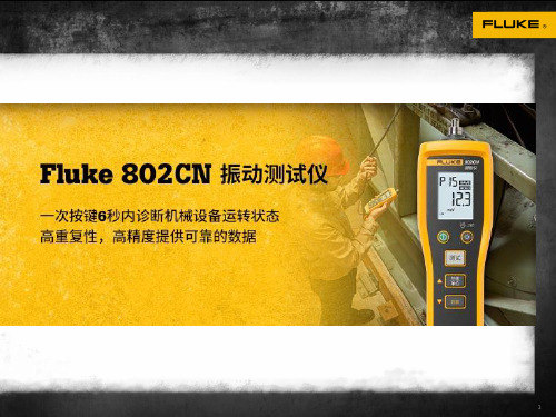
• 一键机械设备振动状态准确检测 • 机械设备诊断万用表
3
Fluke 802CN 核心卖点
• 重复性,精度高,满足基础测试产品核心要求 • 四种测试模式,不同工业现场测试需要 • 单位切换速度/位移/加速度一键切换 • 本地化的服务
4
如何使用802CN
5
为什么选择福禄克测振仪
• 更好的精度,更优的价格 • 没有假货仿货困扰 • 本地化服务及维修 • 福禄克品牌及产品线优势
Fluke 802 CN 一键式旋转设备诊断
1
为什么需要使用测振仪
简单的振动排查:通频振动状况/轴承测量
• 使用振动排查工具,依照预设报警等级检查数据,将其与 ISO 标准(或“不正常”决定。
2
福禄克802CN的设计理念
7
AD8027中文资料

10 +VS
– + – +
9 8 7 6
VOUTB –IN B +IN B DISABLE/SELECT B
图1 连接图(顶视图)
关断模式
无反相:VIN > |VS| + 200 mV 宽电源电压范围:2.7V至12 V 小型封装:SOIC-8、SOT-23-6、MSOP-10
ADI中文版数据手册是英文版数据手册的译文,敬请谅解翻译中可能存在的语言组织或翻译错误,ADI不对翻译中存在的差异或由此产生的错误负责。如需确认任何词语的准确性,请参考ADI提供 的最新英文版数据手册。
AD8027/AD8028
目录
技术规格 ........................................................................................... 3 绝对最大额定值.............................................................................. 6 最大功耗...................................................................................... 6 ESD警告....................................................................................... 6 典型工作特性 .................................................................................. 8 工作原理.................................................................................... 17 输入级 ........................................................................................ 17 交越选择.................................................................................... 17 输出级 ........................................................................................ 18 直流误差.................................................................................... 18 宽带运作 ......................................................................................... 19 电路考虑.................................................................................... 19 应用.................................................................................................. 21 使用SELECT引脚..................................................................... 21 驱动16位ADC........................................................................... 21 带通滤波器 ............................................................................... 22 设计工具和技术支持.............................................................. 22 外形尺寸 ......................................................................................... 23 订购指南.................................................................................... 24
马达驱动芯片大全

不可调
0.8欧 160度
0.4欧 150度 有
1欧 有 有
1.5欧 有 没有 没有 没有
有 有 有 有
AHX2021限流控制的优势 1)与其他玩具马达驱动IC比较,达到限制电流后,能够保持恒流输出,保护芯 片和马达不会烧毁,同时电流恒定,使马达维持充沛的动力。 2)限流可以调节,能够满足多种马达的限流要求。 3)在驱动转向马达的情况下,堵转达到限流后,堵转电流不随电源电压变化, 更省电。通过调整限流电阻,很容易匹配各种马达和电池。 4) 在恒流情况下,可进调整PWM频率,从而改善整体EMI干扰。
深圳市安浩芯科技有限公司
TEL:23008750
李‘S 13600161955
AHX2021、AHX2023与其他玩具马达驱动芯片的比较
AHX2021 AHX2023 DX5065 KX5008 GPY006A PJ701R PJ9110 PJ9120 PJ9130 RZ7881 RZ7888 RZ7889 RZ7889D
1A 2A 否
0.8A 1.5A 否
3A
3A
1A
2A
3A
3A
1.5A
4A
5A5.Βιβλιοθήκη A否否是是
否
否
否
否
PWM调制 恒流
有
没有,达 到峰值电 流,减小 电流。
没有,依 靠过热限 制电流。 有
没有
没有
没有
没有
没有
没有
有
有
有
限流可调节 内阻 过热保护
外置电路 调节
外置电路 调节
不可调
不可调
不可调
不可调
不可调
工作范围 最大驱动电 流 峰值电流 是否外界功 率管 限流控制
Monolithic Power eMotion System 智能电机模块评估套件 EVKT-MS
EVKT-MSM942038-24EVKT-MSM942038-24eMotion System TM Smart Motor ModuleEvaluation KitEvaluation Kit EVKT-MSM942038-24 ContentsPart Number EVKT-MSM942038-24Diameter (mm) 42 Power (W)38 Typical Voltage (V)24 InterfaceRS485# Part Number Item Quantity 1EVKT-MSM942038-24 BLDC motor withMMP742038-24 smart motor module installed 1 2eMotion System TMcommunication kitUSB communication interface with cable1FEATURESThe EVKT-MSM942038-24 evaluation kit is part of a family of fully integrated smart motor solutions for servo motor applications. This 42mm (NEMA 17), 38W motor integrates a brushless DC motor and a smart motor module. The user can program the system to operate in speed control mode, position control mode, or torque control mode. Two control interface options are available: an RS485 interface and a PULSE/DIR interface. Easy-to-use GUI software provides flexibility by allowing users to optimize the design online through the RS485 control interface. The parameters are saved in the motor module ’s non-volatile memory. A design guide for the GUI is available for download at .The smart motor modules can be ordered separately for customization into different motor types. The MMP742038-24 is the driver module part number used in the kit.The datasheet for the MMP742038-24 is available for download at .∙ 18V to 36V Input Voltage Range ∙ Max 38W Continuous Power Output ∙ 0.12N-m Rated Torque (0.36N-m Peak Torque)∙0.3° Position Resolution ∙ RS485 Interface and PULSE/DIR Interface ∙ Position, Speed, and Torque Control Modes ∙ Operating Temperature: 0°C to 70°C (Power Derated > 40°C) ∙ Storage Temperature: -40°C to +125°CORDERING INFORMATIONDESCRIPTIONEVKT-MSM942038-24 – eMOTION SYSTEM TM EVALUATION KITSmart Motor Module Evaluation KitParameter Condition Value UnitsInput voltage24 VOutput power0°C to40°C38 WPositionresolution0.3 °Nominal speed3000 rpmNominal torque0.12 N-mRotor inertia24 g-cm2Diameter42 mmShaft diameter 5 mmLength Body only 40 mmWeight300 gHARDWARE CONNECTIONSRECOMMENDED OPERATING CONDITIONSInput voltage ................................. 18V to 36VControl interface voltage ................ 0V to 5.5VMax pulse frequency .......................... 500kHzRS485 A/B voltage ........................ 0V to 5.5VRS485 common mode voltage ................±15VOperation temperature................. 0°C to 70°CStorage temperature ............. -40°C to +125°C EVALUATION KIT SPECIFICATIONSEVKT-MSM942038-24 – eMOTION SYSTEM TM EVALUATION KIT8 9 10 11 121 2 3 45 6 7Fault IndicationPower On IndicationT A = 25°C, V IN = 24V, unless otherwise noted.Pin NumberDesignation Pin Description RS485 Interface 1 EXT_5V5V input for firmware programming 2 B RS485 node B 3 AGND RS485 ground 4 A RS485 node A Power Interface5 GND Power ground6 R- Shunt resistor return node7 VIN Input power supply Control Interface8 COM- Common return 9 EN+ Enable input 10 PEND+ Position end output11 PUL+ Pulse input 12DIR+Direction inputPIN CONFIGURATIONTYPICAL PERFORMANCE CHARACTERISTICSEVKT-MSM942038-24 – eMOTION SYSTEM TM EVALUATION KITMECHANICAL DRAWINGEVKT-MSM942038-24。
正确的QN8027初始化程序20090723

正确的QN8027初始化程序如下:
1.写数据到QN8027寄存器0x00=0x81; //将QN8027所有寄存器复位到缺省值
2. 20ms延迟
3. 写数据到QN8027寄存器0x03=0x50; //设置QN8027为外部正旋波时钟输入(与硬件设计相关)
4. 写数据到QN8027寄存器0x04=0x33; //设置12MHz时钟频率(与硬件设计相关)
5. 写数据到QN8027寄存器0x00=0x41; //QN8027有限状态机校验
6. 写数据到QN8027寄存器0x00=0x01; // QN8027有限状态机校验
7.20ms延迟//增加20ms的延迟来等待QN8027有限状态机校验的完成
8. 写数据到QN8027寄存器0x18=0xE4; //改善信噪比SNR
9. 写数据到QN8027寄存器0x1B=0xF0; //使QN8027发射功率最大
10. 写数据到QN8027寄存器0x01=0x7E; //设置发射频率
11. 写数据到QN8027寄存器0x02=0xB9; //放弃QN8027 PA关闭功能当没有音频信号输入时
12. 写数据到QN8027寄存器0x00=0x22; //发射。
LEADER-LCM0827A3038F-扁平振动马达 产品规格说明书
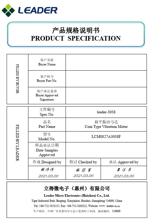
产品规格说明书PRODUCT SPECIFICATIONFILLED BY BUYER客户名称Buyer Name客户料号Buyer Part No.客户承认签章Buyer Approved SignaturesFILLED BY LEADER文件编号Spec No.leader-3038品名Part Name 扁平振动马达Coin Type Vibration Motor型号Model No.LCM0827A3038F样品承认日期Date Samples Approved 作成 Designed by检讨 Checked by 承认 Approved by张停停 2021.03.06张 冠 军2021.03.06王 远 东 2021.03.06立得微电子(惠州)有限公司Leader Micro Electronics (Huizhou) Co., Ltd.Tiger Industrial Park, Baigang, Xiaojinkou, Huizhui, Guangdong 516000, China Tel: +86-752-5853255, Fax: +86-752-5839222, Website: www. 生产地址:中国广东省惠州市小金口老虎岭工业园,邮政编码:516000规格书内容Contents of Specifications13. 外形图/ Mechanical Drawing 9/1011.环境管理物质/ Environmental Management Materials: 7/101. 适用范围/ Applicable Scope 1/102. 使用条件/ Operating Conditions 1/103. 测试条件/ Test Conditions 1/104. 初期电气性能/ Initial Electrical Characteristics 1/105. 机械性能/ Mechanical Characteristics 2/106. 耐久性能/ Reliability Characteristics 3/107. 标准测量方法/ Standard Measuring Method 5/108. 测量方法及回路图/ Measuring Method & Circuit Map 5/109. 使用注意事项/ Cautions in Use 6/1012. 包装/ Packaging 8/1010. 特性曲线图/ Characteristics Graph 6/10 14.更改记录/ Revision Records 10/102021.03.06(REV,0)说明书/Specification编号/No.: leader-30381/10项目/Item规格/Specification2-1额定电压Rated voltage 3.0V DC2-2使用电压范围Operating voltage 2.7~3.3V DC2-3旋转方向Rotation CW(clockwise) or CCW(contrary clockwise)2-4使用环境Operating environment-20~+60℃, 10~90%RH2-5保存环境Storage environment-30~+70℃, 10~90%RH项目/Item规格/Specification3-1温度Temperature25±3℃3-2湿度Humidity65±20% RH3-3气压Air Pressure1013±40 hPa3-4电源Power 稳压直流电流Constant DC Current项目/Item规格/Specification条件/Condition4-1额定转速Rated Speed 9,000 rpm Min额定电压下和额定负载下。
金龙振动马达(扁平振动马达) C0827B020F 规格书说明书
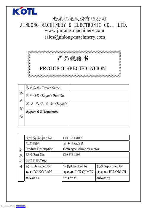
规格书内容/ ContentsApplication 1/8of1.适用范围/GeneralScopeConditions 1/8 2.使用条件/OperatingofMeasurement 1/8 3.测定条件/ConditionsCharacteristics 1/84.电气性能/Electrical5.机械性能/Mechanical Characteristics 2/86.耐久性能/Reliability Test 2/87.要求/Requirements after Reliability Tests 4/88.使用注意事项/Cautions for Use 5/89.包装/Packaging Description 6/810.外形图/Outline Drawings 7/811.更改记录/Records of Revisions 8/81. 适用范围/General Scope of Application本说明书适用于扁平式永磁直流电机C0827B020F 系列.This specification applies to coin type permanent-magnetic motors DC model C0827B020F.2. 使用条件/Operating Conditions3. 测定条件/Conditions of Measurement4. 电气性能/Electrical Characteristics项目/Item 规格/Specifications 2-1 额定电压 Rated voltage 3.0V DC 2-2 使用电压范围 Operating voltage 2.7~3.3V DC2-3 旋转方向 RotationCW (clockwise) or CCW (counter clockwise) 2-4 使用环境Operating environment -20~60,℃常湿/Ordinary Humidity:65±20%RH 2-5保存环境Storage environment-30~70,℃常湿/Ordinary Humidity:65±20%RH项目/Item 规格/Specification 3-1 温度Temperature 25±3℃ 3-2 湿度 Humidity 65±20% RH3-3 电源电压 Power supply稳压直流电源3.0V 。
首款中国研发制造的Fluke 802CN振动测试仪横空出世
首款中国研发制造的Fluke 802CN振动测试仪横空出
世
2015年10月22日,福禄克公司正式推出了Fluke 802CN振动测试仪,该产品是第一款由中国研发中心研发和设计,采用中文按钮和菜单为中国广大过程和制造业点检和维修客户定制的振动类测试仪器。
802CN定位于一键式机械设备振动评估,通过一次按键在6秒内获得旋转设备位移,速度,加速度等关键振动评估信息,帮助点检及维修人员高效的检测工厂中几乎所有的机械设备。
同时产品可以进行一键测试数据的记录并支持实时99组数据的回看。
为了满足工业现场不同的测试条件,802CN设计了四种测试方式:
普通测试模式:针对直接可接触的设备进行检测
加长杆测试模式:对于被包围或较难接触的设备进行测试。
QN8027 Datasheet

QN8027High Performance Digital FM Transmitter for Portable Devices________ General Description ________ ___________ Key Features __________The QN8027 is a high performance, low power, full-featured single-chip stereo FM transmitter designed for portable audio/video players, automotive accessories, cell phones, and GPS personal navigation devices. The QN8027 covers frequencies from 76 MHz to 108 MHz in 50/100/200 kHz step sizes for worldwide FM band support. The QN8027 also supports RDS/RBDS data transmit. The QN8027from stereo audio FM band personal low-spur MPX low-noise amplifier with An integrated calibration circuits and enable a programmable The QN8027’s minimum external a variety of applications. robust consistent process variations. An integrated voltage regulator enables direct connection to a battery and provides high PSRR for superior noise suppression. A low-power IDLE mode extends battery life.ESD protection is on all pins. The QN8027 is fabricated in highly reliable CMOS technology.• Worldwide FM Band Transmit• 76 MHz to 108 MHz full band tuning in 50/100/200 kHz step sizes • 50/75µs pre-emphasis• Ease of Integration• Small footprint, 3 x 3 x 0.95mm MSOP10• -25C to +85C operation• ESD protection on all input and output pads_____________________________ Typical Applications __________________________Cell Phones / PDAs / Smart Phones Portable Audio & Media PlayersGPS Personal Navigation Devices Automotive and AccessoriesCONTENTS1Functional Block Diagram (4)2Pin Assignments (5)3Electrical Specifications (6)4Functional Description (11)4.1Transmit Mode (11)4.2Idle Mode (11)4.3114.4114.5124.6125135.1I213615 725 8288.1288.2288.329REVISION HISTORY1 FUNCTIONAL BLOCK DIAGRAM2 PIN ASSIGNMENTS3 ELECTRICAL SPECIFICATIONSTable 2:Absolute Maximum RatingsTable 4:DC Characteristics(Vcc = 2.7 ~ 5.0 V, T A = -25 ~ 85 o C, unless otherwise noticed. Typical values are at Vcc = 3.3.V, f carrier=88 MHz and T A = 25o C).Table 6:Transmitter Characteristics(Vcc = 2.7 ~ 5.0 V, T A = -25 ~ 85 o C, unless otherwise noticed. Typical values are at Vcc = 3.3V, f carrier=88 MHz and T A = 25o C).Table 8:I C Interface Timing Characteristics(Vcc = 2.7 ~ 5.0 V, T A = -25 ~ 85 o C, unless otherwise noticed. Typical values are at Vcc = 3.3V and T A = 25o C).Figure 3:I2C Serial Control Interface Timing Diagram4 FUNCTIONAL DESCRIPTIONThe QN8027 is a high performance low power single chip FM transmitter IC that supports worldwide FM broadcast band operation. It has an IDLE mode for saving power. RDS/RBDS data service is also supported.4.1 Transmit ModeThe QN8027 transmitter uses a highly digitized architecture. The input left and right analog audio signals are first adjusted by VGA, and then digitized by two high resolution ADCs into the digital domain. Pre-emphasis and MPX encoding are then performed. If RDS mode is enabled, the RDS signal will also be mixed with the MPX signal and the combined output will be fed into a high performance digital FM modulator which generates FM signal at RF carrier4.24.3 serial interface.4.4 The QN8027 supports audio AGC, programmable pre-emphasis. When there is no audio signal for a pre-determined period, AGC will power down the transmitter. A peak detector is also integrated to measure the input audio level. User can program VGA based on the peak value.Stereo signal is generated by the MPX circuit. It combines the left and right channel signals in the following way:[][])36cos()()2cos()24cos()()()()()(000θπθπαθπ+++++−++=ft t d ft ft t R t L t R t L t m Here, L(t) and R(t) correspond to the audio signals on left and right channels respectively, f = 19 kHz, θ is the initial phase of pilot tone and α is the magnitude of pilot tone, and d(t) is RDS signal. In mono mode, only the L+R portion of audio signal is transmitted. The 19 kHz pilot tone is generated by the MPX circuit which contributes 9% of peak modulation, and RDS signal will contribute 2.1% of peak modulation.A pre-emphasis function is also integrated with both 75µs and 50µs time constants. The time constant can be programmed through the serial control interface.4.5 Channel SettingBy programming channel index CH[9:0], the RF channel can be set to any frequency between 76 MHz ~ 108 MHz in 50 kHz steps. The channel index and RF frequency have the following relationship:F RF = (76 + 0.05 x Channel Index), w here F RF is the RF frequency in MHz.The QN8027 has an integrated crystal oscillator and supports 12/24M Hz crystals. Alternatively, the QN8027 can be driven externally by clock source.4.75 CONTROL INTERFACE PROTOCOLThe QN8027 supports an I2C serial interface. At power-on, all register bits are set to default values.5.1 I2C Serial Control InterfaceThe QN8027 uses the Phillips I2C standard in the I2C serial interface.The I2C (L2) bus is a simple bi-directional bus interface. The bus requires only serial data (SDA) and serial clock (SCL) signals. The bus is 8-bit oriented. Each device is recognized with a unique address. Each register is also recognized with a unique address. The L2 bus operates with a maximum frequency of 400 kHz. Each data put on the SDA must be 8 bits long (Byte) from MSB to LSB and each byte sent should be acknowledged by an “ACK” bit. In case a byte is notThe timing diagrams below illustrate both write and read operations.6 USER CONTROL REGISTERS-------- THIS IS A PREVIEW LIST. Number and content of registers subject to change without notice -------- There are 19 user accessible control registers. All registers not listed below are for manufacturing use only.Table 9:Summary of User Control RegistersRegister Bit R/W Status:RO - R ead O nly: You can not program these bits.WO - W rite O nly: You can write and read these bits; the value you read back will be the same as written.R/W - R ead/W rite: You can write and read these bits; the value you read back can be different from the value written. Typically, the value is set by the chip itself.Word: SYSTEM Address: 00hWord: CH1 Address: 01hBit 7 (MSB) Bit 6 Bit 5 Bit 4 Bit 3 Bit 2 Bit 1Bit 0(LSB)ch[7] ch[6] ch[5] ch[4] ch[3] ch[2] ch[1] ch[0] wo wo wo wo wo wo wo woBit Symbol Default Description7:0 CH[7:0] 0000 0000 Lower 8 bits of 10-bit Channel index. Channel used for TX.Word: REG_XTL Address: 03hWord: CID2 Address: 06h (RO)Bit 7 (MSB) Bit 6 Bit 5 Bit 4 Bit 3 Bit 2 Bit 1Bit 0(LSB)cid3[3] cid3[2] cid3[1] cid3[0] cid4[3] cid4[2] cid4[1] cid4[0] ro ro ro ro ro ro ro roBit Symbol Default Description7:4 aud_pk[3:0] rrrr Audio peak value at ADC input is aud_pk[3:0]*45mV3 RDS_UPD r RDS TX: To transmit the 8 bytes in RDS0~RDS7, the user should togglethe register bit RDSRDY. Then the chip internally fetches these bytesafter completing transmitting the current group. Once the chip hasinternally fetched these bytes, it will toggle this bit, and the user can writein another group.2:0 FSM[2:0] rrr Top FSM state codeBit 7 (MSB) Bit 6 Bit 5 Bit 4 Bit 3 Bit 2 Bit 1Bit 0(LSB)rdsd1[7] rdsd1[6] rdsd1[5] rdsd1[4] rdsd1[3] rdsd1[2] rdsd1[1] rdsd1[0] wo wo wo wo wo wo wo woBit Symbol Default Description7:0 RDSD1[7:0] 0000 0000 RDS data byte 1Word: RDSD2 Address: 0AhBit 7 (MSB) Bit 6 Bit 5 Bit 4 Bit 3 Bit 2 Bit 1Bit 0(LSB)rdsd2[7] rdsd2[6] rdsd2[5] rdsd2[4] rdsd2[3] rdsd2[2] rdsd2[1] rdsd2[0] wo wo wo wo wo wo wo woWord: RDSD5 Address: 0DhBit 7 (MSB) Bit 6 Bit 5 Bit 4 Bit 3 Bit 2 Bit 1Bit 0(LSB)rdsd5[7] rdsd5[6] rdsd5[5] rdsd5[4] rdsd5[3] rdsd5[2] rdsd5[1] rdsd5[0] wo wo wo wo wo wo wo woWord: RDSD6 Address: 0EhBit Symbol Default Description7 TXPD_CLR 0 TX aud_pk clear signal: Audio peak value is max-hold and stored inaud_pk[3:0]. Once TXPD_CLR is toggled, the aud_pk value is clearedand restarted again.6:0 PA_TRGT[6:0] 111 1111 PA output power target is 0.62*PA_TRGT+71dBu. Valid values are 20-75.Word: FDEV Address: 11hBit 7 (MSB) Bit 6 Bit 5 Bit 4 Bit 3 Bit 2 Bit 1Bit 0(LSB)tx_fdev[7] tx_fdev[6] tx_fdev[5] tx_fdev[4] tx_fdev[3] tx_fdev[2] tx_fdev[1] tx_fdev[0] wo wo wo wo wo wo wo wo7 ORDERING INFORMATIONPart Number Description PackageQN8027-SANC The QN8027 is a high performance, low power, full-featured single-chip stereo FM transmitter designed for portable audio/video players,automotive accessories, cell phones, and GPS personal navigationdevices. 3x3 mm Body [MSOP10]8 PACKAGE DESCRIPTION10-Lead plastic package – 3x3 mm Body [MSOP]Notes:1. Pin 1 visual index feature may vary, but must be located within the area indicated in the drawing.2.Dimensioning and tolerance per ASME Y 14.5M.BSC: Basic Dimension. The theoretically exact value is shown without tolerance.Carrier Tape DimensionsNOTES:1. 2. 3.9 SOLDER REFLOW PROFILE9.1 Package Peak Reflow TemperatureQN8027 is assembled in a lead-free MSOP package. Since the geometrical size of QN8027 is 3 mm × 3 mm × 0.95 mm, the volume and thickness is in the category of volume<350 mm3 and thickness<1.6 mm in Table 4-2 of IPC/JEDEC J-STD-020C. The peak reflow temperature is:=T o260Cpoo9.3 Maximum Reflow TimesAll package reliability tests were performed and passed with a pre-condition procedure that repeat a reflow profile, which conforms to the requirements in Section 9.2,three (3) times.Quintic Corporation (USA) 3211 Scott Blvd., Suite 203 Santa Clara, CA 95054Tel: +1.408.970.8808Fax: +1.408.970.8829Email: s upport@ Web: w Quintic Microelectronics (China) Building 8 B-301A Tsinghua Science Park 1st East Zhongguancun Rd, Haidian Beijing, China 100084Tel: +86 (10) 8215-1997Fax: +86 (10) 8215-1570Web: w Quintic Microelectronics and Quintic are trademarks of Quintic Corporation. All Rights Reserved.。
手机震动马达知识
iPhone 6s的Taptic Engine究竟有何特别?
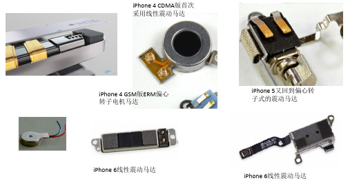
实际上iPhone 6与6 Plus已经开始采用线性震动马达,而且震动马达的体积明显变大了很多,尤其是iPhone 6(很诡异的 是,6 Plus的震动马达反而更小,大概是期望6 Plus的电池容量可以比大更大),在寸土寸金的iPhone上占用这么大空间, 似乎很少有组件敢居此种魄力。
更重要的是,在iOS多样化的信息提示震动选项里(很多人可能不知道,iPhone支持不同节奏的震动提示,比如心跳、 断奏、交响乐等),iPhone 6s多出了一个名为同步的默认震动选项,它能够几乎达到与提示音完全同步的震动节奏, 这如前文所说需要非常出色的震动启停表现,过往的iPhone,即便是iPhone 6这种也已经用上线性震动马达的设备也是 做不到的
手机振动马达是直流有刷电机电机 的供应商的一种,用于 实现手机的振动功能,当收到短信或电话时,电动机启动, 带动偏心轮做高速旋转,从而产生振动,如今的手机振动 马达体积越来越小,以适应日益轻薄的手机机身的需要。
手机振动马达使手机震动的原因 (1) 由金属棒的偏心转动造成。 由于金属棒在所在的密封金属盒内高速转动, 通过摩擦力引起金属盒的内部空气也做剧烈运动。 从而引起整个密封的金 属盒振动,进而带动整个手机产生振动。有上述计算可知,金属棒做高速 转动的 能量所占份额很大,故此原因为手机产生振动的主因。 (2) 由重心不稳造成。 由于震动马达的转动轴上所连的金属棒并不是按几何对 3 称的方式布置的,故震动马达的转动轴会 沿质心所在的方向转过一个偏 角。故造成金属棒实际上并不是在水平面内转动的。在转动中,质心所在 的位置会随金属棒的位置的改变而改变, 故金属棒的转动平面也是与水平 面呈一定的夹角不断变化的。 这种质心在一定的空间范围内不断变化的运 动必将造成这个物体的位置移动。当变化较小且十分频繁时, 即在宏观上 表现为振动。
动平衡技术要求
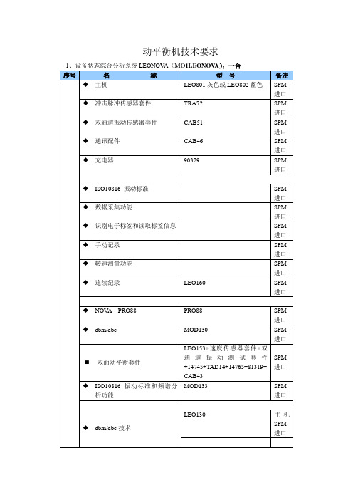
动平衡机技术要求标准:ISO9001:2000测量参数:位移、速度、加速度峰值、峰峰值或有效值,峰值因子,峭度,歪度,噪声频率范围: 0.5~40000Hz。
窗口:汉宁窗频谱线数:400,800,1600,3200,6400,12800通道数:双通道频率单位:Hz,CPM测点:每个点可存储100个纪录软件:Windows CE 操作平台电池:聪明的充电与电量指示,锂电池,正常使用超过8小时显示:交互式的TFT彩色触摸屏,图形可按时间和刻度缩放通讯:RS232或USB通讯接口处理器:400 MHz Intel. XScale. 高速处理器存储器:1GB内存,32MB闪存;2、现场动平衡仪两套名称数量备注标配TH20002 原装进口主机光电传感器 2 原装进口速度传感器8 原装进口10M测试电缆10 原装进口20M测试电缆 5 原装进口反光带 2 原装50电涡流传感器 4 原装进口低频速度传感器 4 原装进口技术参数要求动平衡工作转速:600-30000RPM(速度传感器)30-30000RPM(电涡流传感器)幅值量值:0-8000um相位跟踪:360度内±1度3、设备安装调试及保修A、在仪器到达现场后,双方对设备进行验收,送货等费用由供货方负责。
B、按设备配置明细、仪器性能指标及瑞典SPM公司技术规格,出厂报告和数量进行验收。
双方签字认可。
仪器运输过程中造成的损坏和零部件缺项,由供货方负责与厂商协商更换,设备附有产品出厂鉴定证书。
C、在设备安装和使用过程中,供货方协助并培训正确安装和使用设备。
D、如设备自身原因不能达到验收或者安装要求,供货方有责任维修或更换方案,直到达到验收指标。
E、供货方提供仪器制造依据的标准,并提供与仪器相关的标准。
提供所有产品的整套手册,包括使用手册、出厂合格检验证书以及有关资料。
提供中文操作手册印刷版及电子版中、英文操作手册。
F、仪器保修期为产品验收合格后12个月,在保修期内由于非人为因素,造成损坏由供货方无偿负责解决4、服务及其它A、质保期后供货方继续免费提供技术支持,有偿提供维修服务和零部件,保证甲方所购仪器长期稳定运转。
GMW 8702_罗清 试验测试标准

试验对象及试验装置的定义和准备© 版权2007 所有权归通用汽车公司1/7/2024 发起部门: 北美工程标准1 / 51 适用范围说明:本标准的任何内容都不能取代法律法规的规定,除非从有关方面获得特别的许可。
说明:如果出现英语版本与当地语言版本在某些条文上的含义不一致,应以英语版本为准。
1.1 目的。
为噪声振动的试验、分析、设定基准和开发,标准化定义一套试验对象和试验装置。
1.2 前言。
统一关于车辆试件以及试验所需装置的定义有利于技术交流,改善交流的效果。
1.3 适用性。
本试验标准适用于评价所有的子系统、零部件和车辆。
2 参考目录说明: 除非特别指明,否则只能引用最新的获得批准的标准或规范。
2.1 外部标准/规范。
无2.2 GM 标准/规范。
无2.3 其他参考文献。
无3 资源3.1 设施。
不适用。
3.2 设备。
不适用。
3.3 试验车辆/试验零部件。
不适用。
3.4 试验时间。
不适用。
日历时间: 天 试验小时数: 小时 协调小时数:小时3.5 试验要求的信息。
不适用。
3.6 人员/技能。
不适用。
4 程序4.1 准备。
4.1.1 在隔振件的界面处测量频率响应函数(FRF ):对于激振位置的试验金属构件的一般性指导意见(包括加速度导纳、导纳、声学灵敏度等试验)当在一个隔振件的界面测试FRF 时,目标是在该隔振器的“弹性中心”处激励相应的试件,为此可以将隔振器支架金属构件固定在试件上,隔振器附加装置的状况将会影响测试的质量。
但是,成本、时间因素,以及对于损伤试件的限制,有时让利用隔振器支架做试验变成一件不可能的事情。
下列方法针对试验对象和装置的准备工作。
在附录A 中描述了几种试验工况的情形。
4.1.1.1优先考虑的试验装置:用螺栓将隔振器支架金属构件固定在试件上;激振作用点应该位于所理解的隔振器的弹性中心;可以采用挤压或者焚烧的办法去除隔振器的橡胶部分,如果有液压的构件也要清除掉;所有非橡胶(非液压)的悬置部分均需保留;检查是否达到推荐的螺栓扭矩值以符合产品的设计意向。
