TC-500说明书
001 TC500系统操作手册

使用说明书TC500系统TC500控制系统手册欢迎使用美卓矿机的TC500系统。
该系统由美卓矿机研发,并且广泛运用于美卓矿机HP系列破碎机。
对该系列破碎机稳定安全可靠的运用起到至关重要的作用,同时,也大大提高了该系列破碎机的产能,受到广大海内外客户的好评。
一、系统概述该控制系统主要采用A-B公司的上位机软件RSView32和MicLogix 1500 PLC系统。
上位机PC用EtherNet网络通过交换机和1761-NET-ENI 网络适配器完成数据交换,1761-NET-ENI将EterNet转换成RS232通讯协议,从而完成PC和PLC的通讯。
同时,每台PLC控制一台破碎机。
通讯系统如下图所示:在TC500控制系统中,同时还包括手动控制系统和自动控制系统。
以满足各种工况。
二、手动控制该功能,主要由专业服务人员安装调试时使用。
同时,也可以在PLC系统完全瘫痪的时候,为了保证连续生产时使用。
使用该功能时,请先将手自动选择开关,推到手动档,这样,控制柜面板上的二位开关才起作用。
在工作中,请按照规程,先启动润滑油加热器,温度达到工艺要求后,再打开润滑泵,运行2分钟左右后,方可启动破碎机。
之后才可以启动给料机。
注意,关于给料机,由于该电机由变频器控制,在自动的时候,由PLC控制起停和通过4-20MA信号调试,所以如果在手动的时候也需要调速和手动起停时,必须对变频器相关参数进行修改。
并且,由变频器面板上按钮调速。
具体参数如下表所示:序号功能代码名称LCD画面显示设置值设置值功能描述备注1F01频率设定1F01频率设定10键盘面板设定2F02运行操作F02运行操作0由操作键控制电机起停3F03最高频率1F03最高频率150最高输出频率4F07加速时间1F07加速时间16电机达速时间5F08减速时间1F08减速时间6电机减速到停机时间6E24Y5AY5C功能E24 Y5功能0运行反馈注:根据现场使用变频器修改参数需要停机的时候,先停止给料机,等破碎腔无料后停止破碎机,关闭破碎机后,让润滑泵继续运行10分钟后,方可关闭润滑泵。
TC系列电子天平使用说明书

TC系列电子天平使用说明书(适用于TC3K、TC6K、TC10K、TC20K、TC30K、TC3KA、TC6KA、 TC10KA、TC20KA、TC30KA、TC10KB、TC20KB)一.概述TC系列电子天平是常熟市双杰测试仪器厂采用工业级的高精度传感器和测量电路以及“双杰”专用的单片计算机系统精心设计和制作而成的高品质电子称重仪器,先进的技术、优良的选材、精湛的制作工艺和严格的检测手段,使该系列电子天平具备了极其完美的优点:1.精度及灵敏度高,反应速度快;2.采用高精度应变式称重传感器,克服了一般的高精度电磁式电子天平不能称量铁、镍等导磁物质的缺陷。
3.线路模式先进,选材和制作工艺精良,因而产品可靠性高,抗干扰能力强,使用寿命长,长期使用稳定性好,可以适应恶劣的使用环境并长时间连续工作;4.具有自动校正功能;5.采用高亮度绿色大显示器,显示清晰,读数直观;6.具有单位转换功能,可在“kg”(千克)→“lb”(磅)之间任意转换;7.天平配置有数据输出接口和打印按键,可直接连接打印机进行数据打印,更可直接与计算机接口,进行数据的采集、统计,同时计算机也可以通过接口来控制天平的工作,对天平进行实时的远程控制;8.天平具有计数功能,可方便用户对大批量的物件进行计数。
二. 规格及性能指标型 号 TC3K TC6K TC10K TC10KB TC20K TC20KB TC30K最大秤量 3kg 6kg 10kg 10kg 20kg 20kg 30kg分 辨 率 0.1g 0.1g 1g 0.1g 1g 0.1g 1g检定分度 10d 10d 10d 10d 10d 10d 10d去皮范围 3kg 6kg 10kg 10kg 20kg 20kg 30kg校准重量 2kg 5kg 10kg 10kg 20kg 20kg 20kg秤台尺寸 340mm×220mm体 积 350 (W)×327 (D)×100 (H) mm供 电 AC 220V ± 10% 50Hz ± 1Hz使用温度 0-40°C使用湿度 ≤80% R.H型 号 TC3KA TC6KA TC10KA TC20KA TC30KA最大秤量 3kg 6kg 10kg 20kg 30kg分 辨 率 0.5g 1g 2g 5g 5g检定分度 10d 10d 10d 10d 10d去皮范围 3kg 6kg 10kg 20kg 30kg校准重量 2kg 5kg 10kg 20kg 20kg秤台尺寸 340mm×220mm体 积 350 (W)×327 (D)× 100 (H) mm供 电 AC 220V ± 10% 50Hz ± 1Hz使用温度 0-40°C使用湿度 ≤ 80% R.H三. 操作方法1. 接通电源,调整好水平,按开关键,显示窗显示“F----1”到“F----9”,稳定一段时间后出现“0”,接下来应通电预热15分钟。
科瑞爱特 CT55500KVVA 系列三相工频电力专用 UPS 电源 使用手册说明书

科瑞爱特CreateU s e r M a n u a lC T50K V A系列三相工频电力专用U P S电源声明本资料著作权属科瑞爱特科技开发有限公司所有。
未经著作权人书面许可,任何单位或个人不得以任何方式摘录、复制或翻译。
侵权必究。
是科瑞爱特科技开发有限公司的注册商标。
科瑞爱特产品的名称和标志是科瑞爱特的专有标志或注册商标。
在未经科瑞爱特或第三方商标或商名所有者事先书面同意的情况下,本手册不以任何方式授予阅读者任何使用本手册上出现的任何标记的许可或权利。
本产品符合关于环境保护和人身安全方面的设计要求,产品的存放、使用和弃置应遵照产品手册、相关合同或相关国家法律、法规的要求进行。
由于产品和技术的不断更新、完善,本资料中的内容可能与实际产品不完全相符,敬请谅解。
如需查询产品的更新情况,请联系那个地办事处。
若需了解最新的资料信息,请访问网站:感谢您选择三相工频电力专用UPS电源!尊敬的用户:首先感谢您选用我们的产品,从现在开始我们将成为朋友!我们非常高兴向您提供这一系列电源产品,希望它在未来的岁月里为您提供方便、可靠的服务,保证您的设备安全运作。
为了您的安全和更好的使用该系列电源,请您在安装使用前务必仔细阅读此使用手册!如果您对本手册的内容有疑问或不明确之处,请您在使用逆变电源产品前与我们联系。
警告:不要拆卸电力U P S电源上的任何外壳或器件。
设备内部零件带有致命性的电压或存有高能量的危险!目录第一章 序言 (5)1.1 注意事项 (5)1.2 开箱检查 (6)1.3 储存环境 (6)1.4 搬运 (6)第二章 产品简介 (7)2.1 产品外观 (7)2.2 工作原理 (9)2.3 主要技术参数 (10)2.4 保护功能 (11)2.5 工作环境 (11)第三章 安装运行 (12)3.1 安装准备 (12)3.2 安装位置 (12)3.3 安装接线 (12)3.4 前面板操作和显示示意图及说明 (13)3.5 UPS电源试运行 (14)3.6 UPS电源的正常启动、关闭操作步骤 (15)第四章 显示异常信息和报警信号 (15)4.1 常见故障的原因及处理方法 (15)第五章 维护保养和售后服务 (16)5.1 维护保养 (16)5.2 售后服务 (16)第一章 序言三相工频电力专用UPS电源是为了电力保障,专为电力、通信系统设计,是一种将市电及电池的电能转化为净化的交流电能的变换装置,用以给计算机和其他电气设备提供可使用的连续交流电源,以备市电的不稳定及断电。
TC系列肩无疆土的温度校准设备说明书

TC SERIESPORTABLE & ACCURATE TEMPERATURE CALIBRATION MADE EASYLike most temperature calibrators you’ll find in this catalog, the TC Series generates true thermal references, not electronically-simulated ones. The TC Series’ lightweight, compact design makes them ideal for calibrating your temperature sensors on-site. All Tek Know calibrators come with interchangeable inserts that can be drilled with single or multiple immersion chambers to meet the specifications of your sensors.Programmable in either Celsius or Fahrenheit, the two-button operation allows for easy programming. And with the TC Series, obtaining true reference temperatures has never been easier. Simply place the sensor to be tested inside the well and set the temperature. The dual line display will show both the true and set temperature; once stabilization occurs, read the temperature and recalibrate the process or sensor. Tek Know calibrators may be used for calibration of thermocouples, thermistors and RTD sensors, or complete temperature loops.• T rue CalibrationProvides true temperature references, not simulated ones• C ompact DesignMakes it highly portable and ideal for field use• C ommunications PortRS-232 interface is standard, with FREE Windows TM -based software for semi-automatic calibration• Thermal Switch Test • E asy-To-Use 2-Button Operation • A ll Kits Include:Probe inserts, thermal switch leads, calibration certificate, instruction manual, industrial strength carrying case and SC200 SoftwareFREE SOFTWARE!SC200 Temperature Calibration SoftwareThe SC200 software package is a calibration tool which allows for fully-automatic or semi-automatic calibration, as well as a calibration management database. This software is useful in creating and maintaining the extensive documentation required by ISO and QS 9000. It contains databases for storing calibration programs, last calibration date, and company information; as well as true values and deviations, both in percentages and absolute values.The software can also be used to completely automate your calibration process. Used in conjunction with our SM300 Signal Master, you can eliminate the need to watch over your calibration while it runs. Just set it up and come back later to print out the certificate.• C ommunicationsCommunicates with SM300 and TC calibrators using RS232 serial ports. Drivers available for other instruments, including Beamex and Honeywell• S torageStores calibrations and calibration setups• D isplayShows on screen settling response at each calibration point. Up to 20 points• T hree modesCan be used in manual, semi- or fully-automatic modeTC150 This calibrator can generate both an ice point reference and a boiling point reference in one portable unit, making it theoptimal choice for food, dairy and biotechnology requirements.TC400 & TC650 For higher temperature applications, in particular calibration of J and K thermocouples up to 650°C (1192°F).TC600M This calibrator can maintain high accuracy and stability under the most severe conditions, and is therefore thepopular choice for offshore rigs and leading ship owners. As the TC600M was designed for the demanding needs of the marine industry, it is also ideal for field use in power utilities, petro chemical processing and the automotive industry.TC150 TC400 TC600M TC650TEMPERATURE RANGE -40°C* to 50°C (122°F) to 50°C (122°F) to 50°C (122°F) to150°C (302°F) 400°C (752°F) 600°C (1112°F) 650°C (1202°F)ACCURACY ±0.3°C ±0.3°C 1°C ±0.5°CSTABILITY ±0.03°C ±0.03°C 0.1°C ±0.05°CRESOLUTION 0.01° 0.01° 0.01° 0.01°COOLING TIME <20 min.AMBIENT TO MINIMUMHEATING TIMEAMBIENT TO MAXIMUM <15 min. <18 min. <18 min. <20 min.THERMAL SWITCH TEST Yes Yes Yes YesWELL DIMENSIONS 3/4” x 4.4” 1” x 6” 1” x 6” 1” x 6”OUTPUT RS232 RS232 RS232 RS232WEIGHT 15 lbs. 16 lbs. 16 lbs. 16 lbs.CALIBRATOR DIMENSIONS 8” x 5” x 11.5” 8” x 5” x 11.5” 8” x 5” x 11.5” 8” x 5” x 11.5”POWER 110V or 240 VAC 110V or 240 VAC 110V or 240 VAC 110V or 240 VAC INSERT FOR O.D. PROBE 1/8” & 3/16” 1/4” & 3/16” 3/16” 1/4” & 3/16”* below ambientSPECIFICATIONSTC SERIESIncluded in standard delivery: RS-232 interface, test cable for thermostats, 2-piece insertion tube, 1/8“ & 3/16 “, (1-1/8“ insert only for TC600M) calibration certificate, carrying case, 1 pc tool for changing insertion tubes, instruction manual, mains cableTC150Temperature Calibrator TC150, -40°C below ambient to 150°C (302°F) $ 5,350 TC400Temperature Calibrator TC400, Ambient to 400°C (752°F) 3,995 TC600M Temperature Calibrator TC600M, Ambient to 600°C (1112°F) 3,995 TC650Temperature Calibrator TC650, Ambient to 650°C (1202°F) 4,495 TC-INS-H-B Insert for TC400/TC600M/TC650, undrilled 140 TC-INS-H-18Insert for TC400/TC600M/TC650, 1/8” 175 TC-INS-H-316Insert for TC400/TC600M/TC650, 3/16” 175 TC-INS-H-14Insert for TC400/TC600M/TC650, 1/4” 175 TC-INS-H-38Insert for TC400/TC600M/TC650, 3/8” 175 TC-INS-H-12Insert for TC400/TC600M/TC650, 1/2” 175 TC-INS-H-1814Insert for TC400/TC600M/TC650, 1/8” + 1/4” 250 TC-INS-H-1414Insert for TC400/TC600M/TC650, 1/4” + 1/4” 250 TC-INS-L-B Insert for TC150, undrilled 130 TC-INS-L-18Insert for TC150, 1/8” 150 TC-INS-L-316Insert for TC150, 3/16” 150 TC-INS-L-14Insert for TC150, 1/4” 150 TC-INS-L-38Insert for TC150, 3/8” 150 TC-INS-L-12Insert for TC150, 1/2” 150 TC-INS-L-1814Insert for TC150, 1/8” + 1/4” 210 TC-INS-L-1414Insert for TC150, 1/4” + 1/4” 210TC-OIL Oil kit for TC150 cooling calibrators45TC SERIES, CONTINUED。
HYT TC-500S 说明书
X05031图标说明本说明书中会使用以下图标,各图标含义如下:注意:表示可能会损坏对讲机的事项。
术语说明本说明书中会使用以下关键术语:按键操作短按:按下并快速松开。
长按:按住并保持 1 秒以上。
按住:一直按住该按键。
用户模式用户模式即关机状态下,顺时针旋转【电源开关/音量控制】旋钮开机后所进入的操作模式。
CTCSS/CDCSS即亚音频/亚音数码,该技术可避免接收不相关的呼叫。
版权信息HYT 和 Hytera 为海能达通信股份有限公司(原深圳市好易通科技有限公司)在中华人民共和国和世界其它国家和/或地区的商标或注册商标。
我们仅对我司的商标及产品名称享有所有权,本说明书中可能提及的其它商标和产品名称为各自所有者所有。
本手册介绍的产品中可能包括存储于内存或其它媒介中的计算机程序。
海能达对此等程序享有的专有权利受中华人民共和国或其它国家及相关国际法的保护。
购买本产品并不意味着海能达以明示或暗示方式向购买者授予有关此等电脑程序的权益。
未经海能达事先书面授权,任何企业、组织或个人不得对计算机程序进行任何形式的复制、更改、散发、反编译和反向工程。
免责声明本手册在编制过程中力求内容的准确性与完整性,但对于可能出现的错误或疏漏,海能达不承担任何责任。
由于技术的不断发展,海能达保留不予通知而更改产品设计与规格的权利。
未经海能达事先书面授权,不得以任何形式对本手册进行复制、修改、翻译和散发。
如需更多信息或对本手册有任何建议,欢迎访问我们的网站:,或拨打海能达免费服务热线 400-830-7020。
检查包装内物品--------------------------------------------------2熟悉本机--------------------------------------------------------3部件介绍-------------------------------------------------------------------3可编程键-------------------------------------------------------------------4用前准备--------------------------------------------------------5给电池充电-----------------------------------------------------------------5附件安装-------------------------------------------------------------------6状态指示--------------------------------------------------------8基本操作--------------------------------------------------------8开机与关机-----------------------------------------------------------------8调节音量-------------------------------------------------------------------8选择信道-------------------------------------------------------------------8发射和接收-----------------------------------------------------------------8功能与操作------------------------------------------------------9亚音频/亚音数码 (CTCSS/CDCSS)----------------------------------------------9超时禁发-------------------------------------------------------------------9功率调整-------------------------------------------------------------------9监听-----------------------------------------------------------------------9静噪打开-------------------------------------------------------------------10扫描-----------------------------------------------------------------------10声控-----------------------------------------------------------------------11电池电量指示---------------------------------------------------------------11低电量告警-----------------------------------------------------------------12信道锁定-------------------------------------------------------------------12省电模式-------------------------------------------------------------------12繁忙信道锁定---------------------------------------------------------------12故障处理指南----------------------------------------------------13保养和清洁------------------------------------------------------14质量保证和维修条款----------------------------------------------14选购附件--------------------------------------------------------16包装盒内含有以下物件。
TC500说明书
2安装2 安装插图说明…………………………………………………..………………..… 2-2 抬举和移动仪器……………………………………………..……………..… 2-3 仪器安装………………………………………………………………..………2-4 设备要求………………………………………………………………..………2-7 电源安装………………………………………………………………..………2-9 国内电源安装………………………………………. .…………..………2-9 电源选择……………………………………………. ..…………..…… 2-10 国际电源安装……………………………………. ..……………..…… 2-12 交流电缆的技术规格………………………………………..…… 2-12 电极炉冷却系统………………………………………………………..…… 2-13 入口气体净化试剂的安装……………………………………………..…… 2-15 测量气体净化试剂的安装……………………………………………..…… 2-16 氧气和水分吸收观的安装……………………………………………..…… 2-18 吸尘器的安装………………………………………………………………………… 2-20 插图图2-1………………………tc-500后面板图…………………………………………………2-8 图2-2………………………电压选择图示………………………………………………………2-11 图2-3………………………添加冷却水图………………………………………………………2-14 图2-4………………………试剂管充填图………………………………………………………2-17图2-5...........................除氧气和水分试剂管帽的拆卸图 (2)-19 图2-6………………………吸尘器的安装图……………………………………………………2-20 抬举和移动仪器仪器重量大约为370磅(168kg)。
海能达TC-500经济型商业无线对讲机说明书

次。
电池电力在充电后也持续不了 z 电池的寿命已到。请更换电池。
多久。
不能与组内的其他成员对话。 z 确认您所使用的频率和亚音频信号音是否
与组内的其他成员相同。
z 组内的其他成员可能离得太远。确认您是否
在其他对讲机的有效范围之内。
信道中出现其他(非组员)的声 音。
z
请改变亚音频信号音。这时,务必改变组内 所有对讲机的信号音。
产品检查
请小心打开包装盒,确认盒内是否有下表列出的物品;若您发现本产品及其附件在搬运中有 任何丢失或损坏,请立即与您的经销商联系。
附件表
物品 天线* 电池充电器 火牛 Ni-MH 电池组 皮带夹 挂绳 使用说明书 保修卡 合格证
数量 1 1 1 1 1 1 1 1 1
*天线标识: 400-420MHz:红色; 450-470MHz:白色; 136-150MHz:蓝色; 150-174MHz:绿色。
3
电池信息
充电注意事项
作为选件的电池在出厂时没有进行充电,请在使用前对新的或者长时间未经使用的充电电池 进行充电。充电/放电循环两三次将可以使电池容量达到最佳状态。当发现电池电力低微时, 需对电池进行充电或更换电池。 注意: ★ 请勿使电池的端子短路或将电池投入火中。 ★ 电池装在对讲机上时可以充电,但需将对讲机关机,以保证电池充满。 ★ 不充电时,不要把对讲机和电池留在充电器上,连续不断充电将缩短电池寿命。 ★ 不要将充满电的电池再放回到充电器上去再“加电”,因为这种操作会显著降低电池的
电池省电
当信道未收到信号或无操作时间持续10秒钟以上时,电池省电功能启动。在接收信号或进 行操作时,电池省电功能自动停止。
电池电量不足告警
电池电量不足告警提醒您对电池充电。 如果电池电压在发射中低于预定值,状态指示灯会闪烁红灯。当“嘟”音响起时,对讲机将 停止发射。请更换电池或对电池充电。
TC5000系列数显拉力试验机使用说明书

TC5000系列数显拉力试验机使用说明书单数显拉伸试验采集系统主要技术指标:1、测量最大负荷0-3500000N2、拉力传感器标称量程选择:5N,10N,15N,20N,25N,50N,75N,100N,250N,500N,750N,1000N,2500N,5000N, 7500N,10000N,20000N,30000N,40000N, 50000N,60000N,70000N,80000N, 100000N,200000N,300000N, 400000N, 500000N,600000N,700000N,800000N,1000000N.1500000N, 2000000N,2500000N,3000000N,3500000N,新增加300N,3000N,90000N (定货必须按以上标称规格确定传感器量程)3、分辩能力15位(最小变量):0.002N(5-100N),0.02N(250-1000N),0.2N(2500-10000N),2N(20000-50000N),大于50000N时分辩精度为:传感器标称量程XXXXXXN/300004、系统精度:小于0.8%。
5、显示范围:0.001~3500000N6、电源电压:AC 2220V±20V单数显拉伸试验采集系统面板按键功能:1、试验键/数减键▽:A:在常规状态下按此键自动清力值为零,试验开始,试验灯闪烁。
B:在设置状态下按该键可对设置项目的参数起到减小的作用。
2、记录键/设置键: A:在试验状态下按此键可记录当前试验力值,最多可记录8个力值。
B:在常规状态下长时间按下此键达到5秒以上系统自动进入设置区,进入设置区后,用户可对试样截面积(dJ)、停止于X%(dH)、量程(dC)进行修改。
进入设置区后还是通过按放“设置键”切换设置项目dJ/dH/ dC。
要对设置项目参数修改请按“数减键▽”或“数增键△”。
注意要对量程(dC)进行修改必需超长时间按下“数减键▽”或“数增键△”达到10秒以上量程才改变。
TC系列 智能温控表使用说明书

智能温控表使用说明书本说明书对温控表设置、配线及各部分名称等进行说明,使用本产品前,请认真阅读本说明书,在理解内容的基础上正确使用。
并请妥善保存,以便需要时参考。
⊙支持多种热电偶、热电阻信号类型⊙采用模糊PID 控制算法,且自整定无过冲⊙多种控制方式可选,具体请参照OT 参数⊙RUN/STOP,运行/停止功能一键切换特点KKTCC02A-A/1-202009032、隔离模式框图:固态继电器输出绝缘电阻静电放电脉冲群抗扰度浪涌抗扰度电压暂降及短时中断抗扰度隔离耐压DC 24V 脉冲电平,带载<30mA 输入、输出、电源对机壳>20MΩIEC/EN61000-4-2 Contact ±4KV /Air ±8KV perf.Criteria B IEC/EN61000-4-4 ±2KV perf.Criteria B IEC/EN61000-4-5 ±2KV perf.Criteria BIEC/EN61000-4-29 0%~70% perf.Criteria B信号输入与输出及电源1500VAC 1min,60V 以下低压电路之间DC500V,1min 整机重量约 400g机壳材质面贴材质停电数据保护面板防护等级安全标准外壳与面板基架PC/ABS (难燃度UL94V-0)PET(F150/F200)10年,可写数据次数100万次IP65(IEC60529)IEC61010-1 过电压分类Ⅱ,污染等级2,等级Ⅱ(加强绝缘)3、测量信号参数表:1、电气参数表:采样速度2次每秒供电电源继电器容量AC 250V /3A 额定负载寿命大于10万次AC/DC 100~240V (85-265V)三、主要技术参数二、常规型号说明一、仪表型号周围环境条件整机功耗存贮环境< 6VA室内使用,温度:0~50℃ 无结露,湿度:<85%RH,海拔小于2000m -10~60℃,无结露SSR与继电器输出型 号控制输出功能1报警接点TC-□-M1□:外形尺寸可选E:版本1:一路报警输出 2:两路报警 空: 无报警功能4: 48W*48H*100L 6:48W*96H*100L 7:72W*72H*100L 8:96W*48H*100L 9:96W*96H*100LTC系列温控表注意:选择加热冷却控制方式时,如还需报警功能,请选择带两路报警的型号。
TC系列大称量电子天平中文操作手册

一.概述TC-K系列电子天平是常熟市双杰测试仪器厂采用工业级的高精度传感器和测量电路以及“双杰”专用的单片机计算机系统精心设计和制作而成的高品质电子称重仪器,已广泛应用于各行各业的各种用途的称重测量,检测检验,对提高产品质量、经济效益及工作效率都起到了重要作用。
该系列电子天平具有以下特点:1.精度及灵敏度高,反应速度快;2.线路模式先进,选材和制作工艺精良,因而产品可靠性高,抗干扰能力强,使用寿命长,长期使用稳定性好,可以适应恶劣的使用环境并长时间连续工作。
3.交直流两用功能。
4.具有自动校正功能。
5.采用高清晰度LCD大显示器,显示清晰,读数直观,并有背光功能。
6.具有单位转换功能,可在“kg”(千克)→“lb”(磅)之间任意转换;7.天平配置有数据输出接口和打印按键,可直接连接打印机进行数据打印,更可直接与计算机接口,进行数据的采集、统计,同时,计算机也可以通过接口来控制天平的工作,对天平进行实时的远程控制。
8.天平设计有计数功能, 可方便用户对大批量的物件进行计数。
9.大容量充电电池,充满一次可以连续使用60小时以上。
10.开机显示电池电压,当电池电压不足时自动关机,保护充电电池。
11、精度等级:TC-K系列电子天平符合JB5374-91《电子天平》标准以及JJG1036-2008检定规程三级天平的要求。
二. 型号规格及技术参数型号 TC60K TC100K TC150K TC200K TC300K 最大称量 60kg 100kg 150kg 200kg 300kg分辨率 1g 1g 5g 10g 10g 检定分度值 10d 10d 10d 10d 10d去皮范围 60kg 100kg 150kg 200kg 300kg 校准重量 50kg 100kg 100kg 200kg 200kg 秤盘尺寸 520mm×420mm供电 AC 220V±10% 50Hz±1Hz DC6V/4AH/20HR 充电电池 使用温度 0-40°C使用湿度 ≤ 80% R.H型号 TC60KA TC100KA TC150KA TC300KA TC600KA 最大称量 60kg 100kg 150kg 300kg 600kg 分辨率 5g 10g 20g 50g 100g 检定分度值 10d 10d 10d 10d 10d 去皮范围 60kg 100kg 150kg 300kg 600kg 校准重量 50kg 100kg 100kg 200kg 500kg 秤盘尺寸 510mm×410mm供电 AC 220V±10% 50Hz±1Hz DC6V/4AH/20HR 充电电池使用温度 0-40°C使用湿度 ≤ 80% R.H三.使用前的准备工作和注意事项1. 请将电子天平放置于平坦坚实的地面上,并使四个调整脚都起到支撑作用;2. 避免将电子天平置于温度变化过大或者空气流动剧烈和地面有振动的场所使用,严禁将电子天平置于高温和过度潮湿的场所使用;3.请使用独立的电源插座,并且避免使用动力电源,以避免电子天平受到干扰;4.打开电源时称盘上勿放置任何物品;5.使用前请先开机预热15分钟;6.如果显示器左上角的电池符号显示,说明电池电量不足,如不及时充电,天平持续使用时间不足8小时,系统将自动关闭背光功能,继续长时间使用会使系统自动关机,以免充电电池过度放电而损坏;当电池电量不足后,对电池的充电时间应在10小时以上;7.如果长期不使用的话,应放置在干燥通风的地方,每隔三个月充电一次,再次使用时应先充电再使用或者使用时同时充电;8.严禁使电子天平淋雨或用水冲洗电子天平;9. 称量时应小心轻放,严禁任何形式的冲击和超载,否则极可能导致电子天平的永久性损坏;10.日常使用时应轻拿轻放,擦试时应用浸润中性清洗剂的湿润布条。
CDS-500 用户手册说明书

CDS-500用户手册目录1. CDS-500介绍 (1)1.1 CDS-500 控制器 (1)1.1.1 描述 (1)1.2 测头和光缆 (2)1.3 光源 (2)1.4 可选择配件 (2)2. 安全 (3)2.1 电气危险 (3)2.2 用光危险 (3)2.3 一般建议 (3)3. 安装和启动 (4)3.1 电气连接 (4)3.1.1 电源 (4)3.1.2 以太网连接 (4)3.1.3 同步信号(IO触发) (4)3.2 光纤连接 (4)3.3 设置以太网IP (5)3.4 传感器启动 (5)3.5 注意问题 (6)4. 软件安装使用说明 (7)4.1 软件安装 (7)4.2 CDS-500_Navigator调试软件使用说明 (7)4.2.1 打开传感器/关闭传感器 (7)4.3 读光谱数据 (8)4.3.1 DARK (8)4.3.2 Signal Type (9)4.3.3 Rate (9)i4.3.4 Sensitive (10)4.3.5 保存本屏数据 (10)4.3.6光强调整说明 (10)4.4 CDS-500_Navigator参数设置 (11)4.4.1 基本设置 (11)4.4.2 高级设置 (12)4.4.3触发设置 (13)4.4.4倾斜校正 (15)4.4.5固件升级 (15)4.5 测量 (16)4.5.1 清零 (16)4.5.2 左右数字输出下拉框 (16)4.5.3 开始/暂停按钮 (16)4.5.4 清除 (16)4.5.5 记录数据 (17)4.5.6 数据1、数据2选框 (17)5. 触发信号使用 (18)外部触发信号 (18)附录1:传感器、测头规格 (19)附录2:IP设置 (21)ii1. CDS-500介绍CDS-500传感器是基于色散共聚焦原理来测量位移或厚度的仪器,控制器通过一根专用光纤和测量头连接。
接入电源为24V DC,通过以太网接口进行数据输出。
TC55系列运动控制器说明书--工业品大狗

TC55系列运动控制器说明书--工业品大狗新TC55系列运动控制系统(1-4轴)说明书1.安全须知使用本控制系统前,请您仔细阅读本手册后再进行相关的操作。
仔细阅读本操作说明书,以及用户安全须知,采取必要的安全防护措施。
如果用户有其他需求,请与本公司联系。
工作环境及防护:1.控制系统的工作温度为0-40℃,当超出此环境温度时系统可能会出现工作不正常甚至死机等现象。
温度过低时,液晶显示器将出现不正常的情况。
2.相对湿度应控制在0-85%。
3.在高温、高湿、腐蚀性气体的环境下工作时,必须采取特殊的防护措施。
4.防止灰尘、粉尘、金属等杂物进入控制系统。
5.应防护好控制系统的液晶屏幕(易碎品):使其远离尖锐物体;防止空中的物体撞到屏幕上;当屏幕有灰尘需要清洁时,应用柔软的纸巾或棉布轻轻擦除。
系统的操作:系统操作时需按压相应的操作按键,在按压按键时,需要食指或中指的指肚按压,切忌用指甲按压按键,否则将造成按键面膜的损坏,而影响您的使用。
初次进行操作的操作者,应在了解相应功能的正确使用方法后,方可进行相应的操作,对于不熟悉的功能或参数,严禁随意操作或更改系统参数。
由于使用产品不当,而造成危及人身、财产安全的责任,本公司概不负责。
系统的检修:当系统出现不正常的情况,需检修相应的连接或插座连接处时,应先切断系统电源。
再进行必要的检修。
未进行严格操作的技术人员或未得到本公司授权的单位或者个人,不能打开控制系统进行维修操作,否则后果自负。
系统保修说明:保修期:本产品自出厂之日起十二个月内。
保修范围:在保修期内,任何按使用要求操作的情况下所发生的故障。
保修期内:保修范围以外的故障为收费服务。
保修期外:所有的故障均为收费服务。
以下情况不在保修范围内:任何违反使用要求的人为故障或意外故障,尤其电压接反接错。
带电插拔系统连接插座而造成的损坏。
自然灾害等原因导致的损坏。
未经许可,擅自拆卸、改装、修理等行为造成的损坏。
其他事项:本说明书如有与系统功能不符、不详尽处,以系统软件功能为准。
浊度仪TC-100 500 3000操作指南说明书
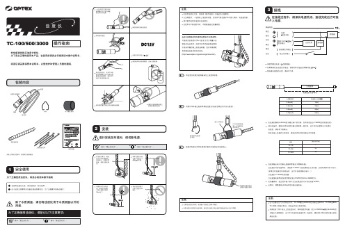
TC-100/500/3000操作指南非常感谢您购买浊度分析仪。
为了安全正确地使用本产品,在使用前请务必仔细阅读本操作说明书。
阅读后请妥善保管本说明书,以便维护和管理人员随时翻阅。
检测仪吊环水平悬挂附件五根电缆扎带操作指南如若元件缺失或损坏,请联系您的销售商。
为了正确使用浊度仪,请务必阅读本操作指南除了水质测量,请勿将浊度仪用于水质测量以外的用途。
将浊度仪电缆的检测器端包上电缆保护套。
用附件吊环通过链条等悬挂浊度仪(链条线等由用户自行提供)。
将吊环穿过链条的末端。
在接线过程中,请保持电源关闭,接线完成后方可接入电源。
棕色蓝色白色黑色绿色红色请使用额定电流≥1A的断路器。
如果需要延长浊度仪的电线,请使用带引线盒的屏蔽导线(CVV-S)想知道电源线的长度,请参考下表电源线的长度X[m]公称截面积电线最大长度X[m]0.2[mm2]0.3[mm2]0.5[mm2]0.75[mm2]10[m]20[m]40[m]50[m]在连接到模拟(4-20mA)信号输出端口的时候,负荷电阻应当<=300Ω(包括电线电阻)清洁设备后,模拟(4-20mA)信号输出将保留一段时间。
由于时间长度取决于浊度仪的类型,请参考下表确认。
但若在接上电源后立即清洗,模拟(4-20mA)信号输出将不保留。
类型TC-100TC-500TC-3000保留时间(秒)16060自检测输出端口的输出是晶体管输出(开路集电极)。
当连接到外部设备等时,请选择+12VDC 与自检测输出之间的值,必要时请参考如下条目。
(如果没有连接到外部设备时,应打开自检测输出端口。
)◎连接到>= 600Ω的电阻器;◎连接继电器等(建议使用额定电压12VDC 的Omron G6B 系列)。
在测量期间,校正信号输入端口应当至拨起的打开状态或接12VDC 。
必要时,调整模拟(4-20mA)信号输出接收端。
调整模拟(4-20mA)信号输出已知浓度的测量水(福尔马肼等)与模拟(4-20mA)信号输出之间可能存在差异。
TC500中文资料
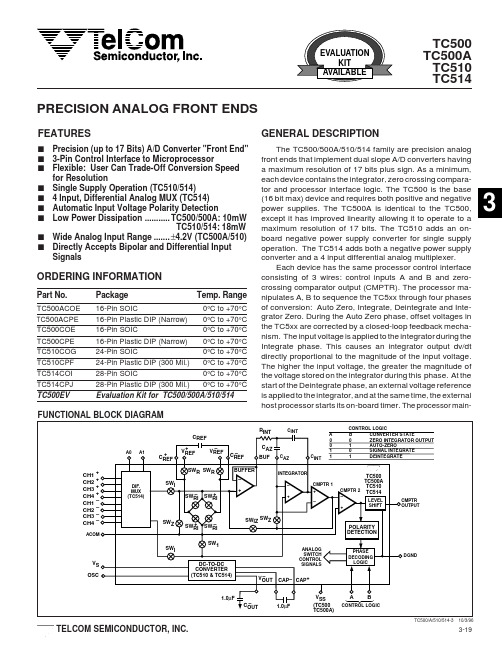
DGND
ORDERING INFORMATION
Part No.
TC500ACOE TC500ACPE TC500COE TC500CPE TC510COG TC510CPF TC514COI TC514CPJ TC500EV
Package
16-Pin SOIC 16-Pin Plastic DIP (Narrow) 16-Pin SOIC 16-Pin Plastic DIP (Narrow) 24-Pin SOIC 24-Pin Plastic DIP (300 Mil.)
塔吊说明书

5010塔吊说明书前言1、首先感谢您购买本公司的塔式起重机,为了帮助您了解塔机安装的性能,安全、快速地安装和正确地使用,以保证工程的顺利完成,请您仔细地阅读本说明书,并按规定的方法操作。
2、塔机第一次安装时,我公司派一名技术人员指导安装,您一定要聘请当地有安装资质的安装队伍安装,并拿我公司提供的资料向当地有关管理部门报检,我公司资料中有一回执单,请您认真填写并提出宝贵意见。
第一次和以后安装时,禁止夜间施工3、本说明书主要阐述最常用的安装形式,凡属下面情况之一者,应及时与我公司联系。
a.塔机基础不能按本说明书规定形式处理;b.塔机安装位置过于狭窄,以至于在拆塔机时,部件与建筑物发生干涉;c.塔机的起升高度超过说明书规定。
4、本公司致力于产品的不断完善,产品的某些局部结构或个别参数更改时,恕不另行通知。
如有疑问,请与本公司联系。
5、建议使用单位应为塔机建立设备档案,档案应包括以下内容:a.每次使用时间及安装地点;b.日常使用保养、维修、变更、检查和试验记录;c.设备故障记录;d.设备存在的问题和评价。
6、客户自选配置(需加价):a.驾驶室的冷、暖空调;b.风速仪;c.无线对讲机;7、三包条件:本公司不承担由以下原因造成的损坏、断裂和事故的任何法律责任: a.塔机零、部件(包括备件、配件)不是由本公司提供的;b.塔机的更换式修理不是由具备修理塔机条件和级别证书的修造单位进行的;c.安装使用、拆卸和维修没有严格遵照使用说明书;及有关法律规定使用的;d.违反了法律制定的安全规则;e.因不可抗拒原因造成的(如:地震、台风、洪水、战争等);8、塔机在使用期间,不得私自调节或拆除、限位安全装置,否则后果自负。
特别提示:在任一安全机构失灵的状态下,严禁使用!!!安全操作规程1、司机应具备的条件:(1)司机应年满18周岁,具初中以上文化程度;(2)不得患有色盲、听觉障碍等病症,视力不得低于1.0;(3)不得患有高血压、贫血、癫痫、突发性昏厥、美尼尔氏综合症等疾病及妨碍操作的生理缺陷等;(4)司机必须经省、市有关部门或其指定单位进行基础理论知识、操作技能、安全技术的培训,考核合格后,持证上岗,严禁无证独立操作。
Thermostat TC500A商品说明书
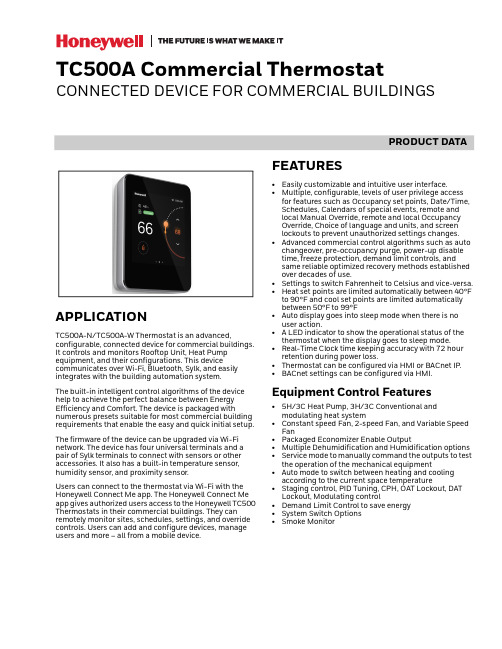
PRODUCT DATATC500A Commercial ThermostatCONNECTED DEVICE FOR COMMERCIAL BUILDINGSAPPLICATIONTC500A-N/TC500A-W Thermostat is an advanced,configurable, connected device for commercial buildings. It controls and monitors Rooftop Unit, Heat Pump equipment, and their configurations. This devicecommunicates over Wi-Fi, Bluetooth, Sylk, and easily integrates with the building automation system.The built-in intelligent control algorithms of the device help to achieve the perfect balance between Energy Efficiency and Comfort. The device is packaged withnumerous presets suitable for most commercial building requirements that enable the easy and quick initial setup.The firmware of the device can be upgraded via Wi-Fi network. The device has four universal terminals and a pair of Sylk terminals to connect with sensors or other accessories. It also has a built-in temperature sensor, humidity sensor, and proximity sensor.Users can connect to the thermostat via Wi-Fi with the Honeywell Connect Me app. The Honeywell Connect Me app gives authorized users access to the Honeywell TC500 Thermostats in their commercial buildings. They can remotely monitor sites, schedules, settings, and override controls. Users can add and configure devices, manage users and more – all from a mobile device.FEATURES•Easily customizable and intuitive user interface.•Multiple, configurable, levels of user privilege access for features such as Occupancy set points, Date/Time, Schedules, Calendars of special events, remote and local Manual Override, remote and local Occupancy Override, Choice of language and units, and screen lockouts to prevent unauthorized settings changes.•Advanced commercial control algorithms such as auto changeover, pre-occupancy purge, power-up disable time, freeze protection, demand limit controls, and same reliable optimized recovery methods established over decades of use.•Settings to switch Fahrenheit to Celsius and vice-versa.•Heat set points are limited automatically between 40°F to 90°F and cool set points are limited automatically between 50°F to 99°F•Auto display goes into sleep mode when there is no user action.• A LED indicator to show the operational status of the thermostat when the display goes to sleep mode.•Real-Time Clock time keeping accuracy with 72 hour retention during power loss.•Thermostat can be configured via HMI or BACnet IP.•BACnet settings can be configured via HMI.Equipment Control Features•5H/3C Heat Pump, 3H/3C Conventional and modulating heat system•Constant speed Fan, 2-speed Fan, and Variable Speed Fan•Packaged Economizer Enable Output•Multiple Dehumidification and Humidification options •Service mode to manually command the outputs to test the operation of the mechanical equipment•Auto mode to switch between heating and cooling according to the current space temperature•Staging control, PID Tuning, CPH, OAT Lockout, DAT Lockout, Modulating control•Demand Limit Control to save energy •System Switch Options •Smoke MonitorTC500A COMMERCIAL THERMOSTAT31-00398M-02 | Rev. 04-212TECHNICAL SPECIFICATIONSPower CharacteristicsDisplayIO CharacteristicsOperating EnvironmentTable 1. Power CharacteristicsPower SupplyRated voltage: 24VAC 50/60Hz,Working voltage range: 20-30VAC, UL listedclass-2 transformer or IEC 61558 listed transformer.Power Consumption (Display ON)Max. 8.5VA @ 24VAC (355mA @ 24VAC)Min. Load 4VA (all DOs OFF, No Sylk sensor)Max. Load96VA (all DOs ON)Table 2. DisplayDisplay Type 24 BPP TFT display with CTPResolutions 480x480 pixel Active Display Area 4” diagonally BacklightLCD (Dimmable)Table 3. IO CharacteristicsUIO x 2•Resistive Temperature Sensor Input—10K NTC type II, C7021 series —10K NTC type III,C7023 series —20K NTC, TR21 and C7041series.•Temperature Accuracy—±0.5°C (±1°F) at 10 – 32°C (50– 90°F)—±1.1°C (±2°F) at -1.1 – 50°C(30 – 122°F)•Voltage Input, SELV—0-10V, ±5% of full scale •Digital Input—Dry contact closure—Open circuit (≥ 100Kohms)—Closed circuit (≤100ohms)•Voltage Output—0-10V, ±3% of full scale @2KohmsUI x 2•Resistive Temperature Sensor Input—10K NTC type II, C7021 series —10K NTC type III,C7023 series —20K NTC, TR21 and C7041series•Temperature Accuracy—±0.5°C (±1°F) at 10 – 32°C (50– 90°F)—±1.1°C (±2°F) at -1.1 – 50°C(30 – 122°F)•Voltage Input, SELV—0-10V, ±5% of full scale •Digital Input—Dry contact closure—Open circuit (≥ 100Kohms)—Closed circuit (≤100ohms)DO (G,Y1,Y2,Y3,W1,W2,W3)•Relay Output— 1 Amps Max. at 24VAC DO (AUX)•Relay Dry Contact— 1 Amps Max. at 24VAC/DCTable 4. Operating EnvironmentAmbient Operating Temperature 32 to 122 °F (0 to +50°C)Ambient Operating Humidity 10 to 90% relative humidity (non-condensing)StorageTemperature -40 to 150 °F(-40 to 65.5°C)Protection ClassIP20Table 3. IO Characteristics (Continued)TC500A COMMERCIAL THERMOSTAT331-00398M-02 | Rev. 04-21CompliancesCommunication TechnologiesElectrical CharacteristicsSupported Sensors and FunctionsTable 5. CompliancesCertificates CE, FCC, ICES, UL/cUL, RoHs, REACH, California, Title 24, and Prop65.StandardsEN 60730-1, EN 60730-2-9, EN 301489-1, EN 301489-17, EN 300328, EN 301893, EN 62479, UL60730-1, UL60730-2-9, Title 47 part 15 subpart B, Title 47 part 15 subpart C, RSS 210, ICES-003Table 6. Communication TechnologiesBACnet IP Over Wi-FiWi-Fi802.11 b/g/nSupported security levels WPA,WPA3_WAP2_AES, WAP2_FBT_ENT, WPA2, WPA_ENT,WPA2_FBT, and WPA2_ENTBluetoothBLE 4.2 with 1 Mbps Classic Bluetooth with max. 3 Mbps Sylk TMHoneywell Sylk TMTable 7. Electrical CharacteristicsRated Impulse Voltage 500 VConstruction of Control Independently Mounted Control Operation Method Type 1 Action Pollution Degree 2Purpose of ControlOperating ControlTable 8. Supported Sensors and Functions Sensors Options Part Numbers Occupancy SensorDirect(Normally Open)Reverse (Normally Closed)Dry contactoccupancy sensorDirty Filter SensorDirect(Normally Open)Reverse (Normally Closed)DPS200, DPS400, DPS1000(Dry contact differentialpressure switch)Proof Of Air Flow SensorDirect(Normally Open)Reverse (Normally Closed)DPS200, DPS400, DPS1000(Dry contact airflow switch)Shutdown SensorDirect(Normally Open)Reverse (Normally Closed)Dry contactshutdown switchMixed Air Temperature Sensor NTC 20K, Type II NTC 10K, Type II SylkC7250C7021C7400S Outdoor Air Temperature Sensor NTC 20K, Type II NTC 10K, Type II Sylk C7250A C7021C7400S Return Air Temperature Sensor SylkC7400SDischarge Air Temperature Sensor NTC 20K, Type II NTC 10K, Type II SylkC7041C7021C7400SSpaceTemperature Sensors NTC 20K, Type II SylkTR21TR40/TR75 (max 4), TR120 (max 1)Fan Current Sensor Max Amps 0~<+Inf AmpsComing soonCO2 sensor (analog)0-10 VDC or Sylk Sylk C7232TR40-CO2, TR42-CO2Proof of waterflowDigital InputDry contactwaterflow switchTC500A COMMERCIAL THERMOSTAT31-00398M-02 | Rev. 04-214Terminal IdentificationFig. 1. TerminalsThermostat VariantsAccessoriesTable 9. Terminal IdentificationTerminalLabelConnection24VACR24VAC power from heating transformerC24VAC common (Neutral). For 2 transformer systems, use common wire from cooling transformerUIO11Universal input/output COM CommonUIO22Universal input/output COM Common UI11Universal input COM Common UI22Universal input COMCommonSylk (S-BUS)Sylk bus, master, power output Sylk bus, master, power outputRS485+BACnet Communications (coming soon)_BACnet Communications (coming soon)R-RCJumper between R and RC for single transformer system24VACRC 24VAC power from cooling transformer G FanY1Relay output, Compressor contactor (stage1)Y2Relay output, Compressor contactor (stage2)Y3Relay output, Compressorcontactor (stage3)/Configurable OutputW1Relay output, Heat (stage1)W2Relay output, Heat (stage2)W3Relay output, heat(stage3)/Configurable Output AuxRelay dry contact, Aux-1Relay dry contact, Aux-2Table 10. Thermostat Part NumbersTC500A-NThermostat with North American Wi-Fi conformanceTC500A-W (coming soon)Thermostat with outside of North American Wi-Fi conformanceTable 11. Accessories Part NumbersDecoplate-N TC500 deco plate for NA junction boxes Decoplate-WTC500 deco plate for Globe junction boxesTable 9. Terminal Identification TerminalLabel ConnectionTC500A COMMERCIAL THERMOSTAT531-00398M-02 | Rev. 04-21Terminal AssignmentsNOTE:*Marked sensors are supported in the future.Table 12. Terminal AssignmentsType Terminal LabelTerminal Assignments(Default & Optional Assignments)DEFAULTINPUTSOUTPUTSDigital OutputsDO1G Supply Fan High Speed FanDO2W1Heat Stage 1DO3W2Heat Stage 2DO4W3 / AuxHeat Stage 3Reversing Valve OB, Low Speed Fan,Occupancy, Simple Dehum, and Humidification.DO5Y1Cool Stage 1DO6Y2Cool Stage 2DO7Y3 / AuxCool Stage 3Economizer (Enable), Low Speed Fan,Occupancy, Simple Dehum, and Humidification.DO8(Dry Contact, 2 terminals)AuxEconomizer (Enable), Occupancy,Simple Dehum, Low Speed Fan, and Humidification.Universal InputsUI1(2 terminals)UI1NA Occupancy Sensor,Dirty Filter,Proof of Airflow,Shutdown Sensor,Mixed Air Sensor,Outdoor Air Sensor,Discharge Air Sensor,CO2 Sensor,Proof of Waterflow,Space Temp Sensor,*Filter Pressure sensor,*Compressor Current Sensor,*Fan Current Sensor,*Compressor Discharge, *Temperature sensor UI2(2 terminals)UI2NA Universal Inputs/ OutputsUIO1(2 terminals)UIO1NA Multi-Speed Fan (UIO1) Outdoor Air Damper UIO2(2 terminals)UIO2NAModulating Heat (UIO2) Outdoor Air DamperPowerRR 24v Power C C CommonRCRC 24v Power / Cooling Sylk Bus1S-BusSylk connection2TC500A COMMERCIAL THERMOSTAT31-00398M-02 | Rev. 04-216DIMENSIONS3 - 1/4” (82.75mm)TC500A COMMERCIAL THERMOSTAT731-00398M-02 | Rev. 04-21GENERAL SAFETY INFORMATION•When performing any work (installation, mounting, start-up), all manufacturer instructions and in particular the mounting Instructions guide (31-00399M) and the user guide (31-00400M) are to be observed.•TC500A-N/TC500A-W Thermostat may be installed and mounted only by authorized and trained personnel.•Rules regarding electrostatic discharge should be followed.•If TC500A-N/TC500A-W Thermostat is modified in any way, except by the manufacturer, all warranties concerning operation and safety are invalidated.•Make sure that the local standards and regulations are observed at all times.•Use only accessory equipment which comes from or has been approved by Honeywell.•It is recommended that devices be kept at roomtemperature for at least 24 hours before applying power. This is to allow any condensation resulting from low shipping/storage temperatures to evaporate.•Investigated according to United States Standard UL-60730-1, and UL60730-2-9.•Investigated according to Canadian National Standard(s) C22.2, No. 205-M1983 (CNL-listed).•Do not open TC500A-N/TC500A-W Thermostat, as it contains no user-serviceable parts inside!•CE declarations according to LVD Directive 2014/35/EU and EMC Directive 2014/30/EU.•Product standards are EN 60730-1 and EN 60730-2-9.•TC500A-N/TC500A-W Thermostat is Class B digital apparatus and complies with Canadian ICES-003.•This device complies with part 15 of the FCC Rules. Operation is subject to the following two conditions: (1) This device may not cause harmful interference, and (2) this device must accept any interference received, including interference that may cause undesired operation.•Caution: Changes or modifications to this unit not expressly approved by the party responsible forcompliance could void the user's authority to operate the equipment.•This device contains licence-exempttransmitter(s)/receiver(s) that comply with Innovation, Science and Economic Development Canada’s licence-exempt RSS(s). Operation is subject to the following two conditions:1.This device may not cause interference.2.This device must accept any interference, includinginterference that may cause undesired operation of the device.•L’émetteur/récepteur exempt de licence contenu dans le présent appareil est conforme aux CNR d’Innovation, Sciences et Développement économique Canada applicables aux appareils radio exempts de licence. L’exploitation est autorisée aux deux conditions suivantes:1.L’appareil ne doit pas produire de brouillage;2.L’appareil doit accepter tout brouillage radioélec -trique subi, même si le brouillage est susceptible d’en compromettre le fonctionnement.•This equipment has been tested and found to comply with the limits for a Class B digital device, pursuant to part 15 of the FCC Rules. These limits are designed to provide reasonable protection against harmfulinterference in a residential installation. This equipment generates uses and can radiate radio frequency energy and, if not installed and used in accordance with the instructions, may cause harmful interference to radio communications. However, there is no guarantee that interference will not occur in a particular installation. If this equipment does cause harmful interference to radio or television reception, which can be determined by turning the equipment off and on, the user isencouraged to try to correct the interference by one or more of the following measures:—Reorient or relocate the receiving antenna.—Increase the separation between the equipmentand receiver.—Connect the equipment into an outlet on a circuitdifferent from that to which the receiver is con -nected.—Consult the dealer or an experienced radio/TV tech -nician for help.•To satisfy FCC&IC RF exposure requirements, a separation distance of 20 cm or more should be maintained between the antenna of this device andpersons during device operation. To ensure compliance, operations at closer than this distance is not recommended.•Les antennes installées doivent être situées de facon à ce que la population ne puisse y être exposée à une distance de moin de 20 cm. Installer les antennes de facon à ce que le personnel ne puisse approcher à 20 cm ou moins de la position centrale de l’ antenne. Region Selection (for Wi-Fi 2.4G device)•Limited by local law regulations, version for North America does not have region selection option.Safety Information as per EN60730-1TC500A-N/TC500A-W Thermostat is intended for residential, commercial environments.TC500A-N/TC500A-W Thermostat is an independently mounted electronic control system with fixed wiring.TC500A-N/TC500A-W Thermostat is used for the purpose of building HVAC control and is suitable for use only in non-safety controls for installation on or in appliances.NoteAll images used in this document are for illustrative purposes only and may not match the actual product.TC500A COMMERCIAL THERMOSTAT® U.S. Registered Trademark© 2021 Honeywell International Inc.31-00398M-02 | Rev. 04-21Honeywell Building TechnologiesHoneywell715 Peachtree Street NE Atlanta, GA 。
TC500EP采暖温控器说明书(英文柯耐弗)1
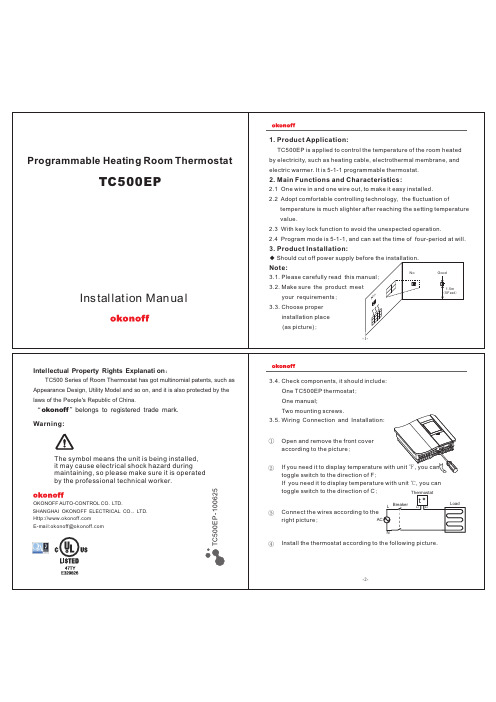
4. Technical Parameter:
Power Supply: Temperature Control Range: Temperature Display Range: Standard Load: Sensing Element: Temperature Control Precision: 120/208/220/240VAC, 50/60HZ + 5℃~+ 3 0℃ (4 0℉~ 9 0℉) 0℃~+ 6 0℃ (32℉~ 14 0℉) Max: 16A, Min: 3A NTC
P1
-3-
-5-
5. Interface and Operational Instruction:
Set Mode Press “SET” key to enter into the time setting state, and it will display the interface as picture. SET At this time, press “Up” or “Down” key to set the current time. Press one time, it will increase or decrease 1 min. If you press “Up” or “Down” key continually, the setting time will be fast increased or decreased by10 min. Then press “SET” key to set the week, and it will display the interface as picture
Warning:
①
Open and remove the front cover according to the picture; If you need it to display temperature with unit ℉, you can toggle switch to the direction of F; If you need it to display temperature with unit ℃, you can toggle switch to the direction of C; Thermostat
Phoenix Audio Pivot-TC 500 音频控制器说明书
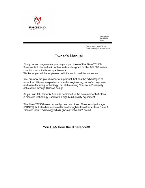
Costa MesaCA 92626USATelephone +1 866 302 1091Email:**********************Owner’s ManualFirstly, let us congratulate you on your purchase of the Pivot-TC/500 Tone control channel strip with equalizer designed for the API 500 series Lunchbox or suitable compatible rack.We know you will be as pleased with it’s sonic qualities as we are.You are now the proud owner of a product that has the advantages of more than 40 years experience in audio engineering, today’s component and manufacturing technology, but still retaining “that sound” uniquely achievable through Class A design.As you can tell, Phoenix Audio is dedicated to the development of ClassA discrete technology used within high build-quality equipment.The Pivot-TC/500 uses our well proven and loved Class A output stage (DSOP2), but also has our latest breakthrough in transformer-less Class A, Discrete Input Technology which gives a "valve-like" sound.You CAN hear the differenceDescription:The Tilt Eq concept was first developed in the 1970's by Quad Ltd, it first appeared on the company’s model 34 preamplifier. The tilt control tilts the frequency content of the audio signal by simultaneously boosting the treble and cutting the bass frequencies, or vice versa, making it a simple to use but powerful EQ.Phoenix Audio have re-imagined this and taken the original concept and extended it to provide 3 unique selectable pivot points around which the audio can be tilted.Pivot-TC/500 SpecificationsAPI 500 series compatible rack unit:Class A (DSOP2) Output specs.Frequency response: 20Hz to 20k +/ - 0.5dB.Maximum Output = +26dBu @ 1kHzNoise = -90dB @ 20Hz to 20kHz.Phoenix Audio’s unique Class A, transformer-less, True electronically balanced input stage.Typical Headroom: +26dB on output stageInput connections: XLR input on rear of API compatible rack and TS 1/4"Jack on front for DI input & TS through input.Output connections: XLR output on rear of API compatible rackHigh Input Impedance DI: Mono 1/4" Jack on front panelDI Stage gain: Maximum of 30dB gain rangeGain Meter: LED output Metering. (Green = -4dbu, to +10dBu in 2db increments, Yellow = +12dbu Red= +14dBu)Pivot ‘Tilt style’ EQ controls : Rotary switch with 3 pivot points : Bypass, 160hz, 800hz & 1.6khz.Toggle Switch : Allowing Line level mode or DI modeDark/bright control : Rotary control allowing the degree of tilt on each frequency, more dark control will boost LF and reduce HF and more bright control will boost HF and reduce LFOutput Level : An output fader which will allows you to control the output level. Power requirements: The Pivot-TC/500 utilizes the rack's +16V and -16V power rails, but uses our unique on-board power supply to convert the rails to +24V and 0V so that the unit sounds exactly the same as our mains-powered 19” units. This means you always know that the Phoenix sound is consistent across our whole range of products..Pivot-TC/500 SETUP INSTRUCTIONSThe Pivot-TC/500 has a vertical row of LED’s to indicate output level. These LED’s are connected to the OUTPUT of the unit, NOT the input section. This makes the LED’s indication much more useful for setting up levels on the Tilt Tone channel and will give you a clearer view of what level is being sent to external equipment.The LED metering has 2 selectable modes. Dot and Bar modes. The mode is selected by the LK1 (Red) jumper link on the upper (small) circuit board. No link =BAR mode. Placing a shorting link (fitted as standard) onto LK1 will put the LED metering into DOT mode.The LED’s are marked –4 to +10 (Green) and +12 (Yellow) and +14 (Red).When the Red Led lights, this isn’t a sign of clipping as the Pivot TC will have at least another 12db of headroom.You can turn the output knob all the way up to maximum and still be sure the outputof the unit will not clip. The amount of headroom on both the input AND output stageis HUGE There will never be a time when you can't get a hot enough output, only occasionally too hot an input (then you just simply turn down the input signal coming into your Pivot TC.When using the DI input, plug the external signal source into the 1/4” jack on the front panel, and adjust the OUTPUT Level so that the 0dB Green Led is just illuminated. This will give an output Level of 0dB and can be adjusted to taste.The OUTPUT level knob is provided to allow OUTPUT level adjustment. If you preferto have a “hotter” output, turn the OUTPUT knob up to suit. You can turn theOUTPUT knob fully up without any distortion, as there is plenty of headroom on the output stage. Also, if you prefer to have a LOWER level on the output (I.E.: for semi-pro outboard gear which requires around -10dB input), simply turn the OUTPUT knob down to taste. The combination of the Class A discrete output stage coupled with our custom wound transformer will impart second harmonics into your music and also a form of compression, similar to tape compression, this will be achieved by runningthe unit with a high output level.to 20hz frequency spectrum. Each pivot point is shown – 160hz, 800hz and 1.6khz.Here is a description of the Pivot TC/500’s front panel, showing all the connections and controls available.。
TC500A商务温度仪式装置安装说明书

MOUNTING INSTRUCTIONSTC500A Commercial ThermostatCONNECTED DEVICE FOR COMMERCIAL BUILDINGSINTRODUCTIONTC500A Commercial Touchscreen Thermostat is designed to be wall-mounted indoors. Mount in a clean, dry location away from windows, air ducts, and other places where environmental factors may affect temperature and humidity readings. If you mount the Thermostat on the interior of an outside wall, thoroughly insulate so outside air behind the sensor does not affect the sensor reading. To meet the requirements of the Americans withDisabilities Act, mount no higher than 48" from the floor and with a minimum clear floor space of 30" X 48" (760 X 1220 mm).Supported Documents•TC500A-N Commercial Thermostat Datasheet (31-00398M)•TC500A-N Commercial Thermostat User guide (31-00400M)•TC500A-N Commercial Thermostat Quick start guide (31-00401M)•TC500A-N Commercial Thermostat Pocket guide (31-00463M)•TC500A Deco Plate Pocket guide (31-00457M)When installing this product1.Read these instructions carefully. Failure to followthem could damage the product or cause a hazard -ous condition.2.Check the ratings given in the instructions andmarked on the product to make sure the product is suitable for your application.3.Installer must be a trained, experienced service tech -nician.4.After installation is complete, check the productoperation.5.Be sure wiring complies with all applicable codes,ordinances and regulations.WARNINGElectrical Shock Hazard.Can cause severe injury, death or property damage. Disconnect the power supply before beginning installation to prevent electrical shock andequipment damage. More than one power supply may have to be disconnected.MERCURY NOTICEIf this control is replacing a control that contains mercury in a sealed tube, do not place your old control in the trash. Dispose of properly. Contact your local waste management authority forinstructions regarding recycling and the proper disposal of an old control. If you have questions, contact Honeywell Customer Care Center.LocationDo not install the Thermostat unit where it can be affected by:—drafts or dead spots behind doors and in corners.—hot or cold air from ducts.—radiant heat from sun or appliances.—concealed pipes and chimneys.—unheated (uncooled) areas such as an outside wall behind the thermostat.IMPORTANTTo avoid electrical interference, which can cause erratic performances, keep wiring runs as short as possible and do not run thermostat wires adja -cent to the line voltage electrical distribution sys -tems. Use shielded cable. The cable shield must be grounded only at the controlled equipment case.WHEN USED TO SENSE ROOM TEMPERATUREInstall the Thermostat about 4 ft. (1.2m) above the floor in an area with good air circulation at average temperature. (See Fig. 1). Confirm mounting height meets Americans with Disabilities Act requirements.TC500A-N/TC500A-W COMMERCIAL THERMOSTAT 31-00399M-02 | Rev.03-212WHEN NOT USED TO SENSE ROOM TEMPERATURE When using the remote-mounted temperature (and humidity) sensor(s) to sense ambient conditions, install the Thermostat in an area that is accessible for setting and adjusting the temperature and settings.Fig. 1. Typical mounting location of thermostatThis symbol on our product shows a crossed-out “wheelie-bin” as required by law regarding the Waste ofElectrical and Electronic Equipment (WEEE) disposal. This indicates your responsibility to contribute in savingthe environment by proper disposal of this Waste i.e. Do not dispose of this product with your other wastes. To know the right disposal mechanism please check the applicable law.Regulation (EC) No 1907/2006According to Article 33 of Reach Regulation be informed that the substances listed below may be contained in these products above the threshold level of 0.1% by weight of the listed article.Power supply guidelines and requirementsThe thermostat uses 24VAC power from a UL Listed Class-2 24VAC transformer (not provided in the kit). It also uses a half-wave rectifier to convert the AC power supply to onboard power. This enables multiple devices with half-wave power supplies to be powered from a single, grounded transformer.WARNINGHalf wave devices and full wave devices must not use the same AC transformer.You must maintain wiring polarity. Failure to do so can result in equipment damage. If the HVAC equipment has an internal circuit board that is powered by the same transformer that will power the Thermostat, verify that it is NOT full wave.Fig. 2. Power terminalsPower supply wire sizingLong power supply wiring runs require selecting the wire gauge appropriately. If the wire gauge is inadequate the increased resistance and associated voltage drop mayresult in insufficient voltage supply to the Thermostat. The recommended wire gauge guidelines are as follows.Min. Load = 4VA (all DOs OFF, No Sylk sensor).If 18-20AWG wire is used for R, C, RC terminal,Max. Load = 4A, 96VA (all DOs ON). If 22AWG wire is used for R, C, RC terminal Max. Load = 3A, 72VA (all DOs ON).If R-Rc power jumper is not removed, then G, W1, W2, W3, Y1, Y2, Y3 are powered from the Thermostat’s transformer. Minimum load includes Thermostat and analog outputs at full load (Max. 10V voltage output with 2Kohms load).Every relay output is N.O. (Normally Open) contacts with a maximum switch rating of 24VAC @1A (24VA). The allowed maximum load is 96VA, which assumes all 8 relay output loads are powered from the controller transformer. Actual power requirements depend on connected loads.IMPORTANTTransformer sizing should never exceed the maxi -mum UL Class 2 rating.The 24VAC secondary leads are not interchangeable . Once a lead connects to the GND terminal, it is the grounded lead. Observe and maintain polarity forsubsequent connections. The GND terminal provides a reference ground for the circuit board andcommunications wiring. Use 18 AWG cable for best results.WEEEWEEE (Waste of Electrical andElectronic Equipment)•At the end of the product life, dispose of the packaging andproduct in an appropriate recycling center.•Do not dispose of the device with the usual domestic refuse.•Do not burn the device.Product/Part CodeSubstance NameCAS Number Only TC500A thermostat mainboard PCBA, thermostat wall plate board PCBALead 7439-92-1Lead oxide 1317-36-8+ DC VoltageGND24VACRCTC500A-N/TC500A-W COMMERCIAL THERMOSTAT331-00399M-02 | Rev.03-21WARNINGEnsure that all Thermostat power, communications, and I/O cabling are connected to C or COM according to these instructions. Failure to follow these instructions may result in Thermostat operational and communication failures or equipment damage.Detaching the wallplate from the displayThe thermostat is an assembly of a wallplate and a display. It must be disassembled before starting the mounting procedure.1.At bottom of the thermostat, loosen the Securityscrew using a screwdriver by turning it counter-clockwise direction.2.Hold the display unit and pull the paper tail.Fig. 3. Detaching the wallplateMounting wallplate on the drywallMount the wallplate vertically on the wall. It supports 18-22 AWG (0.5-0.75mm2) wires.NOTE:If you are using a TC500A Deco plate for thermo -stat mounting, refer to the Deco plate pocket guide (31-00457M) also.1.Before mounting the wallplate, make sure that thethermostat wires are stripped to the length marked on the wallplate.Fig. 4. Wire strip length2.Position and level the wallplate along the wall and mark the drilling location using a pencil.Fig. 5. Wallplate drilling locations3.Remove the wallplate and drill two pilot holes on the wall, on the marks. For drywall, drill 3/16-in. holes. For firmer material such as plaster, drill 7/32-in. holes.4.Gently tap anchors (provided in the kit) into the pilot holes until flush with the wall.5.Pull the wires through the wiring opening of the wall -plate and position the wallplate over the mounting holes.6.Insert the screws into the holes and tighten (screw torque 0.1Nm).Mounting the wallplate on the junction box (optional)The thermostat wallplate can be mounted vertically on a US 2”*4” or UK 75*75mm junction box.NOTE:If you are using other than US 2”*4” or UK75*75mm junction boxes, then a TC500A Deco plate can be used for thermostat mounting. Refer to the Deco plate pocket guide (31-00457M).1.Install the junction box and perform the wiring as per its manufacturer’s instruction.2.Before mounting the wallplate, make sure that the thermostat wires are stripped to the length marked on the wallplate.3.Pull the wires through the wiring opening of the wall -plate, and position the wallplate along the junction box to align the mounting holes. For junction box screw holes, refer to Fig. 5.4.Insert the screws into the holes and tighten.Paper tail4 x 11/32”2 - 3/8” (60.3mm)(UK 75X75cm junction box3 - 1/4” (82.75mm)(US 2”X4” junctionTC500A-N/TC500A-W COMMERCIAL THERMOSTAT31-00399M-02 | Rev.03-214Accessories ordering part numbersTerminal identificationFig. 6. Thermostat terminal assignmentsWARNINGDo NOT wire the thermostat to line voltage.IMPORTANTRemove R to RC jumper only for 2 transformer sys -temsTable 1. Accessories Part NumbersDecoplate-N TC500 deco plate for NA junction boxes Decoplate-WTC500 deco plate for Global junction boxesTable 2. Terminal identificationTerminalLabel Connection24VACR24VAC power from heating Class 2 transformerC24VAC common (Neutral). For 2 transformer systems, usecommon wire from the cooling transformerUIO11Universal input/output COMCommonUIO22Universal input/outputCOM Common UI11Universal input COM Common UI22Universal input COMCommonSylkSylk bus, master, power outputSylk bus, master, power outputRS485+BACnet Communications (coming soon)_BACnet Communications (coming soon)R-RCJumper between R and RC for single transformer system, remove the jumper in two transformer system.24VACRC 24VAC power from cooling Class 2 transformer G FanY1Relay output, Compressor contactor (stage1)Y2Relay output, Compressor contactor (stage2)Y3Relay output, Compressorcontactor (stage3)/Configurable OutputW1Relay output, Heat (stage1)W2Relay output, Heat (stage2)W3Relay output, Heat(stage3)/Configurable Output AuxRelay dry contact, Aux-1Relay dry contact, Aux-2Table 2. Terminal identification (Continued)TerminalLabel ConnectionTC500A-N/TC500A-W COMMERCIAL THERMOSTAT531-00399M-02 | Rev.03-21Wiring the wallplateIMPORTANTAll wiring must comply with local electrical codes and ordinances.NOTE:Supports 18-22 AWG (0.5-0.75mm 2). Solid wire isrecommended.Follow equipment manufacturer wiring instructions when available. A letter code is located near each terminal foridentification.Wiring a unit that is powered may result in electrical shock and/or equipment damage.1.Connect wires to the terminals. See Fig. 6 for terminalassignments and Table 1 for terminal descriptions.2.Insert the solid wire into the terminal hole directly.3.(optional) To insert stranded wire end into the wiringterminal, push the Release tool into the Tool hole and insert the wires.Fig. 7. Wire release4.Push excess wire back into the hole.5.Check for the loose or frayed wire that may cause ashort.Mounting the display unitAfter all wiring is completed, install the display onto the wallplate.1.Hold the display in a tilted position so the latches fit onto the rectangular slots of the wall plate as shown in the below image.2.Insert the latches onto the wallplate rectangular slots and rotate the display and push it onto wallplate.3.by turning it in the clockwise direction (screw torque0.1Nm).TC500A-N/TC500A-W COMMERCIAL THERMOSTAT® U.S. Registered Trademark© 2021 Honeywell International Inc.31-00399M-02 | Rev.03-21Honeywell Building TechnologiesHoneywell715 Peachtree Street NE Atlanta, GA DIMENSIONS(60.3mm)3 - 1/4” (82.75mm)。
