DTS6401
CH-DS-6401HFH
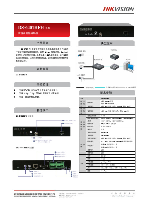
型号 DS-6401HFH视音频输入视频输入 1路,HD-SDI 接口 1路,OPT 光传输接口音频输入 1路,RCA 接口(电平:2.0Vp-p,阻抗:1KΩ) 视音频输出音频输出 1路,RCA 接口(线性电平,阻抗:600Ω) 视音频编码参数视频压缩标准H.264视频编码分辨率/帧率 1920*1080@50i,1920*1080@60i,1920*1080@25p,1920*1080@30p,1600*1200@25fps 视频码率 2Mbps-16Mbps 可自定义 码流类型 复合流/视频流 双码流 支持 音频压缩标准 OggVorbis 音频码率16K/32Kbps外部接口语音对讲输入 1路,RCA 接口(电平:2.0Vp-p,阻抗:1KΩ) 网络接口1个,RJ45 10M/100M/1000Mbps 自适应以太网口 串行接口 标准485串行接口,1个 标准232串行接口,1个 报警输入4路 报警输出 2路 其他电源 DC 12V 功耗≤12W 工作温度 -10℃--+55℃ 工作湿度 10%~90%,无冷凝尺寸198mm(宽) ×123mm(深) ×39mm(高) 重量≤1.5kgDS-6401HFH 系列高清视音频编码器DS-6401HFH 高清视音频编码器是海康威视基于TI 最新平台开发的视音频编码器,采用Linux 操作系统,Davinci处理器,运行稳定可靠。
采用标准H.264压缩算法,支持200W 高清实时编码,支持多种网络协议,为高清网络监控提供强有力的支持。
产品简介DS-6401HFH 功能特性● 支持HD-SDI 接口/OPT 光传输接口视频输入; ● 支持1080p 、720p 、UXGA 等高清分辨率编码; ●支持一键恢复默认配置。
订货型号DS-6401HFH 前面板典型应用物理接口技术参数DS-6401HFH 后面板1324PWR LINK RX/TX 电源、网络、网传,设备状态指示灯音频输入HD-SDI 视频输入接口OPT 光传输接口134658927RESET 复位按钮语音对讲输入音频输出报警输入报警输出电源输入接地端LAN 以太网接口RS-485串行接口RS-232串行接口。
MCH6401中文资料

[MCH6401]
0.25
0.3 0.15
Low ON-resistance. Ultrahigh-speed switching. 2.5V drive.
6
5
4
1.6 2.1
1
0.25
2 3 0.65
2.0
Absolute Maximum Ratings at Ta=25°C
40
20
0 --60
--40
--20
0
20
40
60
25° -C 25°C
V
Ta= 7
5°C
4.0V S=
80
100
120
140
160
Gate-to-Source Voltage, VGS -- V
IT02607
Ambient Temperature, Ta -- °C
IT02608
No.6779-2/4
3.5V
6
ID -- VGS
VDS=10V
3.0V 2.5V
V
Drain Current, ID -- A
5
Drain Current, ID -- A
4.0V
2.0
4
6.0V
VGS=1.5V
3
2
1
0 0.4 0.5 0.6 0.7 0.8 0.9 1.0 0 0.5 1.0 1.5 2.0 2.5 IT02606
Mounted on a ceramic board (900mm2!0.8mm)
Electrical Characteristics at Ta=25°C
Parameter Drain-to-Source Breakdown Voltage Zero-Gate Voltage Drain Current Gate-to-Source Leakage Current Cutoff Voltage Forward Transfer Admittance Static Drain-to-Source On-State Resistance Input Capacitance Output Capacitance Reverse Transfer Capacitance Symbol V(BR)DSS IDSS IGSS VGS(off) yfs RDS(on)1 RDS(on)2 Ciss Coss Crss Conditions ID=1mA, VGS=0 VDS=20V, VGS=0 VGS=± 8V, VDS=0 VDS=10V, ID=1mA VDS=10V, ID=2A ID=2A, VGS=4V ID=1A, VGS=2.5V VDS=10V, f=1MHz VDS=10V, f=1MHz VDS=10V, f=1MHz Ratings min 20 1 ±10 0.4 4.3 6.2 45 60 370 120 80 59 84 1.3 typ max Unit V µA µA V S mΩ mΩ pF pF pF
感温光纤用户手册

DTSCM用户手册v2.1.91.版本更新日志目录1.版本更新日志 (1)2.DTS系列产品介绍 (6)3. DTS系列产品安全说明 (7)3.1通用安全说明 (7)3.2激光安全说明 (8)3.2.1激光分级 (8)4. DTSCM-分布式温度传感器配臵和监控软件 (9)4.1访问级别 (9)4.2系统要求 (9)4.3 安装卸载DTSCM软件 (10)4.4 首次运行DTSCM软件 (10)4.5 菜单栏 (11)4.5.1 项目 (12)4.5.2 配臵 (12)4.5.3 操作 (14)4.5.4 监控 (15)4.5.5 通道选择 (15)4.5.6数据和信息显示 (16)4.5.7 标记 (16)4.5.8 显示选择 (16)4.5.9 安全指示灯 (16)4.5.10 操作 (17)4.5.11 状态 (17)4.5.12 状态栏 (17)4.5.13 曲线区间定位 (18)5.通信配臵 (19)5.1 DTS与PC机的连接 (19)5.1.1 串口连接 (19)5.1.2 网络连接 (21)5.2 多台DTS与PC机的连接 (23)5.2.1 修改DTS的IP、MAC地址 (24)5.2.2 初始化 (24)5.2.3通信配臵 (25)6.校准 (26)6.1校准顺序总览 (26)6.2 采集校准数据 (27)6.3 长度校准 (29)6.3.1 长度校准的原理 (29)6.3.2 长度校准的方法 (30)6.4 温度斜率校准 (30)6.4.1温度斜率校准的原理 (31)6.4.2温度斜率校准的方法 (31)6.4.2.1固定值校准 (31)6.4.2.2匹配校准 (32)6.5 温度偏移校准 (32)6.6 增益校准 (33)6.7 其它校准方法 (33)6.7.1用两个区域校准温度斜率 (34)6.7.2用一个区域校准温度偏移 (35)6.7.3用两个区域校准斜率和偏移 (35)6.8 参数更新 (35)7.用户参数配臵 (37)7.1 高级用户选项 (38)8.报警 (40)8.1报警设臵 (40)8.1.1光纤破坏报警 (41)8.1.2报警索引 (42)8.1.3区域报警设臵 (43)8.2 分区详情 (44)8.3 报警复位 (46)8.4报警和自检 (46)8.5 报警事件查看 (46)9.开始测量 (48)9.1 报警事件 (49)9.2 查看多通道温度数据 (50)10.显示和图形处理 (51)10.1 显示的选择 (51)10.2 图形处理 (51)10.2.1 动态局部窗口 (52)10.2.2 静态局部窗口 (52)10.2.3垂直面区域 (53)10.2.4水平面区域 (53)11.数据管理 (55)11.1温度和原始数据的位臵 (55)11.2报警信息的位臵 (56)11.3最新数据 (56)11.4数据保存选项 (57)11.5查看历史数据 (58)12.配臵流程图 (59)13.一般问题解决 (60)14.联系 (61)2.DTS系列产品介绍DTS系列产品为本公司新开发的模块化分布式光纤温度传感器,该产品可以安装在标准19英寸机架内,并具有标准的通信接口提供给客户以实现温度的实时监测和报警。
SST38LF6401RT 4M ×16 CMOS Advanced Multi-Purpose F

SummaryThe SST38LF6401RT is a 4M ×16 CMOS Advanced Multi-Purpose Flash Plus (Advanced MPF+) upgraded for space applications. It is manufactured with SST proprietary, high-performance CMOS SuperFlash ® technology. The split-gate cell design and thick-oxide tunneling injector attain better reliability and manufacturability compared with alternate approaches. The SST38L-F6401RT writes (program or erase) with a 3.0V to 3.6V power supply. This device conforms to JEDEC standard pin assignments for ×16 memories.SST38LF6401RT Parallel Rad Tolerant Flash MemoryFeatures• Density: 64 Mbit• Read access time: 90 ns • Page size (bytes): 8• Temperature range: –55°C to +125°C • Endurance: 10,000 cycles • Organized as 4M ×16• Single voltage read and write operations : 3.0V to 3.6V • Superior reliability, endurance: up to 10,000 cycles mini-mum, greater than 100 years data retention•Low-power consumption (typical values at 5 MHz)• Active current: 4 mA (typical)• Standby current: 3 µA (typical)• Auto low-power mode: 3 µA (typical)• 128-bit unique ID• Security-ID feature, 256 word, user one-time programmable• Protection and security features, hardware boot block protection/WP# input• Hardware Reset Pin (RST#)•Fast read and page read access times: 90 ns page read access times, 4-word page read buffer• Latched address and data• Fast erase times: sector-erase time: 18 ms (typical), block-erase time: 18 ms (typical), chip-erase time: 40 ms (typical)• Erase-suspend/resume capabilities• Fast word and write-buffer programming times:• Word-program time: 7 µs (typical)• Write buffer programming time: 1.75 µs/word(typical)• 16-word write buffer• Automatic write timing: internal V pp generation• End-of-write detection, toggle bits, data# polling, ry/by# output• CMOS I/O compatibility• JEDEC standard, Flash EEPROM pinouts and command sets• Pin, uniform (32 KWord) and non-uniform (8 KWord) op-tions available, user-controlled individual block (32 KWord) protection, using software only methods • Password protection • CFI Compliant•Packages available: 48-lead TSOP ceramic or plasticThe Microchip name and logo, the Microchip logo and SuperFlash are registered trademarks of Microchip Technology Incorporated in the U.S.A. and other countries. All other trademarks mentioned herein are property of their respective companies.© 2020, Microchip Technology Incorporated. All Rights Reserved. 11/20 DS00003649AWhat is SuperFlash Technology?SuperFlash Technology is an innovative, highly reliable and versatile type of NOR Flash memory invented by Silicon Storage Technology (SST, which is owned by Microchip). SuperFlash memory is much more flexible and reliable than competing non-volatile memories. This technology utilizes a split-gate cell architecture which uses a robust thick-oxide process that requires fewer mask steps resulting in a lower-cost nonvolatile memory solution with excellent data retention and higher reliability.Advantages of SuperFlash Technology• Fast, fixed program and erase times (typical chip-erase time: 40 ms)• No pre-programming or verify required prior to erase (Results in significantly lower power consumption)• Superior reliability (10K cycles and 100 years data retention)• Inherent small sector size (4 KB erase sector vs. 64 KB), results in faster re-write operations and contributes to lowering overall power consumptionSpace Environment• Full wafer lot traceability• 48-lead hermetic ceramic dual flat package (CDFP)• Space-grade screening and qualification (QML and ESCC flow)• T otal ionizing dose: better than 50 Krad, (biased & unbiased) • Heavy ions and protons tested• Single event latch-up immune with a LET > 78 MeV .cm²/mg • Full SEU characterization• No SEU corruption up to 46 MeV .cm²/mgFunctional Block Diagram®。
中华维修论坛-91xiubbs_com- P4系列CPU大全

双核心,EBD ,EM64T
HT EDB EM64T HT EDB EM64T
631(3.0GHz)641(3.2GHz)651 (3.4GHz)661(3.6GHz)671(3.8GHz)
520(2.8GHz)、530(3.0GHz)、540 (3.2GHz)、550(3.4GHz)、560(3.6GHz)、 570(3.8GHz) 520J(2.8GHz)、530J(3.0GHz)、540J (3.2GHz)、550J(3.4GHz)、560J(3.6GHz) 、570J(3.8GHz)
1.25V-1.4V 1.525V 1.525V 1.5V 1.5V 1.525V 1.525V
频率范围及规格 1.7G,1.8G,1.9G 2G,2.2G,2.4G,2.5G,2.6G,2.7G,2.8G
2.4GHz,2.53GHz,2.66GHz,2.8GHz
315(2.26GHz)320(2.4GHz),325(2.53GHz), 330(2.66GHz),335(2.8GHz)340(2.93GHz)345 (3.06GHz)350(3.2GHz)
3.8G 3.8G 3.8G 3.33G 3.8G 3.8G 2.6G 3.06G 3.4G 3.4G
200MHz 200MHz 200MHz 133MHz 200MHz 133MHz 100MHz 133MHz 200MHz 200MHz
800MHz 800MHz 800MHz 533MHz 800MHz 533MHz 400MHz 533MHz 800MHz 800MHz
1.25V-1.4V
28K 28K 28K 28K 32K 32K 20K 20K 20K 20K
1M 1M 1M 1M 1M 1M 512K 512K 512K 512K+2M
海康DS-6400HD-T解码器说明书
高清视音频解码器系列
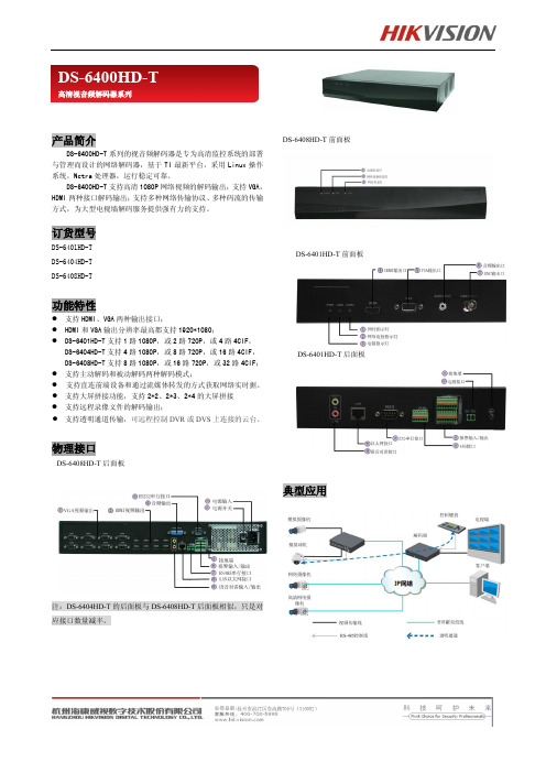
产品简介
DS-6400HD-T 系列的视音频解码器是专为高清监控系统的部署 与管理而设计的网络解码器,基于 TI 最新平台,采用 Linux 操作 系统,Netra 处理器,运行稳定可靠。
DS-6400HD-T 支持高清 1080P 网络视频的解码输出;支持 VGA, HDMI 两种接口解码输出;支持多种网络传输协议、多种码流的传输 方式,为大型电视墙解码服务提供强有力的支持。
ds6408hdt前面板ds6401hdt前面板ds6401hdt后面板典型应用ds6400hdt高清视音频解码器系列技术参数型号ds6401hdtds6404hdtds6408hdtvga路数vga输出分辨率192010806050hz1600120060hz1280102460hz12807205060hz102476860hzhdmi路数hdmi输出分辨率192010806050hz1600120060hz1280102460hz12807205060hz102476860hzbnc输出解码分辨率500w及以下的分辨率解码通道1632解码能力路500w1路1080p2720p4路4cif路500w4路1080p8720p16路4cif路500w8路1080p16720p32路4cif画面分割数141491614916个rj4510m100m1000mbps自适应以太网接口语音对讲个输入1个输出35mm音频接口电平
解码能力 参
数 画面分割数
网络接口
外 语音对讲
部 音频输出
接 报警输入
口 报警输出
串行接口
电源
功耗
其 工作温度
他 工作湿度
尺寸
重量
DS-6401HD-T
电度表型号查询1

DTS 147 DTS 148 DTS 149 DTS 151 DTS 159 DTS 166 DTS 169 DTS 171 DTS 172 DTS 175 DTS 178 DTS 179 DTS 182 DTS 183 DTS 185 DTS 188 DTS 188S DTS(X) 188 DTS 191 DTS 193 DTS 194 DTS 196 DTS 199 DTS 200 DTS 200-2 DTS 207 DTS 208 DTS 208-1 DTS 208-2 DTS 209 DTS 211 DTS 212 DTS 213 DTS 216 DTS 220 DTS 222 DTS 226 DTS 229 DTS 232 DTS 235 DTS 249 DTS 251 DTS 256
三相四线电子式电度表 三相四线电子式电度表 三相四线电子式电度表 三相四线电子式电度表 三相四线电子式电度表 三相四线电子式电度表 三相四线电子式电度表 三相四线电子式电度表 三相四线电子式电度表 三相四线电子式电度表 三相四线电子式电度表 三相四线电子式电度表 三相四线电子式电度表 三相四线电子式电度表 三相四线电子式电度表 三相四线电子式电度表 三相四线电子式电度表
三相四线电子式载波组合电度表 三相四线电子式有功无功组合电度表
三相四线电子式电度表 三相四线电子式电度表 三相四线电子式电度表 三相四线电子式电度表 三相四线电子式电度表 三相四线电子式电度表 三相四线电子式电度表 三相四线电子式电度表 三相四线电子式电度表 三相四线电子式电度表 三相四线电子式电度表 三相四线电子式电度表 三相四线电子式电度表 三相四线电子式电度表 三相四线电子式电度表 三相四线电子式电度表 三相四线电子式电度表 三相四线电子式电度表
监控摄像头的报价
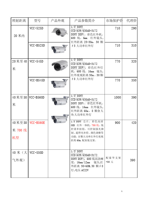
照射距离 型号产品外观 产品参数简介 市场保护价 代理价20米内VCC-525D 1/3'SONY CCD(639/638AK+3172 SONY DSP),彩色红外机,600线,6mm 红外镜头,红外距离25-30m,30颗∮5大功率红外灯 710 290 VCC-B525D710 310 20米至40米 VCC-545D 1/3'SONYCCD(639/638AK+3172SONY DSP),彩色红外灯机,600线,16mm 镜头,红外夜视距离50m ,30颗∮8大功率红外灯 770 320 VCC-B545D770 350 40米至50米VCC-B560D1/3'SONY CCD(639/638AK+3172 SONY DSP),彩色红外机,600线,16mm 红外镜头,红外距离60m ,8颗食人鱼大功率红外灯1000 390 40米至50米700线机型 VCC-B560E 1/3'SONY 芯片,彩色高清OSD 红外一体机,700线,线控菜单按钮,可控制强光抑制、超背光补偿、颜色调整等功能,8颗大功率红外灯夜视距离60m.配原装支架。
900 42040米(大气外观) VCC-550D1/3'SONY CCD(639/638AK+3172 SONY DSP),600线高清晰度,16mm/12mm 镜头,红外距离50-60M,30颗∮8灯,电压AC22V 配豪华支架+30元390700线版本 VCC-B550E1/3'SONY CCD,700线高清晰度,16mm/12mm 镜头,30颗白光灯照射距离30-40M,电压AC22V配豪华支架+30元 46050米至80米V VCC-588DZ1/3'SONY CCD(639/638AK+3172 SONY DSP),彩色变倍红外机,600线,9-22mm 变焦镜头,红外距离50-80m,108颗红外灯 1250 510 650线版本 VCC-588KZ1/3'SONY CCD,宽动态高清OSD 红外变倍摄像机,650线,线控菜单按钮,可控制强光抑制、宽动态功能、颜色调整等功能,内置9-22mm 手动变倍镜头.红外夜视距离50-80m。
Analog Devices ADT6401 ADT6402温度开关数据手册说明书
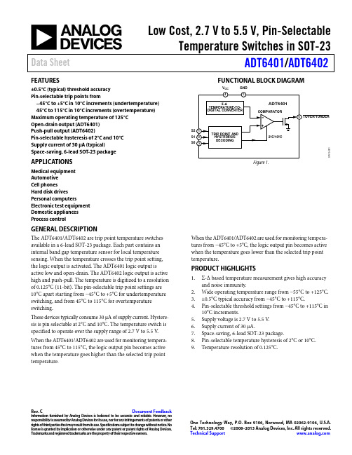
Low Cost, 2.7 V to 5.5 V, Pin-SelectableTemperature Switches in SOT-23 Data Sheet ADT6401/ADT6402Rev. C Document FeedbackInformation furnished by Analog Devices is believed to be accurate and reliable. However, noresponsibility is assumed by Analog Devices for its use, nor for any infringements of patents or other rights of third parties that may result from its use. Specifications subject to change without notice. No license is granted by implication or otherwise under any patent or patent rights of Analog Devices. T rademarks and registered trademarks are the property of their respective owners. One Technology Way, P.O. Box 9106, N orwood, MA 02062-9106, U.S.A. Tel: 781.329.4700 ©2008–2013 Analog Devices, Inc. All rights reserved. Technical Support FEATURES±0.5°C (typical) threshold accuracyPin-selectable trip points from−45°C to +5°C in 10°C increments (undertemperature) 45°C to 115°C in 10°C increments (overtemperature) Maximum operating temperature of 125°COpen-drain output (ADT6401)Push-pull output (ADT6402)Pin-selectable hysteresis of 2°C and 10°CSupply current of 30 µA (typical)Space-saving, 6-lead SOT-23 package APPLICATIONSMedical equipmentAutomotiveCell phonesHard disk drivesPersonal computersElectronic test equipmentDomestic appliancesProcess controlFUNCTIONAL BLOCK DIAGRAMV CC GNDS2S1S0Figure 1.GENERAL DESCRIPTIONThe ADT6401/ADT6402 are trip point temperature switches available in a 6-lead SOT-23 package. Each part contains an internal band gap temperature sensor for local temperature sensing. When the temperature crosses the trip point setting, the logic output is activated. The ADT6401 logic output is active low and open-drain. The ADT6402 logic output is active high and push-pull. The temperature is digitized to a resolution of 0.125°C (11-bit). The pin-selectable trip point settings are 10°C apart starting from −45°C to +5°C for undertemperature switching, and from 45°C to 115°C for overtemperature switching.These devices typically consume 30 μA of supply current. Hystere-sis is pin selectable at 2°C and 10°C. The temperature switch is specified to operate over the supply range of 2.7 V to 5.5 V. When the ADT6401/ADT6402 are used for monitoring tempera-tures from 45°C to 115°C, the logic output pin becomes active when the temperature goes higher than the selected trip point temperature. When the ADT6401/ADT6402 are used for monitoring tempera-tures from −45°C to +5°C, the logic output pin becomes active when the temperature goes lower than the selected trip point temperature.PRODUCT HIGHLIGHTS1.Σ-Δ based temperature measurement gives high accuracyand noise immunity.2.Wide operating temperature range from −55°C to +125°C.3.±0.5°C typical accuracy from −45°C to +115°C.4.Pin-selectable threshold settings from −45°C to +115°C in10°C increments.5.Supply voltage is 2.7 V to 5.5 V.6.Supply current of 30 μA.7.Space-saving, 6-lead SOT-23 package.8.Pin-selectable temperature hysteresis of 2°C or 10°C.9.Temperature resolution of 0.125°C.ADT6401/ADT6402Data SheetRev. C | Page 2 of 12TABLE OF CONTENTSFeatures .............................................................................................. 1 Applications ....................................................................................... 1 Functional Block Diagram .............................................................. 1 General Description ......................................................................... 1 Product Highlights ........................................................................... 1 Revision History ............................................................................... 2 Specifications ..................................................................................... 3 Absolute Maximum Ratings ............................................................ 4 ESD Caution .................................................................................. 4 Pin Configurations and Function Descriptions ........................... 5 Typical Performance Characteristics ............................................. 6 Typical Application Circuits ............................................................ 8 Theory of Operation .........................................................................9 Circuit Information .......................................................................9 Converter Details ..........................................................................9 Pin-Selectable Trip Point and Hysteresis ...................................9 Temperature Conversion ........................................................... 10 Applications Information .............................................................. 11 Thermal Response Time ........................................................... 11 Self-Heating Effects .................................................................... 11 Supply Decoupling ..................................................................... 11 Temperature Monitoring ........................................................... 11 Outline Dimensions ....................................................................... 12 Ordering Guide .. (12)REVISION HISTORY4/13—Rev. B to Rev. CChange to Figure 16 ......................................................................... 8 9/12—Rev. A to Rev. BChange to Specifications Table 1, Supply Current Parameter .... 3 6/10—Rev. 0 to Rev. AChanges to Table 4 (9)Updated Outline Dimensions ....................................................... 12 5/08—Revision 0: Initial VersionData Sheet ADT6401/ADT6402 SPECIFICATIONST A = −55°C to +125°C, V CC = 2.7 V to 5.5 V, open-drain R PULL-UP = 10 kΩ, unless otherwise noted.Table 1.Parameter Min Typ Max Unit Test Conditions/Comments TEMPERATURE SENSOR AND ADCThreshold Accuracy ±0.5 ±6 °C T A = −45°C to −25°C±0.5 ±4 °C T A = −15°C to +15°C±0.5 ±4 °C T A = 35°C to 65°C±0.5 ±6 °C T A = 75°C to 115°CADC Resolution 11 BitsTemperature Conversion Time 30 ms Time necessary to complete a conversion Update Rate 600 ms Conversion started every 600 ms Temperature Threshold Hysteresis 2 °C Pin selectable, depends on S0, S1, S2 settings10 °C Pin selectable, depends on S0, S1, S2 settings DIGITAL OUTPUT (OPEN-DRAIN)Output High Current, I OH 10 nA Leakage current, V CC = 2.7 V and V OH = 5.5 V Output Low Voltage, V OL0.3 V I OL = 1.2 mA, V CC = 2.7 V0.4 V I OL = 3.2 mA, V CC = 4.5 VOutput Capacitance, C OUT110 pF R PULL-UP = 10 kΩDIGITAL OUTPUT (PUSH-PULL)Output Low Voltage, V OL0.3 V I OL = 1.2 mA, V CC = 2.7 V0.4 V I OL = 3.2 mA, V CC = 4.5 VOutput High Voltage, V OH0.8 × V CC V I SOURCE = 500 µA, V CC = 2.7 VV CC − 1.5 V I SOURCE = 800 µA, V CC = 4.5 VOutput Capacitance, C OUT110 pFPOWER REQUIREMENTSSupply Voltage 2.7 5.5 VSupply Current 30 55 µA1 Guaranteed by design and characterization.Rev. C | Page 3 of 12ADT6401/ADT6402Data SheetRev. C | Page 4 of 12ABSOLUTE MAXIMUM RATINGSTable 2.Parameter RatingV CC to GND−0.3 V to +7 VS0, S1, S2 Input Voltage to GND −0.3 V to V CC + 0.3 V Open-Drain Output Voltage to GND −0.3 V to +7 VPush-Pull Output Voltage to GND −0.3 V to V CC + 0.3 V Input Current on All Pins 20 mA Output Current on All Pins 20 mA ESD rating (HBM)1.5 kVOperating Temperature Range −55°C to +125°C Storage Temperature Range−65°C to +160°C Maximum Junction Temperature, T JMAX 150.7°C 6-Lead SOT-23 (RJ-6)Power Dissipation 1 W MAX = (T JMAX − T A 2)/θJA Thermal Impedance 3θJA , Junction-to-Ambient (Still Air) 229.6°C/W IR Reflow Soldering (RoHS-Compliant Package)Peak Temperature260°C (+0°C) Time at Peak Temperature 20 sec to 40 sec Ramp-Up Rate 3°C/sec maximum Ramp-Down Rate−6°C/sec maximum Time 25°C to Peak Temperature8 minute maximum1Values relate to package being used on a standard 2-layer PCB, which gives aworst-case θJA . Refer to Figure 2 for a plot of maximum power dissipation vs. ambient temperature (T A ). 2T A = ambient temperature. 3Junction-to-case resistance is applicable to components featuring a preferential flow direction, for example, components mounted on a heat sink. Junction-to-ambient resistance is more useful for air-cooled, PCB-mounted components.Stresses above those listed under Absolute Maximum Ratings may cause permanent damage to the device. This is a stress rating only; functional operation of the device at these or any other conditions above those indicated in the operationalsection of this specification is not implied. Exposure to absolute maximum rating conditions for extended periods may affect device reliability.0.90125TEMPERATURE (°C)M A X I M U M P OW E R D I S S I P A T I O N (W )0.80.70.60.50.40.30.20.1–55–50–40–30–20–10010203040506070809010011012007415-002Figure 2. SOT-23 Maximum Power Dissipation vs. TemperatureESD CAUTIONData SheetADT6401/ADT6402Rev. C | Page 5 of 12PIN CONFIGURATIONS AND FUNCTION DESCRIPTIONSS21S12S03TOVER/TUNDER 6GND5V CC4ADT6401TOP VIEW (Not to Scale)07415-003Figure 3. ADT6401 Pin Configuration S21S12S03TOVER/TUNDER 6GND 5V CC4ADT6402TOP VIEW (Not to Scale)07415-004Figure 4. ADT6402 Pin ConfigurationADT6401/ADT6402Data SheetRev. C | Page 6 of 12TYPICAL PERFORMANCE CHARACTERISTICS35–0.5TEMPERATURE ACCURACY (°C)P E R C E N T A G E O F P A R T S S A M P L E D (%)30252015105–0.4–0.3–0.2–0.10.10.20.30.40.507415-015Figure 5. Trip Threshold Accuracy 450TEMPERATURE (°C)I C C (µA )403530252015105–60–40–20204060801001201403.3V5V07415-016Figure 6. Operating Supply Current vs. Temperature1800–80–60–40–20020406080100120TEMPERATURE (°C)O U T P U T S O U R C E R E S I S T A N C E (Ω)160140120100806040201405.5V3.3V2.7V07415-017Figure 7. ADT6402 Output Source Resistance vs. Temperature–80–60–40–20020406080100120140800TEMPERATURE (°C)O U T P U T S I N K R E S I S T A N C E (Ω)5.5V3.3V2.7V7060504030201007415-018Figure 8. Output Sink Resistance vs. Temperature120TIME (s)T E M P E R A T U R E (°C)012.8100806040200.81.62.43.24.04.85.66.47.28.08.89.610.411.212.007415-019Figure 9. Thermal Step Response in Perfluorinated Fluid1400TIME (s)T E M P E R A T U R E (°C )12010080604020 3.67.210.814.418.021.625.228.832.436.039.643.246.850.454.057.661.207415-020Figure 10. Thermal Step Response in Still AirData SheetADT6401/ADT6402Rev. C | Page 7 of 12110–60–50–40–30–20–10102030405060708090100110120130TEMPERATURE (°C)H Y S T E R E S I S (°C )1086429753107415-021Figure 11. Hysteresis vs. Trip TemperatureA CH1 1.68V07415-022Figure 12. ADT6401 Start-Up and Power-Down DelayA CH1 1.68V07415-023Figure 13. ADT6401 Start-Up Delay4502.4 5.6V CC (V)I C C (µA )4035302520151052.62.83.03.23.43.63.84.04.24.44.64.85.05.25.407415-024Figure 14. Operating Supply Current vs. Voltage Over TemperatureADT6401/ADT6402Data SheetRev. C | Page 8 of 12TYPICAL APPLICATION CIRCUITS07415-011Figure 15. Microprocessor Alarm 07415-012Figure 16. Overtemperature Fan ControlOVER TEMPERATUREUNDER TEMPERATUREOUT OF RANGE07415-013Figure 17. Temperature Window AlarmsData SheetADT6401/ADT6402Rev. C | Page 9 of 12THEORY OF OPERATIONCIRCUIT INFORMATIONThe ADT6401/ADT6402 are 11-bit digital temperature sensors with a 12th bit acting as the sign bit. An on-board temperature sensor generates a voltage precisely proportional to absolute temperature, which is compared to an internal voltage reference and input to a precision digital modulator. The 12-bit output from the modulator is input into a digital comparator, where it is compared with a pin-selectable trip level. The output trip pin is activated if the temperature measured is greater than, or less than, the pin-selectable trip level. Overall accuracy for the ADT6401/ ADT6402 is ±6°C (maximum) from −45°C to +115°C.The on-board temperature sensor has excellent accuracy and linearity over the entire rated temperature range without needing correction or calibration by the user. The ADT6401 has active low, open-drain output structures that can sink current. The ADT6402 has active high, push-pull output structures that can sink and source current. On power-up, the output becomes active when the first conversion is completed, which typically takes 30 ms.The sensor output is digitized by a first-order, ∑-∆ modulator, also known as the charge balance type analog-to-digital converter (ADC). This type of converter utilizes time domain oversampling and a high accuracy comparator to deliver 11 bits of effective accuracy in an extremely compact circuit.CONVERTER DETAILSThe Σ-Δ modulator consists of an input sampler, a summing network, an integrator, a comparator, and a 1-bit digital-to-analog converter (DAC). Similar to the voltage-to-frequency converter, this architecture creates a negative feedback loop and minimizes the integrator output by changing the duty cycle of the comparator output in response to input voltage changes. The comparator samples the output of the integrator at a much higher rate than the input sampling frequency; this is called oversampling. Oversampling spreads the quantization noise over a much wider band than that of the input signal, improving overall noise performance and increasing accuracy.PIN-SELECTABLE TRIP POINT AND HYSTERESISThe temperature trip point and hysteresis values for the ADT6401/ADT6402 are selected using Pin S0, Pin S1, and Pin S2. These three pins can be connected to V CC , tied to GND, or left floating. The ADT6401/ADT6402 decode the inputs on S0, S1, and S2 to determine the temperature trip point and hysteresis value, as outlined in Table 4.The ADT6401 overtemperature/undertemperature output is intended to interface to reset inputs of microprocessors. The ADT6402 is intended for driving circuits of applications, such as fan control circuits.Table 4. Selecting Trip Points and Hysteresis 1S2 S1 S0 Temperature Trip Point Hysteresis 0 0 0 +45°C 2°C 0 0 1 +55°C 2°C 0 0 Float +65°C 2°C 0 1 0 +75°C 2°C 0 1 1 +85°C 2°C 0 1 Float +95°C 2°C 0 Float 0 +105°C 2°C 0 Float 1 +115°C 2°C 0 Float Float +55°C 10°C 1 0 0 +65°C 10°C 1 0 1 +75°C 10°C 1 0 Float +85°C 10°C 1 1 0 +95°C 10°C 1 1 1 +105°C 10°C 1 1 Float +115°C 10°C 1 Float 0 +5°C 2°C 1 Float 1 −5°C 2°C 1 Float Float −15°C 2°C Float 0 0 −25°C 2°C Float 0 1 −35°C 2°C Float 0 Float −45°C 2°C Float 1 0 +5°C 10°C Float 1 1 −5°C 10°C Float 1 Float −15°C 10°C Float Float 0 −25°C 10°C Float Float 1 −35°C 10°C FloatFloat Float−45°C10°C10 = pin tied to GND, 1 = pin tied to V CC , Float = pin left floating.ADT6401/ADT6402Data SheetRev. C | Page 10 of 12HysteresisA hysteresis value of 2°C or 10°C can be selected. The digital comparator ensures excellent accuracy for the hysteresis value. Hysteresis prevents oscillation on the output pin when the temperature is approaching the trip point and after the output pin is activated. For example, if the temperature trip is 45°C and the hysteresis selected is 10°C, the temperature must go as low as 35°C before the output deactivates.TEMPERATURE CONVERSIONThe conversion clock for the part is generated internally. No external clock is required. The internal clock oscillator runs an automatic conversion sequence. During this automatic conversion sequence, a conversion is initiated every 600 ms. At this time, the part powers up its analog circuitry and performs a temperature conversion.This temperature conversion typically takes 30 ms, after which the analog circuitry of the part automatically shuts down. The analog circuitry powers up again 570 ms later, when the 600 ms timer times out and the next conversion begins. The result of the most recent temperature conversion is compared with the factory-set trip point value. If the temperature measured is greater than the trip point value, the output is activated. The output is deactivated once the temperature crosses back over the trip point threshold, plus whatever temperature hysteresis is selected. Figure 18 to Figure 21 show the transfer function for the output trip pin of each generic model.HYSTERESIS07415-006Figure 18. ADT6401 TOVER Transfer FunctionHYSTERESIS07415-007Figure 19. ADT6402 TOVER Transfer FunctionHYSTERESIS07415-008Figure 20. ADT6401 TUNDER Transfer FunctionHYSTERESIS07415-009Figure 21. ADT6402 TUNDER Transfer FunctionData SheetADT6401/ADT6402Rev. C | Page 11 of 12APPLICATIONS INFORMATIONTHERMAL RESPONSE TIMEThe time required for a temperature sensor to settle to a specified accuracy is a function of the thermal mass of the sensor and the thermal conductivity between the sensor and the object being sensed. Thermal mass is often considered equivalent to capacitance. Thermal conductivity is commonly specified using the symbol Q and can be thought of as thermal resistance. It is commonly specified in units of degrees per watt of powertransferred across the thermal joint. Thus, the time required for the ADT6401/ADT6402 to settle to the desired accuracy is dependent on the characteristics of the SOT-23 package, the thermal contact established in that particular application, and the equivalent power of the heat source. In most applications, the settling time is best determined empirically.SELF-HEATING EFFECTSThe temperature measurement accuracy of the ADT6401/ ADT6402 can be degraded in some applications due to self-heating. Errors can be introduced from the quiescent dissipation and power dissipated when converting. The magnitude of these temperature errors depends on the thermal conductivity of the ADT6401/ADT6402 package, the mounting technique, and the effects of airflow. At 25°C, static dissipation in the ADT6401/ ADT6402 is typically 99 µW operating at 3.3 V . In the 6-lead SOT-23 package mounted in free air, this accounts for a tempera-ture increase due to self-heating ofΔT = P DISS × θJA = 99 µW × 240°C/W = 0.024°CIt is recommended that current dissipated through the device be kept to a minimum because it has a proportional effect on the temperature error.SUPPLY DECOUPLINGThe ADT6401/ADT6402 should be decoupled with a 0.1 µF ceramic capacitor between V CC and GND. This is particularly important when the ADT6401/ADT6402 are mounted remotely from the power supply. Precision analog products such as the ADT6401/ADT6402 require well-filtered power sources.Because the ADT6401/ADT6402 operate from a single supply, it may seem convenient to tap into the digital logic power supply. Unfortunately, the logic supply is often a switch-mode design, which generates noise in the 20 kHz to 1 MHz range. In addition, fast logic gates can generate glitches that are hundreds of millivolts in amplitude due to wiring resistance and inductance. If possible, the ADT6401/ADT6402 should be powered directly from the system power supply. This arrangement, shown in Figure 22, isolates the analog section from the logic-switching transients. Even if a separate power supply trace is not available, generous supply bypassing reduces supply line induced errors. Local supply bypassing consisting of a 0.1 µF ceramic capacitor is advisable to achieve the temperature accuracy specifications. This decoupling capacitor must be placed as close as possible to the ADT6401/ADT6402 V CC pin.07415-010Figure 22. Separate Traces Used to Reduce Power Supply NoiseTEMPERATURE MONITORINGThe ADT6401/ADT6402 are ideal for monitoring the thermal environment within electronic equipment. For example, the surface-mount package accurately reflects the exact thermal conditions that affect nearby integrated circuits.The ADT6401/ADT6402 measure and convert the temperature at the surface of its own semiconductor chip. When the ADT6401/ ADT6402 are used to measure the temperature of a nearby heat source, the thermal impedance between the heat source and the ADT6401/ADT6402 must be as low as possible.As much as 60% of the heat transferred from the heat source to the thermal sensor on the ADT6401/ADT6402 die is discharged via the copper tracks, package pins, and bond pads. Of the pins on the ADT6401/ADT6402, the GND pin transfers most of the heat. Therefore, to monitor the temperature of a heat source, it is recommended that the thermal resistance between the ADT6401/ ADT6402 GND pin and the GND of the heat source be reduced as much as possible.For example, the unique properties of the ADT6401/ADT6402 can be used to monitor a high power dissipation microproces-sor. The ADT6401/ADT6402 device in its SOT-23 package is mounted directly beneath the pin grid array (PGA) package of the microprocessor. The ADT6401/ADT6402 require no external characterization.ADT6401/ADT6402Data SheetRev. C | Page 12 of 12OUTLINE DIMENSIONSCOMPLIANT TO JEDEC STANDARDS MO-178-AB1.300.150.050.200.08MIN12-16-2008-AFigure 23. 6-Lead Small Outline Transistor Package [SOT-23](RJ-6)Dimensions shown in millimetersORDERING GUIDEModel 1Temperature RangePackage Description Package Option OrderingQuantity Branding ADT6401SRJZ-RL7 −55°C to +125°C 6-Lead SOT-23 RJ-6 3,000 T30 ADT6402SRJZ-RL7−55°C to +125°C 6-Lead SOT-23 RJ-6 3,000 T321Z = RoHS Compliant Part.©2008–2013 Analog Devices, Inc. All rights reserved. Trademarks andregistered trademarks are the property of their respective owners. D07415-0-4/13(C)。
双电源版DTS解码板(精)

DTS AC3 解码板使用说明开机进行音量初始化并控制音量到前次音量保存处,初始化完毕显示各声道音量初始值并处于接受命令状态!音量每改变一次,相对应的声道显示值将改变一次安装和操作说明一安装说明注:特别要注意的是千万不能让控制板的音量信号输出线触碰到功放外壳; GND地线和电源引线!!否则触碰到的话将永久损坏控制板! 1:将解码板的+12V标志(见板子背面),接经过稳压后的+12V电压! -12V标志(见板子背面),接经过稳压后的-12V电压!另外的GND标志接接地线(或是功放机的外壳) 2:将控制板的旋钮安装在功放音量音量调节电位器的位置并用螺丝固定好,将遥控接收头安装在面板上,要将接收头的半球型接收面露在机箱外以便接收遥控器的发射信号!将液晶显示屏固定在功放面板的显眼位置以便观察! 3: 稳压块LM7805因解码板工作电流较大实际安装使用时应该加大散热器以便长期稳定工作,否则稳压模块有可能因过热而损坏! 4:解码板板音频输出部分中“FL”标志为前置左声道音频输出,“FR”标志为前置右声道音频输出,“SL”标志为环绕左声道音频输出,“SR”标志为环绕右声道音频输出,“CEN”标志为中置声道音频输出,“SW”标志为重低音声道音频输出(见板子背面) 5: 解码板信号输入部分中“AUX L”标志为模拟左声道音频输入,“AUX R”标志为模拟右声道音频输入,“COX1”标志为同轴1数字音频输入,“COX2”标志为同轴2数字音频输入,“OPT”标志为光纤数字音频输入,“FL1”标志为模拟前置左声道音频输入,“FR1”标志为模拟前置右声道音频输入,“SL1”标志为模拟环绕左声道音频输入,“SR1”标志为模拟环绕右声道音频输入,“CEN1”标志为模拟中置声道音频输入,“SW1”标志为模拟重低音声道音频输入(板子背面)二液晶显示字符说明 1: 当输入音频信号后第一行最右边将显示输入信号的编码格式。
当输入的音频信号是DTS音频信号时则显示“ DTS”;当输入的音频信号是杜比AC3音频信号时则显示“ AC3”;其他的音频信号输入则显示“ PCM”;没有音频信号输入时则显示空白(无字符显示)三手动操作说明 1:控制板默认为音量统调状态,此时调节旋钮为调节音量的大小!顺时针为音量增大,反时针为音量减小! 2:按压旋钮杆为功能切换功能!依次顺序为:音量统一调节;音源:音源输入切换;声场:数字声场切换;模式:聆听模式切换;前置左声道 FL音量调节;前置右声道FR音量调节;环绕声道延时时间调节;环绕左声道SL音量调节;环绕右声道SR音量调节;中置声道延时时间调节;中置声道CEN 音量调节;重低音音量调节SW;音调功能开关;高音音量调节;中音音量调节;低音音量调节(每按动一次按压开关,功能切换一个!) 3:音源:音源输入切换状态,此时调节旋钮为依次选择4组音源通道:“光纤” ; “同轴1 ” ; “同轴2”;“模拟2”(为模拟2声道输入);“模拟6”(为模拟5.1声道输入)! 4:声场:数字声场模式切换状态,此时调节旋钮为依次选择8种声场模式:“矩阵” ; “现场” ; “礼堂” ; “广场” ; “模拟” ; “大厅” ; “合唱” ; “剧院” 5: 模式:聆听模式切换状态,此时调节旋钮为依次选择4种模式:“自动” ; “立体声” ; “杜比” ; “测试” 6: 前置左声道FL音量调节状态,此时调节旋钮为调节音量的大小!顺时针为音量增大,反时针为音量减小! 7:前置右声道FR音量调节状态,此时调节旋钮为调节音量的大小!顺时针为音量增大,反时针为音量减小! 8:环绕声道延时时间选择状态,此时调节旋钮为调节延时的大小!顺时针为延时增大,反时针为延时减小! 9:环绕声道SL 音量调节状态,此时调节旋钮为调节音量的大小!顺时针为音量增大,反时针为音量减小! 10:环绕声道SR音量调节状态,此时调节旋钮为调节音量的大小!顺时针为音量增大,反时针为音量减小! 11:中置声道延时时间选择状态,此时调节旋钮为调节延时的大小!顺时针为延时增大,反时针为延时减小! 12:中置CEN 音量调节状态,此时调节旋钮为调节音量的大小!顺时针为音量增大,反时针为音量减小! 13: 重低音SW音量调节状态,此时调节旋钮为调节音量的大小!顺时针为音量增大,反时针为音量减小! 14:音调功能开关调节状态,此时调节旋钮为循环切换音调功能开关!显示“开”表示音调功能开通,显示“关”表示音调功能关闭!15: 高音调节状态,此时调节旋钮为调节高音大小!顺时针为高音增加,反时针为高音减小!前面显示的“+”表示高音提升,“-”表示高音衰减! 16: 中音调节状态,此时调节旋钮为调节中音大小!顺时针为中音增加,反时针为中音减小!前面显示的“+”表示中音提升,“-”表示中音衰减! 17: 低音调节状态,此时调节旋钮为调节低音大小!顺时针为低音增加,反时针为低音减小!前面显示的“+”表示低音提升,“-”表示低音衰减! 18:音量统一调节状态,此时调节旋钮为调节音量的大小!顺时针为音量增大,反时针为音量减小!三遥控操作说明 1:遥控器的VOL+键为音量+键(为调节增加功能按键!),VOL-键为音量-键(为调节减小功能按键!) 2:遥控器上的播放暂停键为静音功能键,按一次为6声道同时静音,再按一次开通声音!循环切换!(静音时液晶屏将显示“静音”;取消静音显示恢复正常!)注意:在静音状态时其他功能将失效,直到取消静音状态才会恢复!!! 3:遥控器1键为前置左声道FL选择键,在前置左声道FL状态下按VOL-键为前置左声道FL音量减小,按VOL+为前置左声道FL音量增加! 4:遥控器2键为前置右声道FR选择键,在前置右声道FR状态下按VOL-键为前置右声道FR音量减小,按VOL+为前置右声道FR音量增加! 5:遥控器3键为环绕左声道SL选择键,在环绕左声道SL状态下按VOL-键为环绕左声道SL音量减小,按VOL+为环绕左声道SL音量增加! 6:遥控器4键为环绕右声道SR选择键,在环绕右声道SR状态下按VOL-键为环绕右声道SR音量减小,按VOL+为环绕右声道SR音量增加! 7:遥控器5键为中置声道CEN选择键,中置声道CEN状态下按VOL-键为中置声道CEN音量减小,按VOL+为中置声道CEN音量增加!8:遥控器6键为超重低音SW调节选择键,超重低音SW音量调节状态下按VOL-键为超重低音SW 声道音量减小,按VOL+为超重低音SW声道音量增加! 9:遥控器0键为音量统调(所有声道)选择键,在所有声道状态下按VOL-键为所有声道音量减小,按VOL+为所有声道音量增加!(开机默认为该状态!当10秒没有任何控制命令输入时控制板将返回到此状态并保存音量值) 10: 遥控器静音键为静音功能控制键! 11: 遥控器U/SD键为功能选择控制键!依次按该键分别选择:音量统一调节;音源:音源输入切换;声场:数字声场切换;模式:聆听模式切换;前置左声道FL音量调节;前置右声道FR音量调节;环绕声道延时时间调节;环绕左声道SL音量调节;环绕右声道SR音量调节;中置声道延时时间调节;中置声道CEN音量调节;重低音音量调节SW;音调功能开关;高音音量调节;中音音量调节;低音音量调节!(每按动一次该键,功能切换一个!和手动控制的旋钮按压开关功能相同) 12: 遥控器RPT键为音源输入切换直接选择键!依次按该键分别选择4组音源通道:“光纤” ;;“同轴1”; “同轴2”;“模拟2”(为模拟2声道输入);“模拟6”(为模拟5.1声道输入)! 13: 遥控器MODE键为聆听模式直接选择键!依次按该键分别选择4种模式:“自动” ; “立体声” ; “杜比” ; “测试” 14: 遥控器EQ键为声场数字声场直接选择键!依次按该键分别选择:8种声场模式:“矩阵” ; “现场” ; “礼堂” ; “广场” ; “模拟” ; “大厅” ; “合唱” ; “剧院” 15:当调节中出现液晶显示屏声道音量值不变化时表示该功能以被调节至最大或最小值!(主音量最大值79,最小值00;各个声道音量最大值15,最小值00),中置延时最大15ms,最小00ms;环绕延时最大30ms,最小15ms 16:音调功能开关调节状态,此时按VOL+为循环切换音调功能开关!显示“开”表示音调功能开通,显示“关”表示音调功能关闭! 17: 高音调节状态,按VOL+为高音增加,按VOL-为高音减小!前面显示的“+”表示高音提升,“-”表示高音衰减! 18: 中音调节状态,按VOL+为中音增加,按VOL-为中音减小!前面显示的“+”表示中音提升,“-”表示中音衰减! 19: 低音调节状态,按VOL+为低音增加,按VOL-为低音减小!前面显示的“+”表示低音提升,“-”表示低音衰减!噪声测试模式说明:当手动或是遥控设置了模式为测试状态时;此时液晶屏第一行将显示当前的噪声输出通道!输出通道从前置左声道开始每3秒切换一个声道,循环切换!(前置左声道FL→前置右声道FR→ 中置声道CEN→重低音声道SW→环绕左声道SL→环绕右声道SR)!退出测试模式:使用遥控器退出测试模式为按一次“VOL+”键3秒内将退出测试模式并将模式切换到“自动”!手动退出测试模式为按住功能选择开关3秒后松开功能选择开关则将退出测试模式并将模式设置为“自动” 画面切换到前置左声道音量调节!。
CD播放机解码光头型号大全
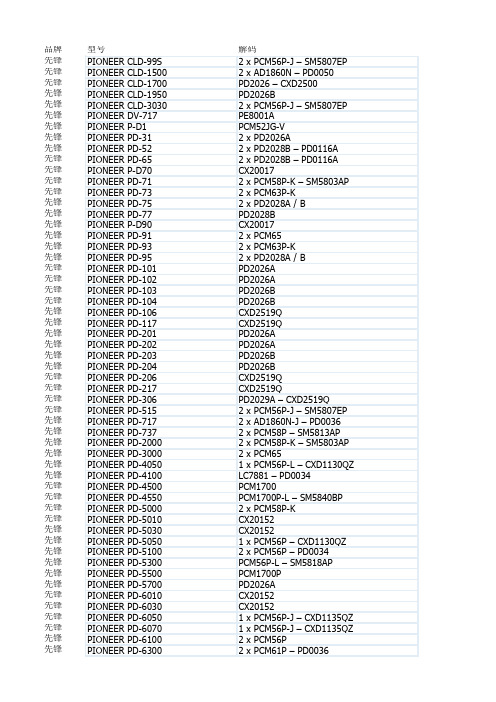
PIONEER PD-6500 PIONEER PD-7010 PIONEER PD-7030 PIONEER PD-7050 PIONEER PD-7070 PIONEER PD-7100 PIONEER PD-7300 PIONEER PD-7500 PIONEER PD-7700 PIONEER PD-8030 PIONEER PD-8070 PIONEER PD-8500 PIONEER PD-8700 PIONEER PD-9010X PIONEER PD-9300 PIONEER PD-9700 PIONEER PD-D6 PIONEER PD-F705 PIONEER PD-HL5 PIONEER PD-M70 PIONEER PD-M407 PIONEER PD-M427 PIONEER PD-M700 PIONEER PD-M910 PIONEER PDR-04 PIONEER PDR-05 PIONEER PDR-609 PIONEER PDR-W739 PIONEER PDR-W839 PIONEER PD-S06 PIONEER PD-S501 PIONEER PD-S502 PIONEER PD-S503 PIONEER PD-S504 PIONEER PD-S505 PIONEER PD-S506 PIONEER PD-S507 PIONEER PD-S601 PIONEER PD-S602 PIONEER PD-S603 PIONEER PD-S604 PIONEER PD-S605 PIONEER PD-S701 PIONEER PD-S702 PIONEER PD-S703 PIONEER PD-S705 PIONEER PD-S707 PIONEER PD-S801 PIONEER PD-S802 PIONEER PD-S901 PIONEER PD-S904 PIONEER PD-T01 PIONEER PD-T03 PIONEER PD-T04 PIONEER PD-T05 PIONEER PD-T06
海康解码器使用说明

视音频解码器
用户手册 V2.0.0
杭州海康威视数字技术股份有限公司 技术热线:400-700-5998 2010-9
1
DS-6401HD 用户手册
非常感谢您购买我公司的产品,如果您有什么疑问或需要请随时联系我们。 本手册适用于主控版本 V2.0.0、型号为 DS-6401HD 的视音频解码器。 本手册可能包含技术上不准确的地方、或与产品功能及操作不相符的地方、或印刷错误。我司将根据产 品功能的增强而更新本手册的内容, 并将定期改进或更新本手册中描述的产品或程序。 更新的内容将会在本 手册的新版本中加入,恕不另行通知。若存在手册中对产品的描述与实物不符,一律以实物为准
录
产品概述.........................................................................................................................5 简介.................................................................................................................................5 功能特性.........................................................................................................................5 设备外观.........................................................................................................................7 前面板.............................................................................................................................7 后面板.............................................................................................................................8 报警连线说明 .................................................................................................................8 2.3.1 报警输入连接方式 ............................................................................................ 8 2.3.2 报警输出连接方式 ............................................................................................ 9 2.3.3 接线说明 ............................................................................................................ 9 第 3 章 网络参数配置 ...............................................................................................................10 3.1 建立超级终端 ...............................................................................................................10 3.2 超级终端配置网络参数 .....................................................................................................13 第 4 章 解码器配置 ...................................................................................................................15 4.1 登陆解码配置软件 .......................................................................................................15 4.2 解码器添加 ...................................................................................................................16 4.3 解码器配置 ...................................................................................................................17 4.4 电视墙管理 ...................................................................................................................18 4.5 解码控制.......................................................................................................................20 4.5.1 图像解码控制 ......................................................................................................... 21 4.5.2 轮循解码控制 ......................................................................................................... 23 4.5.3 云台控制 ................................................................................................................. 24 4.6 非本公司网络摄像机接入 ................................................................................................25 4.6.1 添加解码器 ............................................................................................................ 26 4.6.2 配置解码器 ............................................................................................................ 26 附录 1:技术参数............................................................................................................................30 附录 2:非本公司网络摄像机列表 ................................................................................................31
采用杜比定向逻辑解码板自行组建家庭影院

采用杜比定向逻辑解码板自行组建家庭影院
董瑞琪
【期刊名称】《电子制作》
【年(卷),期】1997(000)004
【摘要】近年VCD的风行给人们的视听带来了新的冲击和感受。
视听合一的感觉既不同于Hi-Fi欣赏,也不同于单纯的电视欣赏。
当我们用带有杜比解码器的AV系统去欣赏杜比影碟时,其定位感、时序感及振撼令人神往。
目前,AV市场一派兴旺景象,但笔者最近到市场浏览,发现进口AV功放售价最低也要3000元左右,而国产功放,精品不多,有些功放甚至不伦不类。
最近,经朋友介绍购得一块咸阳银河新技术开发公司生产的专业杜比定向逻辑环绕解码板。
该板是专为发烧友升级改机之用,价格不足300元,且质量上乘。
下面介绍本人以该板为“龙头”组建自己家庭影院的过程。
【总页数】2页(P4-5)
【作者】董瑞琪
【作者单位】无
【正文语种】中文
【中图分类】TN764
【相关文献】
1.杜比实验室车载技术连载之一汽车音响之顶级体验--杜比定向逻辑Ⅱ技术(Dolby ProLogic Ⅱ) [J], 一通
2.杜比定向逻辑与杜比AC-3 [J], 李刚
3.杜比定向逻辑环绕声解码原理及其在家庭影院中的应用 [J], 杨立均
4.漫谈家庭影院系统:有关杜比定向逻辑,THX和AC—3知识 [J], 陈子彪
5.家庭影院请勿乱点鸳鸯谱——VCD配不上杜比定向逻辑 [J], 钱志远
因版权原因,仅展示原文概要,查看原文内容请购买。
嵌入式局部放电检测系统的数字滤波器设计
嵌入式局部放电检测系统的数字滤波器设计郭亮;黄宏新;成永红;陈小林;孟永鹏【期刊名称】《高电压技术》【年(卷),期】2007(33)8【摘要】为较好地抑制来自电源的干扰和连续周期性干扰,提高系统的稳定性和抗干扰性能,介绍了在基于FP-GA的嵌入式局部放电信号检测系统中,对周期性正弦干扰进行抑制的新方法。
根据FIR数字滤波器的原理,利用Simulink和DSP Builder构建了FIR滤波器的仿真计算模型,利用Matlab数字滤波器设计工具得到模型参数,对混叠高、低频干扰信号以后的放电信号进行滤波,达到预定的滤波效果后再将模型转化成能应用在嵌入式系统中的硬件描述语言。
仿真结果验证了基于Simulink和DSP Builder设计硬件数字滤波器方法的可行性。
和传统的设计方法相比,本文所给出的设计方法简化了开发流程、缩短了开发周期。
【总页数】5页(P44-47)【关键词】局部放电;在线监测;嵌入式;数字滤波器;FIR;DSPBuilder【作者】郭亮;黄宏新;成永红;陈小林;孟永鹏【作者单位】西安交通大学电力设备电气绝缘国家重点实验室;杭州市电力局【正文语种】中文【中图分类】TM835.4【相关文献】1.基于GTEM小室的特高频局部放电检测仪校验系统设计 [J], 易满成;王波;苏海博;杨鹏;顾春晖2.基于嵌入式系统的GIS局部放电监测仪设计 [J], 孔梁;郑文栋;黄成军;钱勇3.XLPE电力电缆局部放电检测诊断系统的设计 [J], 李雯雯;高阳;许傲然4.基于超声波的高压线局部放电检测系统的设计 [J], 刘宁;郑亚平;张晨5.基于超声波的高压线局部放电检测系统的设计 [J], 刘宁;郑亚平;张晨因版权原因,仅展示原文概要,查看原文内容请购买。
Fluke 640B Infrared Thermometer说明书
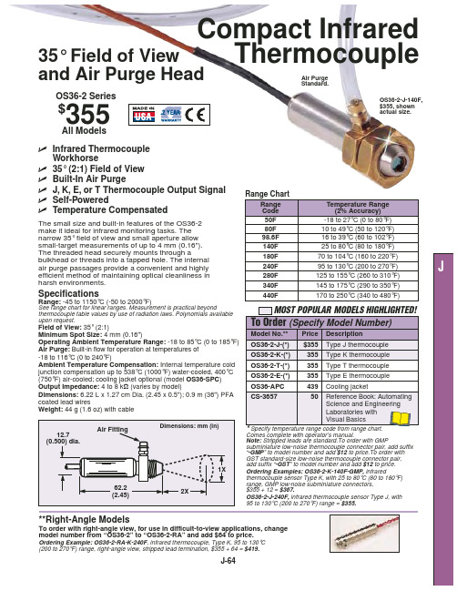
Operating Ambient Temperature Range: -18 to 85°C (0 to 185°F) Air Purge: Built-in flow for operation at temperatures of -18 to 116°C (0 to 240°F)
OS36-2-J-(*) OS36-2-K-(*)
Temperature Range (2% Accuracy)
The small size and built-in features of the OS36-2 make it ideal for infrared monitoring tasks. The
50F
-18 to 27°C (0 to 80°F)
Compact Infrared
35° Field of View
Thermocouple
and Air Purge Head
Air Purge Standard.
OS36-2 Series
$355
OS36-2-J-140F, $355, shown actual size.
All Models
ߜ Infrared Thermocouple
140F
25 to 80°C (80 to 180°F)
180F
70 to 104°C (160 to 220°F)
240F
95 to 130°C (200 to 270°F)
J
efficient method of maintaining optical cleanliness in
280F
125 to 155°C (260 to 310°F)
harsh environments.
- 1、下载文档前请自行甄别文档内容的完整性,平台不提供额外的编辑、内容补充、找答案等附加服务。
- 2、"仅部分预览"的文档,不可在线预览部分如存在完整性等问题,可反馈申请退款(可完整预览的文档不适用该条件!)。
- 3、如文档侵犯您的权益,请联系客服反馈,我们会尽快为您处理(人工客服工作时间:9:00-18:30)。
鼎日株式會
鼎日株式會社
Ding Day Co., LTD.
P-Channel Enhancement Mode Field Effect Transistor
D
G S
ABSOLUTE MAXIUM RATINGS (T A =25℃ unless otherwise noted )
Parameter Symbol Limit Unit
Drain-Source V oltage V DS -60 V Gate-Source V oltage
V GS ±20 V
I D -5.2 A
Drain Current-Continuous ª@Tj=125℃
- Pulse b d
I DM -34
A Drain-source Diode Forward Current ª I S -1.3 A
Maximum Power Dissipation ª P D 2.5 W Operating Junction and Storage Temperature Range
T J ,T STG -55 to 150 ℃
THERMAL CHARACTERISTICS
Thermal Resistance, Junction-to Ambient ª Rth J A 100 ℃/W
鼎日株式會社
1
ELECTRICAL CHARACTERISTICS (T A =25℃ unless otherwise noted)
Parameter Symbol
Condition Min Typ Max Unit
OFF CHARACTERISTICS Drain-Source Breakdown V oltage BV DSS V GS =0V ,I D =-250µA -60 V Zero Gate V oltage Drain Current I DSS V DS =-48V ,V GS =0V -1 µA Gate-Body Leakage
I GSS
V GS =±20V ,V DS =0V ±100
nA
ON CHARACTERITICS
Gate Threshold V oltage
V GS (th) V DS =V GS ,I D =-250µA -1 -1.5 -2.5 V V GS =-10V ,I D =-4.8A 40 45
Drain-Source On-State Resistance R DS(ON) V GS =-4.5V ,I D =-3.2A
48 52 m Ω
Forward Transconductance ɡFS
V GS =-5V ,I D =-5.6A 5 S
DAYNAMIC CHARACTERISTICS Input Capacitance C ISS 582 pF Output Capacitance C OSS 125 pF Reverse Transfer Capacitance C RSS
V DS =-15V ,V GS =0V
f=1.0MH Z
86 pF
SWITCHING CHARACTERISISTICS Turn-On Delay Time t D(ON) 9 ns Rise Time
tr 10 ns Turn-Off Delay Time t D(OFF) 38 ns Fall Time tf V DD =-15V I D =-5.3A, V GEN =-4.5V R L =10ohm R GEN =10ohm
23 ns Total Gate Charge Q ɡ 11.7 nC
Gate-Source Charge Q ɡs 2.1 nC Gate-Drain Charge
Q ɡd
V DS =-15V ,I D =-1A
V GS =-10V
2.9 nC
鼎日株式會社
2
ELECTRICAL CHARACTERICS (TA=25℃unless otherwise noted)
Parameter Symbol
Condition
Min
Typ
Max Unit DRAIN-SOURCE DIODE CHARACTERISTICS
Diode Forward V oltage V SD V GS=0V,I S=-1.2A -0.84
-1.2
V
Notes
a.Surface Mounted on FR4 Board, t≦10sec
b.Pulse Test: Pulse Width≦300Us, Duty≦2%
c.Guaranteed by design, not subject to production testing.
- V DS, Drain-to-Source Voltage (V) -V GS, Gate-to-source Voltage (V)
Figure 1.Output Characteristics Figure 2.Transfer Characteristics
-VGS, Drain-to Source Voltage
Figure3.Capacitance Figure4. On-Resistance Variation with Temperature
鼎日株式會社
3
V GS=-10V
I D=-5.6A
DTS6401
鼎日株式會社
4。
