CMD5954中文资料
MAX5954AETX+;MAX5954LETX+;MAX5954AETX+T;MAX5954LETX+T;中文规格书,Datasheet资料

Single PCI Express, Hot-Plug Controller MAX5954
ABSOLUTE MAXIMUM RATINGS
(All voltages referenced to GND, unless otherwise noted.) 12VIN......................................................................-0.3V to +14V 12G............................................................-0.3V to (V12VIN + 6V) 12S, 12S-, 3.3G ......................................-0.3V to (V12VIN + 0.3V) 3.3VAUXIN, ON, FAULT ..........................................-0.3V to +6V PWRGD ....................................................................-0.3V to +6V PGND ....................................................................-0.3V to +0.3V All Other Pins to GND......................-0.3V to (V3.3VAUXIN + 0.3V) Continuous Power Dissipation (TA = +70°C) 36-Pin Thin QFN (derate 26.3mW/°C above +70°C).....2.105W Operating Temperature Range ...........................-40°C to +85°C Junction Temperature ......................................................+150°C Storage Temperature Range .............................-65°C to +150°C Lead Temperature (soldering, 10s) .................................+300°C
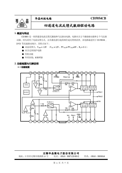
CD595
-50 0 50
3.6 4.0
13.5 15.5 17.5
0
1
2
待机工作电流 待机工作电压 待机关断电压
IST VSTON VSTOFF
0.5
0
0.5
2.0
单位
mA
mA V A/V
V
mA V mA mA mV V dB
mV V dB dB
mA V V
第3页共7页
华晶双极电路
4. 测试线路
CD5954CB
相位 (deg)
第5页共7页
华晶双极电路
6. 应用线路与应用说明
6. 1 应用线路
DSP
CD5954CB
u- COM
进给 聚焦 循迹 偏压 待机 主轴
100pF
28 27 26 25 24 23 22
10k
待机 热保护
7.5k 20k
7.5k
2 检测放大
7.5k
检测放大 2
20k
7.5k 10k
1234567
8 4
2
1
0
-1
-2
-3
-4
-5
-2 -1 0
1
2
输入电压 V IN (V)
进给驱动器前级运放频率特性
10k
60
+
180
-
20k
40
90
g
100
Vin
20
0
0
Vcc=12V, -20 PVcc1=
PVcc2=5V
10k
ห้องสมุดไป่ตู้
100k
1M
频率 f (Hz)
-90 -180 10M
FLM5964-4F中文资料
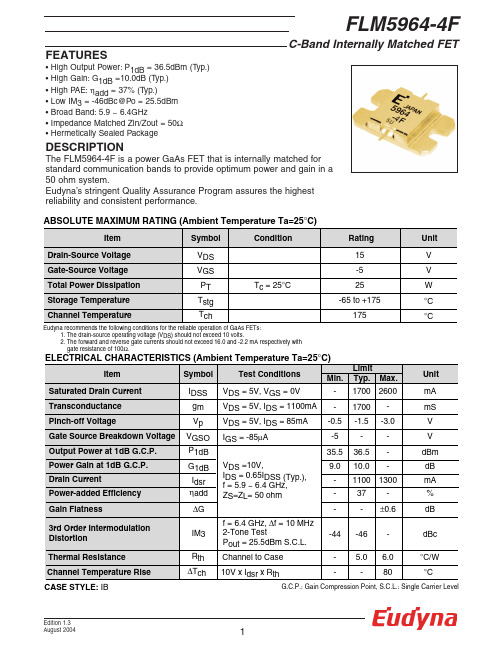
PT
Tc = 25°C
25
W
Storage Temperature
Tstg
-65 to +175
°C
Channel Temperature
Tch
175
°C
Eudyna recommends the following conditions for the reliable operation of GaAs FETs: 1. The drain-source operating voltage (VDS) should not exceed 10 volts. 2. The forward and reverse gate currents should not exceed 16.0 and -2.2 mA respectively with gate resistance of 100Ω.
.277
42.8
.310
25.2
.331
7.3
.335
-12.1
.328
-34.9
.320
-61.6
.324
-92.2
S-PARAMETERS
VDS = 10V, IDS = 1100mA
S21
S12
MAG ANG
MAG ANG
4.092 4.126 4.138 4.131 4.095 4.056 4.000 3.924 3.817 3.664
2355 Zanker Rd. San Jose, CA 95131-1138, U.S.A. TEL: (408) 232-9500 FAX: (408) 428-9111
Eudyna Devices Europe Ltd.
4HC595完整中文资料

74HC595芯片是一种串入并出的芯片,在电子显示屏制作当中有广泛的应用。
74HC595是8位串行输入/输出或者并行输出移位寄存器,具有高阻、关、断状态。
三态。
特点 8位串行输入 8位串行或并行输出存储状态寄存器,三种状态输出寄存器可以直接清除 100MHz的移位频率输出能力并行输出,总线驱动串行输出;标准中等规模集成电路应用串行到并行的数据转换 Remote contr ol holding register. 描述 595是告诉的硅结构的CMOS器件,兼容低电压TTL电路,遵守JEDEC标准。
595是具有8位移位寄存器和一个存储器,三态输出功能。
移位寄存器和存储器是分别的时钟。
数据在SCHcp的上升沿输入,在STcp 的上升沿进入的存储寄存器中去。
如果两个时钟连在一起,则移位寄存器总是比存储寄存器早一个脉冲。
移位寄存器有一个串行移位输入(Ds),和一个串行输出(Q7’),和一个异步的低电平复位,存储寄存器有一个并行8位的,具备三态的总线输出,当使能OE时(为低电平),存储寄存器的数据输出到总线。
CPD决定动态的能耗, PD=CPD×VCC×f1+∑(CL×VCC2×f0) F1=输入频率,CL=输出电容 f0=输出频率(MHz) Vcc=电源电压引脚说明符号引脚描述内部结构结合引脚说明就能很快理解 595的工作情况引脚功能表:管脚编号管脚名管脚定义功能1、2、3、4、5、6、7、15QA—QH 三态输出管脚8 GND 电源地9 SQH 串行数据输出管脚10 SCLR 移位寄存器清零端11 SCK 数据输入时钟线12 RCK 输出存储器锁存时钟线13 OE 输出使能14 SI 数据线15 VCC 电源端真值表:输入管脚输出管脚SI SCK SCLR RCK OEX X X X H QA—QH 输出高阻X X X X L QA—QH 输出有效值X X L X X 移位寄存器清零L 上沿H X X 移位寄存器存储LH 上沿H X X 移位寄存器存储HX 下沿H X X 移位寄存器状态保持X X X 上沿X 输出存储器锁存移位寄存器中的状态值X X X 下沿X 输出存储器状态保持74595的数据端:QA--QH: 八位并行输出端,可以直接控制数码管的8个段。
74HC595完整中文资料word资料5页
74HC595芯片是一种串入并出的芯片,在电子显示屏制作当中有广泛的应用。
74HC595是8位串行输入/输出或者并行输出移位寄存器,具有高阻、关、断状态。
三态。
特点 8位串行输入 8位串行或并行输出存储状态寄存器,三种状态输出寄存器可以直接清除 100MHz的移位频率输出能力并行输出,总线驱动串行输出;标准中等规模集成电路应用串行到并行的数据转换 Remote contr ol holding register. 描述 595是告诉的硅结构的CMOS器件,兼容低电压TTL电路,遵守JEDEC标准。
595是具有8位移位寄存器和一个存储器,三态输出功能。
移位寄存器和存储器是分别的时钟。
数据在SCHcp的上升沿输入,在STcp 的上升沿进入的存储寄存器中去。
如果两个时钟连在一起,则移位寄存器总是比存储寄存器早一个脉冲。
移位寄存器有一个串行移位输入(Ds),和一个串行输出(Q7’),和一个异步的低电平复位,存储寄存器有一个并行8位的,具备三态的总线输出,当使能OE时(为低电平),存储寄存器的数据输出到总线。
CPD决定动态的能耗, PD=CPD×VCC×f1+∑(CL×VCC2×f0) F1=输入频率,CL=输出电容 f0=输出频率(MHz) Vcc=电源电压引脚说明符号引脚描述内部结构结合引脚说明就能很快理解 595的工作情况引脚功能表:管脚编号管脚名管脚定义功能1、2、3、4、5、6、7、15QA—QH 三态输出管脚8 GND 电源地9 SQH 串行数据输出管脚10 SCLR 移位寄存器清零端11 SCK 数据输入时钟线12 RCK 输出存储器锁存时钟线13 OE 输出使能14 SI 数据线15 VCC 电源端真值表:输入管脚输出管脚SI SCK SCLR RCK OEX X X X H QA—QH 输出高阻X X X X L QA—QH 输出有效值X X L X X 移位寄存器清零L 上沿H X X 移位寄存器存储LH 上沿H X X 移位寄存器存储HX 下沿H X X 移位寄存器状态保持X X X 上沿X 输出存储器锁存移位寄存器中的状态值X X X 下沿X 输出存储器状态保持74595的数据端:QA--QH: 八位并行输出端,可以直接控制数码管的8个段。
FLM5964-12F中文资料

FEATURES• High Output Power:P 1dB = 41.5dBm (Typ.)• High Gain:G 1dB = 10.0dB (Typ.)• High PAE:ηadd = 37% (Typ.)• Low IM 3= -46dBc@Po = 30.5dBm • Broad Band:5.9 ~ 6.4GHz• Impedance Matched Zin/Zout = 50Ω • Hermetically Sealed PackageC-Band Internally Matched FETEudyna recommends the following conditions for the reliable operation of GaAs FETs:1. The drain-source operating voltage (V DS ) should not exceed 10 volts.2. The forward and reverse gate currents should not exceed 32.0 and -5.6 mA respectively with gate resistance of 50Ω.DESCRIPTIONThe FLM5964-12F is a power GaAs FET that is internally matched for standard communication bands to provide optimum power and gain in a 50 ohm system.Eudyna ’s stringent Quality Assurance Program assures the highest reliability and consistent performance.G.C.P.: Gain Compression Point, S.C.L.: Single Carrier LevelCASE STYLE: IKC-Band Internally Matched FETPOWER DERATING CURVE500100150200Case Temperature (°C)60453015T o t a l P o w e r D i s s i p a t i o n (W)OUTPUT POWER & IM 3 vs. INPUT POWERV DS =10V f 1 = 6.4 GHz f 2 = 6.41 GHz 2-tone test15171921232527Input Power (S.C.L.) (dBm)S.C.L.: Single Carrier Level272931333735252321-55-50-45-40-35-30-25-20O u t p u t P o w e r (S .C .L .) (d B m )IM 3P outI M 3 (d B c )OUTPUT POWER vs. FREQUENCYPin=32.5dBm28.5dBm 26.5dBm30.5dBm6.05.96.16.36.26.4Frequency (GHz)3839404142434437O u t p u t P o w e r (d B m )V DS =10V P 1dBOUTPUT POWER vs. INPUT POWERV DS =10V f = 6.15 GHz20222426283032Input Power (dBm)424440383634323020304050100O u t p u t P o w e r (d B m )ηaddP outηa d d (%)C-Band Internally Matched FETS-PARAMETERSV DS= 10V, I DS= 3250mAFREQUENCY S11S21S12S22 (MHZ)MAG ANG MAG ANG MAG ANG MAG ANG5700.45551.2 3.642-107.3.056-140.50.496140.45800.41134.8 3.713-123.0.060-155.30.493127.15900.35416.2 3.773-139.4.064-171.60.482113.56000.283-7.1 3.824-156.4.067171.70.46599.66100.211-41.1 3.844-174.2.070153.60.43485.96200.181-92.2 3.822167.6.073136.10.40172.56300.234-141.8 3.754148.8.072118.70.35359.06400.335-175.7 3.621129.6.07299.60.29445.66500.442160.5 3.415110.5.06982.60.22435.26600.536140.5 3.17391.5.06564.50.15330.8C-Band Internally Matched FETEudyna Devices Inc. products contain gallium arsenide(GaAs) which can be hazardous to the human body and the environment. For safety, observe the following procedures:CAUTION• Do not put this product into the mouth.• Do not alter the form of this product into a gas, powder, or liquidthrough burning, crushing, or chemical processing as these by-products are dangerous to the human body if inhaled, ingested, or swallowed.• Observe government laws and company regulations when discarding this product. This product must be discarded in accordance with methods specified by applicable hazardous waste procedures.For further information please contact:Eudyna Devices USA Inc.2355 Zanker Rd.San Jose, CA 95131-1138, U.S.A.TEL:(408) 232-9500FAX:(408) 428-9111Eudyna Devices Europe Ltd.Network House Norreys DriveMaidenhead, Berkshire SL6 4FJ United KingdomTEL:+44 (0) 1628 504800FAX:+44 (0) 1628 504888Eudyna Devices Asia Pte Ltd.Hong Kong BranchRm.1101, Ocean Centre, 5 Canton Rd.Tsim Sha Tsui, Kowloon, Hong Kong TEL:+852-2377-0227FAX:+852-2377-3921Eudyna Devices Inc.Sales Division1, Kanai-cho, Sakae-kuY okohama, 244-0845, Japan TEL:+81-45-853-8156FAX:+81-45-853-8170Eudyna Devices Inc.reserves the right to change products and specifications without notice.The information does not convey any license under rights of Eudyna Devices Inc.or others.©2004 Eudyna Devices USA Inc.Printed in U.S.A.。
74HC595芯片资料
74HC595芯片资料8位串行输入/输出或者并行输出移位寄存器,具有高阻关断状态。
三态。
特点8位串行输入8位串行或并行输出存储状态寄存器,三种状态输出寄存器可以直接清除100MHz的移位频率输出能力并行输出,总线驱动串行输出;标准中等规模集成电路应用串行到并行的数据转换Remote control holding register.描述595是告诉的硅结构的CMOS器件,兼容低电压TTL电路,遵守JEDEC标准。
595是具有8位移位寄存器和一个存储器,三态输出功能。
移位寄存器和存储器是分别的时钟。
数据在SCHcp的上升沿输入,在STcp的上升沿进入的存储寄存器中去。
如果两个时钟连在一起,则移位寄存器总是比存储寄存器早一个脉冲。
移位寄存器有一个串行移位输入(Ds),和一个串行输出(Q7’),和一个异步的低电平复位,存储寄存器有一个并行8位的,具备三态的总线输出,当使能OE时(为低电平),存储寄存器的数据输出到总线。
参考数据CPD决定动态的能耗,PD=CPD×VCC×f1+∑(CL×VCC2×f0)F1=输入频率,CL=输出电容f0=输出频率(MHz)Vcc=电源电压功能表H=高电平状态L=低电平状态↑=上升沿↓=下降沿Z=高阻NC=无变化×=无效当MR为高电平,OE为低电平时,数据在SHCP上升沿进入移位寄存器,在STCP上升沿输出到并行端口。
/***************************************************************************************/ 给个74HC595的"慢动作"void WriteSIOByte(unsigned char val){unsigned char i;ACC = val;for (i = 8; i > 0; i --) {SRCLK = 0;//拉低74HC595时钟_rrca_();//右移一位数据SER = CY;//发送74HC595一位串行数据SRCLK = 1;//拉高74HC595时钟_nop_();//延时}SER = 1;//释放数据总线//以下3条指令若在多字节时,应该移入多字节全发送完后在执行此3条指令RCLK = 0;_nop_();//延时RCLK = 1;//打入并行数据}74ls595"速射"hotpowerfor(i = 0; i < buffsize; i ++){SBUF = siobuff[i];while(TI == 0);TI = 0;}RCLK = 0;_nop_();//延时RCLK = 1;//打入并行数据/************************************************************************/摘要:本文介绍了应用移位寄存器芯片74HC595实现LED动、静态显示的基本原理。
74HC595完整中文资料复习过程
74H C595完整中文资料74HC595芯片是一种串入并出的芯片,在电子显示屏制作当中有广泛的应用。
74HC595是8位串行输入/输出或者并行输出移位寄存器,具有高阻、关、断状态。
三态。
特点 8位串行输入 8位串行或并行输出存储状态寄存器,三种状态输出寄存器可以直接清除 100MHz的移位频率输出能力并行输出,总线驱动串行输出;标准中等规模集成电路应用串行到并行的数据转换 Remote contr ol holding register. 描述 595是告诉的硅结构的CMOS器件,兼容低电压TTL电路,遵守JEDEC标准。
595是具有8位移位寄存器和一个存储器,三态输出功能。
移位寄存器和存储器是分别的时钟。
数据在SCHcp的上升沿输入,在ST cp的上升沿进入的存储寄存器中去。
如果两个时钟连在一起,则移位寄存器总是比存储寄存器早一个脉冲。
移位寄存器有一个串行移位输入(Ds),和一个串行输出(Q7’),和一个异步的低电平复位,存储寄存器有一个并行8位的,具备三态的总线输出,当使能OE时(为低电平),存储寄存器的数据输出到总线。
CPD决定动态的能耗, PD=CPD×VCC×f1+∑(CL×VCC2×f0) F1=输入频率,CL=输出电容 f0=输出频率(MHz) Vcc=电源电压引脚说明符号引脚描述内部结构结合引脚说明就能很快理解 595的工作情况引脚功能表:真值表:QA--QH: 八位并行输出端,可以直接控制数码管的8个段。
QH': 级联输出端。
我将它接下一个595的SI端。
SI: 串行数据输入端。
74595的控制端说明:/SRCLR(10脚): 低点平时将移位寄存器的数据清零。
通常我将它接Vcc。
SRCK(11脚):上升沿时数据寄存器的数据移位。
QA-->QB-->QC-->...-->QH;下降沿移位寄存器数据不变。
(脉冲宽度:5V时,大于几十纳秒就行了。
BA5954FP中文资料

Current feedback actuator driver
BA5954FP/FM
Description BA5954FP/FM is an actuator driver IC for CD-ROM and DVD players. This actuator driver adopts current feedback system. This IC incorporates 2 channel actuator drivers and 2 channel motor drivers. Current phase lag influenced load inductance is little, because this type is current feedback. Dimension (Units : mm)
0.11
0.1 S
HSOP28 / HSOP-M28
Applications CD/CD-ROM Absolute Maximum Ratings (Ta=25˚C)
Parameter Supply voltage Power dissipation Operating temperature range Storage temperature range
This product is not designed for protection against radioactive rays.
Application Circuit
DSP
Stand-by Tracking Loading Vcenter
µ - COM
Focus
Sled
Tracking Coil 5Vor12V Rd
74HC595完整中文资料

74HC595芯片是一种串入并出的芯片,在电子显示屏制作当中有广泛的应用。
74HC595是8位串行输入/输出或者并行输出移位寄存器,具有高阻、关、断状态。
三态。
特点 8位串行输入 8位串行或并行输出存储状态寄存器,三种状态输出寄存器可以直接清除 100MHz的移位频率输出能力并行输出,总线驱动串行输出;标准中等规模集成电路应用串行到并行的数据转换 Remote contr ol holding register. 描述 595是告诉的硅结构的CMOS器件,兼容低电压TTL电路,遵守JEDEC标准。
595是具有8位移位寄存器和一个存储器,三态输出功能。
移位寄存器和存储器是分别的时钟。
数据在SCHcp的上升沿输入,在STcp 的上升沿进入的存储寄存器中去。
如果两个时钟连在一起,则移位寄存器总是比存储寄存器早一个脉冲。
移位寄存器有一个串行移位输入(Ds),和一个串行输出(Q7’),和一个异步的低电平复位,存储寄存器有一个并行8位的,具备三态的总线输出,当使能OE时(为低电平),存储寄存器的数据输出到总线。
CPD决定动态的能耗, PD=CPD×VCC×f1+∑(CL×VCC2×f0) F1=输入频率,CL=输出电容 f0=输出频率(MHz) Vcc=电源电压引脚说明符号引脚描述内部结构结合引脚说明就能很快理解 595的工作情况引脚功能表:真值表:74595的控制端说明:/SRCLR(10脚): 低点平时将移位寄存器的数据清零。
通常我将它接Vcc。
SCK(11脚):上升沿时数据寄存器的数据移位。
QA-->QB-->QC-->...-->QH;下降沿移位寄存器数据不变。
(脉冲宽度:5V时,大于几十纳秒就行了。
我通常都选微秒级)RCK(12脚):上升沿时移位寄存器的数据进入数据存储寄存器,下降沿时存储寄存器数据不变。
(通常我将RCK置为低电平,) 当移位结束后,在RCK端产生一个正脉冲(5V时,大于几十纳秒就行了。
74VHC595MX资料

s High Speed: tPD = 5.4 ns (typ) at VCC = 5V s Low power dissipation: ICC = 4 µA (max) at TA = 25°C s High noise immunity: VNIH = VNIL = 28% VCC (min) s Power down protection is provided on all inputs s Low noise: VOLP = 0.9V (typ) s Pin and function compatible with 74HC595
Pin Names
Description
SER
Serial Data Input
SCK
Shift Register Clock Input (Active rising edge)
RCK
Storage Register Clock Input (Active rising edge)
SCLR
Reset Input
Note 2: Unused inputs must be held HIGH or LOW. They may not float.
DC Electrical Characteristics
Symbol VIH VIL VOH
VOL
IOZ
IIN ICC
Parameter
VCC
(V)
HIGH Level
2.0
Input Voltage
3.0 − 5.5
LOW Level
2.0
Input Voltage
3.0 − 5.5
HIGH Level
பைடு நூலகம்2.0
BA5954FP中文资料

Appendix1-Rev1.1
Contact us
Attached-1
Thank you for your accessing to ROHM product informations. More detail product informations and catalogs are available, please contact your nearest sales office.
The products listed in this document are designed to be used with ordinary electronic equipment or devices (such as audio visual equipment, office-automation equipment, communications devices, electrical appliances and electronic toys). Should you intend to use these products with equipment or devices which require an extremely high level of reliability and the malfunction of with would directly endanger human life (such as medical instruments, transportation equipment, aerospace machinery, nuclear-reactor controllers, fuel controllers and other safety devices), please be sure to consult with our sales representative in advance. About Export Control Order in Japan Products described herein are the objects of controlled goods in Annex 1 (Item 16) of Export Trade Control Order in Japan. In case of export from Japan, please confirm if it applies to "objective" criteria or an "informed" (by MITI clause) on the basis of "catch all controls for Non-Proliferation of Weapons of Mass Destruction.
D5954中文资料
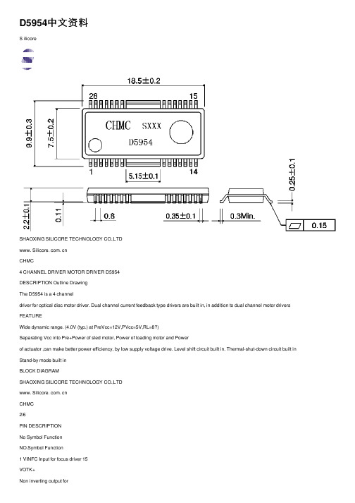
D5954中⽂资料S ilicoreSHAOXING SILICORE TECHNOLOGY CO.,LTDwww. Silicore. com. cnCHMC4 CHANNEL DRIVER MOTOR DRIVER D5954DESCRIPTION Outline DrawingThe D5954 is a 4 channeldriver for optical disc motor driver. Dual channel current feedback type drivers are built in, in addition to dual channel motor drivers FEATUREWide dynamic range. (4.0V (typ.) at PreVcc=12V,PVcc=5V,RL=8?)Separating Vcc into Pre+Power of sled motor, Power of loading motor and Powerof actuator ,can make better power efficiency, by low supply voltage drive. Level shift circuit built in. Thermal-shut-down circuit built in Stand-by mode built inBLOCK DIAGRAMSHAOXING SILICORE TECHNOLOGY CO.,LTDwww. Silicore. com. cnCHMC2/6PIN DESCRIPTIONNo Symbol FunctionNO.Symbol Function1 VINFC Input for focus driver 15VOTK+Non inverting output for2CECerr116VOTK-Inverting output for tracking3 CECerr2 Connection with capacitor for error amplifier 17OLD+Non inverting output forloading 4 VINSL + Non inverting input forOP-amp18VOLD-Inverting output for loading 5 VINSL- Inverting input for OP-amp 19PGNDGND for power block6 VOSLOutput of OP-amp20VNFTK Feedback for tracking driver7VNFFC Feedback for focus driver21PVcc2Vcc for power block ofactuator8 Vcc Vcc for pre-driver blockand power block of sled 22PreGND GND for pre-drive block9 PVcc1 Vcc for power block ofloading23VINLD Input for loading driver10 PGND GND for power block 24CTKerr211 VOSL- Inverting output for sled 25CTKerr1Connection with capacitor for error amplifier 12 VOSL+ Non inverting output for sled26VINTK Input for tracking driver 13 VOFC- Inverting output for focus 27BIAS Input for reference voltage 14 VOFC+ Non inverting output forfocus28STBYInput for stand-by controlABSOLUTE MAXIMUM RATINGS (Ta=25°C)Characteristic Symbol Value UnitSupply voltage Vcc 13.5 V Power dissipation PD 1.7* W Operating temperature Topr -35~85 °C Storage TemperatureTstg-40~150°C* On less than 3%(percentage occupied by copper foil), 70×70mm 2, t=1.6mm, glass epoxy mounting. Reduce power by 13.6mW for each degree above 25°CSHAOXING SILICORE TECHNOLOGY CO.,LTD www. Silicore. com. cnGUARANTEED OPERATING RANGESParameter Symbol Limits UnitVcc 4.3~13.2PVcc1 4.3~Vcc Supply voltagePVcc2 4.3~VccVELECTRICAL CHARACTERISTICS(unless otherwise specified: Ta=25°C, Vcc=12V,PVcc1=PVcc2=5V,BIAS=2.5V,R L=8?, Rd=0.5?, C=100pF)Characteristics TestconditionsSymbol MinTypMaxUnit Quiescent current Icc 18 27 mA Stand-by quiescent current Isc 0.5 mA Voltage for stand-by ON V S TO N0.5V Voltage for stand-by OFF V S TO F F 2.0 V< Actuator driver >Output offset current Ico -6 6 mA Maximum output voltage Vc M 3.6 4.0 V Trans conductance V I N=BIAS±0.2V gm 1.3 1.5 1.7A/V< Sled motor driver/ Pre OP-amp >Common mode input range V I C M -0.3 11.0 V Input bias current I B O P30300nALow level output voltage V O L O P 0.1 0.3 V Output source current I S O 0.3 0.5 mA Output sink current I S T 1 mA< Sled motor driver >Output offset voltage V O O F S L-100 0 100 mV Maximum output voltage V O M S L7.5 9.0 V Closed loop voltage gain V I N=±0.2V G V S L 18 20 22 dB< Loading motor driver>Output offset voltage V O O F L D-50 0 50 mV Maximum output voltage V O M L D 3.6 4.0 V Closed loop voltage gain V I N=BIAS±0.2V G V L D 13.5 15.5 17.5 dBGain error by polarity V I N=BIAS±0.2V ?G V L D0 1 2 dBTEST CIRCUITSWITCH TABLEwww. Silicore. com. cnCHMCSHAOXING SILICORE TECHNOLOGY CO.,LTD www. Silicore. com. cnCHMC 5/6SWITCH TABLE continueInput voltage Characteristics SWVIN1VIN2VIN3VIN4VST ConditionsMeasurepoint< Sled motor driver >Input bias current 2 2.5V 2.5V 2.5V 2.5V 5.0V VBOP/1M Low level output voltage 1 2.5V 2.5V0V 2.5V 5.0V Voop Output source current 1 2.5V 2.5V 2.5V 2.5V 5.0V Ioop=+0.2mA VoopOutput sink current 1 2.5V 2.5V 2.5V 2.5V 5.0V Ioop=-1mA VoopOutput offset voltage 1 2.5V 2.5V 2.5V 2.5V 5.0V Vo3Maximum output voltage 1 2.5V 2.5V 0V5V2.5V 5.0V Vo3Closed loop voltage gain 1 2.5V 2.5V 2.3V2.7V2.5V 5.0V Vo3APPLICATION CIRCUITSHAOXING SILICORE TECHNOLOGY CO.,LTD www. Silicore. com. cnCHMC 6/6NOTES ON USE1. Thermal-shut-down circuit built-in. In case IC chip temperature rise to175°C(typ.), thermal-shut-down circuit operates and output current is muted. Next time IC chip temperature falls bellows 150°C(typ.), the driver blocks start.2. In case stand-by-pin voltage under 0.5V or opened, quiescent current is muted.Stand-by-pin voltage should be over 2.0V for normal application.3. In case supply voltage falls below 3.5V (typ.), output current is muted. Next timesupply voltage rises to 3.7V(typ.), the driver blocks start.4. Bias\pin (pin27) should be pulled up more than 1.2V. In case bias-pin voltage ispulled down under 0.9V (typ.), output current is muted.5. Insert the by-pass capacitor between Vcc-pin and GND-pin of IC as possible asnear (approximately 0.1µF).6. Heat dissipation fins are attached to the GND on the inside of the package. Makesure to connect these to the external GND.7. Output pin is to avoid short-circuit with Vcc, GND and other output pins.And, be fully careful in the direction of an integrated circuit when you put an integrated circuit.On the substrate. An integrated circuit is damaged, and smoke may come out by the case.※Output pin …11~18pin Vcc…8pin, PVcc1…9pin, PVcc2…21pinPreGND…22pin, PGND…10,19pinCHARACTERISTIC CURVESAmbient temperature Ta (°C) Pd: power dissipation * On less than 3%(percentage occupied by copper foil), 70×70mm2, t=1.6mm, glass epoxy mounting.。
IP5954A-TF中文资料
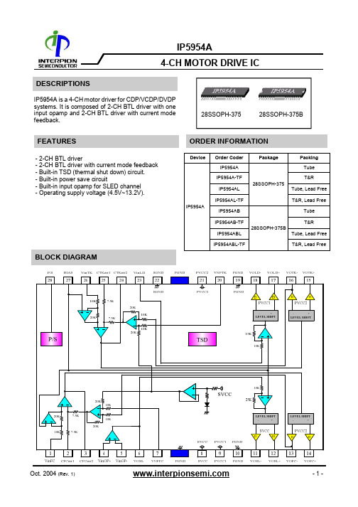
4-CH MOTOR DRIVE IC- 2-CH BTL driver- 2-CH BTL driver with current mode feedback - Built-in TSD (thermal shut down) circuit. - Built-in power save circuit- Built-in input opamp for SLED channel - Operating supply voltage (4.5V~13.2V).IP5954A is a 4-CH motor driver for CDP/VCDP/DVDP systems. It is composed of 2-CH BTL driver with one input opamp and 2-CH BTL driver with current mode feedback.DESCRIPTIONSBLOCK DIAGRAMORDER INFORMATIONFEATURES28SSOPH-375 DeviceOrder Coder PackagePacking IP5954A 28SSOPH-375 Tube IP5954A-TF T&R IP5954AL Tube, Lead Free IP5954AL-TFT&R, Lead FreeIP5954AB 28SSOPH-375BTube IP5954AB-TFT&RIP5954ABL Tube, Lead Free IP5954ABL-TFT&R, Lead FreeIP5954A28SSOPH-375B4-CH MOTOR DRIVE ICPIN DESCRIPTIONSPIN CONNECTIONSNO SYMBOL I/ODESCRIPTION 1VinFCI Focus input2 CFCerr1- Error amp filter connection 1 for focus actuator3 CFCerr2 -Error amp filter connection 2 for focus actuator 4 VinOP+I OPamp IN(+) for sled driver 5 VinOP- IOPamp IN(-) for sled driver6 VOSL O OPamp out for sled driver7 VNFFC ICurrent feedback pin for focus actuator8 SVCC- Signal supply voltage9 PVCC1- Power supply voltage 110 PGND -Power ground11VOSL- OSled driver output(-) 12VOSL+ OSled driver output(+) 13VOFC- OFocus driver output(-) 14VOFC+OFocus driver output(+)NOSYMBOLI/O DESCRIPTION 15VOTK+ O Tracking driver output(+) 16 VOTK- O Tracking driver output(-) 17VOLD+ O Loading driver output(+) 18 VOLD- O Loading driver output(-) 19 PGND - Power Ground20 VNFTK I Current feedback pin for Tracking actuator 21 PVCC2 - Power supply voltage 2 22 SGND - Signal ground 23 VinLD I Loading input24 CTKerr2 - Error amp filter connection 2 for Tracking actuator 25 CTKerr1 - Error amp filter connection 1 for Tracking actuator 26 VinTK I Tracking input 27 BIAS IBias input28P/SO Power save4-CH MOTOR DRIVE ICCHARACTERISTICS SYMBOL VALUE UNIT Maximum supply voltageVCCmax 15 V Power dissipation Pd28SSOPH-3751.7W28SSOPH-375B 2.3 WOperating temperature Topr -35 ~ +85 OC Storage temperature-55 ~ 150OCTstgNote>1. When mounted on 70mm X 70mm X 1.6mm PCB (Phenolic resin material).2. Power dissipation reduces 13.6 mW/O C for using above Ta=25O C 3. Do not exceed Pd and SOA.POWER DISSIPATION CURVERECOMMENDED OPERATING CONDITIONSCHARACTERISTICS SYMBOL VALUE UNIT Signal supply Voltage VCC1 4.5 ~ 13.2 V Power supply Voltage 2PVCC24.5 ~ 13.2VPower supply Voltage 1 PVCC1 4.5 ~ 13.2 V ABSOLUTE MAXIMUM RATINGSP o w e r D i s s i p a t i o n (m W )Ambient Temperature (°C )25 50 75 100 125 150 1750 12 3P o w e r D i s s i p a t i o n (m W )Ambient Temperature (°C )25 50 75 100 125 150 1750 12 3 28SSOPH-37528SSOPH-375B4-CH MOTOR DRIVE ICELECTRICAL CHARACTERISTICS(SVCC=8.0V,PVCC1=PVCC2=5V, f = 1kHz, RL=12ohm, Rs=0.5ohm, Ta = 25O C unless otherwise specified.) CHARACTERISTICS SYMBOL CONDITIONS MIN TYP MAX UNIT Quiescent circuit current Icc No Load-14-mA Power save on current Ips Pin28=GND--1mA Power save on voltage Vmon Pin28=variation--0.5V Power save off voltage Vmoff Pin28=variation 2.0--V Reference mute on voltage Vrmon Pin27=variation--0.7V Reference mute off voltage Vrmoff Pin27=variation 1.3--V [ ACTUATOR DRIVE PART ]Output offset current Iooa Pin1=Pin9=Pin22=Vref -15015mA Maximum output voltage Voma - 3.6 4.0-V Transmission gain 45 Gma Vin=0.1Vrms, f=1kHz- 1.5-A/V [ LOADING DRIVE PART ]Output offset voltage Vool Vin=Vref -80-+80mV Maximum output voltage Voml - 3.6 4.0-V Closed-loop voltage gain Avfl Vin=0.1Vrms, f=1kHz13.515.517.5dB Slew rate SRl Vout = 4.0Vpp, Square- 1.5-V/usec Ripple rejection ratio RRl Vin=0.1Vrms, f=120Hz5060-dB4-CH MOTOR DRIVE ICELECTRICAL CHARACTERISTICS (Continued)CHARACTERISTICS SYMBOL CONDITIONS MIN TYP MAX UNIT [ SLED DRIVE INPUT OPAMP PART ]Common mode input range Vicm Vbias=4.0V -0.3-7.0V Input bias current Ib -30300nA Low level output voltage Vol -0.10.3V Output source current Isrc -0.20.5-mA Output sink current Isnk -1--mA [ SLED DRIVE PART ]Output offset voltage Voos Vin=Vref -100-+100mVMaximum output voltage Voms SVCC=8.0V,PVCC1=PVCC2=5V, RL=12ohm- 6.0-VClosed-loop voltage gain Avfs Vin=0.1Vrms, f=1kHz182022dB Slew rate SRs Vout = 4.0Vpp, Square- 1.5-V/usec Ripple rejection ratio RRs Vin=0.1Vrms, f=120Hz5060-dB (SVCC=8.0V,PVCC1=PVCC2=5V, f = 1kHz, RL=12ohm, Rs=0.5ohm, Ta = 25O C unless otherwise specified.)4-CH MOTOR DRIVE IC TYPICAL APPLICATION CIRCUIT4-CH MOTOR DRIVE ICINTERNAL CIRCUITPin noPin nameInternal circuit1,23, 26,27VinFC, VinLD, VinTK, Bias2, 7, 20, 25CFCerr1, VNFFC, VNFTK, CTKerr13, 24CFCerr2, CTKerr227126234-CH MOTOR DRIVE ICINTERNAL CIRCUIT (Continued)Pin noPin nameInternal circuit4,5VinOP+, VinOP-28PS11, 12, 13, 14, 15, 16, 17, 18VOSL- VOSL+ VOFC- VOFC+ VOTK+ VOTK- VOLD+ VOLD-4-CH MOTOR DRIVE IC PACKAGE DIMENSION28SSOPH-3754-CH MOTOR DRIVE IC28SSOPH-375BPACKAGE DIMENSION (Continued)。
SN74AHC595PWRE4中文资料

PACKAGING INFORMATIONOrderable Device Status (1)Package Type Package DrawingPins Package Qty Eco Plan (2)Lead/Ball Finish MSL Peak Temp (3)SN74AHC595D ACTIVE SOIC D 1640Green (RoHS &no Sb/Br)CU NIPDAU Level-1-260C-UNLIM SN74AHC595DBR ACTIVE SSOP DB 162000Green (RoHS &no Sb/Br)CU NIPDAU Level-1-260C-UNLIM SN74AHC595DBRE4ACTIVE SSOP DB 162000Green (RoHS &no Sb/Br)CU NIPDAU Level-1-260C-UNLIM SN74AHC595DBRG4ACTIVE SSOP DB 162000Green (RoHS &no Sb/Br)CU NIPDAULevel-1-260C-UNLIM SN74AHC595DE4ACTIVE SOIC D 1640Green (RoHS &no Sb/Br)CU NIPDAU Level-1-260C-UNLIM SN74AHC595DG4ACTIVE SOIC D 1640Green (RoHS &no Sb/Br)CU NIPDAU Level-1-260C-UNLIM SN74AHC595DR ACTIVE SOIC D 162500Green (RoHS &no Sb/Br)CU NIPDAU Level-1-260C-UNLIM SN74AHC595DRE4ACTIVE SOIC D 162500Green (RoHS &no Sb/Br)CU NIPDAU Level-1-260C-UNLIM SN74AHC595DRG4ACTIVE SOIC D 162500Green (RoHS &no Sb/Br)CU NIPDAU Level-1-260C-UNLIM SN74AHC595N ACTIVE PDIP N 1625Pb-Free (RoHS)CU NIPDAU N /A for Pkg Type SN74AHC595NE4ACTIVE PDIP N 1625Pb-Free (RoHS)CU NIPDAU N /A for Pkg Type SN74AHC595NSR ACTIVE SO NS 162000Green (RoHS &no Sb/Br)CU NIPDAU Level-1-260C-UNLIM SN74AHC595NSRE4ACTIVE SO NS 162000Green (RoHS &no Sb/Br)CU NIPDAU Level-1-260C-UNLIM SN74AHC595NSRG4ACTIVE SO NS 162000Green (RoHS &no Sb/Br)CU NIPDAU Level-1-260C-UNLIM SN74AHC595PW ACTIVE TSSOP PW 1690Green (RoHS &no Sb/Br)CU NIPDAU Level-1-260C-UNLIM SN74AHC595PWE4ACTIVE TSSOP PW 1690Green (RoHS &no Sb/Br)CU NIPDAU Level-1-260C-UNLIM SN74AHC595PWG4ACTIVE TSSOP PW 1690Green (RoHS &no Sb/Br)CU NIPDAU Level-1-260C-UNLIM SN74AHC595PWR ACTIVE TSSOP PW 162000Green (RoHS &no Sb/Br)CU NIPDAU Level-1-260C-UNLIM SN74AHC595PWRE4ACTIVE TSSOP PW 162000Green (RoHS &no Sb/Br)CU NIPDAU Level-1-260C-UNLIM SN74AHC595PWRG4ACTIVETSSOPPW162000Green (RoHS &no Sb/Br)CU NIPDAULevel-1-260C-UNLIM(1)The marketing status values are defined as follows:ACTIVE:Product device recommended for new designs.LIFEBUY:TI has announced that the device will be discontinued,and a lifetime-buy period is in effect.NRND:Not recommended for new designs.Device is in production to support existing customers,but TI does not recommend using this part in a new design.PREVIEW:Device has been announced but is not in production.Samples may or may not be available.OBSOLETE:TI has discontinued the production of the device.(2)Eco Plan -The planned eco-friendly classification:Pb-Free (RoHS),Pb-Free (RoHS Exempt),or Green (RoHS &no Sb/Br)-please check /productcontent for the latest availability information and additional product content details.PACKAGE OPTION ADDENDUM4-Jun-2007Addendum-Page 1TBD:The Pb-Free/Green conversion plan has not been defined.Pb-Free (RoHS):TI's terms "Lead-Free"or "Pb-Free"mean semiconductor products that are compatible with the current RoHS requirements for all 6substances,including the requirement that lead not exceed 0.1%by weight in homogeneous materials.Where designed to be soldered at high temperatures,TI Pb-Free products are suitable for use in specified lead-free processes.Pb-Free (RoHS Exempt):This component has a RoHS exemption for either 1)lead-based flip-chip solder bumps used between the die and package,or 2)lead-based die adhesive used between the die and leadframe.The component is otherwise considered Pb-Free (RoHS compatible)as defined above.Green (RoHS &no Sb/Br):TI defines "Green"to mean Pb-Free (RoHS compatible),and free of Bromine (Br)and Antimony (Sb)based flame retardants (Br or Sb do not exceed 0.1%by weight in homogeneous material)(3)MSL,Peak Temp.--The Moisture Sensitivity Level rating according to the JEDEC industry standard classifications,and peak solder temperature.Important Information and Disclaimer:The information provided on this page represents TI's knowledge and belief as of the date that it is provided.TI bases its knowledge and belief on information provided by third parties,and makes no representation or warranty as to the accuracy of such information.Efforts are underway to better integrate information from third parties.TI has taken and continues to take reasonable steps to provide representative and accurate information but may not have conducted destructive testing or chemical analysis on incoming materials and chemicals.TI and TI suppliers consider certain information to be proprietary,and thus CAS numbers and other limited information may not be available for release.In no event shall TI's liability arising out of such information exceed the total purchase price of the TI part(s)at issue in this document sold by TI to Customer on an annualbasis.PACKAGE OPTION ADDENDUM4-Jun-2007TAPE AND REEL BOXINFORMATIONDevicePackage Pins SiteReel Diameter (mm)Reel Width (mm)A0(mm)B0(mm)K0(mm)P1(mm)W (mm)Pin1Quadrant SN74AHC595DBR DB 16SITE 41330168.2 6.6 2.51216Q1SN74AHC595DR D 16SITE 2733016 6.510.3 2.1816Q1SN74AHC595DR D 16SITE 4133016 6.510.3 2.1816Q1SN74AHC595NSR NS 16SITE 41330168.210.5 2.51216Q1SN74AHC595PWRPW16SITE 41330127.05.61.6812Q14-Oct-2007DevicePackage Pins Site Length (mm)Width (mm)Height (mm)SN74AHC595DBR DB 16SITE 41346.0346.033.0SN74AHC595DR D 16SITE 27342.9336.628.58SN74AHC595DR D 16SITE 41346.0346.033.0SN74AHC595NSR NS 16SITE 41346.0346.033.0SN74AHC595PWRPW16SITE 41346.0346.029.04-Oct-2007IMPORTANT NOTICETexas Instruments Incorporated and its subsidiaries(TI)reserve the right to make corrections,modifications,enhancements, improvements,and other changes to its products and services at any time and to discontinue any product or service without notice. Customers should obtain the latest relevant information before placing orders and should verify that such information is current and complete.All products are sold subject to TI’s terms and conditions of sale supplied at the time of order acknowledgment.TI warrants performance of its hardware products to the specifications applicable at the time of sale in accordance with TI’s standard warranty.Testing and other quality control techniques are used to the extent TI deems necessary to support this warranty.Except where mandated by government requirements,testing of all parameters of each product is not necessarily performed.TI assumes no liability for applications assistance or customer product design.Customers are responsible for their products and applications using TI components.To minimize the risks associated with customer products and applications,customers should provide adequate design and operating safeguards.TI does not warrant or represent that any license,either express or implied,is granted under any TI patent right,copyright,mask work right,or other TI intellectual property right relating to any combination,machine,or process in which TI products or services are rmation published by TI regarding third-party products or services does not constitute a license from TI to use such products or services or a warranty or endorsement e of such information may require a license from a third party under the patents or other intellectual property of the third party,or a license from TI under the patents or other intellectual property of TI. Reproduction of TI information in TI data books or data sheets is permissible only if reproduction is without alteration and is accompanied by all associated warranties,conditions,limitations,and notices.Reproduction of this information with alteration is an unfair and deceptive business practice.TI is not responsible or liable for such altered rmation of third parties may be subject to additional restrictions.Resale of TI products or services with statements different from or beyond the parameters stated by TI for that product or service voids all express and any implied warranties for the associated TI product or service and is an unfair and deceptive business practice.TI is not responsible or liable for any such statements.TI products are not authorized for use in safety-critical applications(such as life support)where a failure of the TI product would reasonably be expected to cause severe personal injury or death,unless officers of the parties have executed an agreement specifically governing such use.Buyers represent that they have all necessary expertise in the safety and regulatory ramifications of their applications,and acknowledge and agree that they are solely responsible for all legal,regulatory and safety-related requirements concerning their products and any use of TI products in such safety-critical applications,notwithstanding any applications-related information or support that may be provided by TI.Further,Buyers must fully indemnify TI and its representatives against any damages arising out of the use of TI products in such safety-critical applications.TI products are neither designed nor intended for use in military/aerospace applications or environments unless the TI products are specifically designated by TI as military-grade or"enhanced plastic."Only products designated by TI as military-grade meet military specifications.Buyers acknowledge and agree that any such use of TI products which TI has not designated as military-grade is solely at the Buyer's risk,and that they are solely responsible for compliance with all legal and regulatory requirements in connection with such use.TI products are neither designed nor intended for use in automotive applications or environments unless the specific TI products are designated by TI as compliant with ISO/TS16949requirements.Buyers acknowledge and agree that,if they use anynon-designated products in automotive applications,TI will not be responsible for any failure to meet such requirements. Following are URLs where you can obtain information on other Texas Instruments products and application solutions:Products ApplicationsAmplifiers Audio /audioData Converters Automotive /automotiveDSP Broadband /broadbandInterface Digital Control /digitalcontrolLogic Military /militaryPower Mgmt Optical Networking /opticalnetworkMicrocontrollers Security /securityRFID Telephony /telephonyLow Power /lpw Video&Imaging /videoWirelessWireless /wirelessMailing Address:Texas Instruments,Post Office Box655303,Dallas,Texas75265Copyright©2007,Texas Instruments Incorporated。
595芯片中文资料
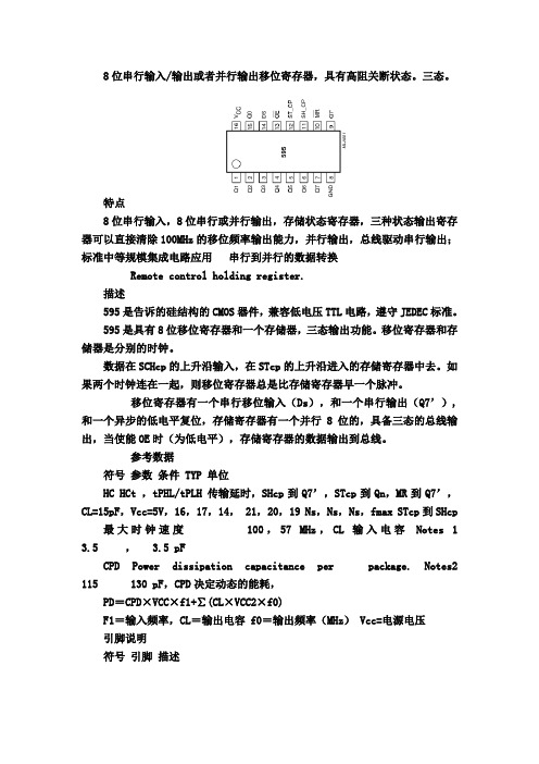
8位串行输入/输出或者并行输出移位寄存器,具有高阻关断状态。
三态。
特点8位串行输入,8位串行或并行输出,存储状态寄存器,三种状态输出寄存器可以直接清除100MHz的移位频率输出能力,并行输出,总线驱动串行输出;标准中等规模集成电路应用串行到并行的数据转换Remote control holding register.描述595是告诉的硅结构的CMOS器件,兼容低电压TTL电路,遵守JEDEC标准。
595是具有8位移位寄存器和一个存储器,三态输出功能。
移位寄存器和存储器是分别的时钟。
数据在SCHcp的上升沿输入,在STcp的上升沿进入的存储寄存器中去。
如果两个时钟连在一起,则移位寄存器总是比存储寄存器早一个脉冲。
移位寄存器有一个串行移位输入(Ds),和一个串行输出(Q7’),和一个异步的低电平复位,存储寄存器有一个并行8位的,具备三态的总线输出,当使能OE时(为低电平),存储寄存器的数据输出到总线。
参考数据符号参数条件 TYP 单位HC HCt ,tPHL/tPLH 传输延时,SHcp到Q7’,STcp到Qn,MR到Q7’,CL=15pF,Vcc=5V,16,17,14, 21,20,19 Ns,Ns,Ns,fmax STcp到SHcp 最大时钟速度100,57 MHz,CL 输入电容Notes 1 3.5 , 3.5 pFCPD Power dissipation capacitance per package. Notes2 115 130 pF,CPD决定动态的能耗,PD=CPD×VCC×f1+∑(CL×VCC2×f0)F1=输入频率,CL=输出电容 f0=输出频率(MHz) Vcc=电源电压引脚说明符号引脚描述Q0…Q7 15, 1, 7 并行数据输出,GND 8 地,Q7’ 9 串行数据输出,MR 10 主复位(低电平),SHCP 11 移位寄存器时钟输入,STCP 12 存储寄存器时钟输入,OE 13 输出有效(低电平),DS 14 串行数据输入,VCC 16 电源功能表输入输出功能SHCP STCP OE MR DS Q7’ Qn× × L ↓ × L NC MR为低电平时紧紧影响移位寄存器× ↑ L L × L L 空移位寄存器到输出寄存器× × H L × L Z 清空移位寄存器,并行输出为高阻状态↑ × L H H Q6’ NC 逻辑高电平移入移位寄存器状态0,包含所有的移位寄存器状态移入,例如,以前的状态6(内部Q6”)出现在串行输出位。
595中文资料
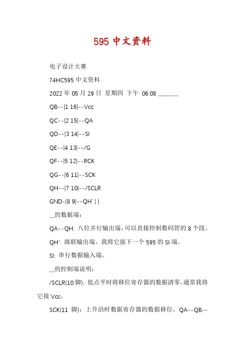
595中文资料电子设计大赛74HC595中文资料2022年05月29日星期四下午06:08 ________QB--|1 16|--VccQC--|2 15|--QAQD--|3 14|--SIQE--|4 13|--/GQF--|5 12|--RCKQG--|6 11|--SCKQH--|7 10|--/SCLRGND-|8 9|--QH' | |__的数据端:QA--QH: 八位并行输出端,可以直接控制数码管的8个段。
QH': 级联输出端。
我将它接下一个595的SI端。
SI: 串行数据输入端。
__的控制端说明:/SCLR(10脚): 低点平时将移位寄存器的数据清零。
通常我将它接Vcc。
SCK(11脚):上升沿时数据寄存器的数据移位。
QA--QB--QC--...--QH;下降沿移位寄存器数据不变。
(脉冲宽度:5V时,大于几十纳秒就行了。
我通常都选微秒级)RCK(12脚):上升沿时移位寄存器的数据进入数据存储寄存器,下降沿时存储寄存器数据不变。
通常我将RCK置为低电平,当移位结束后,在RCK端产生一个正脉冲(5V时,大于几十纳秒就行了。
我通常都选微秒级),更新显示数据。
/G(13脚): 高电平时禁止输出(高阻态)。
如果单片机的引脚不紧张,用一个引脚控制它,可以方便地产生闪烁和熄灭效果。
比通过数据端移位控制要省时省力。
注:__和__功能相仿,都是8位串行输入转并行输出移位寄存器。
__的驱动电流(25mA)比__(35mA)的要小,14脚封装,体积也小一些。
__的主要优点是具有数据存储寄存器,在移位的过程中,输出端的数据可以保持不变。
这在串行速度慢的场合很有用处,数码管没有闪烁感。
与164只有数据清零端相比,595还多有输出端时能/禁止控制端,可以使输出为高阻态。
74HC595是具有8位移位寄存器和一个存储器,三态输出功能。
移位寄存器和存储器是分别的时钟。
数据在SCHcp的上升沿输入,在STcp的上升沿进入的存储寄存器中去。
74HC595完整中文资料
74HC595芯片是一种串入并出的芯片 ,在电子显示屏制作中间有宽泛的应用。
74HC595是8 位串行输入/ 输出或许并行输出移位寄存器,拥有高阻、关、断状态。
三态。
特色8 位串行输入8 位串行或并行输出储存状态寄存器,三种状态输出寄存器能够直接消除 100MHz 的移位频次输出能力并行输出,总线驱动串行输出;标准中等规模集成电路应用串行到并行的数据变换Remote controlholding register. 描绘 595 是告诉的硅构造的CMOS器件,兼容低电压TTL电路,恪守 JEDEC标准。
595 是拥有 8 位移位寄存器和一个储存器,三态输出功能。
移位寄存器和储存器是分其他时钟。
数据在 SCHcp的上涨沿输入,在 STcp的上涨沿进入的储存寄存器中去。
假如两个时钟连在一同,则移位寄存器老是比储存寄存器早一个脉冲。
移位寄存器有一个串行移位输入( Ds),和一个串行输出( Q7’),和一个异步的低电平复位,储存寄存器有一个并行 8 位的,具备三态的总线输出,当使能OE时(为低电平),储存寄存器的数据输出到总线。
CPD决定动向的能耗, PD=CPD× VCC× f1+ ∑ (CL × VCC2=×输f0)入F1频次, CL =输出电容 f0=输出频次( MHz) Vcc=电源电压引脚说明符号引脚描绘内部构造联合引脚说明就能很快理解595 的工作状况功能表:真值表:74595 的数据端:QA--QH: 八位并行输出端,能够直接控制数码管的8 个段。
QH': 级联输出端。
我将它接下一个595 的 SI端。
SI: 串行数据输入端。
74595 的控制端说明:/SRCLR(10脚): 低点平常将移位寄存器的数据清零。
往常我将它接Vcc。
SRCK(11脚):上涨沿时数据寄存器的数据移位。
QA-->QB-->QC-->...-->QH;降落沿移位寄存器数据不变。
595芯片资料

595
8位串行输入/输出或者并行输出移位寄存器,具有高阻关断状态。
三态。
特点:
8位串行输入
8位串行或并行输出
存储状态寄存器,三种状态
输出寄存器可以直接清除
100MHz的移位频率
输出能力:
并行输出,总线驱动
串行输出;标准
中等规模集成电路
应用:
串行到并行的数据转换
Remote control holding register.
描述:
595是硅结构的CMOS器件
兼容低电压TTL电路,遵守JEDEC标准。
595是具有8位移位寄存器和一个存储器,三态输出功能。
移位寄存器和存储器是分别的时钟。
数据在SCHcp的上升沿输入,在STcp的上升沿进入的存储寄存器中去。
如果两个时钟连在一起,则移位寄存器总是比存储寄存器早一个脉冲。
移位寄存器有一个串行移位输入(Ds),和一个串行输出(Q7’),和一个异步的低电平复位,存储寄存器有一个并行8位的,具备三态的总线输出,当使能O E时(为低电平),存储寄存器的数据输出到总线。
数据描述:
C PD决定动态的能耗
P D=C PD×V CC×f1+∑(C L×V CC2×f0)
F1=输入频率,C L=输出电容f0=输出频率(MHz)Vcc=电源电压
引脚说明:
功能表:
L=低电平状态
↑=上升沿
↓=下降沿
Z=高阻
NC=无变化
×=无效
当MR为高电平,OE为低电平时,数据在SH CP上升沿进入移位寄存器,在ST CP上升沿输出到并行端口。
- 1、下载文档前请自行甄别文档内容的完整性,平台不提供额外的编辑、内容补充、找答案等附加服务。
- 2、"仅部分预览"的文档,不可在线预览部分如存在完整性等问题,可反馈申请退款(可完整预览的文档不适用该条件!)。
- 3、如文档侵犯您的权益,请联系客服反馈,我们会尽快为您处理(人工客服工作时间:9:00-18:30)。
Features˙CMD5954 is a 4 channel driver for cptical disc motor driver. Dual channel current feedback type drivers are built in, in addition to dual channel motor driver.˙Separating Vcc into Pre-power of sled motor, Power of loading motor and Power of actuator, can make batter power efficiency, by low supply voltage drive.˙Stand-by mode built in.˙Thermal shutdown circuit on chip.DescriptionThe CMD5954 is a 4-channel BTL driver IC for driving the motors and actuators in products such as CD-ROM/DVD-ROM/DVD-Player drives. Two of the channels use current feedback to minimize the current phase shift caused by the influence of load inductance.ApplicationsCD-ROM drives, DVD drives, DVD-ROM drives.Block Diagram* All specs and applications shown above subject to change without prior notice.1F-5 NO.66 SEC.2 NAN-KAN RD ., LUCHU , TAOYUAN, TAIWAN, R.O.C Email: server@Pin DescriptionsPin No.Pin name Function1VINFC Focus drive input2CFCerr1For connection of capacitor for the error amp filter3CFCerr2For connection of capacitor for the error amp filter4VINSL +Op-amp input (+) for the sled driver5VINSL -Op-amp input (-) for the sled driver6VOSL Op-amp output for the sled driver7VNFFC Focus driver feedback pin8Vcc Vcc9PVcc1Power Vcc for sled driver block10PGND Ground for Sled driver block11VOSL -sled driver output (-)12VOSL +sled driver output (+)13VOFC -Focus driver output (-)14VOFC +Focus driver output (+)15VOTK +Tracking driver output (+)16VOTK -Tracking driver output (-)17VOLD +Loading driver output (+)18VOLD -Loading driver output (-)19PGND Ground for Actuator driver block20VNFTK Tracking driver feedback pin21PVcc2Power Vcc for Actuator driver block22GND Ground23VINTK Loading driver input24CTKerr2For connection of capacitor for the error amp filter25CTKerr1For connection of capacitor for the error amp filter26VINTK Tracking driver input27BIAS Bias input28MUTE Mute controlNotes: The indicated polarities for the output pins are for when all inputs are (+).The output H bridge supply pins are PVcc1 for the loading channel, PVcc2 for the focus, trackingchannels, and Vcc for the pre-block and sled channel. Always ensure that Vcc≧PVcc1,2.PinOutCMD5954* All specs and applications shown above subject to change without prior notice.1F-5 NO.66 SEC.2 NAN-KAN RD ., LUCHU , TAOYUAN, TAIWAN, R.O.C Email: server@Absolute maximum ratings (Ta = 25o C)Parameter Symbol Limits unit Power supply voltage VCC、PVcc1,213.5VPower dissipation Pd 1.7*WOperating temperature Topr -35~+85o CStorage temperature Tstg-55~+150o C ﹡Reduce by 13.6 mW for each increase in T a of 1o C over 25o C.When mounted on a 70mm ×70mm ×1.6 mm glass epoxy board. Recommended operating conditions (Ta = 25o C)Parameter Symbol Limits unitVcc 4.5~13.2VPVcc1 4.5~Vcc VPower supply voltagePVcc2 4.5~Vcc V Electrical characteristics(unless otherwise noted, Ta = 25o C, V CC = PV CC1 =12V, PV CC2 =5V, V BIAS=2.5V, R L1= R L2=8Ω, R L3= R L4=15Ω) Parameter Symbol Min.Typ.Max.Unit ConditionsQuiescent current ICC -1827mAStand-by quiescent current IST --0.5mAV oltage for Stand-by ON VSTON 0-0.5VV oltage for Stand-by OFF VSTOFF 2.0--V<Actuator driver>Output offset current IO1,2-6-6mAMaximum output amplitude VO1,23.6 4.0-V VIN= V BIAS ±1.5VTrans conductance Gm 1.3 1.5 1.7A/V VIN= V BIAS ±0.2V <Sled motor driver/Pre OP-amp>VICM -0.3-11.0V V BIAS =6 VCommon mode input rangeVICM -0.3- 4.0V Vcc=PVcc1=5VInput bias current IBOP -30300nALow level output voltage VOLOP -0.10.3VOutput source current ISO 0.30.5-mAOutput sink current ISI 1--mA<Sled motor driver>Output offset voltage VOFFSL -1000100mVMaximum output voltage VO37.59.0-V VIN= V BIAS ±1.5VClosed loop voltage gain GVSL 18.020.022.0dB VIN= V BIAS ±0.2V<Loading motor driver>Output offset voltage VOFFLD -50050mVMaximum output voltage VO4-17.59.0-V VIN= V BIAS ±1.5VMaximum output voltage VO4-23.6 4.0-V VIN= V BIAS ±1.5VVcc=PVcc1=5VClosed loop voltage gain GVLD 13.515.517.5dB VIN= BIAS ±0.2VGain error by polarityΔGVLD 012dB VIN= BIAS ±0.2V*This product is not designed for protection against radioactive rays.* All specs and applications shown above subject to change without prior notice.1F-5 NO.66 SEC.2 NAN-KAN RD ., LUCHU , TAOYUAN, TAIWAN, R.O.C Email: server@Typical Curve* All specs and applications shown above subject to change without prior notice. 1F-5 NO.66 SEC.2 NAN-KAN RD ., LUCHU , TAOYUAN, TAIWAN, R.O.C Email: server@* All specs and applications shown above subject to change without prior notice.1F-5 NO.66 SEC.2 NAN-KAN RD ., LUCHU , TAOYUAN, TAIWAN, R.O.C Email: server@* All specs and applications shown above subject to change without prior notice. 1F-5 NO.66 SEC.2 NAN-KAN RD ., LUCHU , TAOYUAN, TAIWAN, R.O.C Email: server@Test CircuitCMD5954CMD5954* All specs and applications shown above subject to change without prior notice.1F-5 NO.66 SEC.2 NAN-KAN RD ., LUCHU , TAOYUAN, TAIWAN, R.O.C Email: server@Application exampleCMD5954CMD5954* All specs and applications shown above subject to change without prior notice.1F-5 NO.66 SEC.2 NAN-KAN RD ., LUCHU , TAOYUAN, TAIWAN, R.O.C Email: server@Operation notes(1)Thermal-shut-down circuit built in. In caseIC chip temperature rise to 175℃(typ.), thermal-shut-down circuit operates and output current muted. Next time IC chip temperature falls below 150℃(typ.), the driver blocks start.(2)In case stand-by-pin voltage under 0.5V oropened, quiescent current is muted. stand-by-pin voltage should be over 2.0V for normal application.(3)Bias-pin (pin 27) should be pulled up morethan 1.2V. In case bias-pin voltage is pulled down under 0.9V (typ.), output current is muted.(4)Insert the by-pass capacitor between Vcc-pinand GND-pin of IC as possible as near(approximatelv 0.1μF).(5)Heat dissipation fins are attached to the GNDon the inside of the package. Make sure to connect these to the external GND.< Supplement >Current-feedback driverTrans conductance (output current/input voltage) is show as follows.RWIRE= 0.15Ω(±0.05Ω) Au wirePackage Outlines (units:mm): HSOP-28)/(1VARRgWIREdm+=* All specs and applications shown above subject to change without prior notice.1F-5 NO.66 SEC.2 NAN-KAN RD ., LUCHU , TAOYUAN, TAIWAN, R.O.C Email: server@CMD5954。
