控制原理CHAPTER3
电力系统自动控制理论chapter1-3恒定越前时间并列装置

第三节
恒定越前时间并列装置
二. 恒定越前时间 恒定越前时间部分是由R、C组成的比例-微分回路和电 平检测器构成
R1
电
C
U
SL
平
恒定越前 时间信号
R
2
检 测 器
图1-13 恒定越前时间部分
第三节
恒定越前时间并列装置
R1
C
R1
C
USL
R2
U R2
=
USL
C R2
′ UR2+
USL
R1
R2
′′ U R2
(a)
(b)
图1-14 利用叠加原理求UR2示意图
(c)
第三节
恒定越前时间并列装置
′′ ′ U R2 为图1-14输出电压 U R 2 与 U R 2 的叠加。 在图1-14(b)中由于电容器C的容量很小,容抗很 大,其作用可以忽略,故
R2 U SLm ′ (π + ω S t ) U R2 = × R1 + R2 π
tYJ
′′ U R2
′ U R2
tYJ
t
′ U R2
t
图1-15 恒定越前时间电平检测器原理示意图
USLK
t A1
TS1
t A2
TS 2
t
图1-16 恒定越前相角电平检测器工作原理图
第三节
一、滑差检测
恒定越前时间并列装置
利用比较恒定越前时间电平检测器和恒定越前相角电 平检测器的动作次序来实现滑差检查,如图1-16所示。 恒定越前相角电平检测器输入U SL ,当 U SL 等于或大 于 U SLK 时,检测器动作,输出低电平,滑差减小, 即 TS1 < TS 2,恒定越前相角检测器动作时间 t A1、t A2 随之 不断加大。 如果将图中 U SLK 按允许滑差 ω SY 下恒定越前时间 tYJ的 ω 相角差 δ YJ进行整定,则有如下关系: SY tYJ = ω S t A ,即
控制原理Chapter 3-4
2013-8-12
Chapter 3-4
6
The Concept of Stability
The concept of stability can be illustrated by a cone placed on a plane horizontal surface.
A necessary and sufficient condition for a feedback system to be stable is that all the poles of the system transfer function have negative real parts.
Bottom Line: If all the roots are in left half of s-plane: All coefficients of polynomial must have same sign All coefficients must be nonzero(besides a0.). These are necessary but not sufficient conditions for stability
2013-8-12
Chapter 3-4
2
Routh’s stability criterion
(see P176-182, Ch.91-96)
• System stability
• Routh’s stability criterion • Examples
2013-8-12
Chapter 3-4
2013-8-12 Chapter 3-4 13
Multiplying the factors together we find that
航模舵机反向控制

航模舵机反向控制Chapter 1 Introduction航模舵机是航模爱好者常用的控制设备之一,它能够实现模型飞行器的姿态控制、航向调整和航线跟踪等功能。
在实际应用中,通常需要对舵机进行反向控制,以便实现所需的运动轨迹和姿态变化。
本文将探讨航模舵机反向控制的原理和方法,旨在提供给航模爱好者和相关研究人员参考和借鉴。
Chapter 2 舵机反向控制的原理舵机的正反运动由输入信号的占空比控制,通常情况下,占空比大于50%舵机向正方向运动,占空比小于50%舵机反向运动。
而在舵机反向控制中,需要通过控制器改变输入信号的占空比,使舵机反向运动。
具体的实现方法有两种:一种是改变控制器的输出信号,另一种是改变舵机的电源线极性。
Chapter 3 舵机反向控制的方法3.1 改变控制器输出信号在舵机反向控制中,通过改变控制器的输出信号,将占空比小于50%的输入信号转化为占空比大于50%的输出信号,从而使舵机反向运动。
这种方法需要通过控制器的编程设置来实现,在控制器的程序中,将原本小于50%的输出信号映射为大于50%的输出信号,即可实现舵机反向运动。
需要注意的是,该方法仅适用于具有编程功能的控制器。
3.2 改变舵机电源线极性另一种常见的舵机反向控制方法是改变舵机的电源线极性。
通常情况下,将舵机红线接正极,黑线接负极,舵机将按照输入信号的占空比运动。
而在反向控制中,可以通过改变舵机电源线的极性,使得红线接负极,黑线接正极,从而实现舵机反向运动。
这种方法简单易行,适用于各种类型的舵机。
Chapter 4 舵机反向控制的应用舵机反向控制广泛应用于航模领域,实现模型飞行器的各种姿态调整和航线跟踪。
例如,在直升机模型的飞行中,通过反向控制舵机,可以实现模拟真实直升机的姿态变化和转向动作。
在无人机模型的飞行中,反向控制舵机可以实现自动识别目标并进行跟踪。
此外,舵机反向控制还可以应用于模拟飞机的起降和滑行过程,提高模型飞行器的控制精度和逼真度。
英文版自动控制原理教学大纲,参考

PRINCIPLES OF AUTOMATIC CONTROL SYLLABUSCourse name:principles of automatic control(Ⅱ) Chinese name:自动控制原理Course code:0243003 Course times:48 hours (Laboratory:6 hours )Credit hour:3.5Applicable major:Thermal energy and powerplant engineeringPenner:Lingling Zhong Checker:1. Course GoalPrinciples of automatic control is a compulsory course for students majoring thermal energy and powerplant engineering. The course deals with introduction to design of feedback control systems, properties and advantages of feedback systems, time-domain and frequency-domain performance measures, stability and degree of stability. It also covers root locus method, nyquist criterion and frequency-domain design. By learning this course, the students are expected and required to understand the difficulties, to master the basic concepts and principles of the control system analysis and design, to develop the problem-solving skills and feedback control thinking, to lay massive foundation for further study and future career.2. Course ContentsThe course includes six chapters which consist of Introduction to Control Systems, Mathematic Models of Control Systems, Time-Domain Analysis of Control Systems, Root Locus Method, Frequency Response Method and Compensation of Control Systems. The break-down details in each chapter make step by step understanding.A fter learning this course, the students will be able to obtain a basic understanding of feedback control systems theory, the ability to perform analysis and design of linear feedback control systems, using both time and frequency domain techniques and hands on experience analyzing and designing control system.3. Grading Policy and SchedulingThe final grade is based on homework performances, midterm test and a final exam. The proportion is set like this: homework performances (20%) , midterm test (20%) , final exam score (60%).Scheduling4. Detailed ContentsPart 1: LectureChapter 1 Introduction to control systems1) Main contents•Introduction•Basic idea and history of automatic control•Basic types of automatic control systems•Basic requirements of automatic control systems2) Emphases and DifficultiesEmphases: The basic concept of automatic control and the principle of feedback (closed-loop) control3) Teaching requirements•To understand the history, application fields and development direction of automatic control•To comprehend the basic concept of automatic control and principles of feedback (closed-loop) controlChapter 2 Mathematical models of control systems1) Main contents•Introduction to system modeling•Laplace transform•Differential Equations of simple Physical Systems•The Transfer Function of Linear Systems•Block Diagram Model•Signal-Flow Graph Models•Equivalence among Models and Summary2) Emphases and Difficulties•Emphases: The method of getting the linear differential equation and transfer function of simple physical systems. deducing and calculating the transfer function of closed-loop system using block diagram and signal flow graph•difficulties: Lapalce transform; The equivalence transform and simplification of block diagram3) Teaching requirements•To understand the basic principle and method of mathematical modeling, such as approximation, complication and similar systems•To comprehend some basic concepts such as similar systems, transfer function, typical elements, block diagram, signal-flow graph•To master the method of getting linear differential equation and transfer function of simple physical systems. Equivalence transform and simplification of block diagram.Mason’s gain formula of signal-flow graphChapter 3 Time-Domain Analysis of Control Systems1) Main contents•Basic concepts of time-domain analysis•Typical input responses and specifications•The performance of 1-order systems•The performance of 2-order systems•The performance of high-order systems•Stability analysis for linear systems•Steady-state error of linear systems•Disturbance rejection2) Emphases and Difficulties•Emphases: The concept of time response;Transient response analysis and calculation of 2-order Systems. The concept of stability; The Routh—Hurwitz stability criterion. Analysis and calculation of steady-state error•Difficulties: Transient response analysis of high-order systems. The correlation between the location of closed-loop poles and zeros and the system performance.Definitions of stability in different meanings.3) Teaching requirements•To comprehend the concepts of typical input signal, the specifications of step-response, the effects of addition of closed-loop poles and zeros •To understand the concept of stability and the sufficient and necessary condition for stability•To understand the causes of steady-state error and the ways to reduce or eliminate the steady-state error•To master the characteristics of the step response of first-order and second-order systems and their relationship with system parameters•To master the Routh—Hurwitz stability criterion•To master calculation method of steady-state errorChapter 4 Root Locus Method1) Main contents•The root locus concept•Rules for Plotting root locus•Typical root locus and extended root locus•Control system analysis and design using root locus2) Emphases and Difficulties•Emphases: The root locus concept. The root locus rules•Difficulties: To analyze system’s performance using root locus3) Teaching requirements•To comprehend the root locus concept and the method of drawing root locus•To master the rules of drawing root locus by hand and how to analyze system’s performance using root locusChapter 5 Frequency Response Methods1) Main contents•The concept of frequency response•Bode diagrams of elementary factors•Open-Loop frequency response•Nyquist stability criterion•Relative stability•Closed-Loop frequency-domain analysis•Open-Loop frequency-domain analysis2) Emphases and Difficulties•Emphases: The concept of frequency response. Frequency characteristics of typical elements. Drawing of frequency characteristics. The concept of relative stability. The Nyquist criterion. The calculation of gain and phase margins.•Difficulties: Drawing the open-loop Bode diagram of general systems. The relation between frequency performance indices and time performance indices3) Teaching requirements•To understand the measurements of frequency response, the frequency performance indices•To comprehend the concept of frequency response and the concept of relative stability •To master the frequency characteristics of typical elements and the methods of drawing the open-loop Bode diagram for general systems•To master the Nyquist stability criterion; the calculation of gain and phase marginsChapter 6 Compensation of Control System1) Main contents•Concept of compensation•Compensation networks•Phase-lead design using the Bode diagram•Phase-lag design using the Bode diagram•PID controller•Feedback compensation2) Emphases and Difficulties•Emphases: The design of phase-lead and phase-lag networks•Difficulties: The selection of phase-lead and phase-lag networks3) Teaching requirements•To understand the feedback compensation•To comprehend the concept and method of control system design•To master the procedure of phase-lead and phase-lag compensationPart 2: Laboratories1) RequirementsThere will be three lab assignments during the term. Before a laboratory, every student should make preparations for it. Each laboratory will be carried out by teams of twostudents. A lab report is required for each lab. This report is due one week after your laboratory session.2) EquipmentsLabact experiment box and PC4) ContentsLab 1:The virtual oscillograph use and experiment box verification programMain contents•Be familiar with the structure and function of every section in Labact experiment box and building experiment circuit.•Start the application of virtual oscillograph, configure communication interface, and be familiar with the UI of virtual oscillograph and the testing method of parameters.•Test the function of every section of experiment box by verification program.Teaching requirements•Master the method of building experiment circuit in Labact box•Master the usage of virtual oscillograph software•Be familiar with the box verification program and record the test resultLab 2: Time-Domain analysis of linear systemMain contents•Verify the characteristics of the step response of elementary factors (gain element, inertial element, PID). Record the result of step response by adjusting the value of resistances, capacitors, voltage or other parameter.•Verify the characteristics of transient response and stability of 2-order systems. The test system will be in underdamped, overdamped or critical damped state by adjusting the input resistance. Observe the stability of this system and record the result of step response.Teaching requirements•Mater the structure of test circuit of elementary factors and 2-order systems•Observe the result of step response of elementary factors of gain, inertial and PID. Record the experiment result.•Observe the result of step response of 2-order systems of underdamped, overdamped and critical damped. Record the experiment result.Lab 3: Frequency-Domain analysis of linear systemMain contentsResearch the affection to frequency response of the circuit structure of 2-order closed-loop systems. Calculate the natural undamped oscillatory frequency nω, the damping ratioξ,the resonant frequency mωand the resonant magnitude mM of the 2-order test system and compare with corresponding theoretical value.Teaching requirementsMater the method of calculating the natural undamped oscillatory frequency nω,the damping ratioξ,the resonant frequency mωand the resonant magnitude mM of the 2-order test system. Compare with corresponding theoretical value and think of the reason of error.5) Lab reportA lab report is required for each lab. The report should be written in the unified report paper, which includes lab name, target, theory, steps, record, data processing and result analysis. This report is due one week after your laboratory session.6) GradingThe grade will be based on the hands on ability during the experiment and lab report after the experiment, which is marked by centesimal grade. The laboratory grade accounts for 20% in the final grade.5. Course Texts and References:Course texts:[1]自动控制原理(中英文对照),李道根主编,哈尔滨:哈尔滨工业大学出版社,2007.8[2] 张德银、魏鳞、钟玲玲编.自动控制原理实验.2006Reference:[1] Modern Control Engineering: Fourth Edition, (美)Katsuhiko Ogata, 影印本,北京:清华大学出版社,2006.2[2] Modern Control Systems, 8th ed. by Richard C. Dorf, Robert H. Bishop. Translated by Xie Hongwei. Higher Education Press(高等教育出版社), 2001.06.[3] 胡寿松主编.自动控制原理简明教程.科学出版社,2003[4] 吴麒主编.自动控制原理.北京,清华大学出版社,1990。
自动控制原理第3章 习题及解析

自动控制原理(上)习 题3-1 设系统的结构如图3-51所示,试分析参数b 对单位阶跃响应过渡过程的影响。
考察一阶系统未知参数对系统动态响应的影响。
解 由系统的方框图可得系统闭环响应传递函数为/(1)()()111K Ts Ks Kbs T Kb s Ts +Φ==++++ 根据输入信号写出输出函数表达式:111()()()()()11/()K Y s s R s K s T Kb s s s T bK =Φ⋅=⋅=-++++对上式进行拉式反变换有1()(1)t T bKy t K e-+=-当0b >时,系统响应速度变慢;当/0T K b -<<时,系统响应速度变快。
3-2 设用11Ts +描述温度计特性。
现用温度计测量盛在容器内的水温,发现1min 可指示96%的实际水温值。
如果容器水温以0.1/min C ︒的速度呈线性变化,试计算温度计的稳态指示误差。
考察一阶系统的稳态性能分析(I 型系统的,斜坡响应稳态误差)解 由开环传递函数推导出闭环传递函数,进一步得到时间响应函数为:()1t T r y t T e -⎛⎫=- ⎪⎝⎭其中r T 为假设的实际水温,由题意得到:600.961Te-=-推出18.64T =,此时求输入为()0.1r t t =⋅时的稳态误差。
由一阶系统时间响应分析可知,单位斜坡响应的稳态误差为T ,所以稳态指示误差为:lim ()0.1 1.864t e t T →∞==3-3 已知一阶系统的传递函数()10/(0.21)G s s =+今欲采用图3-52所示负反馈的办法将过渡过程时间s t 减小为原来的1/10,并保证总的放大倍数不变,试选择H K 和0K 的值。
解 一阶系统的调节时间s t 与时间常数成正比,则根据要求可知总的传递函数为10()(0.2/101)s s Φ=+由图可知系统的闭环传递函数为000(10()()1()0.211010110()0.21110H HHHK G s K Y s R s K G s s K K K s s K ==++++==Φ++)比较系数有101011011010HHK K K ⎧=⎪+⎨⎪+=⎩ 解得00.9,10H K K ==3-4 已知二阶系统的单位阶跃响应为1.5()1012sin(1.6+53.1t y t e t -=-)试求系统的超调量%σ,峰值时间p t ,上升时间r t 和调节时间s t 。
chapter3_3

二.系统结构类型及开环增益 设单位反馈系统的开环传递函数为: K ( 1s 1) ( m s 1) K * ( s z ) ( s zm ) Gk ( s) S (T1s 1) (Tn s 1) S ( s p1 ) ( s pn ) (3.64) K
'
H ( s)
ess lim E ( s) lim s
s 0 s 0
1 R ' (s) 1 Gk ( s)
(3.63)
lim s
s 0
1 1 R( s ) 1 Gk ( s) H ( s)
式中, Gk (s) G1 (s)G2 (s)H (s)
图3.28
从式(3.61)和(3.63)看出,一个线性系统的稳 态误差与其结构及参数有关,与外部输入信号形 式有关。下面以单位反馈系统进行讨论。
ss s 0
1 Gk ( s) s
s 0
1 lim Gk ( s) 1 K p
s 0
K 式中, p lim Gk ( s ) lim
s 0
式(3.66)有: 对于“0”型系统,γ =0 ,所以 Kp=K,而稳态误 差 ess A ,是一个常数。可见ess减小必须增大开环
ess 0 0 2a 2 2 K a0
a0 K a2
四.扰动量作用下系统的稳态误差计算 如图3.34所示系统。 控制系统除承受给定输入信号作用外,还经常处于各种扰动作用之下。 如:负载力矩的变动、电源电压的波动等。因此,控制系统在扰动作用 下产生的稳态误差值,反映了系统在稳态过程中的抗干扰能力。 按系统误差定义有:
五.减小或消除稳态误差的措施 为了减小或消除给定稳态误差和扰动作用下的稳态误 差,根据前面分析可知,可以采取以下措施。
《现代控制理论》第三版 第三章.习题答案.pdf
0 1 0 0 1 0 Rc 1 0 0 0 0 0
,
求
得
1 0 0 1 0 0
0 0 1 0 0 0
0 0 0 1 0 0
0
1
0
0
0 0
Rc1
0 0
0 0
0 0 0 1 0 1 1 0
0 1 1 0 0 0
1 0 0 0 0 0
0
0
1
1
1
1
0
,
0
0
0
Co 0m
0m
Im
0 0
0 0
0 0
0 0
1 0 0 1
第二步: 判别该能观标准型实现的状态
是否完全能控。
M Bo Ao Bo Ao2Bo
0 0 0 0 0 0
0 1 0 0 0 0
1 0
0 0
0 1
本章问题:
1. M b Ab An1b ,n的确定(维 数应为 A 阶数)。 2.矩阵、向量写法的区分。
3.3-3(3) 2、 3讨论较复杂。
W (s)
s2 s2
6s 4s
8 3
1
s2
2s 5 4s
3
所以其能控标准 I 型为
A
0 3
1 4
b
0 1
c
5T 2
d
1
所以其能观标准 II 型为
A
0 3
1 T 4
b
5 2
c
控制原理Chapter 3-5
esf lim
s 0
1 Gc ( s)G p ( s) H ( s)
F ( s)
Disturbance steady state error
So, the system steady state error is
ess esr esf
From above, we can see the steady state error is not only dependent on the inputs r(t) and f(t), but also the transfer function of the system.
e(t ) ss lim [ r (t ) c (t )]
t
2013-8-12
Chapter 3-5
5
Steady state error
As shown in Fig., the Laplace form of system output is
C (s) Gc ( s)G p ( s ) 1 Gc ( s )G p ( s ) H ( s ) R( s) G f ( s) 1 Gc ( s )G p ( s ) H ( s ) F (s)
(6.31) • The expression for E(s) in terms of the input R(s) is obtained as
自动化控制原理第三章习题参考答案课件

详细描述
根轨迹法是通过绘制根轨迹图来分析系统的稳定性, 通过调整系统参数使根轨迹进入期望的稳定区域。频 率响应法是通过分析系统的频率特性来设计控制系统 ,通过调整系统参数优化系统的性能指标。状态空间 法是基于状态方程的控制系统设计方法,通过选择状 态反馈控制器使系统达到期望的性能指标。离散时间 法是基于差分方程的控制系统设计方法,适用于数字 控制系统。
软件测试与优化
对控制系统软件进行测试和优化,确 保其稳定性和可靠性。
控制系统实现习题解析
解析题目要求
分析解题思路
明确题目要求,理解控制系统实现的具体 任务和要求。
根据题目要求,分析解题思路,确定合适 的控制器、传感器、执行器和控制算法。
计算与仿真
总结与反思
根据分析结果,进行必要的计算和仿真, 验证控制方案的可行性和有效性。
控制系统优化的基本原则
控制系统优化应遵循系统整体性、动态性、最优性、可行性和经济性等原则,以确保系统 性能的全面提升。
控制系统优化方法
解析法 仿真法 人工智能法 混合法
通过数学解析方法对控制系统进行分析和优化,包括线性规划 、非线性规划、动态规划等。
通过建立系统模型进行仿真实验,对控制系统的性能进行评估 和优化,包括系统仿真、过程仿真等。
04
习题四:控制系统实现
控制系统硬件实现
控制器选择
根据控制系统的要求,选择合 适的控制器,如PLC、单片机、
工控机等。
传感器与执行器
根据控制系统的需求,选择合 适的传感器和执行器,确保能 够准确检测和调节被控对象的 状态。
电路设计与连接
根据控制系统的电路原理图, 进行电路板的布局和连接,确 保电路的稳定性和可靠性。
调试与测试
控制原理Chapter 3-7
-
比例控制器的特点是:其输出p(t)与输入e(t)的函数形式一样,只 是在幅度上相差了Kc倍(参见中文版P97,图3-28);纯比例控制器 控制的系统将会存在余差。
2012-12-1
Chapter 3-7
5
例:一阶闭环系统的比例控制(随动系统)
Considering proportion(P) controller Closed loop G(s)
K
f
-
KC
G p (s )
+ C(s)
+
( T1 s 1 )
系统C(s)与F(s)间的闭环传递函数为:
C (s) F (s) K
f
( T 2 s 1)
( T1 s 1)( T 2 s 1) K c K 0
考虑稳定系统,在系统受到幅值为A的阶跃 扰动之后,可由终值定理求出其稳态值:
2
n
1) Kc较小时,p较大,有可能>1; 随着Kc, p,直到<1。 Kc,e() 2) 无论Kc增大多少,p不可能<0, 故系统总是稳定的。 3) 可以根据不同的被控对象,以及希 望的p选择可能的Kc 。
Chapter 3-7 9
p
2012-12-1
比例加积分控制规律 (Proportional Integral)
Closed loop G(s)
G (s) K ( T i s 1) T i s ( T 0 s 1) K ( T i s 1)
R (s) + E (s)
Controller
K C (1 1 Ti s )
K0 T0 s 1
C(s)
-
Where
控制原理Chapter 3-3
Same settling time
2015/8/30 Chapter 3-3
Res
等Ts线(等线)
16
Performance of a Second-Order System: Settling Time
CHAPTER 3
Time Domain Analysis of Control System
and Its Characteristics
By Hui Wang
2015/8/30
Chapter 3-3
1
Outline of this chapter
Introduction Solution of linear differential equations Dynamic of first and second order systems Time response specifications(indices) Routh’s stability criterion Steady-state error analyzing Solution of the state Equation ………
2015/8/30
Chapter 3-3
3
Performance of a Second-Order System
Y( s ) s K
2
R( s )
p s K nFra bibliotek2 2With a impulse input
Y( s ) s
2
2 n s n
wit h a unit y s tep input n
yu (t ) 1 1 1
2
e
n t
sin( n 1 t arctan
自动控制原理-三章动画演示

05
自动控制系统的未来发展
人工智能在自动控制中的应用
深度学习算法
利用深度学习算法对系统进行建 模和优化,提高系统的自适应性 和鲁棒性。
强化学习技术
通过强化学习技术实现系统对环 境的自主学习和优化,提高系统 的智能水平。
神经网络控制
利用神经网络对系统进行建模和 优化,实现系统的自适应控制和 预测控制。
物联网技术在自动控制中的应用
01
传感器技术
利用物联网技术实现传感器数据 的采集和传输,提高系统的实时 性和准确性。
02
03
远程监控技术
智能家居
通过物联网技术实现远程监控和 控制,提高系统的可靠性和安全 性。
利用物联网技术实现家居设备的 互联互通和智能化管理,提高生 活的便利性和舒适性。
云计算在自动控制中的应用
特点
具有自动调节、自动补偿、自动校准、 自动诊断和自动保护等功能,以适应 各种变化的环境条件和工作状态。
自动控制的重要性
提高生产效率
通过自动控制,可以大大提高生产效率,降低人工成 本。
保证产品质量
自动控制系统能够实时监测和调整生产过程中的各种 参数,从而保证产品质量的稳定性和一致性。
保障生产安全
在一些危险的环境中,自动控制系统可以替代人工操 作,从而保障生产安全。
自动控制原理-三章动画演示
目录
• 自动控制原理概述 • 自动控制系统的工作原理 • 自动控制系统的应用 • 自动控制系统的设计与实现 • 自动控制系统的未来发展 • 三章动画演示
01
自动控制原理概述
定义与特点
定义
自动控制原理是研究如何通过反馈机 制,自动调节和控制系统的输出,使 其达到预定的目标。
自动控制原理第三章课后习题答案(免费)
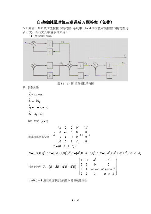
自动控制原理第三章课后习题答案(免费)3-1 判别下列系统的能控性与能观性。
系统中a,b,c,d 的取值对能控性与能观性是否有关,若有关其取值条件如何?(1)系统如图所示。
题3-1(1)图 系统模拟结构图解: 状态变量:11223123434x ax u x bx x x x cx x x dx =+=-=+-=+输出变量: 3y x =由此写出状态空间:0001000011000010(0010)a b x x u c d Y x⎛⎫⎛⎫ ⎪ ⎪- ⎪ ⎪=+ ⎪ ⎪- ⎪ ⎪⎝⎭⎝⎭= 223333[1,0,0,0],[,0,1,0],[,0,,1],[,0,,]T T T B AB a A B a a c A B a a ac c a c d ==-=--=-++---判断能控型:()2323221000001001c a a a U BABA BA B a c a ac c a c d ⎛⎫-- ⎪⎪== ⎪--++ ⎪ ⎪---⎝⎭4c rankU ≠,所以系统不完全能控,讨论系统能控性:判断能观性:022322222001011000C CA c U CA a c b c c CA a ac c b bc c c ⎛⎫⎛⎫ ⎪ ⎪-⎪ ⎪== ⎪ ⎪---- ⎪ ⎪++++-⎝⎭⎝⎭04rankU ≠,所以系统不能观.(2)系统如图所示。
题3-1(2)图 系统模拟结构图解: 状态变量:()1211101[,]1c x a b x ux c d y xa b U B AB c d -⎛⎫⎛⎫⎛⎫=+ ⎪ ⎪ ⎪--⎝⎭⎝⎭⎝⎭=-+⎛⎫== ⎪--⎝⎭若0,a b c d b ----≠则2c rankU =,系统能控.010C U CA a b ⎛⎫⎛⎫== ⎪ ⎪-⎝⎭⎝⎭若0b ≠,则02rankU =,系统能观.(3)系统如下式:1122331122311021010000200000x x x a ux x b x x y c d x y x ∙∙∙⎛⎫-⎛⎫⎛⎫⎛⎫ ⎪ ⎪⎪ ⎪ ⎪=-+⎪⎪ ⎪ ⎪ ⎪⎪ ⎪ ⎪-⎝⎭⎝⎭⎝⎭ ⎪⎝⎭⎛⎫⎛⎫⎛⎫ ⎪= ⎪ ⎪⎪⎝⎭⎝⎭ ⎪⎝⎭解:系统如下:1231122311021010000200000x x x a u x b x y c d x y x -⎛⎫⎛⎫⎛⎫ ⎪⎪ ⎪=-+ ⎪⎪ ⎪ ⎪⎪ ⎪-⎝⎭⎝⎭⎝⎭⎛⎫⎛⎫⎛⎫ ⎪= ⎪ ⎪ ⎪⎝⎭⎝⎭ ⎪⎝⎭若0,0a b ≠≠,系统能控.若0,0c d ≠≠,系统能观.3-2 时不变系统:311113111111x x u y x ∙-⎛⎫⎛⎫=+ ⎪ ⎪-⎝⎭⎝⎭⎛⎫= ⎪-⎝⎭试用两种方法判别其能控性与能观性。
自控控制原理

自控控制原理自控控制原理呀,这就像是我们人生路上的方向盘呢!你想想看,我们的生活就像一辆车,要是没有一个好的自控“方向盘”,那还不得横冲直撞呀!咱就说,每天早上起床,是不是得靠自控才能从那温暖的被窝里挣扎出来呀?要是没有点自控力,那不得一觉睡到中午啊!这就像车要跑偏了,得赶紧把方向盘打回来。
还有啊,面对那些诱人的美食,自控就更重要啦!看见蛋糕、炸鸡就走不动道,那可不行呀!得学会控制自己,不然体重蹭蹭往上涨,那可就麻烦咯。
这就好比开车时要控制速度,不能一脚油门踩到底呀。
再说说学习和工作吧,没有自控力怎么能静下心来好好做事呢?一会儿玩玩手机,一会儿发发呆,那任务啥时候能完成呀?这不就像车在路上走走停停,永远也到不了目的地嘛。
那怎么才能更好地掌握这个自控的“方向盘”呢?首先得有个明确的目标吧,知道自己要往哪儿开。
然后呢,得给自己制定一些规则,就像路上的交通标识一样,不能随便违反。
比如说规定好每天看多久的书,做多久的运动。
就像我自己,以前也是个自控力不太好的人。
我特别喜欢看电视,一看就停不下来。
后来我意识到这样不行啊,得改变。
于是我就规定自己每天只能看一个小时电视,时间一到就坚决关掉。
一开始真的很难做到啊,心里就像有只小猫在挠一样,特别痒痒。
但慢慢地,我就习惯了,自控力也变强了。
还有啊,找个伙伴一起互相监督也很有用哦。
两个人一起努力,比一个人单打独斗可好多啦。
就像车有了副驾驶,能帮着一起看路呢。
咱可别小瞧了这自控控制原理,它真的能让我们的生活变得不一样呢!它能让我们更有条理,更有目标,也更能实现自己的梦想。
所以呀,大家都要好好掌握这个神奇的“方向盘”,让自己的生活这辆车稳稳地向前开,开向我们想去的地方!别再任由自己随意飘荡啦,赶紧握紧这个自控的“方向盘”吧!难道不是吗?原创不易,请尊重原创,谢谢!。
一节控制原理二节控制要求三节控制过程

➢ 控制过多或不足都会影响控制的有效性
建立信息反馈系统
➢ 负有控制责任的管理人员只有及时掌握了反映 实际工作与预期工作绩效之间偏差的信息,才 能迅速采取有效的纠正措施
四川民族学院 曾雪玫
119
纠正偏差
找出偏差产生的主要原因 确定纠偏措施的实施对象:人员、部门、
对象 选择恰当的纠偏措施:
➢预先控制:在企业生产经营活动开始之前进行的 控制,包括检查资源的筹备情况和预测其利用效 果两个方面
➢现场控制:亦称过程控制,是指企业经营过程开 始以后,对活动中的人和事进行指导和监督
➢结果控制:亦称事后控制,是指在一个时期的生 产经营活动已经结束以后,对本期的资源利用状 况及其结果进行总结
2020/12/15
➢没有明确的先行量,控制标准Z是过去时刻已达 状态Kt的函数
Z=f(Kt)
4.最佳控制
➢标准Z值由某一目标函数的最大值或最小值构成, 这种函数通常含有输入量X,传递因子S和K及各 种附加参数C,
➢即:
Z=max f(X、S、K、C)
Z=min f(X、S、K、C)
2020/12/15
四川民族学院 曾雪玫
11
适度控制
控制费用与收益的变化:
成
本
与 收
x2
控制成本
E
控制收益
益
x1
净收益最大
A
BC
控制程度
从理论上来讲,控制程度在与x1和x2相对应的
B、C两点之间为适度控制;低于B点,为控制不足;
高于C点,为控制过剩。
2020/12/15
四川民族学院 曾雪玫
112
客观控制
控制工作应该针对企业的实际状况,采取必 要的纠偏措施,或促进企业活动沿着原先的 轨道继续前进
第一节控制原理第二节控制的要求第三节控制过程-PPT精品

2020/5/28
四川民族学院 曾雪玫
3
控制的基本原理
某洗车制造厂耦合系统示意图
人力 资金
2020/5/28
厂房设备 工艺装备
原材料 能源
协作件
计划文件 技术文件
产品开发 市场研究
铸造 锻造 机加 热处理 冲压 油漆
发动机 底盘 车身
四川民族学院 曾雪玫
汽车 销售
4
控制的类型
根据确定控制标准Z值的方法,控制过程分为 四类
第十七章 控制与控制过程
第一节 控制原理 第二节 控制的要求 第三节 控制过程
2020/5/28
四川民族学院 曾雪玫
1
控制的必要性
无论计划制定得如何周密,由于各种各样的 原因,人们在执行计划的活动中总是会或多 或少地出现与计划不一致的现象 ➢环境的变化 ➢管理权力的分散 ➢工作能力的差异
2020/5/28
11
适度控制
控制费用与收益的变化:
成
本
与 收
x2
控制成本
E
控制收益
益
x1
净收益最大
BC
控制程度
从理论上来讲,控制程度在与x1和x2相对应的
B、C两点之间为适度控制;低于B点,为控制不足;
高于C点,为控制过剩。
2020/5/28
四川民族学院 曾雪玫
112
客观控制
控制工作应该针对企业的实际状况,采取必 要的纠偏措施,或促进企业活动沿着原先的 轨道继续前进
客观的控制源于对企业经营活动状况及其变 化的客观了解和评价
2020/5/28
四川民族学院 曾雪玫
113
弹性控制
有效的控制系统应在遇到突发的、无力抗拒 的变化情况下仍能发挥作用,维持企业的运 营
- 1、下载文档前请自行甄别文档内容的完整性,平台不提供额外的编辑、内容补充、找答案等附加服务。
- 2、"仅部分预览"的文档,不可在线预览部分如存在完整性等问题,可反馈申请退款(可完整预览的文档不适用该条件!)。
- 3、如文档侵犯您的权益,请联系客服反馈,我们会尽快为您处理(人工客服工作时间:9:00-18:30)。
第三章控制系统的时域分析法3-1 系统的瞬态响应及性能指标3-2 劳斯稳定判据3-3 反馈控制系统的稳态误差3-4 增加零极点对二阶系统响应的影响综述系统分析:针对系统的稳定性、稳态误差和瞬态响应三方面的性能指标进行分析。
直接法——在时间域内,直接求解系统的微分方程。
间接法——稳定性判据(Stability Criterion)根轨迹法(Root Locus Method)频率法(Frequency Method)3.1 系统的瞬态响应及性能指标基本概念瞬态响应:系统的输出从输入信号作用时刻起,到稳定状态为止,随时间变化的过程。
分析系统的瞬态响应的方法:1、直接求解法2、间接评价法3、计算机仿真法一、典型输入信号控制系统的瞬态响应与输入信号的形式有关系统分析时通常考虑某些典型输入信号对系统的影响(一)阶跃信号⎩⎨⎧≤>=000t t A t r )(阶跃信号表达式A =1时,称为单位阶跃信号,用1(t )表示(二)斜坡信号⎩⎨⎧≤>=0 00t t At t r )(斜坡信号表达式当A =1时,则称为单位斜坡信号(三)抛物线信号⎪⎩⎪⎨⎧≤>=000 )(t t At t r 221抛物线信号当A =1时,则称为单位抛物线信号(四)脉冲信号⎪⎩⎪⎨⎧><<<=εεεt t t t r 及000 1)(脉冲信号表达式当ε 趋于零时就得理想的单位脉冲信号(亦称d (t )函数)。
(五)正弦信号⎩⎨⎧≤>=000t t t A t r sin )(ω正弦信号表达式A 为幅值T 为周期,角频率ω =2p /T二、性能指标5、延滞时间t d :响应曲线到达终值50%所需的时间主要包括:%)()()(100⨯∞∞-=c c t c p p σ2、最大百分比超调量σp :1、峰值时间t p :响应曲线到达第一个峰值所需的时间3、调整时间t s :响应到达并保持在终值±5%(或±2%)内所需的最短时间4、上升时间t r :响应从终值10%上升到终值90%所需的时间衡量系统性能优劣的标准性能指标图解调整时间t s峰值时间t p上升时间t r超调量延滞时间t d其它性能指标振荡次数N:在0≤t≤t s时间内,过渡过程c(t)穿越其稳态值c(∞)次数的一半。
衰减比n:过渡过程曲线上同方向的相邻两个波峰之比,n =B/B’。
对于定值控制系统:常以系统对单位扰动输入信号时的响应特性来衡量瞬态性能三、瞬态响应1.一阶系统的瞬态响应闭环传递函数11111)()()(+=+++=++==Ts K s kk kks ks R s C s G B ττ输出拉氏变换Ts Ks K s Ts K s C /111)(+-=⋅+=输入r (t )=1(t )或R (s )=1/s 可用一阶微分方程描述其动态过程的系统,称为一阶系统一阶控制系统一阶系统响应曲线一阶系统的单位阶跃响应)1()(/ Tt eK t c --=系统时间常数定义为系统响应达到稳态值的63.2%所需要的时间1+=k T τ响应的稳态值系统输出值与时间常数T 的对应关系:t = T ,c (1T )= 0.632c (∞) t = 2T ,c (2T )= 0.865c (∞) t = 3T ,c (3T )= 0.950c (∞)t = 4T ,c (4T )= 0.982c (∞)一阶系统的稳态误差由于k 不可能为无穷大,所以,系统的稳态误差不能为011)(1)]()([lim )(lim )(+=∞-=-==∞∞→∞→k c t c t r t e e t t 系统的稳态误差2.二阶系统的瞬态响应在分析和设计自动控制系统时,常常把二阶系统的响应特性视为一种基准。
闭环传递函数2222nn nB ss s G ωζωω++=)(ζ为阻尼比,ωn 为无阻尼自然振荡频率典型二阶系统结构以下图R-L-C 电路为例传递函数2222211nn nr c B s s LC s L R s LC RCs LCs s U s U s G ωζωω++=++=++==2/11)()()(无阻尼自然振荡频率2T T LCn 111==ω当R =0时的谐振频率阻尼比1111/T T T L C R L R n n 22222====ωωζ电枢控制的直流电动机输出ω 与电枢电压u a 之间传递函数为22222111/111/1)(nn n c ma a m a c m m a cB s s K T T s T s T T K s T s T T K s G ωζωω++⋅=++⋅=++=2ma n T T 1=ωama n T T T 2211==ωζ典型二阶系统的阶跃响应特性特征方程02=++22nn s s ωζω1121---=-+-=22ζωζωζωζωn n n n s s 解方程阻尼比ζ不同,特征根的性质就不同,系统的响应特性也就不同0<ζ<1,欠阻尼情况ζ =1,临界阻尼情况ζ >1,过阻尼情况①0<ζ<1,欠阻尼情况系统传递函数))(()(2d n d n nB j s j s s G ωζωωζωω-+++=dn j s ωζω±-=2,1有阻尼振荡频率21ζωω-=n d 输入r (t )=1(t )2222222)()(1)()(dn n d n n n n s s s s s s s s C ωζωζωωζωωζωω++-++-=++=2)11sin(111)sin 1(cos 1)]([)(2222ζζζωζωζζωζωζω-+---=-+-==---arctant et t es C t c n td d tn n 1L0<ζ<1,欠阻尼情况(续)(a)根分布(b)单位阶跃响应欠阻尼情况(0<ζ <1)系统的误差为)0()1arctan1sin(11)()()(222≥-+--=-=-t t et c t r t e n tn ζζζωζζω当t →∞时,稳态误差e (∞)=0。
ζ=0,无阻尼情况系统的特征根为一对共轭虚根s 1,2= ±j ωn 单位阶跃响应tt c n ωcos 1)(-=等幅振荡过程,其振荡频率就是无阻尼自然振荡频率ωn 。
当系统有一定阻尼时,ωd 总是小于ωn②ζ =1,临界阻尼情况两个相等的实数特征根:s 1=s 2= -ωnn n n n ns s s s s s C ωωωωω+-+-=+=1)(1)()(222)1(1)(t e t c n tnωω+-=-(a)根分布(b)单位阶跃响应临界阻尼情况(ζ =1)系统输出的拉氏变换无超调,无振荡,单调响应过程③ζ >1,过阻尼情况两个不相等的实数根:nsωζζ)1(22,1-±-=nnssssCωζζζζζωζζζζζ)1()]1(1[)1()]1(1[1)(21222122-++-+-+--+----=--22)11(111)(2)1(2)1(222-+-----=-+----ζζζζζωζζωζζtt nn eet c2(a)根分布(b)单位阶跃响应无超调,过程拖得比ζ=1时长不同ζ值下的二阶系统单位阶跃响应曲线族在一定ζ 值下,欠阻尼系统比临界阻尼系统更快地达到稳态值,过阻尼系统反应迟钝,动作很缓慢,所以一般系统大多设计成欠阻尼系统二阶系统的脉冲响应特性输入单位脉冲信号d (t ),即R (s )=1二阶系统单位脉冲响应的拉氏变换为2222)()()(nn nB s s s R s G sC ωζωω++==系统的单位脉冲响应]2[)]([)(22211nn nB s s L s G t c ωζωω++==--L 欠阻尼情况(0<ζ <1)te t c n t nn 221sin 1)(ζωζωζω--=-临界阻尼情况(ζ =1)tn n tet c ωω-=2)(过阻尼情况(ζ >1)][1)()1()1(222ttnn n eet c ωζζωζζζω-+------=2不同 值时的单位脉冲响应曲线四、二阶系统的瞬态响应性能指标工程实际中往往习惯把二阶系统调整为欠阻尼过程,主要的性能指标:上升时间、峰值时间、最大超调量、调节时间上升时间t r (rise time))11sin(111)(222ζζζωζζω-+---=-arctant et c n tn ⎪⎪⎩⎪⎪⎨⎧--==-+ζζωωζζω221sin 1cos r d r d r d t t t tan 0dd r t ωφp ζζω-=--=)1arctan(12ζζφ21arctan-=c (t r )为1峰值时间t p (peak time))11sin(111)(222ζζζωζζω-+---=-arctant et c n tn ),3,2,1( ==m m t d pω求导0)sin(1)cos(11)(22=+-++--=--ϕωζωζωϕωζζωζωt e t e dt t dc d n td d t n n ⎪⎩⎪⎨⎧=-==+=+-+ϕζζζωωϕωϕωζωϕωωtan 1)tan()sin()cos(2n dd d n d d t t t 0整理到达第一个峰值时m =121ζωpωp -==n dp t 峰值时间:峰值时间t p 与振荡频率ωd 成反比。
当ωn 一定,ζ 越小,t p 也越小最大超调量σp(percent overshot)代入t=tp)11sin(111)(222ζζζωζζω-+---=-arctant et c n tn ∵Aeeeet et c d d p n t p n npn =+=-+=+--=+--=-+---=---------222212121212221sin 11)sin(11)sin(11)11sin(111)(ζζpζζpζζpζωpζωζωϕζϕp ζϕωp ωζζζζωζarctan最大超调量σp 求法(续)%)()()(%100⨯∞∞-=c c t c p p σσp 与ζ 的关系%%21100⨯=--ζζpσep ∴%10011121⨯-+=--ζζpe调节时间t s)1%ln(12ζd ζω--=ns t ⎪⎪⎩⎪⎪⎨⎧±==±==)4)32%%(5%%(d ζωd ζωn s n s t t )(%)()(∞≤∞-c c t c d 由t s 定义21%ζd ζω-≤∴-tne%1,1)sin(%)sin(122d ζϕωd ϕωζζωζω≤-∴≤+≤+---td d tn n et t e近似算法%1)sin(112d ϕωζζω≤-+---t ed tn 两边取对数小结当ωn 一定,要减小t r 和t p ,必须减少ζ 值,要减少t s 则应增大ζωn 值,而且ζ 值有一定范围,不能过大增大ωn ,能使t r ,t p 和t s 都减少最大超调量σp 只由ζ 决定,ζ 越小,σp 越大。
