TDA8172中文资料
电子器件代换及电器维修心得汇总

1.STV8172A(+-14v供电)能用TDA8172A、TDA8172或LA78045代换,当用TDA8177代换时下部线性不良。
2.康佳T21SA073超级芯片:LA769317L55N7-E(CKP1504S)能用LA76931H7L57L2E(CKP1504S5)代换3.康佳T21SA073电源部份三极管MPSA06(NPN:80V 0.5A 0.625W)用C2383代换A327A用A966代换待机45V 工作108V。
如用A1015和C1815则电源噪声较小!原机P21SA376为36V。
4.康佳T21SK026超级芯片:OM8370PS/N3/2/1587能用T25SK076的OM8373PS/N3/A/1586代换5.西湖P21Z57彩电TV时无伴音:OM8371PS/N3/1(NOM8371-A-24CG)的31脚330P漏电5~6K,此机2A V+1SVSH,A V时OM8371-7脚是音量控制(PWM)去控制功放AN7823A-9脚(0~1.2V)而TV时控制的是OM8371-44脚信号幅度,OM8371-7输出的是DC电压且VOL最小时为0V,最大时为3.5V。
加华14''也是OM8371PS/N3/1(NOM8371-A-24CG),进总线方法相同多是菜单键后6483,键盘1234选项.但它是1路A V,软件能互完,就是A V数目不对,总线菜单中末见A V修正选项.它是OM8371-8脚为静音控制,A V音频送OM8371-35脚,超级IC内部控制44脚信号幅度.5.1.华夏之星夏华Y3430 (1P30机芯)NOM8373-B-6ND(050322)进总线法:能用茄华RC01-31,安MENU后输入6483进入IIC屏显M,键盘1234选项,安待机键退出记忆.此机在网上找到的进总线方法多是LA76828机芯,说明此机有2个版本!7.创维25TM9000机电源管BUT12AX(1000V/8A/23W)能用BUT11AX(1000V/5A/32W)代用(当用BU2527AX加引线接入后+B只有20V8.TCL-AT21xx: 场块STV9302A(+-14V供电)能用STV9302B代换9.创维29T83HT CPU供电管A1930能用B940A代换,C极串联电阻为100欧2W,宜用水泥3W,其阻值与+B待机电压成正比,选取100欧姆时+B在60V左右.配机管A1930/CD2051:180V 1.5A 10W29T91AA机的待机管CD2051能用A940代换,此机串联电阻为10欧姆/1W B+:34V/140V 10.三洋CK25F90特殊散焦:故障现象调聚焦电压时(G2电压也变)图象亮暗变化如同调G2电压,更换高压包和管座无效,但低亮度时聚焦好转,后来调足聚焦电压再调G2电压使亮度适当,连续开机2~3小时后聚焦恢复正常,第二天冷开机也正常,但调聚焦电压时仍然亮暗变化好在始终不散焦.G2在415V左右,KR.G.B在160V左右,图象质量还可以,此机是三洋25’’纯平管.用了3天后用户反应彩色时好时坏。
元器件的替换资料

元器件的替换资料1.健伍激光头KCP1H的代换经过在长虹VD9000型VCD机上试⽤,索尼KSS-213激光头直接代换健伍KCP1H激光头,代换后装⼊碟⽚试机⼀切正常,以前不能读的碟⽚都能很快读出,⽽且播放效果良好。
2.长虹R2118AE彩电中周ST6019的代⽤中周ST6019可⽤TC31157和TRF1162T代换。
3.29英⼨⾼清⾏输出管在代⽤时的注意事项因为100Hz彩电⾏频是普通机型的2倍,对⾏输出管的⼯作频率要求⾼,除了要满⾜普通彩电的条件外,还须考虑其下降时间是普通彩电⾏输出管的tf=lIxs左右,⽽100Hz彩电的⾏榆出管则要求其tf⼩于O.6µs。
4.应⽤于电磁炉(灶)绝缘栅双极晶体管(IGBT)的参数要求应⽤于电磁炉(灶)的IGBT管应选取BVceo≥1000V、ICm≥7A、PCM≥100W、β≥40的。
才能保证其在电路上胜任。
5.三洋系列机芯彩电4.43M晶振的代换三洋系列机芯彩电中的UPC1423、LA7685、LA7688、LA76810集成电路,晶振均为4.43MHz,损坏后出现的故障多种多样,市⾯上所售⼀般的4.43M晶振均⽆法直接更换,经摸索发现,只要在晶振引脚上串接⼀个10-18P的电容,⼏乎都能代换成功。
6.康佳F953DB彩电中周的代换康佳F953DB彩电中周型号为2703119,可以⽤1445、7851、丽恒703025类似功能的中周代⽤。
7.嘉华25S5彩电CPU的代换DMC73C167-004(英⽂菜单)代换DMC73C16-003(中⽂菜单)⽅法,将DMC73C167-004第28,29脚去掉,按脚位顺序装上即可。
8.关于IIC总线彩电微处理器的代换原则由于IIC总线彩电微处理器是⼀个数字电路系统,它的⼯作状态或功能是由存储的数据所决定的。
所以它的代⽤就不同于模拟电路的集成电路,只是脚功能相同、⼯作环境和条件相同就可以代换。
原则上以原型号(连后缀也要相同)代换,也可以⽤引脚功能相同的其他型号代换,但需要同时更换配套的存储器数据。
仪表放大器应用
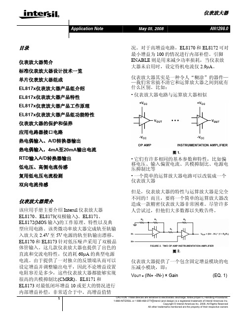
此处,A代表输出级增益。 假设 Ry/Re = 1 (即Re和Ry阻值相同)。那么:
图 10. 两个放大器组成的仪表放大电路
由于A值非常高,所以得到:
EL817x仪表放大器产品组功能特性
EL8171、EL8173 简化电路示意图如图 11 所 示,它描绘了输入、输出的轨至轨工作过程。 该电路图同样应用于 EL8170、EL8172,只需 将 PNP 晶体管(Q1-Q4)替换成针对超低输入偏 置电流的 P-沟道 MOSFET。
电压 (IN+和 IN-)的情况下使用。但是输入阻 抗是由 R3 和 R4 的电阻值决定,并不提供高输 入抵抗。这在仪表放大电路中是很常见的。
此外,由于共模抑制比(CMRR)会随着任何有 助于 R4 阻值增加并使 R2 和 R4 失配的源阻抗 而衰减,REF 输入必须由一个非常低的源阻抗 来驱动。
图 4.
(EQ. 5)
VOUT = (IN+ - IN-) × Gain + VREF
(EQ. 2)
x = R4 /(R3 +R4) ×(R1 +R2) /R1 - R2/R1 (EQ. 6)
更糟的情况是,共模抑制比发生在 R4 和 R1 容 差处于最高值、R2 和 R3 处于最低值的时候。 表 1 显示的是增益为 1、10、100 的情况下, 电阻容差与共模抑制比的关系。
电阻 容差
±5% ±1% ±0.1% ±0.01%
表 1.
增益为1 -20.4dB -34.1dB -54.0dB -74.0dB
共模抑制比 增益为10 -15.6dB -28.9dB -48.8dB -68.8dB
厦华P24机芯介绍

厦华P24机芯介绍厦华P24机芯是采用菲利莆片的一款性能的价格比较高的机芯,该机芯调试简单,工艺性好,现就其电源、解码芯片、枕校电路做个技术性介绍(以厦华XT-2560/2980)机划为例)一、开关电源本机芯采用自激式脉冲调宽开关电源,具体电路见图<l>。
1.低通滤波电路AC220V经电源线勾焊在A1、A2焊片上,经保险丝FU501,进入由C509、R503、L501、C508组成的低通滤波器,通过插头X503到电源开关,然后回到插头X502分三路输出:一路送到由RT501、X501组成的消磁电路;另一路送到桥式整流电路,第三路径T501降压、整流、稳压后,产生+5V的待机电压,送CPU及遥控电路。
该低通滤波器用于防止高频干扰信号通过电源线进入电视机而产生的干扰,同时防止机内的高频脉冲进入交流电网造成污染。
2.待机电压产生电路该电路由降压变压器T501、桥式整流二极管VD505~VD 508,高频滤波电容c510~C513。
滤波电容C514,降压电阻RT504以及由R505、C 515、VD 509、V501、C 517、C 516 组成的稳压电路组成。
用于为N801提供+5V工作电压,红外接收头工作电压,电源指示灯电压。
3.自动消磁电路自动消磁电路由正温度系数热敏电阻RT501,消磁线圈X501组成,刚接通电源时RT501电阻值很小,X501中有很大电流流过,该电流在通过RT501时,使其温度上升,电阻值迅速增加,流过X501的电流急剧衰减,在消磁线圈X501周围产生一个由强到弱变化的交变磁场,以消除由显象管荫罩板上的杂散磁场造成的光栅色纯不良。
4.整流和滤波电路整流由VD501-VD504组成的桥式整流电路,高频滤波电容C501-C504,限流电阻R501组成。
滤波由C505、C506组成。
用于将AC20V电压转DC300V电压。
5.开关稳压电路(1)电源的启动和开关电源的自激振荡过程整流和滤波电路输出的+300V电压,一路经开关变压器T502的初级绕组6 ~ 9加到开关调整管V504 C极,另一路经由R509、R511、R517组成的启动电路,为V504提供1b,使V504导通,产生IC,流过T502的初级绕组,产生6正9负的自感电。
TDA8172

地
热保护
5
输 出
-1-
TDA8172
极限参数
符号
参数名称
数 值 单位
Vs
电源电压(2 脚对 4 脚)
V6
回扫脉冲电压(6 脚对 4 脚)
V1,V7
功放输入电压(PIN1/7 对 4 脚)
Io
最大输出电流,t=2mS,不可重复
Io
最大输出电流 f = 50 或 60 Hzs, t ≤ 10μS
Io
最大输出电流 f = 50 或 60 Hzs, t > 10μS
I3
3 脚直流电流(当 V5<V2 时)
I3
3 脚回扫电流(f = 50 或 60 Hzs,tfly<1.5mS)
Topr
工作温度
Tstg 、Tj 贮存温度和结温
Rth(j-c)
热阻
电参数(除非特别说明,Vs=35V,Ta=25℃)
符号 参数名称
场位置调整
Vref-
+Vs CF
26
3
1 功率 放大
7
TDA8172/LS 4
-VEE
回扫脉冲产生
热保护
5
0.47 300 YOKE
0.22uF
R2
R1
附:直流测试线路
+Vs
I2
I6
2
6
TD A 8172/LS
7
4
5
10k
S1
a
1
b
V7
I1
1V
S 1 : a = I2 & I6 ; b = I1 测试图:1a
测试条件
Min.
I2
2 脚静态工作电流
LMV8172中文资料
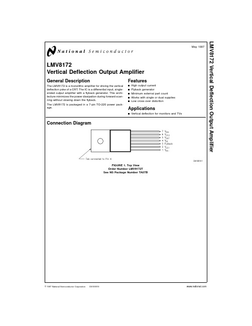
LMV8172Vertical Deflection Output AmplifierGeneral DescriptionThe LMV8172is a monolithic amplifier for driving the vertical deflection yoke of a CRT.The IC is a differential input,single-ended output amplifier with a flyback generator.This archi-tecture minimizes the power dissipation during forward scan-ning without slowing down the flyback.The LMV8172is packaged in a 7-pin TO-220power pack-age.Featuresn High output current n Flyback generatorn Minimum external part countn Works with single or dual supplies nLow cross-over distortionApplicationsn Vertical deflection for monitors and TVsConnection DiagramDS100010-1FIGURE 1.Top View Order Number LMV8172T See NS Package Number TA07BMay 1997LMV8172Vertical Deflection Output Amplifier©1997National Semiconductor Corporation Absolute Maximum Ratings(Notes1, 3)If Military/Aerospace specified devices are required, please contact the National Semiconductor Sales Office/ Distributors for availability and specifications.Supply Voltage,(V S=V CC1−V EE)35V Flyback Peak Voltage,(V OUT−V EE)60V (V CC2−V EE)60V Input Voltage,(V DC)Pins1,7V EE≤V IN≤V CC1 Output Peak Current,(I O)Pin5(Note8) 3.2A pp Power Dissipation(P D)T C=25˚C41WT C=90˚C20W Above25˚C,derate based onθJC and T J(Note4) Thermal Resistance(θJC)3˚C/W Junction Temperature(T JMAX)150˚C ESD Susceptibility(Note5)2kV Storage Temperature−65˚C to+80˚C Lead Temperature(Soldering10seconds)265˚C Operating Ratings(Note2)Junction Temperature Range−20˚C≤T J≤+150˚CElectrical CharacteristicsV CC1=+17.5V;V CC2=+16.9V;V EE=−17.5V;T C=25˚C unless otherwise specified.Symbol Parameter Conditions Typical(Note6)Limit(Note7)UnitsI2+6Total Quiescent Current(I2+I6)See Figure21120mA(max) I1Input Bias Current-0.5-2.0µA(max) I os Input Offset Current0.5 3.0µA(max) V3L Pin3Saturation Voltage to V EE See Figure3,I3=20mA 1.1 2.0V(max) V5L Output Saturation Voltage to V EE See Figure3,I5=1.2A 1.3 2.5V(max)I5=0.7A0.7 1.4V(max)V5H Output Saturation Voltage toV CC2See Figure4,I5=−1.2A 2.6 3.3V(max) I5=−0.7A 2.1 2.8V(max)Note1:Absolute Maximum Ratings indicate limits beyond which damage to the device may occur.Note2:Operating Ratings indicate conditions for which the device is functional,but do not guarantee specific performance limits.For guaranteed specifications and test conditions,see the Electrical Characteristics.The guaranteed specifications apply only for the test conditions listed.Some performance characteristics may de-grade when the device is not operated under the listed test conditions.Note3:All voltages are measured with respect to GND,unless otherwise specified.Note4:The maximum power dissipation must be derated at elevated temperatures and is dictated by T JMAX,θJC and the case temperature,T C.The maximum al-lowable power dissipation at any elevated temperature is P D=(T JMAX−T C)/θJC or the number given in the Absolute Maximum Ratings,whichever is lower.For this device,T JMAX=150˚C.The typical thermal resistance(θJC)of the LMV8172is3˚C/W.Note5:Human Body model,100pF capacitor discharged through a1.5kΩresistor.Note6:Typicals are at T C=25˚C and represent most likely parametric norm.Note7:Tested limits are guaranteed to National’s AOQL(Average Outgoing Quality Level).Note8:Maximum output current is tested with a load of3mH,V CC1=+15V and V EE=−15V,V IN+set so the device is drawing equal amounts of current from both supplies,and the sawtooth on V IN−set so the voltage waveform on pin5is as large as possible without distortion.2Test CircuitsDS100010-2FIGURE2.DS100010-3FIGURE3.Test Circuits(Continued)Block DiagramApplication HintsTo get the best possible performance from the LMV8172T it is important to use a good PCB layout and the correct com-ponents.The 0.1µF and 470µF capacitors on the V CC1and V EE lines should be as close as possible to their pins.The power traces should be wide and there should be no jumpers between the capacitors and the LMV8172T.The value of theelectrolytic capacitors used on the V CC1and V EE lines should be 470µF or greater.The ground traces should also be as wide as possible.The diode and optional capacitor should be located close to the LMV8172T.The diode should be a fast-recovery type,the 1N4937recommended has a t rr of 150ns.The capacitor is optional,it may be needed in some PCB layouts.A suggested layout is shown in Figure 6.DS100010-4FIGURE 4.DS100010-5FIGURE 5. 4Application Hints(Continued)Typical ApplicationDS100010-6FIGURE 6.DS100010-7FIGURE 7.Physical Dimensions inches(millimeters)unless otherwise notedLIFE SUPPORT POLICYNATIONAL’S PRODUCTS ARE NOT AUTHORIZED FOR USE AS CRITICAL COMPONENTS IN LIFE SUPPORT DE-VICES OR SYSTEMS WITHOUT THE EXPRESS WRITTEN APPROVAL OF THE PRESIDENT OF NATIONAL SEMI-CONDUCTOR CORPORATION.As used herein:1.Life support devices or systems are devices or sys-tems which,(a)are intended for surgical implant intothe body,or(b)support or sustain life,and whose fail-ure to perform when properly used in accordancewith instructions for use provided in the labeling,canbe reasonably expected to result in a significant injuryto the user.2.A critical component in any component of a life supportdevice or system whose failure to perform can be rea-sonably expected to cause the failure of the life supportdevice or system,or to affect its safety or effectiveness.National SemiconductorCorporationAmericasTel:1-800-272-9959Fax:1-800-737-7018Email:support@National SemiconductorEuropeFax:+49(0)180-5308586Email:europe.support@Deutsch Tel:+49(0)180-5308585English Tel:+49(0)180-5327832Français Tel:+49(0)180-5329358Italiano Tel:+49(0)180-5341680National SemiconductorHong Kong Ltd.13th Floor,Straight Block,Ocean Centre,5Canton Rd.Tsimshatsui,KowloonHong KongTel:(852)2737-1600Fax:(852)2736-9960National SemiconductorJapan Ltd.Tel:81-3-5620-6175Fax:81-3-5620-6179Order Number LMV8172TNS Package Number TA07BLMV8172VerticalDeflectionOutputAmplifierNational does not assume any responsibility for use of any circuitry described,no circuit patent licenses are implied and National reserves the right at any time without notice to change said circuitry and specifications.。
BC817中文资料_数据手册_参数

MARKING CODE(1)
6D∗ 6A∗
TYPE NUMBER
BC817-25 BC817-40
Note
1. ∗ = p : Made in Hong Kong. ∗ = t : Made in Malaysia.
MARKING CODE(1)
6B∗ 6C∗
handbook, halfpage
3
1999 Jun 01
5
Philips Semiconductors
NPN general purpose transistor
PACKAGE OUTLINE Plastic surface mounted package; 3 leads
Product specification
BC817
SOT23
IC = 500 mA; VCE = 1 V; note 2
collector capacitance
IE = ie = 0; VCB = 10 V; f = 1 MHz;
transition frequency
IC = 10 mA; VCE = 5 V; f = 100 MHz;
Notes 1. Pulse test: tp ≤ 300 µs; δ ≤ 0.02. 2. VBE decreases by approx. 2 mV/K with increasing temperature.
Austria: Computerstr. 6, A-1101 WIEN, P.O. Box 213, Tel. +43 1 60 101 1248, Fax. +43 1 60 101 1210
D
B
E
A
X
3
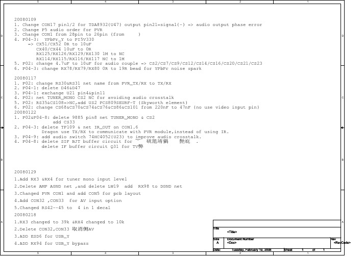
英华家电维修软件提供资料-8R08机芯图纸
AV_YPBPR_SEL DGND
SPI_CS# SPI_SCK SPI_DI SPI_DO
I2C
I2C_M1_SDA I2C_M1_SCL I2C_M1_SDA I2C_M1_SCL
RS1 Tuner_CVBS+
51 CS3
LS1
1uH CS4
CS1
47nF VIN0P
Delete 9885 pin8 net TUNER_MONO & CS2 Add CS33 Pin215/216 Default:H Delete net USB_L/R & CS7/CS9 Add CS34&CS37 Add net USB-VGA_L/R
A
5.Changed RS42--45 to
1.RX3 changed to 39k &RX4 changed to 10k 2.Delete CON32,CON33 取消侧AV 3.ADD ESD6 for USB_Y 4.ADD RX94 for USB_Y bypass
5 4 3
Title <Title> Size A Date: Document Number <Doc> Tuesday, February 19, 2008
REALTEK ELECTRONIC CO., LTD. BLOCK DIGRAM
Document Number
A
Dragon LCD TV Controller
Sheet 1
1
Rev D 16
Tuesday, February 19, 2008
2
of
5
4
3
2
1
DGND
SPI FLASH
彩色显示器行场扫描电路检测

广州白云技师学院电子信息系硬件维修系列教程彩色显示器行场扫描电路检测一、目的要求1、了解行场扫描电路的组成及工作原理;2、了解二次电源的组成及工作原理3、熟悉行场扫描电路的检测方法。
4、了解行场枕形校正电路工作原理以及控制过程。
二、知识要点TDA9109为采用I²C总线控制的自动同步多频彩显偏转信号处理器,可以自动适应不同的扫描频率,其最高工作行频为150KHz,场频工作范围为50—165Hz。
CPU电路通过I²C总线可对TDA9109的行场中心、场幅、场S及C失真校正以及枕校等进行控制。
三、设备材料彩色显示器NPT1556S型、电脑主机、电源线、双踪或ST16示波器、万用表、电缆及分配器。
四、技能训练及要点1、在彩显中找出行场扫描电路的主要元器件⑴I²C总线控制行场振荡及行场几何校正IC601SID2511C01-A0(注:与TDA9109完全一样);⑵场推动及场输出IC301TDA8172、场偏转线圈与泵电容C304;⑶行推动级Q624、行推动变压器T610;⑷行输出级Q601、行输出变压器(FBT)、双阻尼二极管D601(注意观察其外型)⑸行枕校电路:A、行幅调节电路:Q620、Q610、S校正电容C626B、自动S校正电路:静噪控制管Q603、CS控制及切换管Q651、Q650C、行频锁定检测管Q602说明:行频未锁定时,IC6013脚输出低电平,则Q602截止,视频静噪电路起控,MUTE端为高电平,则CS不可调,栅极G1不可调。
(6)二次电源:+B驱动放大管Q631、Q632,开关管Q630,储能电感L603,二次整流二极管D632,二次滤波电容C635说明:不同扫描模式的行扫描频率相差很大(15寸以下彩显的行频率范围为30~54KHZ,大屏幕彩显的行频率范围更大)。
为了保证不同的扫描模式下有正常的行扫描幅度及适当的高压,彩显在不同模式下的行电源电压也因行扫描频率不同而异,行频较高时行电源电压也较高。
001高频头宽频接收机技术说明书
淘宝网址:/shop/view_shop.htm?mytmenu=mdianpu&utkn=g,w243noodvo3ps132273730706 2&user_number_id=133702025QQ:11735804001高频头宽频立体声收音机接收机一机器简介市场上出售的FM收音机一般采用简单的一次变频技术,只能接收88~108MHz调频广播,而且频带窄、灵敏度低。
普通的电视伴音收音机一般灵敏度都非常低、接收频道少,难以满足人们“听电视”的需求。
001接收机采用先进的二次变频接收技术。
其基本原理是将高性能彩电高频头的伴音信号进行解调,还原出45M-870M的声音信号。
主要芯片:日本索尼公司声场的CAX1238M,它含有高放、混频、中放、限幅、鉴频和立体声解码等全部功能。
功放采用菲利普TDA7050T双声道功率放大器,声音清晰。
30V调谐电源采用DC-DC逆变专用MC34063产生,电压稳定。
淘宝网址:/shop/view_shop.htm?mytmenu=mdianpu&utkn=g,w243noodvo3ps132273730706 2&user_number_id=133702025QQ:11735804二功用特点(一)应用范围广该立体声接收机可以接收45~870MHz频率内的广播、飞机、船舶、车台、对讲机、业余和蜂窝移动通讯信号,还可以接收全频道电视伴音。
可以接在有线电视接收全部的有线电视伴音,还可以与监视器配套成为一台全频道电视接收机,也可以作为修理电视机时的信号源。
还有很多未发掘的潜能…(二)调谐方便快捷独创的飞轮调谐技术,结合多圈精密电位器可以快速的调谐到你想要的频率,并可以精细的调准频率。
调谐速度不输于数调机,定位速度快、精准。
有数调机不可比拟的手感优势。
(三)灵敏度高由于采用高性能高频头+二次变频接收板使该机灵敏度远远高于普通接收设备。
在接收对讲机信号方面不输于普通对讲机。
更多难得资料请到江南家电维修论坛下载!
一:机芯介绍机芯功能介绍在功能上可以实现模拟PAL制式电视信号的60HZ逐行、100HZ两种扫描模式,高清信号可以显示1080P/60,1080I/60,1080I/50,720P/60和逐行DVD 信号(图像)。
VGA方式支持640*480/60 800*600/60 1024*768/60三种模式。
产品外观介绍HDP2433为33系列外观二、机芯概述HDP2433机芯是采用华亚公司的芯片HTV180单芯片的视频处理方案,HTV180集成了ADC ,解码器,OSD 产生器,行场频转换处理芯片以及CPU 。
采用了东芝的TB1306,其功能是预视放、行场激励输出、EW 输出、EHT 、ABL 。
解码板板号是RSAG7.820.947A 。
主板是RSAG7.820.983,主板伴音切换芯片采用HEF4052BP ,伴音功放电路为ST 的TFA9842AJ ,其功能是3路声音输入,总线用两个I/O 口控制切换实现一路输出到伴音功放芯片TFA9842AJ ,总线用一路PWM 控制TFA9842AJ 的VOLUME 脚(7脚)实现音量控制。
视放板板号RSAG7.820.954,采用美国国家半导体的LM2451视放电路。
更多难得资料请到江南家电维修论坛下载!三、原理说明电源部分1:电源框图电源部分工作原理介绍本电源控制芯片采用FAIRCHILD公司的开关电源集成电路FSCQ1265,这是一种内置功率MOSFET和控制器的回扫型开关电源集成电路,且具有过流、过压、过热保护电路。
交流220V经过整流、稳压后提供给开关变压器T501,开关变压器共有5路输出:+B(130V)、+15V、+17V和+8V,10V。
+17V输出开关变压器16脚输出经整流后给N601(TFA9842AJ)第9脚提供电压+10V输出:通过变压器14脚整流输出10V给7805给解码板CPU供电5V-1,给光藕提供参考电压。
+8V输出:通过变压器18脚整流输出8V给3852调制5V 给解码板供电5V-2。
EL817C中文资料

EL817C中⽂资料PhotocouplerEL817L Series Features:Current transfer ratio(CTR:MIN.50% at IF =5mA ,VCE =5V)High isolation voltage between inputand output (Viso=5000 V rms )Compact dual-in-line packageEL817L*:1-channel typePb freeUL approved (No. E214129)VDE approved (No. 132249)SEMKO approved (No. 0143133/01-03)NEMKO approved (No. P0*******)DEMKO approved (No. 310352-04)FIMKO approved (No. FI 16763A2)CSA approved (No. 1143601)BSI approved (No. 8592 / 8593)Options available:-Leads with 0.4”(10.16mm) spacing (M Type)-Leads bends for surface mounting (S Type)-Tape and Reel of TypeⅠ for SMD(Add”-TA” Suffix)-Tape and Reel of TypeⅡ for SMD(Add”-TB” Suffix)-The tape is 16mm and is wound on a 33cm reelThe product itself will remain within RoHS compliant version. DescriptionThe EL817 series contains a infrared emitting diode opticallycoupled to a phototransistor. It is packaged in a 4-pin DIP package and available in wide-lead spacing and SMD option. ApplicationsComputer terminalsSystem appliances, measuring instrumentsRegisters, copiers, automatic vending machinesCassette type recorderElectric home appliances, such as fan heaters, etc.Signal transmission between circuits of different potentials PhotocouplerEL817L Series and impedancesPhotocouplerEL817L Series2. Factory code shall be marked (T: Taiwan / C: China)3. Year date code4. 2-digit work week5. All dimensions are in millimeters6. Specifications are subject to change without notice PhotocouplerEL817L SeriesAbsolute Maximum Ratings ( Ta=25°C )UnitRatingParameter SymbolmACurrent I F 80ForwardInput Reverse Voltage V R 6mWPower Dissipation P 150mWCollector Power Dissipation P C 150mACurrent I C 50Output CollectorVoltageV CEO 35 VCollector-EmitterV ECO 6 VEmitter-CollectorVoltageTotal Power Dissipation Ptot 200 mW*1 Isolation Voltage Viso 5000rmsV-55~+110°C Operating Temperature ToprStorage Temperature Tstg -55~+125 °C*2 Soldering Temperature Tsol 260°C*1 AC for 1 minute, R.H= 40~ 60%RH-Isolation voltage shall be measured using the following method.) (1) Short between anode and cathode on the primary side and) between collector, emitter and base on the secondary side.) (2) The isolation voltage tester with zero-cross circuit shall be used. ) (3) The waveform of applied voltage shall be a sine wave*2 For 10 secondsPhotocouplerEL817L SeriesElectro-Optical Characteristics (Ta=25°C)Parameter SymbolTyp.Max.Unit ConditionForward VF- 1.2 1.4 V I F=20mAReverse Current I R - - 10 uA V R=4VInputTerminal Ct - 30 250 pF V=0,f=1kHz CollectorDark currentI CEO - - 100 nA V CE=20VOutput Collector-EmitterbreakdownvoltageBV CEO 80 - - V Ic=0.1mA CurrentTransfer ratio CTR 50-600 % IF=5mA ,V CE=5VCollector-Emitter saturation voltage V CE(sat) - 0.1 0.2 V I F=20mA ,Ic=1 mAIsolationresistanceR ISO5×10101011 - ?DC500V,40~60%R.H Floation capacitance Cf - 0.6 1.0 pF V=0,f=1MHzCut-off frequency fc - 80 - kHzV CE=5V, I C=2 mAR L=100?, -3dBTransfer CharacteristicsRise time t r - 4 18 us V CE=2VI C=2mA,R L=100? PhotocouplerEL817L Series Fall time t f - 3 18 us SupplementPhotocouplerPhotocouplerEL817L SeriesRELIABILITY PLANz The reliability of products shall be satisfied with items listed below. Confidence level : 90 % , LTPD : 10 %PhotocouplerEL817L Series Classification Test Item Description & Condition (Acc.) SampleFailureCriteriaReferenceStandard Operation Life * Ta = 25±3°CIR: If = 50 mAPt: Pc = 130 mW ( Vf=1.4v) , 1000hrs0 / 22 MIL-S-750 : 1026MIL-S-883 : 1005JIS C 7021 : B-1High Temperature / HighHumidity Reverse Bias(H3TRB)Ta = 85 ±3°C , Humi. = 85 % rhPt: 80% * Vce (max rating) , 1000hrs0 / 22 JIS C 7021 : B-11High TemperatureReverse Bias (HTRB)Ta = 105 ±3°CPt: 100% * Vce (Max rating) ,1000 hrs0 / 22 JIS C 7021 : B-8Low Temperature Storage Ta = -50 ±3°C , 1000 hrs 0 / 22 JIS C 7021 : B-12 High TemperatureStorageTa = 125 ±3°C , 1000 hrs 0 / 22 JIS C 7021 : B-10MIL-S-883 : 1008 EndurancetestAuto clave P = 15 PSIG , Ta = 121 °C ,Humi. = 100 % rh , 48 hrs0 / 22 JESD 22-A102-BTemperature Cycling(Air to Air)125°C ~ - 55 °C30 ~ 30 min , 100 cycles0 / 22 MIL-S-883 :1010JIS C 7021 : A-4 Thermal Shock(Liquid to Liquid)125 ~ - 55°Ct (dwell) = 5 mint (trans.) = 10 sec , 100 cycles0 / 22 MIL-S-202 : 107DMIL-S-750 : 1051MIL-S-883 :1011 Solder Resistance Ta = 260 ±3°C t (dwell) = 10 ±1 sec0 / 22 MIL-S-750 : 2031JIS C 7021 : A-1 EnvironmentalTestSolder Ability Ta = 230 ±3 °Ct (dwell) = 5 ±1 sec0 / 22CTR shift > 1.2Vf > U* 1.0Ir > U * 1.0Vce(sat) >U*1.0Bvceo < L*1.0Bveco < L*1.0L :LowSpec.LimitU : Up Spec.LimitMIL-S-883 : 2003JIS C 7021 : A-2z Packing Quantity1. 100 Pcs/ Per Tube2. 25 Tubes / Inner Carton3.12 Inner Cartons / Outside CartonPhotocouplerEL817L Seriesz Packing Quantity1. 1,000 Pcs / Per Reel2. 3 Reels / Inner Carton3. 10 Inner Cartons / Outside Carton。
TDA8175中文资料

TDA8175TV VERTICAL DEFLECTION OUTPUT CIRCUITSeptember 199********Tab connecte dto Pin 4OUTPUT STAGE SUPPLY OUTPUT GROUNDFLYBACK GENERATOR SUPPLY VOLTAGE INVERTING INPUTINPUT8175-01.E P SPIN CONNECTIONSHEPTAWATT (Plastic Package)ORDER CODE :TDA8175.POWER AMPLIFIER .FLYBACK GENERATOR.AUTOMATIC PUMPING COMPENSATION .THERMAL PROTECTION .REFERENCE VOLTAGEDESCRIPTIONThe TDA8175is a monolithic integrated circuit in HEPTAWATT package.It is a high efficiency power booster for direct driving of vertical windings of TV yokes.It is intended for use in Color and B &W television sets as well as in monitors and displays.Flyback GeneratorThermal Protection3621754YOKE+V SVari a bl e Gain Amplifi e rVari a bl e Gain Amplifi e rPower Amplifier1N400135V 220µF 0.1µF 1000µF 35V1.5Ω0.1µF200Ω22k Ω15k Ω1000µF 16V 2Ω8.2k Ω8175-02.E P SBLOCK DIAGRAM1/3THERMAL PROTECTIONThe thermal protection circuit intervenes when the die temperatures reaches 150o C and turns-off the output power device.PUMPING COMPENSATIONThe device incorporatesa special preampliflier,the gain of which varies withchanges in supplyvoltage.This functionallows perfect compensationof height variations caused by changes in brightness.ABSOLUTE MAXIMUM RATINGSSymbol ParameterValue Unit V S Supply Voltage (PIn 2)35V V 5,V 6Flyback Peak Voltage 60VV 3Voltage at PIn 3+V S V 1,V 7Amplifier Input Voltage+V S I O Output Peak Current (non-repetitive,t =2ms) 2.5A I OOutput Peak Current at :f =50or 60Hz,t ≤10µs f =50or 60Hz,t >10µs 32A A I 3Pin 3DC Current at V5<V2100mA I 3Pin 3Peak-to-peak Flyback Current at f =50or 60Hz,t fly ≤1.5ms 3A P tot Total Power Dissipation at T case =70o C 20WT j ,T stgStorage and Junction Temperature-40,+150oC8175-01.T B L THERMAL DATASymbol ParameterValue UnitR th (j-c)Junction-case Thermal ResistanceMax.3oC/W8175-02.T B LELECTRICAL CHARACTERISTICS (V S =35V,T amb =25o C unless otherwise specified)SymbolParameterTest ConditionsMin.Typ.Max.Unit I 2Pin 2Quiescent Current 1836mA I 6Pin 6Quiescent Current 1636mA I 1Amplifier Input Bias Current V 1=1V -0.1-1µA V 3Pin 3Saturation to GND I 3=20mA1 1.5V V 5Quiescent Output Voltage V S =35V,R a =39k Ω19V V 5Output Saturation Voltage to GND I 5=1.2A I 5=0.7A 10.7 1.41V V V 5Output Saturation Voltage to Supply -I 5=1.2A -I 5=0.7A 1.61.3 2.21.8V V V O Ramp Amplitude versus Voltage Supply 22V <V S <30V 4%/V G AC GainV S =26V0.540.610.67V V O DC Output Voltage Accuracy 8%V 7Internal Bias 2.7V R 7Input Resistance50k ΩT jJunction Temperature for Thermal Shutdown140oC8175-03.T B L TDA81752/3L2L3L5L7L6Dia.ACDED 1H 3H 2FGG 1G 2L1LMM 1F 1P M -H E P T V .E P SPACKAGE MECHANICAL DATA :9PINS -PLASTIC HEPTAWATTDimensionsMillimetersInches Min.Typ.Max.Min.Typ.Max.A 4.80.189C 1.370.054D 2.4 2.80.0940.110D1 1.2 1.350.0470.053E 0.350.550.0140.022F 0.6080.0240.031F10.90.035G 2.41 2.54 2.670.0950.1000.105G1 4.91 5.08 5.210.1930.2000.205G27.497.627.80.2950.3000.307H210.40.409H310.0510.40.3960.409L 16.970.668L114.920.587L221.540.848L322.620.891L5 2.630.1020.118L615.115.80.5940.622L766.60.2360.260M 2.80.110M1 5.080.200Dia.3.653.850.1440.152H E P T V .T B LInformation furnished is believed to be accurate and reliable.However,SGS-THOMSON Microelectronics assumes no responsibility for the consequences of use of such information nor for any infringement of patents or other rights of third parties which may result from its use.No licence is granted by implication or otherwise under any patent or patent rights of SGS-THOMSON Microelectronics.Specifications mentioned in this publication are subject to change without notice.This publication supersedes and replaces all information previously supplied.SGS-THOMSON Microelectronics products are not authorized for use as critical components in life support devices or systems without express written approval of SGS-THOMSON Microelectronics.©1994SGS-THOMSON Microelectronics -All Rights ReservedPurchase of I 2C Components of SGS-THOMSON Microelectronics,conveys a license under the Philips I 2C Patent.Rights to use these components in a I 2C system,is granted provided that the system conforms tothe I 2C Standard Specifications as defined by Philips.SGS-THOMSON Microelectronics GROUP OF COMPANIESAustralia -Brazil -China -France -Germany -Hong Kong -Italy -Japan -Korea -Malaysia -Malta -Morocco The Netherlands -Singapore -Spain -Sweden -Switzerland -Taiwan -Thailand -United Kingdom -U.S.A.TDA81753/3。
BC817芯片资料

BC817/BC818 NPN EPITAXIAL SILICON TRANSISTORSWITCHING AND AMPLIFIER APPLICATIONS• Suitable for AF-Driver stages and low power output stages • Complement to BC807/BC808ABSOLUTE MAXIMUM RATINGS (T A =25°C)ELECTRICAL CHARACTERISTICS (T A =25°C)h FE CLASSIFICATIONMARKING CODECharacteristicSymbol Rating Unit Collector Emitter Voltage : BC817 : BC818Collector Emitter Voltage : BC817 : BC818Emitter-Base Voltage Collector Current (DC)Collector Dissipation Junction Temperature Storage TemperatureV CES V CEO V EBO I C P C T J T STG503045255800310150-65 ~ 150V V V V V mA mW °C °CCharacteristicSymbol Test Conditions MinTypMaxUnitCollector-Emitter Breakdown Voltage: BC817: BC818Collector-Emitter Breakdown Voltage: BC817: BC818Emitter-Base Breakdown Voltage Collector Cut-off Current Emitter Cut-off Current DC Current GainCollector-Emitter Saturation Voltage Base-Emitter On VoltageCurrent Gain Bandwidth Product Collector-Base CapacitanceBV CEO BV CESBV EBO I CES I EBO h FE 1h FE 2V CE (sat)V BE (on)f T C CBOI C =10mA, I B =0I C =0.1mA, I B =0I E =0.1mA, I C =0V CE =25V, I B =0V EB =4V, I C =0V CE =1V, I C =100mA V CE =1V, I C =300mA I C =500mA, I B =50mA V CE =1V, I C =300mA V CE =5V, I C =10mA f=50MHzV CB =10V, f=1MHz452550305100601001001006300.71.212V V V V V nA nAV V MHz pFClassification162540h FE 1100-250160-400250-630h FE 260-100-170-TYPE 817-16817-25817-40818-16818-25818-40MARKING8FA8FB8FC8GA8GB8GCSOT-231. Base2. Emitter3. Collector©1999 Fairchild Semiconductor CorporationRev. BTRADEMARKSACEx™CoolFET™CROSSVOLT™E 2CMOS TM FACT™FACT Quiet Series™FAST ®FASTr™GTO™HiSeC™The following are registered and unregistered trademarks Fairchild Semiconductor owns or is authorized to use and is not intended to be an exhaustive list of all such trademarks.LIFE SUPPORT POLICYFAIRCHILD’S PRODUCTS ARE NOT AUTHORIZED FOR USE AS CRITICAL COMPONENTS IN LIFE SUPPORTDEVICES OR SYSTEMS WITHOUT THE EXPRESS WRITTEN APPROV AL OF FAIRCHILD SEMICONDUCTOR CORPORA TION.As used herein:ISOPLANAR™MICROWIRE™POP™PowerTrench™QS™Quiet Series™SuperSOT™-3SuperSOT™-6SuperSOT™-8TinyLogic™1. Life support devices or systems are devices or systems which, (a) are intended for surgical implant intothe body, or (b) support or sustain life, or (c) whosefailure to perform when properly used in accordancewith instructions for use provided in the labeling, can be reasonably expected to result in significant injury to the user.2. A critical component is any component of a lifesupport device or system whose failure to perform can be reasonably expected to cause the failure of the life support device or system, or to affect its safety or effectiveness.PRODUCT STATUS DEFINITIONS Definition of TermsDatasheet Identification Product Status Definition Advance InformationPreliminary No Identification Needed Obsolete This datasheet contains the design specifications for product development. Specifications may change in any manner without notice.This datasheet contains preliminary data, andsupplementary data will be published at a later date.Fairchild Semiconductor reserves the right to make changes at any time without notice in order to improve design.This datasheet contains final specifications. Fairchild Semiconductor reserves the right to make changes at any time without notice in order to improve design.This datasheet contains specifications on a product that has been discontinued by Fairchild semiconductor.The datasheet is printed for reference information only.Formative or In DesignFirst ProductionFull ProductionNot In ProductionDISCLAIMERFAIRCHILD SEMICONDUCTOR RESERVES THE RIGHT TO MAKE CHANGES WITHOUT FURTHER NOTICE TO ANY PRODUCTS HEREIN TO IMPROVE RELIABILITY , FUNCTION OR DESIGN. FAIRCHILD DOES NOT ASSUME ANY LIABILITY ARISING OUT OF THE APPLICATION OR USE OF ANY PRODUCT OR CIRCUIT DESCRIBED HEREIN; NEITHER DOES IT CONVEY ANY LICENSE UNDER ITS PATENT RIGHTS, NOR THE RIGHTS OF OTHERS.。
AD8170AR资料

a
FEATURES Fully Buffered Inputs and Outputs Fast Channel Switching: 10 ns Internal Current Feedback Output Amplifier High Output Drive: 50 mA Flexible Gain Setting via External Resistor(s) High Speed 250 MHz Bandwidth, G = +2 1000 V/ s Slew Rate Fast Settling Time of 15 ns to 0.1% Low Power: < 10 mA Excellent Video Specifications (RL = 150 ⍀, G = +2) Gain Flatness of 0.1 dB Beyond 80 MHz 0.02% Differential Gain Error 0.05 ؇ Differential Phase Error Low Crosstalk of –78 dB @ 5 MHz High Disable Isolation of –88 dB @ 5 MHz High Shutdown Isolation of –92 dB @ 5 MHz Low Cost Fast Output Disable Feature for Connecting Multiple Devices (AD8174 Only) Shutdown Feature Reduces Power to 1.5 mA (AD8174 Only) APPLICATIONS Pixel Switching for “Picture-In-Picture” LCD and Plasma Displays Video Routers PRODUCT DESCRIPTION
第四章 集成电路分析要点
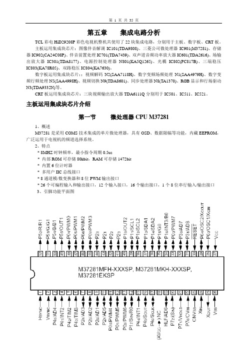
第五章集成电路分析TCL彩电HiD29208P彩色电视机整机共使用了22块集成电路,分别用于主板、数字板、CRT板。
主板运用集成块芯片:图像伴音解调IC101(TDA9808)、三菱公司微处理器IC901(M37281)、存储器IC902(CA24C08P)、伴音前置处理IC701(TDA7439)、双声道音频功率放大器IC601(TDA2616)、场输出放大器IC301(TDA8177)、电源控制处理器N801(KA5Q1265)、光耦IC802(PC817B)、三端稳压IC803(KA78R05)、双路稳压IC804(KA7630)。
数字板运用集成块芯片::视频解码N2(SAA7118H)、数字变频场频处理N1(SAA4979H)、数字变频行频处理N5(SAA4998H)、视频切换N9(TDA8601)、同步处理器N8(TA1370)、RGB显示和行场驱动N3(TDA9332N)等。
CRT板运用集成块芯片:三块视频输出放大器TDA6111Q分别用于IC501、IC511、IC521。
主板运用集成块芯片介绍第一节微处理器CPU M372811、概述M37281是采用COMS技术集成的单片微处理器,具有OSD、数据限幅等功能,内藏EEPROM,广泛运用于电视机的频道选择系统。
2、特点* 8MHZ时钟频率,最小指令周期0.5us* 内部ROM可存储80kbit,RAM可存储1472bit* 内置6位计时器* 多用户IIC总线接口* 8通道模/数变换器和8位PWM输出接口* 26个可编程输入和输出接口,12个输入接口,16个输出接口,1个8位串行输入/输出接口3、引脚功能平面图3、IC引脚功能说明第二节图像和伴音解调集成电路TDA98081、概述TDA9808是飞利浦公司生产地锁相环中频解调集成电路,广泛运用于电视机和多媒体前端作图像和伴音中频信号处理。
2、特点:* 5V供电* 可适用38.9MHz,45.75MHz和58.75MHz的中频。
- 1、下载文档前请自行甄别文档内容的完整性,平台不提供额外的编辑、内容补充、找答案等附加服务。
- 2、"仅部分预览"的文档,不可在线预览部分如存在完整性等问题,可反馈申请退款(可完整预览的文档不适用该条件!)。
- 3、如文档侵犯您的权益,请联系客服反馈,我们会尽快为您处理(人工客服工作时间:9:00-18:30)。
Symbol I2 I6 I1
V3L V5 V5L
V5H
Tj
Parameter Pin 2 Quiescent Current Pin 6 Quiescent Current Amplifier Input Bias Current
Pin 3 Saturation Voltage to GND Quiescent Output Voltage Output Saturation Voltage to GND
PIN CONNECTIONS (top view)
7 6 5 4 3 2 1
Tab connected to Pin 4
BLOCK DIAGRAM
HEPTAWATT (Plastic Package) ORDER CODE : TDA8172
NON-INVERTING INPUT OUTPUT STAGE SUPPLY OUTPUT GROUND FLYBACK GENERATOR SUPPLY VOLTAGE INVERTING INPUT
Value
Unit
35
V
60
V
+ Vs
+ Vs
V
– 0.5
2.5
A
3
A
2
A
100
mA
3
A
20
W
– 40, +150
°C
THERMAL DATA
Symbol Rth (j–c)
Parameter Thermal Resistance Junction-case
Max.
Value 3
Unit °C/W
ELECTRICAL CHARACTERISTICS (refer to the test circuits, VS = 35V, Tamb = 25oC unless otherwise specified)
Output Saturation Voltage to Supply
Junction Temperature for Thermal Shut Down
Test Conditions I3 = 0, I5 = 0 I3 = 0, I5 = 0 V1 = 1 V, V7 = 2 V V1 = 2 V, V7 = 1 V I3 = 20 mA Vs = 35V, Ra = 39 kΩ I5 = 1.2 A I5 = 0.7 A – I5 = 1.2 A – I5 = 0.7 A
VS
2
6
12kΩ
1
5
2V
7
4
V5
V7 Ra
5.6kΩ
8172-05.EPS
S1 : (a) V3L ; (b) V5L
8172-04.EPS
8172-06.EPS
3/5
元器件交易网
TDA8172
Figure 2 : AC Test Circuit
1 N4 0 0 1
VS
8172-07.EPS
8172-08.EPS - 8172-09.EPS
4/5
元器件交易网
PACKAGE MECHANICAL DATA : 9 PINS - PLASTIC HEPTAWATT
TDA8172
PM-HEPTV.EPS
Dimensions
A C D D1 E F F1 G G1 G2 H2 H3 L L1 L2 L3 L5 L6 L7 M M1 Dia.
+ VS
2
6
3
FLYBACK G E NE R ATOR
1 P OWER
AMPLIFIER 7
TDA8172
4
5
THE R MAL P ROTECTION
8172-01.EPS
YOKE
8172-02.EPS
May 1996
1/5
8172-01.TBL
元器件交易网
TDA8172
© 1996 SGS-THOMSON Microelectronics - All Rights Reserved
Purchase of I2C Components of SGS-THOMSON Microelectronics, conveys a license under the Philips I2C Patent. Rights to use these components in a I2C system, is granted provided that the system confo rms to
C1
C2
C3
0.1µF
470µF
D1
220µF
t fly
2
63
VREF
7
Iy
V7
GND
Viቤተ መጻሕፍቲ ባይዱ
R1
1
to
1 0kΩ
RT1 4.7kΩ
TDA8 1 7 2
4
5 C4
0.22µF
to Ly
24.6mH
R7
R6
1 .5 Ω
330Ω Ry
R3
R4
9.6Ω
IN
1 2 kΩ
C6
8 .2 kΩ
R2
4.7µF
C5
5 .6 kΩ
3 15.8 6.6
3.85
Min.
0.094 0.047 0.014 0.024 0.095 0.193 0.295 0.396
0.102 0.594 0.236
0.144
Inches Typ.
0.100 0.200 0.300
0.668 0.587 0.848 0.891
0.110 0.200
Max. 0.189 0.054 0.110 0.053 0.022 0.031 0.035 0.105 0.205 0.307 0.409 0.409
0.118 0.622 0.260
0.152
Information furnished is believed to be accurate and reliable. However, SGS-THOMSON Microelectronics assumes no responsibility for the consequences of use of such information nor for any infringement of patents or other rights of third parties which may result from its use. No licence is granted by implication or otherwise under any patent or patent rights of SGS-THOMSON Microelectronics. Specifications mentioned in this publication are subject to change without noti ce. This publication supersedes and replaces all information previously supplied. SGS-THOMSON Microelectronics products are not authorized for use as critical components in life support devices or systems without express written approval of SGS-THOMSON Microelectronics.
Figure 3 : Mounting Examples
Between the heatsink and the package it is better to insert a layer of silicon grease, to optimize the thermal contact ; no electrical isolation is needed between the two surfaces, since the tab is connected to Pin 4 which is ground.
ABSOLUTE MAXIMUM RATINGS
Symbol VS
V5, V6 V3
V1, V7
Supply Voltage (pin 2) Flyback Peak Voltage Voltage at Pin 3 Amplifier Input Voltage
Parameter
Io Io Io I3 I3 Ptot Tstg, Tj
the I2C Standard Specifications as defined by Philips.
SGS-THOMSON Microelectronics GROUP OF COMPANIES Australia - Brazil - Canada - China - France - Germany - Hong Kong - Italy - Japan - Korea - Malaysia - Malta - Morocco
元器件交易网
TDA8172
TV VERTICAL DEFLECTION OUTPUT CIRCUIT
... POWER AMPLIFIER FLYBACK GENERATOR THERMAL PROTECTION
DESCRIPTION The TDA8172 is a monolithic integrated circuit in HEPTAWATTTM package. It is a high efficiency power booster for direct driving of vertical windings of TV yokes. It is intended for use in Color and B & W television as well as in monitors and displays.
