新型风杆说明书
升降杆的使用说明书

升降杆的使用说明书一、升降杆的使用范围各种通讯设备,照明灯、摄像头.夜视仪、避宙针等设备的架设支探。
尤其适用机动性较强.频繁移动的各种项目。
二、升阵杆的适用环境工作温度±55℃.最大抗风30m/s(安装基础牢固和拉线状态)、平坦坚实地面。
三、升降杆的选用条件1、确定总升起高度,闭合高度,承载重量,迎风面积。
2、确定地面安装,车外安装或车内安装。
四、结构特征及工作原理1、结构紧凑,由底座、杆体、手摇把组成.外观无多余物.便于安装,杆体用高强度铝合金,往复活动件用不锈纲制造.避免锈蚀影响往复活动.2、工作原理是由手摇轴、伞齿轮、丝杠、丝母、钢丝绳组合传递动力.达到升降目的。
注:郑州万佳防雷有限公司生产的手动升降杆.仅IA型是逐节升降.其余型号均为“倍伸机构”.即各节活动杆同时升降,速度快,升起后可见钥丝绳外露.五、拉线系统综合介绍1.拉线系统由拉线盒(包括拉线镇、钢丝绳、挂钩等)和地钉组成.2.拉线盒有大小两种.按拉线分为一、二、三.四层,共有八种。
3.拉线盒由棘轮机构自锁原理设计而成。
通过操纵锁销柄,播动拉线盒摇把.实现钢丝拉线的收放拉紧,实现固定升降杆目的。
4.拉线盒的配备是报据升降杆承重大小和升起高度来选择。
5.拉线盒的配备增强了升降杆的刚性、稳定性、扰伏倒性。
也是在地面上使用的升降杆用于固定锁住固定管(最外部的杆体)实现对升降杆升起后锁住固定的方法。
注:地面使用的升降杆.必须用拉线固定锁住“固定管”才能升降。
6,拉线系统的安装使用:以ⅡA型地面使用升降杆配备三层拉线盒为例进行介绍.各型升降杆均按此顺序操作。
(1)确定升降杆安装位里。
(2)确定地钉位置,地钉挂环正对升降杆方向,钉下地钉。
(3)将三个拉线盒挂钩分别挂在三个地钉挂环上。
(4)拔起锁销柄并旋转90o,使锁销柄凸高位气动升降桅杆OK-QD3-20SJ系列升降桅杆是为车载移动设备专业设计的升降装置。
桅杆固定于车厢内部或者车体周边,垂直地将如灯具设备、摄像设备等举升高空,实现客户预定功能。
3米气象站风杆技术指标
3米气象站风杆技术指标1.引言气象站是用来监测和记录气象信息的设备。
其中,风杆是气象站中非常重要的组成部分,它用于测量气象站所处位置的风速和风向。
本文将介绍3米气象站风杆的技术指标,以帮助读者更好地了解其功能和性能。
2.基本信息-高度:3米-材质:不锈钢-安装方式:可固定在地面或安装在适当的支撑结构上3.抗风能力3米气象站风杆的抗风能力是衡量其稳定性和可靠性的重要指标。
具体的抗风能力要求如下:-最大持久风速:不少于60米/秒-最大瞬间风速:不少于80米/秒-抗倾斜能力:倾斜角度不超过5度4.弯曲与颤振为了保证风杆的准确测量和长期稳定性,其弯曲和颤振必须控制在合理范围内。
以下是相关技术指标:-最大弯曲幅度:不超过10mm-最大颤振振幅:不超过5m m5.集成传感器安装3米气象站风杆设计时需要考虑传感器的安装方式和位置,以便正确测量风速和风向。
以下是相关要求:-传感器安装位置:距离地面2.5米处-高度角度误差:不超过1度6.阻尼器为了减少风杆受到的外部震动和干扰,阻尼器是必不可少的。
以下是阻尼器的相关要求:-阻尼系数:不小于0.7-阻尼器类型:液压阻尼器7.防腐蚀性能由于气象站通常设置在户外环境中,3米气象站风杆必须具备良好的防腐蚀性能,以延长其使用寿命。
相关要求如下:-防腐材料:不锈钢304-耐腐蚀性能:符合A S TM G85标准,盐雾测试结果不超过500小时8.总结本文介绍了3米气象站风杆的技术指标,包括抗风能力、弯曲与颤振、集成传感器安装、阻尼器和防腐蚀性能等方面。
这些技术指标的达到与否直接关系到气象站观测数据的准确性和可靠性。
希望通过本文的介绍,读者能更好地了解3米气象站风杆的重要性和相关技术指标。
科禄格风机说明书
Type of grease Alvania Grease #3 SKF Grease LGMT 3 SKF Grease LGMT 3
!"#
• !"#$% ! KRUGER !"# $%&'(
• •
!"#$%&'()*+ !2 !"#$%&'()*+,!"#$%&'()*+,-./ !"# !"#$%&'()*
- 11 -
!"#$%& ! !"#$%&' !"#$%&'()*+ !"#$%&'()*+
Type of bearing NSK Deep Groove Ball Bearing SKF Deep Groove Ball Bearing SKF Spheriodical Roller Bearing
- 13 -
- 14 -
KRUGER GROUP (VENTILATION)
SINGAPORE
Kruger Ventilation Industries Pte Ltd
No. 17, Tuas Avenue 10 Singapore 639141 Tel. +65 68611577 - Fax +65 68613577
Turning Vanes
好
!""#
Rotation
Length of straight duct
( at least 3 equivalent duct Ø )
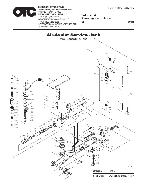
EISENHOWER DRIVE 1507B655 5吨空气助力杆架说明书
92
105
104 91
103
90
89
102
88
101
87
100
86
V
85
99
84
83
98
82
97Leabharlann 819679 80
79 30
28
29 28 27
26 108
K J
I
43 42
H
44
41
40
46
37
39
45
38
44
P 37
36
35 34 33 32 31
7 6
8
51 50
49
48
47
L
M
NP
58
Q
L R
531864 Release Valve Kit 47 1 Steel ball 48 1 O-ring 49 1 O-ring 50 1 Release valve rod 51 1 Pin
Parts List & Operating Instructions
Item No. Qty. Description
565766 Air Motor Seal Kit 28 2 Washer 29 1 O-ring 32 1 Sealing washer 33 1 O-ring 34 1 O-ring retainer 37 2 Oil filler plug 42 1 Sealing washer 45 1 Copper washer 48 1 O-ring 49 1 O-ring 56 2 O-ring 57 2 Washer 79 2 Copper washer 80 1 Oil valve assy 81 1 Nylon gasket 83 1 Oil seal 84 1 Washer 85 1 Copper washer 96 2 O-ring 98 2 O-ring 101 1 Air seal 102 2 O-ring 103 1 O-ring 106 2 O-ring J 1 Copper washer V 3 O-ring W 2 Ring
黑鹰自动汽车50吨气缸杆说明书
Air Hydraulic Bottle Jack Operating Instructions & Parts ManualModel CapacityBH2500 50 TonSFA Companies10939 N. Pomona Ave. Kansas City, MO 64153******************************SAFETY and GENERAL INFORMATIONSave these instructions.For your safety read, understand, and follow the information provided with and on this jack. The owner and operator of this equipment shall have an understanding of this jack and safe operating procedures before attempting to use. The owner and operator shall be aware that use and repair of this product may require special skills and knowledge. Instructions and safety information shall be conveyed in the operator's native language before use of this jack is authorized. If any doubt exists as to the safe and proper use of this jack, remove from service immediately.Inspect before each use.Do not use if broken, bent, cracked, or damaged parts (including labels) are noted. Any jack that appears damaged in any way, operates abnormally or is missing parts, shall be removed from service immediately and the manufacturer notified. If you suspect that the jack was subjected to a shock load (a load dropped suddenly, unexpectedly upon it), immediately discontinue use until the jack has been checked by a factory authorized service center (contact distributor or manufacturer for list of Authorized Service Centers). It is recommended that an annual inspection be done by qualified personnel. Replace worn or damaged parts with Blackhawk authorized replacement parts only. Labels and owner’s manuals are available from manufacturer.PRODUCT DESCRIPTIONBlackhawk Automotive Air Actuated Hydraulic Bottle Jack is designed to lift, not support, rated capacity loads consisting of one end of a vehicle. Immediately after lifting, the load must be supported by a pair of appropriately rated jack ***************************************************************************************** air pressure is required to raise rated capacity load.Never use hydraulic jack as a stand alone device. After lifting, immediately support the lifted loadwith a pair of appropriately rated jack stands.PREPARATIONBefore Use1. Verify that the product and the application are compatible, if in doubt contact Customer Support (816)891-6390.2. Before using this product, read the operator's manual completely and familiarize yourself thoroughly with theproduct, its components and recognize the hazards associated with its use.3. Assemble handle, ensure spring clips align with slots.4. To familiarize yourself with basic operation, use the notched end of provided handle to engage and turn the releasevalve:a. Clockwise until firm resistance is felt to further turning. This is the ‘CLOSED’ release valve position used toraise the ram plunger.b. Counter-clockwise, but no more than 1/2 turn from the closed position. This is the ‘OPEN’ release valveposition used to lower the ram plunger.5. With ram fully retracted, locate and remove the oil filler screw. Connect air hose to lift control valve, then squeezelift control valve to operate pump for few seconds. This will help release any pressurized air, which may be trapped within the reservoir. Ensure the oil level is just below the oil filler hole. Reinstall the oil filler screw.6. Pour a teaspoon of good quality, air tool lubricant into the air supply inlet of the lift control valve. Connect to airsupply and operate for 3 seconds to evenly distribute lubricant.7. This product is equipped with the popular 1/4" NPT air coupler. When installing a different air coupler of yourchoice, ensure that thread tape or compound is used when servicing connections. To ensure dependable, trouble free operation an inline air dryer and oiler is recommended.8. Check that the pump operates smoothly before putting into service. Replace worn or damaged parts and assemblieswith Blackhawk Automotive authorized replacement parts only.Bleeding / Venting Trapped AirWith the release valve in the OPEN position (4b above) and with ram plunger fully lowered, locate and remove the oil filler screw. Squeeze lift control valve to operate pump for few seconds. This will help release any pressurized air which may be trapped within the reservoir. Oil level should be even with the bottom of the oil filler hole. Reinstall the oil filler screw.SPECIFICATIONSModel Capacity Base Size(L x W)SaddleDiameterMin.HeightMax.HeightHydraulicLiftVolumeHyd. OilNetWeightBH250050 Ton10 7/8" x 7 3/8" 2 1/2"12"19"7"1650 mL129 lb.Figure 1 - BH2500 NomenclatureOPERATIONRaising the Ram Plunger1. Assemble handle, ensure that spring clips align with slots.2. Place vehicle in the park, with emergency brake on and wheel securely chocked to prevent inadvertent vehiclemovement.3. Locate and close release valve by turning handle clockwise until firm resistance is felt to further threadengagement.4. Verify lift point, center jack saddle under lift point.5. Squeeze the lift control valve in order to raise saddle to contact lift point. To lift, continue pumping until load reachesdesired height.6. Immediately secure lifted load with appropriately rated jack stands.Use only the handle provided by jack manufacturer. The handle provided with this jack will safely engage STOP, discontinue use of the jack until a factory replacement handle can be acquired.LoweringMake certain that all personnel are clear of the load before lowering.Control the rate of descent of the load at all times. The more you open the release valve, the faster the load descends.1. Raise load high enough to clear the jack stands, then carefully remove jack stands (always used in pairs).2. Slowly turn the handle counter-clockwise, but no more than 1/2 turn. If the load fails to lower:a. Use another jack to raise the vehicle high enough to reinstall jack stands.b. Remove the affected jack and then the stands.c. Lower the load by turning the release valve counter-clockwise, but no more than 1/2 turn.3. After removing jack from under the load, push ram and handle sleeve down to reduce exposure to rust andcontamination.on areas of the vehicle as specified by the vehiclemanufacturer.MAINTENANCEImportant:Use only good grade hydraulic jack oil. Avoid mixing different types of fluid and Never use brake fluid, turbine oil, transmission fluid, motor oil or glycerin. Improper fluid can cause failure of the jack and the potential for sudden and immediate loss of load. We recommend Hein-Werner HW93291 or equivalent.Adding oil1. With ram plunger fully lowered and air supply disconnected, set jack in its upright, level position. Remove oil fillerscrew.2. Fill with oil until just below the rim of the oil filler hole. Reinstall the oil filler screw.Changing oilFor best performance and longest life, replace the complete fluid supply at least once per year.1. With ram plunger fully lowered and air supply disconnected, remove the oil filler screw.2. Lay the jack on its side and drain the fluid into a suitable container.Note: Dispose of hydraulic oil in accordance withlocal regulations.3. Fill with oil until just below the rim of the oil filler hole. Reinstall the oil filler screw.LubricationAir pump should be internally lubricated before each use. Use good quality air tool lubricant. If no inline oiler is used, pour a teaspoon of air tool oil into the air control valve inlet. Operate the jack with air pressure to fully distribute the oil inside the air motor.CleaningPeriodically check the ram for signs of rust/corrosion. Clean as needed and wipe with oily cloth.Note: Never use sandpaper or abrasive material on ram surface!StorageWhen not in use, store the jack with ram plunger fully retracted and air supply disconnected.TROUBLESHOOTINGSymptom Possible Causes Corrective ActionJack will not lift load• Release valve not tightly closed• Overload condition• Air pressure inadequate • Ensure release valve tightly closed • Remedy overload condition •Ensure adequate air pressureJack will lift, but not maintain pressure •Release valve not tightly closed• Hydraulic unit malfunction•Ensure release valve tightly closed• Discontinue use, contactBlackhawk Technical ServiceJack will not lower after unloading• Reservoir overfilled• Drain fluid to proper levelPoor lift performance• Fluid level low•Air trapped in system • Ensure proper fluid level•With ram fully retracted, remove oil filler screw to let pressurized air escape. Reinstall oil filler screwWill not lift to full extension• Fluid level low• Ensure proper fluid levelREPLACEMENT PARTS(refer to page 6 & 7)Not all components of the jack are replacement items, but are illustrated as a convenient reference of location and position in the assembly sequence. When ordering parts, give Model number, serial number and parts description. Call or write for current pricing: SFA Companies, 10939 N. Pomona Ave. Kansas City, MO 64153, U.S.A.Tel:(816)891-6390Fax:(816)891-6599E-Mail:******************************Replacement Parts Illustration for Model BH2500Figure 2 - Model BH2500 Replacement Parts IllustrationReplacement Parts List for Model BH2500Item Part#Description Qty1*O-ring12N/A Top Nut13*O-ring14N/A O-ring15N/A Filler screw16* (324-4-1900-208)Filler Screw Assembly17N/A Reservoir18601-4-0080-009Spring Pin29244-6-1806-205Carry Handle210*Oil Seal111N/A Ram Plunger112244-6-1205-108Collar113244-6-1204-207Snap Ring214N/A Ram Bearing115*U-cup116N/A Cylinder117*O-ring118532-8-0050-024Filter119N/A Base120238-6-1701-403Release Valve121*Oil Seal122601-7-0008-009Steel Ball123503-9-0067-103Stud124644-1-0080-031Screw125A20-4-1500-106Hyd. Cartridge126A27010-0001Air Motor127A27010-0002Air Inlet Swivel128A20060-0007Lift Control Valve129A20060-0006Air Hose only130A20060-0005Air Hose Assembly131181-3-2100-103Handle Assembly132A270-01100-000Piston, Air Motor1(*)A50-3-9905-100Repair Kit1(*) - parts included in Repair KitN/A - parts not available, replace entire unitONE YEAR LIMITED WARRANTYFor a period of one (1) year from date of purchase, SFA Companies will repair or replace, at its option, without charge, any of its products which fails due to a defect in material or workmanship under normal usage. This limited warranty is a consumer's exclusive remedy.Performance of any obligation under this warranty may be obtained by returning the warranted product, freight prepaid, to SFA Companies Warranty Service Department, 10939 N. Pomona Ave., Kansas City, MO 64153.Except where such limitations and exclusions are specifically prohibited by applicable law,(1) THE CONSUMER'S SOLE AND EXCLUSIVE REMEDY SHALL BE THE REPAIR OR REPLACEMENT OF DEFECTIVE PRODUCTS AS DESCRIBED ABOVE.(2) SFA Companies SHALL NOT BE LIABLE FOR ANY CONSEQUENTIAL OR INCIDENTAL DAMAGE OR LOSS WHATSOEVER.(3) ANY IMPLIED WARRANTIES, INCLUDING WITHOUT LIMITATION THE IMPLIED WARRANTIES OF MERCHANTABILITY AND FITNESS FOR A PARTICULAR PURPOSE, SHALL BE LIMITED TO ONE YEAR, OTHERWISE THE REPAIR, REPLACEMENT OR REFUND AS PROVIDED UNDER THIS EXPRESS LIMITED WARRANTY IS THE EXCLUSIVE REMEDY OF THE CONSUMER, AND IS PROVIDED IN LIEU OF ALL OTHER WARRANTIES, EXPRESS OR IMPLIED.(4) ANY MODIFICATION, ALTERATION, ABUSE, UNAUTHORIZED SERVICE OR ORNAMENTAL DESIGN VOIDS THIS WARRANTY AND IS NOT COVERED BY THIS WARRANTY.Some states do not allow limitations on how long an implied warranty lasts, so the above limitation may not apply to you. Some states do not allow the exclusion or limitation of incidental or consequential damages, so the above limitation or exclusion may not apply to you. This warranty gives you specific legal rights, and you may also have other rights, which vary from state to state.SFA Companies Array 10939 N. Pomona Ave. Kansas City, MO 64153816-891-6390******************************。
基恩士sj离子风棒说明书

基恩士sj离子风棒说明书基恩士(Inno-Technology)是一家日本的研发、生产、销售及服务于全球医疗器械行业的公司。
基恩士(Sinno-Technology)总部位于日本新潟县,在中国、韩国等国家均设有分公司。
自199年成立以来,基恩士始终致力于开发全球市场,凭借卓越的品质和技术,在世界各地拥有数百家销售服务机构。
而基恩士Sinno-Technology还是一个“具有高创新能力、具有全球竞争力和持久竞争力的中国企业”。
1.使用前将样品放在干燥的环境中,然后在距离样品1 cm 处进行测量;在风管内部放置一支长为2 cm左右的电,接上充电电源。
根据使用说明定期进行清洗,确保无杂质。
使用后将电容量表取下,将样品放入回风口(温度为60℃左右)。
电底部将离子线绕成螺旋状;使用前将电移至远离吹风口处。
2.如果样品的湿度较大,请使用本仪器,然后再检查是否有干燥的现象,如果发现该现象,请及时清除;如果发现湿度过大,请使用本仪器,然后再检查是否有干燥的现象,如果发现该现象,请及时清除;如需再次使用本仪器,请重复上述步骤。
本仪器一般使用干燥的软纸盒包装,如果打开后,有水珠或滴水现象,请立即用水冲洗干净;如使用蒸馏水或纯净水,请按下“样品”键;如在使用纯净水时,有水珠滴落的现象,可用棉签擦拭干净;如样品中有水珠、液体或其他物质时,请先用棉签擦干净,然后再用纯净水冲洗干净和干燥。
3.在距离样品1 cm处测量的温度通常不会超过100℃,因此使用本仪器时应将室温保持在40℃左右;如果需要将样品放置在离子风中进行测量,则应保证距离样品1 cm处没有其他物体的干扰。
而基恩士公司作为世界上最早进行离子风棒研发的企业之一,一直以来都在为用户提供优质的产品。
对于新产品的研发,基恩士公司也一直保持着高标准的态度和方法。
除此之外,为了确保基恩士公司在离子风棒领域内所具备的优势与经验,在过去数年中基恩士Sinno-Technology一直积极和其他地区之间进行着息交流。
YGY-FSXY1 风速风向仪 使用说明书
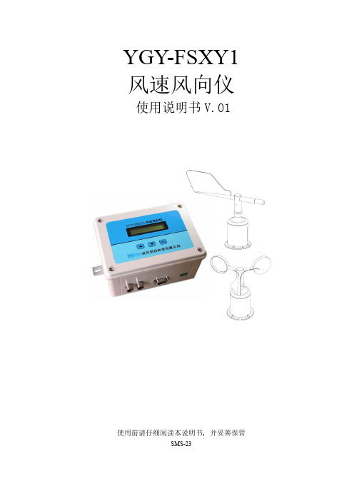
YGY-FSXY1 风速风向仪使用说明书V.01使用前请仔细阅读本说明书,并妥善保管SMS-23感谢您选购本公司产品!由于本公司产品不断改进,您所购买的产品可能与说明书图示有所有不同,恕不另行通知。
请以实物为准。
目录1、产品简介............................................................................................................................ - 2 -2、功能特点............................................................................................................................ - 2 -3、技术参数............................................................................................................................ - 2 -4、仪表接口说明.................................................................................................................... - 3 -5、仪表菜单按键操作说明.................................................................................................... - 3 -5.1按键功能介绍............................................................................................................ - 3 -5.2菜单操作流程............................................................................................................ - 3 -6、风向传感器安装定南........................................................................................................ - 4 -7、风速报警功能(选配).................................................................................................... - 5 -8、仪器与电脑软件的连接.................................................................................................... - 5 -9、产品清单............................................................................................................................ - 5 -10、异常现象的分析及解决方法.......................................................................................... - 6 -11、注意事项.......................................................................................................................... - 6 -12、支架安装方法.................................................................................................................. - 6 -13、附表2:风向16方位图................................................................................................. - 6 -14、联系方式.......................................................................................................................... - 6 -1、产品简介YGY-FSXY1风速风向仪是用于测量并记录大气中风速与风向的气象仪器。
10米风杆安装说明
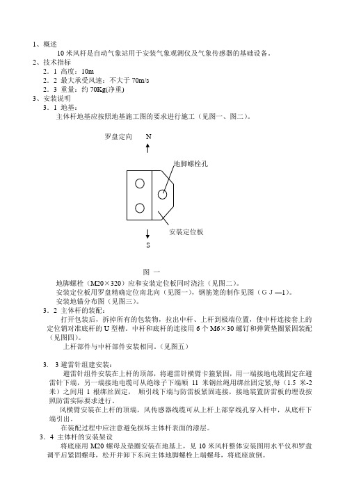
1、概述10米风杆是自动气象站用于安装气象观测仪及气象传感器的基础设备。
2、技术指标2.1 高度:10m2.2 最大承受风速:不大于70m/s2.3 重量:约70Kg(净重)3、安装说明3.1 地基:主体杆地基应按照地基施工图的要求进行施工(见图一、图二)。
罗盘定向N安装定位板S图一地脚螺栓(M20×320)应和安装定位板同时浇注(见图二)。
安装定位板用罗盘精确定位南北向(见图一),钢筋笼的制作见图(GJ—1)。
安装地锚分布图(见图三)。
3.2 主体杆的装配:打开包装后,拆掉所有的包装物,拉出中杆、上杆到极端位置,使中杆连接套上的定位销对准底杆的U型槽。
中杆和底杆的连接用6个M6×30螺钉和弹簧垫圈紧固装配(见图四)。
上杆部件与中杆部件安装相同。
(见图五)3. 3避雷针组建安装:避雷针组件安装在上杆的顶部,将避雷针横臂卡箍紧固,用一端接地电缆固定在避雷针下端,另一端接地电缆可从绝缘子下端顺11米钢丝绳用绑丝固定紧,每(1.5米-2米)之间用1根绑丝固定,顺引线下端与防雷板紧固连接,接地装置防雷板的埋设按照防雷实际要求进行。
风横臂安装在上杆的顶端,风传感器线缆可从上杆上部穿线孔穿入杆中,从底杆下端引出。
在装配过程中应注意避免损坏主体杆表面的漆层。
3.4 主体杆的安装架设将底座用M20螺母及垫圈安装在地基上,见10米风杆整体安装图用水平仪和罗盘调平后紧固螺母,松开并卸下东向主体地脚螺栓上端螺母,将底座放倒。
将主体管呈东西向放倒在地基旁,将底杆插入底座,用两个M8×30螺栓和弹簧垫圈紧固装配。
调整好风横臂的南北向,安装好钢丝拉绳以后,就可以竖立主体杆,并将东向的地脚螺栓上端螺母和弹簧垫圈紧固装配。
最后在主体地脚螺栓上加上防护帽。
3.5拉绳和安装一组拉绳其中有1根钢丝绳上加1个绝缘子,两端各用两个绳夹紧固。
两组拉绳卡箍按照安装图10米风杆整体图的要求分别固定在上杆A处和中杆B处。
3000-LB 侧风扭风平台杆说明书

3000-L B.S I D E-W I N D I N GS Q UA R E J A C KOWNER’S MANUALWARNING: Read carefully and understand all INSTRUCTIONS before operating. Failure to follow the safety rules and other basic safety precautions may result in serious personal injury.Thank you very much for choosing an ULTRA-TOW TM Product! For future reference, please complete the owner’s record below:Model: _______________ Purchase Date: _______________Save the receipt, warranty and these instructions. It is important that you read the entire manual to become familiar with this product before you begin using it.This product is designed for certain applications only. The distributor cannot be responsible for issues arising from modification. We strongly recommend this product not be modified and/or used for any application other than that for which it was designed. If you have any questions relative to a particular application, DO NOT use the product until you have first contacted the distributor to determine if it can or should be performed on the product.For technical questions please call 1-800-222-5381.INTENDED USEA trailer jack makes coupling and uncoupling from the hitch ball easier.TECHNICAL SPECIFICATIONS & PACKING LISTItem DescriptionCapacity 3000 Lbs. (1364 kg)Travel 15in. (38cm)Working range 15in. – 30in. (380 - 760mm)Pin size9/16in. (14mm)GENERAL SAFETY RULESWARNING: Read and understand all instructions. Failure to follow all instructions listed below may result in electric shock, fire and/or serious injury.WARNING:The warnings, cautions, and instructions discussed in this instruction manual cannot cover all possible conditions or situations that could occur. It must be understood by the operator that common sense and caution are factors which cannot be built into this product, but must be supplied by the operator.SAVE THESE INSTRUCTIONSWORK AREA·Keep work area clean, free of clutter and well lit.Cluttered and dark work areas can cause accidents.·Keep children and bystanders away while using a trailer jack. Distractions can cause you to lose control, so visitors should remain at a safe distance from the work area.·Be aware of all power lines, electrical circuits, water pipes and other mechanical hazards in your work area, particularly those hazards below the work surface hidden from the operator’s view that may be unintentionally contacted and may cause personal harm or property damage.·Be alert of your surroundings. Using a trailer jack in confined work areas may put youdangerously close to cutting tools and rotating parts.PERSONAL SAFETY·Use personal protective equipment. Always wear eye protection. Safety equipment such as dust mask, non-skid safety shoes, hard hat, or hearing protection used for appropriateconditions will reduce personal injuries.·Do not overreach. Keep proper footing and balance at all times. This enables better control of the trailer jack in unexpected situations.·Dress properly. Do not wear loose clothing or jewelry. Keep your hair, clothing and gloves away from moving parts. Loose clothes, jewelry or long hair can be caught in moving parts.TOOL USE AND CARE·Use on smooth, flat surfaces only.·Do not force the trailer jack. Do not attempt to lift more than the 3000-lb. maximum lifting capacity of this jack.·Store idle jacks out of the reach of children and do not allow persons unfamiliar with the jack or these instructions to operate it.·Maintain your trailer jack. Check for misalignment or binding of moving parts breakage of parts and any other condition. If damaged, have the jack repaired before use.Use the jack and accessories in accordance with these instructions, taking into account the working conditions and the work to be performed. Use of the trailer jack for operations different from those intended could result in a hazardous situation.OPERATIONWARNING:Do not use blocks to increase ground clearance —the trailer can tip and fall. Replace jack if worn, damaged or not operating freely.Pivot Tube Weld-on Mounting1. All welding operations must be performed by an AWS certified welder.2. Place the weld-on pivot tube against the trailer tongue and affix using a fillet weld all round(Fig. 1).3. Assemble the jack to the pivot tube by placing the jack over the pivot tube and secure with pin(supplied).4. Check to make sure Jack swings freely and does not interfere with trailer light cables or withcoupler.Figure 11. Turn handle clockwise to raise.2. Turn handle counterclockwise to lower.MAINTENANCE·Maintain your trailer jack. Before each use, inspect the general condition of the jack. Check for loose hardware, misalignment or binding of moving parts, cracked or broken parts, damaged electrical wiring, and any other condition that may affect its safe operation.·Keep all moving parts lightly lubricated to prevent corrosion.·After use, wipe external surfaces of the tool with clean cloth.DIAGRAM & PARTS LISTPart# Description Qty. Part# Description Qty.1 Cover 1 12 Bearing Cover 12 Handle Gear 1 13 Washer 13 Threaded Rod Gear 1 14 Pin 14 Pin 1 15 Bearing Cover 15 Screw 1 16 Bearing 16 Chain 1 17 Washer 17 Grease Zerk 1 18 Threaded Rod 18 Aluminum Rivet 1 19 Nut 19 Pin 1 20 Inner Tube 110 Outer Tube 1 21 Weld-on Pivot Tube 111 Handle 1For replacement parts and technical questions, please call 1-800-222-5381.WARRANTYOne-Year Limited WarrantyDistributed byNorthern Tool + Equipment Co., Inc..Burnsville, MN 55306-6936Made in China。
窗户撑杆伸缩风撑
窗户撑杆伸缩风撑杆The telescopic wind support rod of the window is a kind of support rod used to support the window. It is usually made of aluminum alloy or stainless steel. It is usually used in the windows of high-rise buildings. It is usually composed of a base, a telescopic rod and a windproof cap.窗户撑杆伸缩风撑杆安装非常简单,只需将撑杆放置在窗台上,即可完成安装。
它可以有效地防止窗户被大风吹坏。
它可以在受风吹拂时,将窗户拉回到正常位置,从而使窗户不受风刮伤。
The installation of the telescopic wind support rod of the window is very simple, just put the support rod on the windowsill, and the installation can be completed. It can effectively prevent the window from being blown away by strong wind. It can pull the window back to its normal position when it is blown by the wind, so that the window is not scratched by the wind.窗户撑杆伸缩风撑杆具有结构简单、安装简单、安装安全、使用可靠的特点。
它的伸缩部分可以根据窗户的大小和高度进行调节,使撑杆更加牢固。
sunje离子风棒说明书

sunje离子风棒说明书
离子风棒是一种固定风量、小范围的离子消除设备,一般都是使用直流技术,它的离子风覆盖面积大,适用于印刷、电子、塑料等行业,它的风量不可调节,可平衡离子的数量。
一、光电感应器过于灵敏,可用配带的塑料螺丝刀旋转感应器上的旋孔顺时针调节。
二、把进气管连接在离子风棒的进气口上。
三、离子风棒输出5.6KV高电压,但电流只有80uA,当接触离子针时会有微弱电击感,为保证**和保护离子针,请不要接触离子针。
四、离子风棒的接地端子接地,也可配置3脚插头而不需另外接地。
五、打开离子风棒上的电源开关,设备处于等待状态,当光电感应器感应到工作人员时,内置气阀打开,同时电源接通,设备开始工作,此时电源指示灯和离子指示灯亮,表示正常。
智能风扇速度报警杆说明书

The driving force SmartFan®TachStripFan Speed AlarmCONTROLPart NumberSupply VoltageRangeAlarm UnitsPer StripMaximum InputCurrentMaximum OutputCurrent to any fan015B125-F5 to 25 VDC14.0 Amps 4.0 Amps015B625-F6H109-F1Hardware PackSPECIFICATIONS1per alarm unitNote: Maximum operating temperature is 65°CSmartFan TachStrip is a modular fanspeed alarm that ac c epts ta c hom e t er(Hall Effect) pulses from DC or AC fans orblow e rs. TachStrip monitors these pulsesand generates fail u re alarms if air mov e rspeed drops below a preset trigger speed.TachStrip com p ris e s a strip of 6 individualalarm units bused to g eth e r. The websep a r at i ng units can be cut to providestrips to handle any quan t i t y of fans.Each unit monitors one air mover andprovides alarm out p uts for that air mover.The bus distributes power to each unit andOR’s alarm signals from each unit topro v ide a single alarm out p ut if any airmover should fail. Each alarm unit hasthree out p uts used to drive a logic circuit,LED, or piezo alarm.FEATURES•Accepts open collector or voltage source pulses from nearly any DC orAC fan or blower•6 alarm unit strips are easily separated to monitor any quantity of fans•Distributes power to DC air movers through same connector used tosense pulses•Separate alarm outputs are provided for each fan•Alarm channels are OR’d providing a single alarm if any fan fails•Trigger speed is adjustable by jumper to 1500, 2500, or 4000 PPM•Permissible power supply voltage is 5.0 VDC minimum to 25.0 VDCmaximum•RoHS (6/6) compliantNormally Closed (NC) Alarm Output Closed above trigger speedand will sink 4 mA at 0.4 VDC or less. Open below trigger speed andwill ac c ept up to 30 VDC. Referenced to fan negative terminal. Ap p liesnominal 12 mA to an LED connected from NC to L.Normally Open (NO) Alarm Output Open above trigger speedand will accept up to 30 VDC. Closed below trigger speed and will sink4 mA at 0.4 VDC or less. Referenced to negative fan terminal. Ap p liesnominal 12 mA to an LED connected from NO to L. Ap p lies nominalpower supply voltage to a piezo alarm con n ect e d from NO to P.OR’d (OR) Alarm Output OR’d with all other alarm units inTachStrip. Other char a c t er i s t ics identical to NO alarm output.CONTROL RESOURCESINCORPORATEDE-Mail:******************** Web: INSTALLATIONMountingFor TachStrip part n umber 015B625-F to be u sed as separate alarms, cut the web separating alarm units at the designed location with ordinary cutting pliers.J1 – Fan Power and Tachometer Input J2 – Supply Power and Alarm Outputs J3 – Trigger Speed SettingFigure 1. Wiring diagram. (Dotted lines represent connections to alternative wiring configurations.)DC Fan ConnectionFor three wire DC fans operating at supply voltages between 5.0 and 25.0 VDC, TachStrip distributes power to the fa n in addition to accepting tachometer pulses from the fan. Connect the fan wires to J1. Fan wi res are usually color coded with red for +, bla ck for - and white or yellow for A (alarm).The maximum current that can be di stributed to the fan via header J1 is 4.0 Amp s. Normally it is nece ssary to connect power to o nly one J2 he ader in a TachStrip (015B625-F). However, t his connector is rated at 4.0 Amps maximum. If the total current u sed by all DC fans powered by TachStrip exceeds 4.0 Amps, p ower connections should be made at additional + and - pins.DC Fan Tachometer Signal CompatibilityFor most fans, the amplitude of tacho meter pulses will be equal to the voltage applied to the fan (e.g. a 12 VDC fan usually generates 12 VDC ta chometer pulses). However, some fans g enerate tachometer pulses at a lower voltage (e.g. 5 VDC pulses from a 12 VDC fan). In these cases, TachStrip must be powered with a voltage equal to o r less th an the amplitude of the pulses generated by the fan and it cannot therefore, di stribute power to the fans.DC Fans Operating Above 24 VDCThough the maximum voltage that can be applied to TachStrip is 25 VDC, it can be used with fans operating at higher voltages. In thi s case, it do es not distribute power to the fans. A supply voltage equal to or less than the amplitude of the p ulses supplied by the fans is used to power TachStrip.Connect the negative fan lead to J1:- and the fan tachometer pulse lead to J1:A. No connection is made to J1:+.AC Fan Alarm MonitoringTachStrip cannot distribute AC power to an AC fan. AC fans usually have 5 wires, 2 for powe r and 3 for t he tachometer pulse circuit. Connect the AC fan power leads to the rated source of power. Conne ct the three tachometer pulse leads to J1. TachStrip distributes power to run the ta chometer pulse circuits within the fans. Apply a DC voltag e as specified by the fan manufacturer for the tachometer pulse circuits at J2.OPERATIONSettings (J3)Trigger Speed (W A ): Use this jumper to set the t rigger speed. Select a trigger that is 40 to 50% of rated speed.Position 15 = 1500 PPMPosition 25 = 2500 PPM (Factory Setting) Position 40 = 4000 PPMSince fan ta chometer circuits are designed with one, two, or even more pul se outputs per revolution, settings are listed in pulses per minute (P PM) rather than revolutions per minute (RPM). Given the fan’s rated speed (W) and number of pulses per revolution (N), use the following formula to select the trigger speed (W A ):W A = W x N x 0.4For example, a 3300 RPM fan with two pulses per revolution would have an trigger speed (W A ) ofW A = 3300 RPM x 2PPR x 0.4 = 2640 RPMSince the 2500 PPM trigger is clo sest, set jumper J3 to the “25” position.CONTROL RESOURCESINCORPORATEDE-Mail:******************** Web: Alarm Outputs (J2)Three alarm circuits a re located on header J2. All circuits are non-isolated, have the same electrical ratings, and are referenced to board ground found at J2:-.Alarm Output Above Speed Trigger Below Speed Trigger Power Removed from Unit NC Short to Ground Open Circuit Open Circuit NO Open Circuit Short to Ground Open Circuit OROpen CircuitShort to GroundOpen CircuitTable 1. Alarm output logicPower for a LED alarm indication is provided by Pin J2:L via an internal 12 mA DC constant current source. Power for lo gic gate alarm circuitry must be p rovided externally. For logic circuit alarm indication, each alarm output can sink up to 4 mA at <= 0.4 VDC. When open, a maximum of 30 VDC can be applied to each output. Pin J2:P and J2:O R can be used fo r a piezo bu zzer alarm output. Below the alarm speed trigger, the board supply voltage (Vs) will be applied to the piezo. Note: L and P are positive (+); NC, No and OR are negative (-).Ref. Desc.Header on Board 1 H109-F Hardware PackQuantityDescription Manufacturer 1Part Number 1 J1 22-29-2031 1 3 Housing Terminal (Gold)Molex 22-01-3037 08-65-0816 J2 22-29-20711 7Housing Terminal (Gold) Molex 22-01-3077 08-65-08164PCB SupportRichcoCBS-4-19 1or equivalent。
Workrite Sierra HXL Crank 调整杆产品介绍说明书

A GREAT ALTERNATIVE FOR THE HEALTHY WORKFORCEThe Workrite Sierra HXL Crank is engineered to enable manual adjustability requiring minimal amounts of human force, making it a good alternative for the healthy workforce or for areas where frequent adjustments are not required.The HXL Crank adjusts from 25.5"– 43" and will accommodate the average male or female worker, making it a good solution for companies seeking limited height adjustability. It adjusts at a rate of 5.6 turns per inch even with up to 125 pounds of equipment on the worksurface.Sierra HXL Crank is available in silver with two foot design options that can be selected to build the best workcenter for each specific application.Easily raise height 1" for every 5.2 turns.ADJUSTABLE HEIGHT WORKCENTERS SIERRA HXL™ CRANKFlat Foot25.5"–43"1.44"Sierra HXL Crank Frame SetSpecifications• Frame options: 2-leg frames • 24" or 30" depths• Widths from 36" to 72" depending on shape • Finish options: silver, black, and white • Height range: 25.5" to 43" • Payload capacity: 125 pounds •Travel speed: 1 inch = 5.6 turns•• • ADJUSTABLE HEIGHT WORKCENTERSSIERRA HXL ™ CRANK FRAME SETSierra HXL Front Crank Base SetsFoot Size Model # Color Weight US $ List CAN $ List 2-Leg Worksurfaces 36" wide 24" deep SCFHXL36-F24-☐45 $974 $1,249 30" deep SCFHXL36-F30-☐48 $985 $1,263 42" wide 24" deep SCFHXL42-F24-☐45 $980 $1,256 30" deep SCFHXL42-F30-☐48 $990 $1,269 48" wide 24" deep SCFHXL48-F24-☐46 $985 $1,263 30" deep SCFHXL48-F30-☐49 $995 $1,276 54" wide 24" deep SCFHXL54-F24-☐46 $990 $1,269 30" deep SCFHXL54-F30-☐49 $1,000 $1,282 60" wide 24" deep SCFHXL60-F24-☐47 $995 $1,276 30" deep SCFHXL60-F30-☐50 $1,005 $1,288 66" wide 24" deep SCFHXL66-F24-☐47 $1,000 $1,282 30" deep SCFHXL66-F30-☐50 $1,010 $1,295 72" wide24" deep SCFHXL72-F24-☐48 $1,005 $1,288 30" deepSCFHXL72-F30-☐51$1,016$1,303Frame Set colors: S :Silver, B :Black, W :WhiteSierra HXL T op Crank Base Sets2-Leg Worksurfaces 42" wide 24" deep SCTHXL42-F24-☐45 $980 $1,256 30" deep SCTHXL42-F30-☐48 $990 $1,269 48" wide 24" deep SCTHXL48-F24-☐45 $985 $1,263 30" deep SCTHXL48-F30-☐49 $995 $1,276 54" wide24" deep SCTHXL54-F24-☐46 $990 $1,269 30" deepSCTHXL54-F30-☐49$1,000$1,282Frame Set colors: S :Silver, B :Black, W:WhiteProducts listed on this page are available through GSA ContractGS-28F-0030S SIN #711-2 (Schedule 71)ADJUSTABLE HEIGHT WORKCENTERSSIERRA HXL ™ CRANK FRAME SETSierra HXL Accessories & Replacement Parts WorksurfaceDepth Model #Weight US $ List CAN $ ListFlat Foot Kit Reinforced steel construction for added stabilitySold as a pair for a single workstation24"FFK24-❒15$79 $10130"FFK30-❒18$90 $115Dual Depth FFK2430-❒17$85 $109Foot colors: S:Silver, B:Black, W:WhiteFour casters required for 2-leg work centers, fivecasters required for 3-leg work centersPremium PolyurethaneCastersCompatible with carpet and hard flooringLocking casters with smooth rolling 1"W × 3"Htranslucent polyurethane wheelsCasters raise work centers by 3.5"Use with all Styled Foot and Flat Foot Kits (notavailable on Cascade Work centers)Four casters for 2-leg work centers, 400 lb. grossload capacityFive casters for 3-leg work centers, 500 lb. grossload capacity4ACC-CASTER-4PK3IN-CP2$153$1965ACC-CASTER-5PK3IN-CP2$184$236 SIERRA HXL CRANK FRAME SETLaminate Price Tier 1White* SW811SD Folkstone Gray*SG241SDSlate*SG228SDHardrock MapleWM791SDMillwork CherryWC431SDFormal MahoganyWY031SDWalnut GroveWW050SDLaminate Price Tier 2078506007937380799238079253807054600798938Shadow Zephyr*0485760Misted Zephyr*0484360 Laminate Price Tier 3Grey Elm8201K12Fawn Cypress8208K16Veranda Teak8209K28Phantom Cocoa8213K28Studio Teak7960K18Phantom Charcoal8214K28Skyline Walnut7964K12Walnut Heights7965K12Figured Mahogany7040K78Black Velvet*1550531STANDARD LAMINATE AND EDGEBAND COLOR SELECTIONSApplies to: Sit-Stand Desk Worksurfaces, Sonoma Table Worksurfaces, Laminated Modesty Panels, Laminated Mobile &Hanging PedestalsWorkrite's standard laminate selections includes many popular colors from Pionite and Wilsonart. Starting with our Tier 1 selection for greatest value, through our premium Tier 2 wood grains and patterns, ending with our Tier 3 embossed and special finishes round out our offering. Our tops feature color coordinated matching 3 mm edgeband. For more accurate color selection we recommend reviewing our laminate sample chain when making selections.Note: Due to printing limitations, these colorsare not guaranteed to be accurately reproduced.For best results order actual Laminate MaterialSamples by calling (800) 959-9675.*These laminates are not available for mobile or hanging pedestal collectionSPECIAL ORDER LAMINATESWorkrite has access to many laminate manufacturers. We can quote special order laminates on request from Wilsonart, Pionite, Nevamar, Formica, and Abet Laminati. If you don't see the brand, give us a call.Please note for special order laminate colors: based on laminate brand, color requested, and specific color matching edgeband requirements, minimum order requirements and special order upcharges may apply.Flexible Solutions for the Ergonomic Workplace.©2019 Workrite Ergonomics, 2277 Pine View Way, Suite 100, Petaluma, CA 94954 800.959.9675WORKSURFACES0919 Subject to change without notice.ExploreLaunch website。
Get清风SCD200200使用说明书
SCD200200使用说明书SCD200/200使用说明书一.概述及特点SCD200/200施工升降机是中国研究院最新设计推出的新一代施工升降机产品。
它具有技术性能先进、使用平安可靠、维护保养方便等显著特点。
是现代建筑施工最理想的垂直运输设备。
由于本机采用计算机辅助设计,因此与传统的施工升降机相比,它具有造型美观、结构轻巧、拆装方便、平安可靠、适用性强、用途广泛等特点,可根据需要组合成各种形式,包括规那么截面和不规那么截面,起重量从1000kg到2000kg,运行速度从28m/min到38m/min,加装VVVF 调速和PLC 控制后,可实现0~68m/min无级调速和自动选层、平层,满足不同用户的不同需要。
具有更优良的技术性能,更平安可靠的工作机构,更紧凑的结构,本产品具有以下几个显著特点:1.平安保护装置齐全、可靠。
设有国家专利技术的防坠平安器,使本机工作可靠性居同类产品之首。
2.组合式设计,经过不同搭配,可组合出不同速度、不同起重量的升降机规格。
产品的标准性、实用性及其通用化程度大大提高。
3.运行平稳、乘坐舒适。
由于本机将驱动单元置于笼顶上方,使笼内净空增大;同时也使传动更加平稳、机械振动更小,给施工操作人员带来一个舒适、宽敞的环境。
使用本机是您的一个明智选择,该产品定能成为您现代化施工的得力助手,为您的施工提高效率。
二.性能参数表性能参数表序号工程单位参数备注1 额定载重量kg 2000/20002 额定提升速度33 m/min 减速器速比163 最大提升高度150m4 吊笼内空〔长×宽〕3m×1.3m5 m6 启动电流270A7 工作电流70A8 电能耗量 13×3KVA9 电机功率11×3 KW JC=100%|JC=25%10 标准节质量140kg11 整机自重20t H=150m12 平安器型号SAJ3.0-1.2三.构造原理简介本机主要包括以下几个局部:导轨架、驱动体、驱动单元、电气系统、平安器座板、防坠平安器、限位装置、上电气箱、吊笼、下电器箱、底架护栏、电缆卷筒、电缆导架、附着装置、电缆臂架、手动起重机、滑车系统、天轮等。
FLY5摇杆中文说明书
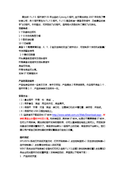
美加狮F.L.Y.5 摇杆源于05年出品的Cyborg X摇杆。
由于美加狮在2007年收购了赛钛客公司,将X摇杆更名为F.L.Y.5摇杆。
F.L.Y.5是目前唯一具备多种调节,功能最全的单手飞行摇杆。
外形酷炫,可拆卸的飞行摇杆。
适用绝大多数的热门模拟飞行游戏。
功能特点:1个快速响应扳机1个8方向视角苦力帽1个鼠标滚轮键10个功能键具备5个高精度模拟轴,X、Y、Z轴及独特的双油门调节设计,可控制多个发动机或副翼/节流阀整合使用1个模式切换键杆头具备前后调节及倾斜调节杆身具备长短调节及倾斜度调节底座可收缩。
杆身与底座可分离。
支持ST可编程技术产品包装及配件:产品包装全球统一全英文文字,有中文标贴,产品提供2年质保服务。
内含摇杆底座1个,摇杆杆身1个,产品安装英文说明书一份。
安装方法:(1)拿出摇杆‘杆身’和‘底座’。
(2)用手拿住‘底座’两边向外拉,底座展开。
(3)将摇杆‘杆身’对准‘底座’接口处,注意接口处的卡槽位置,接好后,并旋紧。
(4)将摇杆的USB口插在电脑上。
(5)登录官网下载驱动和ST软件/Web/Download.aspx,安装前请退出杀毒软件和防火墙。
先安装驱动,再安装ST软件。
如果你不需要编辑ST软件,也可以不用安装。
美加狮的摇杆支持即插即用,你可以直接插在电脑上就可以。
然后到游戏里进行按键设置就行了。
有些游戏会默认一些摇杆上的功能,有些游戏不会默认。
我们建议用户都自己到游戏里的按键设置里进行自定义设置。
摇杆测试:XP\VISTA系统打开测试页面方式:打开开始菜单=〉点击控制面板=〉双击游戏控制器=〉选中控制器=〉点击属性按钮进入测试页面WIN7系统点击开始菜单》设备和打印机》选择F.L.Y.5,右键》游戏控制器设置》点击属性》将会出现如图所示的设置界面(没有装驱动的,界面跟以下略有不同):1.产品测试页面:1)按键测试:依次按下摇杆上的各个按键,摇杆示意图中相应的按键会亮;2)苦力帽测试:将摇杆顶部的苦力帽(POV)向各个方向轻压到底,窗口POV Hat区域中对应的方向箭头应显亮,放开苦力帽,中间“0”号位置的红灯应该显亮;3)轴向的测试:首先测试“俯仰/横滚控制”:当摇杆置中的时候,X轴/Y轴区域中的十字标也应该在中间位置,随着摇杆向前向后、向左向右运动,十字标应平滑的跟随移动,并应当到达测试区域的边框。
基恩士离子风棒说明书
基恩士离子风棒说明书
离子风棒是一种固定式静电消除的专用设备。
属棒式除静电产品的一种。
具有安装简易、工作安全稳定、消除静电速度快的特点。
主要用于电子、塑胶、丝印、印前系统、图像处理等行业。
同时也用在塑料薄膜和纸张印刷的卷覆裁切生产设备中。
风棒长度可根据不同的要求定制,使用于不同的设备。
离子风棒可产生大量的带有正负电荷的气团,可以将经过它离子辐射区内的物体上所带有的电荷中和掉。
当物体表面所带为负电荷时,它会吸引辐射区内的正电荷,当物体表面所带为正电荷时,它会吸引辐射区内的负电荷,从而使物体表面上的静电被中和,达到消除静电的目的。
自拍杆用户手册说明书

e Stick from the list of Bluetooth devices.1. Phone holder2. Angle adjustment3. Selfi e/Power button4. Retractable stick5. Charging port3 245e Stick in de lijst met Bluetooth-apparaten. 1. Telefoonhouder4. Uitschuifbare stick5. Oplaadpoortapparaten.2. Knoppen om de hoek aan te passen3. Selfi e-/ aan-uitknop3245Setze dein Smartphone in die Smartphone-Halterung. ktiviere Bluetooth an deinem Smartphone oder Tablet.e Stick aus der Liste der Bluetooth-Geräte aus. 1. Smartphone-Halterung4. Teleskopstange5. Ladeanschlussung.Tablet.Geräte aus.2. Winkeleinstellung3. Selfi e + Ein-/Aus-TasteDE32415e Stick premendo il pulsante di accensione. e Stick dall’elenco dei dispositivi Bluetooth.e Stick e regolalo in base all’angolazione del 1. Portacellulare4. Bastone retraibile5. Porta per la ricaricansione.etooth.ne del 2. Pulsanti di regolazione dell’angolazione3. Pulsante per i selfi e - Interruttore di alimentazioneIT 32415e Stick antes de utilizarlo.Activa la función Bluetooth en tu smartphone o tableta.e Stick de la lista de dispositivos Bluetooth. 1. 4. Stick retráctil5. Puerto de cargaarlo.ableta.luetooth.Soporte para teléfonos 2. Ajuste de ángulo 3. Botón para selfi es - Botón de encendido y apagadoES 32415Carrega totalmente a bateria antes de utilizares o Selfi e Stick premindo o botão de Ligar/Desligar. e Stick na lista de dispositivos Bluetooth.e Stick e regula o ângulo do suporte para o 1. 4. Monopé telescópico5. Porta de carregamentoSelfi e Stick.ligar.etooth.e para o Suporte para telemóvel2. Botões de regulação do ângulo3. Botão Selfi e - Interruptor de alimentaçãoPT 32415e Stick avant utilisation.Placez votre téléphone dans le support prévu à cet eff ctivez la fonction Bluetooth sur votre smartphone ou e Stick dans la liste des périphériques 1. 4. Perche télescopique5. Port de chargetion.et eff et.ne ou hériques Support de téléphone 2. Boutons de réglage de l’angle 3. Bouton de selfi e - Commutateur marche/arrêtFR 32415。
- 1、下载文档前请自行甄别文档内容的完整性,平台不提供额外的编辑、内容补充、找答案等附加服务。
- 2、"仅部分预览"的文档,不可在线预览部分如存在完整性等问题,可反馈申请退款(可完整预览的文档不适用该条件!)。
- 3、如文档侵犯您的权益,请联系客服反馈,我们会尽快为您处理(人工客服工作时间:9:00-18:30)。
1.概述
FZBJ-1型10米支撑杆是用于自动气象站气象观测仪器安装、气象传感器的专用设备。
于原有风杆相比它具有操作十分方便,风杆的立起和放倒只需一个人即可;风杆的安装和拆卸简便;保证具有足够的抗弯刚度,无需拉线;全部采用热镀锌,保证良好的抗腐蚀性能等优点。
2. 技术指标
2.1 高度:10m
2.2 最大承受风速:不大于70m/s
2.3 重量:约450Kg
3. 安装说明
3.1 地基:
主体杆地基应按照要求进行施工,地脚螺栓M20×800应和施工模板同时浇灌施工,施工时螺栓露出模板100mm,在模板两侧用螺母夹住(见图一、图二)。
地基应具
图一图二
有钢筋笼加强,各地脚螺栓应和钢筋笼焊接在一起,钢筋笼上圈距混凝土地基面约
30mm,钢筋笼选用HRB335直径16的钢筋制作,若施工地点土质较硬基础深度允许
缩短,但不应小于800mm 。
(见图G1.0B)。
浇注混凝土时应注意保证施工模板的水平、各地脚螺栓的竖直,混凝土地基高出地面约150mm(见图G1.0C)。
地基混凝土规格选择C25即可,浇注时可以使用振动棒密实混凝土,所需混凝土体积大约为0.9立方米。
3.2 主体杆的安装架设
3.2.1 将底板焊接件通过螺母固定于施工模板(地基)上。
3.2.2将左右槽钢焊接件按照装配示意图分别安装在底板焊接件两侧(见G1.0A),注意此时不要将螺栓旋紧,所有螺栓均应配有防松垫圈(下同)。
3.2.3将底杆放入左右槽钢焊接件的中间,将底杆上的轴孔和左右槽钢上的轴孔对齐,注意留意底杆走线孔的方位。
对齐后将轴插入轴孔中,在穿轴过程中将两个橡胶垫分别放在底杆轴孔的两侧,被主轴一并穿过。
主轴插至最顶后见主轴卡板卡在主轴的卡槽上,并用螺丝将卡板固定在主体槽钢上(见图三)。
然后将底座上的所有螺栓旋,紧所施加预紧力大致为全身重量,注意对置槽钢上的螺母位于槽钢外侧。
图三
3.2.4将底杆放平,电缆线穿过底杆(电缆线的布置视情况而定,取决于自由端-即可以穿过走线孔的线端。
),将中杆接上(中杆中走线应同时或者提前完成,在中杆
和底杆的上部用6个M10×25的螺钉和弹簧垫圈紧固),可以将底杆略微后翘,将填充物依次塞入。
在塞入第3个填充物之后,可以将顶杆接上(在顶杆和中杆的上部用6个M10×25的螺钉和弹簧垫圈紧固),然后填充其余配重。
(见图四、图五)
图四
图五
3.2.5 将底端前挡板通过螺钉固定于槽钢上,将支撑杆立起,然后安装其余挡板。
(见G1.0A)
3.2.6 将机箱通过表箱连接件固定于主体槽钢两侧。
注:步骤可参阅主体杆安装步骤图解(Z1.0)
4. 维护保养
4.1当检修需要放倒主体杆时应先松开后上挡板和前上挡板的螺丝将其翻开,然后一手顶住主体杆一手慢慢松开后下挡板的螺丝将其翻开,小心的顺势将杆抬起放平成图五状。
检修完成将主体杆底部拉下顺势推入架子中,主体杆到位后翻好后下挡板并将螺丝锁好,最后将后上挡板和前上挡板翻好并锁紧所有螺丝。
(见图六)
图六
4.2应经常检查主体槽钢连接处螺栓和地脚螺栓的紧固性,尤其是经常刮风的季节。
当检修需要放倒主体杆时,应注意避免损坏传感器和杆的油漆表面。
4.3 FZBJ-1型10米支撑杆安装保养时可用到以下工具
14号扳手→M8螺栓,17号→M10螺栓
24号扳手→M16螺栓,30号扳手→M20螺栓
FZBJ-1型10米支撑杆示意图
装配示意图(G1.0A)
装配示意图(G1.0A)
钢筋笼示意图(G1.0B)
混凝土地基示意图(G1.0C)
主体杆安装步骤图解(Z1.0)第一步:安装底板焊接件
第二步:安装左右主体槽钢焊接件
第三步:安装底杆和主轴
第四步:安装中杆和顶杆
注:塞填充物前应先把靠近主轴的填充物定位螺栓装上。
第五步:立起风杆固定挡板,安装表箱及其他配件。
