手持式自动锁螺丝机--思科锐
手持式螺丝枪有哪几种用法

手持式螺丝枪有哪几种用法
手持式螺丝枪是自动锁螺丝机的一种。
设计简单又适合规格不一的产品的半自动锁螺丝机。
我们通常称它为手持式自动锁螺丝机、手提式锁螺丝机等。
主要的构建就是一个吹气式自动螺丝供料器,一个自动排列螺丝卡盘、一把锁螺丝电批。
虽说外观看起来简单小巧,但是实用性却是很高的,像很多过大过小的产品,不适用于平台桌面式锁螺丝机的尺寸的,都可以考虑手持式螺丝枪哦。
当然您考虑到员工长期手动操作这个设备,会不会产生疲劳感?所以我们今天贴心为大家整理出手持式螺丝枪好用的几种方式。
常见形式将电批和供料器的管道固定在支架上,一把电批的重量在500-1000克之间,锁付过程中,只要拿起电批对准锁付孔按下开关按钮可以可完成一个螺丝锁付哦。
自动化简单改造使用,将手持式螺丝枪的电批订制一个龙门支架,产品做好夹具,配置一款脚踏开关代替电批按钮,只需脚踏开关就可以轻松完成螺丝锁付。
这可是我们为大家设计的懒人神器哦。
自动化升级改造,将设备以自动化形式做好流水线加工模式,详情可观看我们手持式自动锁螺丝机视频哦,还有更多精彩自动锁螺丝机视频花絮欢迎您观看。
手持式螺丝枪有哪几种用法自动锁螺丝机手持式自动锁螺丝机手提式锁螺丝机手持式自动锁螺丝机视频自动锁螺丝机视频手持式螺丝枪平台桌面式锁螺丝机。
Cherry G749A 手动焊钉螺纹机说明书

G749A CHERRYMAX ®HAND RIVETERNSN 5120-01-148-5847DESCRIPTIONThe Cherry G 749A is a heavy-duty,hand operatedhydraulic riveter designed specifically for the mostef f ic ient ins ta lla tio n of C he r r yMAX ®.It w eig hs23/4pounds,is 15"long without a pulling head and has a0.518"stroke.Pulling heads are not furnished with this riveter andmust be be ordered separately.H749A-456(straight),H753A-456(right angle)and H781-456(offset)pulling heads fit directlyon the G 749A Riveter.Pulling head extensions are alsoavailable to reach into limited access areas;seeCherryMAX®catalog for part numbers.The G 749A riveter with above listed pulling heads will in-stall Bulbed CherryMAX®rivets in 1/8",5/32"and 3/16"nominal and oversized diameters,in all materials,head stylesand grip lengths.The G 749A riveter with the H749A-456or H753A-456pulling heads will install 1/8",5/32"and 3A 6"Wiredraw CherryMAX®'A'rivets in all head styles and materials up to a -4grip length.Withthe H781-456pulling head it will install 1/8"and 5/32"Wiredraw CherryMAX®'A'rivets in all head styes andmaterials up to a -4grip lengths.To install serrated stem MS-type rivets,use adapter 704A9and a screw-on type serrated stem pulling head of the correctsize.PARTS LIST FOR G749A RIVETERREF.NO.PART NUMBER DESCRIPTION QTY REC 1P307Retaining Ring 12P8820-Ring 23749C11Eng Plug Assembly 1*3A704B2-2Nose Fitting 1*3B749C11-1End Plug 14P8770-Ring 35P9210-Ring 16749C63Drawbolt Piston 17P878Back-up Ring 18755A9Spring 19745A7Pump Bushing 110P7210-Ring 111P572Stat -O-Seal 312745Al2Screw Lock 113P3830-Ring 114745A5Bladder 115P7010-Ring 116745842Vent Plug 117745C51Valve Sleeve Assembly 118P573Button Hd.Cap Screw 219745C3A Housing Subassembly 120745A28Spring Retainer 121745M6Spring 122P977Poppet Valve 123P1110-Ring 124P10070-Ring 225745815Pump Piston 126745A21Link Pin 227P954Link Plate 128P1138Roll Pin 129745C19Pivot Handle 130P1011Handle Grip 2*Use Loctite No.271,or equivalent,when assembling items 3A and 3B,when orderedG749A HAND RIVETERAn assortment of O-rings,seals,screws,washers and gaskets likely to need replacing in time,is available in kit form for each Cherry power riveter.To avoid unnecessarydowntime,it is advisable to have these kits on hand for the tools to be serviced:CHERRY TOOL SERVICE KIT NUMBER G749A G749KSHOW THE G749A OPERATESBy-pass valve button is pressed,permitting a strongspring to push the drawbolt piston to its forward posi-tion.This opens the jaws in the pulling head to acceptthe rivet stem.When pivot handle is "pumped"ATF (Automatic Trans-mission Fluid)is forced into the front of the housingcylinder.The pressure of the ATF fluid pushes thedrawbolt piston back in a full .518"setting stroke.At the end of the setting stroke,a pressure relief valve is opened allowing ATF fluid to move within the hydrau-lic system preventing a hydraulic locked condition and possible damage to the tool.When the rivet is set,a touch of the by-pass valve button releases the hydraulic pressure,permitting the spring to return the drawbolt piston to its starting position,ready to install the next rivet.Tilt nose of tooldown to permit spent stem to drop out.G749A HAND RIVETEROPERATION1.Press by-pass valve button.2.Insert rivet stem into nosepiece.3.Insert rivet into work with riveter nosepieceheld firmly against head of rivet.4.Pump pivot handle to set rivet.It may benecessary to repeat cycle if rivet is extra long.5.When rivet is set,press the by-pass valvebutton to release hydraulic pressure.Tilt nose of tool down to permit spent stem to drop out.HOW TO FILL RIVETER WITH FLUIDAir Bleeder745A45should be used for proper refilling Fill unit transmission fluid type ATF220or equivalent1.Remove two cap screws and Stat-O-Seals fromports A(rear)and B(front opposite side).2.Attach745A45air bleed hose to port A(rear)andforce fluid into tool.Fluid(and probably air bubbles will come out of port B.When there are no more bubbles,replace cap screw and Stat-O-Seal in portB.Do not disconnect745A45air bleeder fromport A.3.Remove cap screw and Stat-O-Seal from port C(other front screw).With745A45air bleeder,force fluid into port A and out of port C,while at the same time actuating pump handle.When there are no more bubbles,replace screw and Stat-O-Seal in port C.4.With both ports B and C now closed,force a littlemore fluid into tool to partially collapse reservoir bladder.Remove bleeder and quickly replace screw and Stat-O-Seal,retaining as much fluid as possible in tool.5.If tool does not pull properly after cycling pumphandle several times,repeat all steps.Note:In forcing fluid into tool,be careful to prevent air from entering.Be sure bleeder hose fitting is tightened sufficiently in port A before proceeding.MAINTENANCE AND REPAIRThe G749A Hand Riveter has been manufactured to give maximum service with minimum care.Virtually all of the moving parts in this tool ride on O-rings,pro-tected by backup rings where high pressure dictates. This means no metal to metal wear.By use of close tolerances and low micro-inch surfaces against which the O-rings seal,a long service life can be expected before any overhaul becomes necessary.In order to enhance the service life of the G-749A,the following recommendations should be followed:1.The hydraulic system should be full and free fromair at all times.2.Do not pound on the rear of the tool head to forcerivets into holes as this will damage the tool.3.Make sure the puling head is correctly and securelyattached.TROUBLESHOOTING1.Drawbolt piston does not move when pivot handle is pumped.A.Drawbolt piston is at end of stroke.Press by-pass valve button.B.Air in hydraulic system.(See oil fillinginstructions.)C.O-rings in pump and drawbolt piston are worn.(See disassembly instructions.)2.Hydraulic fluid leads from tool.A.If ATF fluid is leaking around cap screws,tightenscrews.If after cap screws have been tightened,leaks persist,replace Stat-O-Seal washers.B.If fluid leaks from handle grip,the bladder mustbe replaced.(See disassembly instructions.)C.If fluid leaks from pump bushing,O-rings inpump piston are worn and must be replaced.(See disassembly instructions.)D.If fluid leaks from end plug,the O-rings on draw-(bolt piston and in end plug are worn and mustbe replaced.(See disassembly instructions.)3.Pulling head does not grip rivet stem.If pulling head does not grip rivet stem,disassem-ble and clean pulling head components.Replace worn or damaged parts as required.Install per in-structions on page8.4.Pulling head does not release stem.A.Drawbolt piston is not fully forward.Press by-pass valve button.B.Pulling head is not properly installed on tool.Install per instructions found on page8.C.Pulling head needs cleaning.Disassemble,clean and replace worn or damaged parts andinstall per instructions on page8.OVERHAULWARNING:Do not disassemble tool before reading instructions thoroughly.Injury could result from heavy spring pressure on drawbolt piston and end plug.Approved eye protection should be worn.NOTE:749C64Assembly/Disassembly tool is recommended for any repair on the G749A riveter.It should never be necessary to dismantle this rivet tool completely.However,if it develops a problem in one of the areas mentioned under Trouble Shooting, the tool may be disassembled by section utilizing the following instructions and the drawings on pages4 and5.Before doing any disassembly—remove screws(31) and Stat-O-Seals(17).Drain transmission fluid from the riveter.During disassembly use care not to mar, nick or burr any smooth surface that comes in con-tact with O-rings.1.Pivot Handle&Pump PistonCarefully press out roll pin(41)in order to remove pump piston(38)and pivot handle(42)subassembly from housing(32).Drive out link pins(39)to remove link plate(40)from pump piston(38)and pivot handle(42).Items34,35,36and37can be removed from pump piston(38)once spring retainer(33)is removed.Han-dle grip(43)slips off handle(42)if replacement is necessary.To reassemble,reverse above procedure,being cer-tain that all O-rings are lubricated with a good rubber lubricant.Install roll pin(41)as shown on page5.To refill tool with ATF fluid,see refilling instructions for proper procedure.2.By-pass Valve AssemblyRemove by-pass valve assembly(19-26)from housing(19)and check parts and O-rings for wear or damage and replace as necessary.To remove valve actuator(26),first loosen valve sleeve (23)and remove from housing(32).Remove screw(19) to remove items20,21and26.Remove O-ring(22) from sleeve(23)and O-ring(25)from actuator(26).Be sure to apply good rubber lubricant to all O-rings prior to reassembling.It is advised that No.222Loc-tite be applied to ball seat(31)and set screw(36) threaded components when reassembling.Allow24 hour curing time for loctited components before assembling by-pass valve assembly(745651)into housing(19).3A.End Plug and Drawbolt Piston Assembly without Disassembly Tool749C63Remove pivot handle,pump piston and by-pass valve assemblies from tool.Remove pulling head internal components from tool and replace pulling head sleeve, with nosepiece removed,back in nose fitting(3). Place a spacer block(7/16"x11/8"x1/8")in position where pivot handle was mounted.This will help stabilize tool during compression of spring(14). Remove screw lock(18)and Stat-O-Seal(17).Place tool and spacer block in a press with a12"minimum opening capacity.Press pulling head sleeve and end plug(3A)into tool enough to relieve pressure or to allow removal of retaining ring(1)and allow its removal. WARNING:Spring(14)is compressed under very heavy pressure.Remove with care!Approved eye protection should be worn.Carefully raise press anvil allowing pulling head sleeve, end plug and drawbolt piston.Assembly(2-14)will be forced from tool by60pounds pressure applied by spring(14).Remove tool from press and remove pull-ing head sleeve from nose fitting(3).Remove end plug(3A)from drawbolt piston assembly (5-13).Remove drawbolt piston assembly from hous-ing.Remove O-ring(5)and retaining ring(6)in order to remove spring(8)and valve stem(9).Remove re-taining ring(13)in order to disassemble springs(8), valve actuating washer(11)and spring seat(12). Remove O-ring(4)and back-up ring(10).Spring(14) is also removed from housing at this time. Carefully inspect all the components1through15for wear or damage and replace as required.To reassemble reverse above procedure being sure all O-rings are coated with a good rubber lubricant.3B.End Plug and Drawbolt Piston Assembly. Disassembly Instructions Using Disassembly Tool 749C64.Prior to any disassembly...remove screws(18)and Stat-O-Seals(11).Drain transmission Fluid from the riveter. During disassembly,use care not to mar,nick or burr any smooth surface that comes in contact with O-rings. Attach749B68cap to nose fitting(3).Slide disassem-bly tool over riveter housing.Attach tool to riveter by installing hex soc.cap screw(P-1200)thru roll pin(28) and securing with wing nut(P-1199).Turn toggle screw (P-1201)through crossbar(745B67)until it tightens into cap749B68.Turn toggle screw with3/16"hex key (P-1187)clockwise until pressure has been relieved on retaining ring(1)allowing its removal. WARNING:Spring(8)is compressed under very heavy pressure.Remove with care!Ap-proved eye protection should be worn. Remove screw lock(12)and Stat-O-Seal(11).Carefully turn3/16hex key(P-1187)counter-clockwise allowing end plug and drawbolt piston assembly(2-7)to be forced from tool by60pounds spring(8)pressure. Remove disassembly tool from riveter.Remove end plug(3A)from drawbolt piston assembly (4-7).Remove drawbolt piston from housing.Remove O-ring(5).Remove O-ring(4)and back-up ring(7). Spring(8)is also removed from housing at this time. Carefully inspect all parts(1thru10)for wear or damage and replace as required.To reassemble re-verse above procedure being sure all O-rings are coated with a good rubber lubricant.4.Bladder AssemblyRemove handle grip(43)on stationary handle. Remove retaining ring(30).Thread on8-32bolt into vent plub(29)and extract bladder assembly.Check components27through30for damage and replace as necessary.To reassemble,reverse procedure being sure all O-rings are coated with a good rubber lubricant.。
CO-SHARE智能无刷电批特性简介
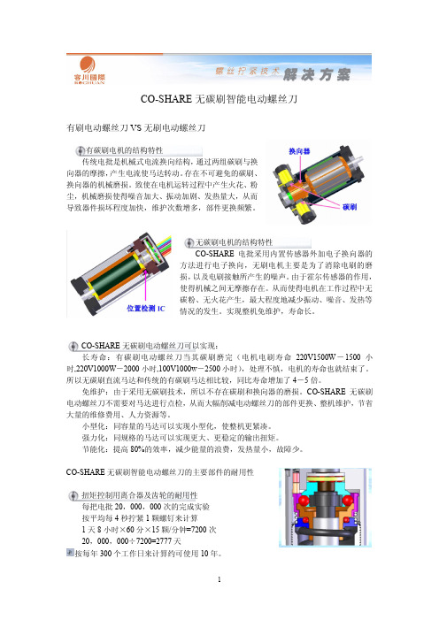
CO-SHARE无碳刷智能电动螺丝刀有刷电动螺丝刀VS无刷电动螺丝刀有碳刷电机的结构特性传统电批是机械式电流换向结构,通过两组碳刷与换向器的摩擦,产生电流使马达转动。
存在不可避免的碳刷、换向器的机械磨损。
致使在电机运转过程中产生火花、粉尘,机械磨损使得噪音加大、振动加剧、发热量大,从而导致器件损坏程度加快,维护次数增多,部件更换频繁。
无碳刷电机的结构特性CO-SHARE电批采用内置传感器外加电子换向器的方法进行电子换向,无刷电机主要是为了消除电刷的磨损,以及电刷接触所产生的噪声。
由于霍尔传感器的作用,使得机械之间无摩擦存在。
从而使得电机在工作过程中无碳粉、无火花产生,最大程度地减少振动、噪音、发热等情况的发生。
实现整机免维护,寿命长。
CO-SHARE无碳刷电动螺丝刀可以实现:长寿命:有碳刷电动螺丝刀当其碳刷磨完(电机电刷寿命220V1500W-1500小时,220V1000W-2000小时,100V1000w-2500小时),处理不慎,电机的寿命也就结束了。
所以无碳刷直流马达和传统的有碳刷马达相比较,同比寿命增加了4-5倍。
免维护:由于采用无碳刷技术,所以不存在碳刷和换向器的磨损。
CO-SHARE无碳刷电动螺丝刀不需要对马达进行点检,从而大幅削减电动螺丝刀的部件更换、整机维护,节省大量的维修费用、人力资源等。
小型化:同容量的马达可以实现小型化,使整机更紧凑。
强力化:同规格的马达可以实现更大、更稳定的输出扭矩。
节能化:提高80%的效率,减少能量的浪费,发热量小,故障少。
CO-SHARE无碳刷智能电动螺丝刀的主要部件的耐用性扭矩控制用离合器及齿轮的耐用性每把电批20,000,000次的完成实验按平均每4秒拧紧1颗螺钉来计算1天8小时×60分×15颗/分钟=7200次20,000,000÷7200=2777天按每年300个工作日来计算约可使用10年。
轴承的耐用性(CO-SHARE无碳刷智能电动螺丝刀采用的是日本NMB-美培亚、日本NSK-精工的轴承)轴承制造厂商的品质保证为40,000小时假设每天需拧紧7200颗螺钉,实际使用时间为4小时(1颗/2秒)40,000小时÷4小时=10,000天10,000天÷300天工作日=33年按国内厂家两班倒制度计算约可使用10年霍尔感应开关(霍尔感应开关功能说明及与传统的微动开关比较说明)传统微动开关微动开关,内部有机械触点影响寿命因素:触点的寿命及机械寿命日本“日开”的寿命保证为100万次大陆国产的寿命为10万次霍尔感应开关CO-SHARE电批采用的霍尔感应开关为非接触型,不存在磨损,因而不存在使用次数的限制,其寿命和其它半导体器件相似,为半永久型,和传统的触点开关比较,其寿命有了等级性的提高,使用寿命约为2000万次。
sc5000

OP5000 No Yes In32bit/Out32bit ×3(max)
In32Bit/Out32bit ×1
TP5000 or OP5000
AD1346
In16Bit/Out8bit ×1
关于上述产品的咨询,请咨询我公司营业部。 日电产三协电子(深圳)有限公司 广东省深圳市福田中心区益田路4068号卓越时代广场1005-1008室 TEL: (86)755-8359-2335 FAX: (86)755-8359-3532 日电产三协电子(上海)有限公司 上海市漕溪北路18号実業大厦28楼B.C. TEL: (86) 21-6427-2460 FAX: (86) 21-6427-2458 日本电产三协(香港)有限公司 香港新界葵芳兴芳路223号新都会广场第二座26楼2605-2606室 TEL: (852) 2369-6855 FAX: (852) 2724-2702
机器人控制器
■SC5000
■特点 z多程序的控制…可以同时控制多台机器人,周边装置。 z机器人控制…考虑到实用的扩张性・便利性支持多动 作的操作,编程的操作性,动作确认等简易化 z配备GUI液晶…带操作面板彩色液晶表示,高直观感 的识别性实现快捷的操作 异常诊断机能,预防保全机能,多语言信息的装备
■性能
SC5000-UHP Specifications Dimensions (W)×(H)×(D) (mm) Weight Power supply Rated drive Instantaneous max. output Drive servo motor Servo Type of motor servo Servo axes Programming language Interface Serial Communication Ethernet Parallel I/O Remote I/O AnyBus 1 slot (Optional) Safety I/O Safety I/O Option Teaching Pendant Remote SW Box Stepping Motor 制御 Parallel I/O (Additional) Standard Safety Standard
CVI3拧紧控制器安装和升级手册说明书

硬件安装 .............................................................................. 10 安装控制器、工具和配件............................................................ 10 技术数据 ................................................................... 10 建议安装顺序 ............................................................... 13 安装控制器 ................................................................. 13 连接线缆工具 ............................................................... 26 将无线缆工具连接到 CVI3 Vision ............................................. 28 安装eBUS配件 ............................................................... 32 安装ePOD ................................................................... 43 安装现场总线模块 ........................................................... 44 安装外围设备 ............................................................... 44 将控制器连接到电源 ......................................................... 45 打开/关闭控制器电源 ........................................................ 46 如何设置网路 ............................................................... 47 如何将 CVI3 控制器连接到计算机 ............................................. 49 安装连接到以太网的完整解决方案 ............................................. 49
西门子 NXGPro+ 控制系统手册_操作手册说明书

3.4
单元通讯的协议 ............................................................................................................ 36
3.5
NXGpro+ 高级安全 .......................................................................................................37
3.2
功率拓扑 ......................................................................................................................34
3.3
控制系统概述 ...............................................................................................................35
NXGPro+ 控制系统手册
NXGPro+ 控制系统手册
操作手册
AC
A5E50491925J
安全性信息
1
安全注意事项
2
控制系统简介
3
NXGPro+ 控制系统简介
4
硬件用户界面说明
5
参数配置/地址
6
运行控制系统
7
高级的操作功能
8
软件用户界面
9
运行软件
10
故障和报警检修
11
手持电动螺丝刀使用说明书
手持电动螺丝刀使用说明书使用说明书尊敬的用户:感谢您购买我们的手持电动螺丝刀。
为了您更好地使用和了解该产品,请仔细阅读本使用说明书。
1. 产品介绍手持电动螺丝刀是一款便携式工具,适用于家庭和专业使用。
它采用先进的电动技术,可快速拧紧和拆卸各种螺丝。
2. 使用安全须知为了确保您和他人的安全,请务必遵守以下安全须知:a) 在使用前,请仔细阅读用户手册,并按照说明操作。
b) 在使用过程中,请戴上适当的防护眼镜和手套,以防眼睛和手部受伤。
c) 当您长时间使用螺丝刀时,请注意适当的休息,避免过度劳累。
d) 在使用或存放螺丝刀时,请远离易燃物品和湿润的场所。
e) 请确保螺丝刀无法触及到电线或其他导体,以避免电击危险。
3. 产品组装与操作a) 组件包括手持电动螺丝刀本体、螺丝刀头和电源适配器。
b) 在首次使用前,请确保电源适配器已连接好,并通过指示灯显示电源状态。
c) 选择适当的螺丝刀头,将其插入螺丝刀头接口,并旋转固定。
d) 按下开关按钮启动螺丝刀。
请注意,按下按钮时,刀头会旋转。
请小心避免手指接触到刀头。
e) 当不再需要使用螺丝刀时,请将其关闭,并拔掉电源适配器。
4. 拧紧与拆卸螺丝a) 在拧紧螺丝时,将螺丝刀头对准螺丝孔,并轻轻按下刀头。
启动螺丝刀,直到螺丝紧固,然后放开开关按钮。
b) 在拆卸螺丝时,将螺丝刀头对准螺丝孔,并按下刀头,使其反转。
启动螺丝刀,直到螺丝松动,然后放开开关按钮。
5. 电池充电与更换a) 当螺丝刀使用效果降低时,请将电源适配器连接到电源插座,并将螺丝刀插入充电插座。
充电指示灯将亮起。
b) 充电时间约为2小时。
充电完毕后,断开电源适配器,以避免过度充电。
c) 当电池无法再正常使用时,请将其取出,并更换为新的适配电池。
请确保选择适配电池,以避免不良后果。
6. 清洁与维护a) 在清洁螺丝刀之前,请先断开电源,并拔下电源适配器。
b) 使用干净的布擦拭螺丝刀表面,以去除尘土和污垢。
c) 定期检查刀头是否磨损或损坏。
螺丝机机械手臂使用说明书

螺丝机机械手臂使用说明书一、产品简介螺丝机机械手臂是一种先进的自动化设备,广泛应用于工厂生产线的自动化装配过程中。
该设备具有高效、精度高、稳定性好等特点,能够大幅提升生产效率和产品质量。
本使用说明书将详细介绍螺丝机机械手臂的使用方法和注意事项。
二、安装与调试1. 安装将螺丝机机械手臂放置在平整稳固的工作台上,连接电源线。
2. 调试a. 打开螺丝机机械手臂控制系统电源,并确保系统正常启动。
b. 根据实际需求,调整机械手臂的工作范围和速度。
c. 使用示教器对机械手臂进行示教操作,将其轨迹和动作记录下来。
d. 完成示教后,进行程序解释执行,确保机械手臂的运动轨迹准确无误。
三、操作方法1. 电源开关操作人员在使用机械手臂之前,需要先打开电源开关,并确保设备处于正常工作状态。
2. 参数设置根据实际需要,配置机械手臂的运动参数,如速度、加速度等。
3. 示教操作a. 使用示教器对机械手臂进行示教操作,并将其动作和轨迹记录下来。
b. 使用示教器的操作按钮,控制机械手臂的动作,如上升、下降、前进、后退等。
4. 运行程序根据实际需求,选择合适的程序进行执行。
操作人员可以在控制台上输入程序编号,并按下启动按钮,机械手臂将按照程序执行相应的动作。
四、注意事项1. 安全操作在使用机械手臂时,必须遵守相关操作规定,确保操作人员和设备的安全。
2. 禁止触碰在机械手臂运行过程中,禁止任何人员触碰机械手臂,并保持一定的安全距离。
3. 维护保养定期对机械手臂进行维护保养,保持设备的良好工作状态,并及时更换磨损部件。
4. 故障排除在机械手臂出现故障时,应及时通知专业技术人员进行排除,禁止非专业人员进行维修。
5. 禁止修改程序禁止未经许可擅自修改机械手臂的程序,以免导致设备无法正常运行。
五、常见问题解答1. 机械手臂无法启动怎么办?请检查电源是否接通,并确保电源线连接牢固;检查控制系统是否正常启动。
2. 机械手臂无法运动怎么办?请检查机械手臂是否处于故障状态,并确保程序选择正确。
自动锁螺丝机操作规程
自动锁螺丝机的操作规程一、自动锁螺丝机操作规程1.开启电源,接通气源,调节好扭力和气压;2.将螺丝倒入螺丝料仓内,螺丝量以不超过螺丝输送轨道高度为宜;3.检查拨码开关是否对应产品型号;4.第一次锁螺丝前,需检查电批夹嘴内是否有一粒螺丝待锁;5.如无一粒螺丝在电批夹嘴上待锁,需按测试按钮,使机器运动两次,保证电批夹嘴上有一粒螺丝在电批夹嘴上等待锁;6.检查供料机振动器调整开关是否在指定的位置上;7.检查完毕,按复位开关,开始生产。
二、自动锁螺丝机操作规定使用设备安全最重要,操作先进自动化设备没有没有规范和管理,且不能发挥它带来的效益,自动锁螺丝机也是一种,虽然自动拧螺丝机安全系数没那么严禁,但正常使用发挥其基本功能,更多的节省时间,提高生产效率,所以对自动拧螺丝机使用及维修管理说明还是有必要知道的。
1.严格执行以岗位责任制、安全操作规程、常规检查、维修保养等安全使用和运营的管理制度。
2.使用操作人员必须经过相应的安全技术培训。
3.制定自动拧螺丝机安全技术性能定期检验制度,根据自动拧螺丝机的安全性能和技术参数,对自动拧螺丝机定期检验,确保自动拧螺丝机运行过程的安全4.自动拧螺丝机的使用人员,负责自动锁螺丝机的日常检查和保养,并做好日常的检查保养记录。
5.针对自动锁螺丝机的使用性质制定交接班制度。
分班轮换使用或集体使用的自动拧螺丝机,由当班负责人全面负责,专人使用的自动拧螺丝机由使用者全面负责自动拧螺丝机的使用安全。
6.大型精密气动工具要严格实行定人、定机的管理办法。
7.对特种自动锁螺丝机严格按照国家有关规定,实行持证上岗。
8.特种自动锁螺丝机必须经过有关部门的培训,经考核合格后方可使用操作。
9.自动锁螺丝机必须严格按照使用说明和安装技术规程的要求进行安装、调试后使用。
螺丝机1控制器-手持版说明书V6.4

双丫轴智能螺丝机控制系统QZ-LS03 (手持盒版)V6.4说明书东莞市领航自动化有限公司目录1. 产品介绍••........................................................................................................................................... (3)1.1产品概述…•… ................................................................................................................................. .31.2功能简介.…… .................................................................................................................................. .31.3功能特性……............................................................. ..31.4产品列表……............................................................. .42. 接线说明图 (5)2.1控制器接线引脚定义... .................................................... .52.2控制器接线说明…… .. ................................................................ .62.3系统连接示意图……. .................................................... .72.4转接板接线说明…................................................................................................... .82.5转接板接线示意图....................................................... . .... .92.6安装尺寸..... .. (10)3. 按键说明 (11)3.1手持盒按键图..... . .................................................... (11)3.2手持盒按键说明........ .................................................... (11)4. 手持盒操作说明 (13)4.1开机画面介绍 (13)4.2主菜单功能介绍.. (15)4.3新增功能操作...... .................................................... .194.4插入指令操作...... .... ................................................ .204.5删除指令操作...... .................................................... .204.6复制指令操作....... .................................................... .204.7阵列复制操作...... .................................................... .214.8偏移操作.. .............................................................. .214.9 批量修改 . .............................................................. .224.10系统....... ... . (22)4.11执行方式操作 (24)4.12复位方式操作 ..... .................................................... .244.13产量设定.............................................................. .254.14取料参数.............................................................. .254.15配置选项.............................................................. .264.16空移速度.............................................................. .264.17对针操作.............................................................. .265. 注意事项... . (27)5.1 装机事项 . .............................................................. .275.2常见问题说明与故障排除... ................................................ .271.产品介绍1.1产品概述QZ-LS03是由本公司专业数控团队为螺丝机行业量身定做的低成本、高浓缩、高集成度的智能螺丝机控制系统。
手持式终端 AK-W402L 使用说明书

2 本機特點3 各部名稱4 安裝方法5 功能操作6 CD唱片的使用 6 CD唱片的播放6 搜尋特定樂曲7 重覆播放7 程序播放記憶 7 檢查程序記憶 8 增加程序播放記憶 8 變更程序播放記憶8 清除程序播放記憶9 耳機的使用10 保養方法11 故障排除12 緊急處理方法13 關於售後服務1.CD門2.CD LCD 顯示幕3.CD PLAY (CD播放鍵及暫停鍵)4.BACK (CD反向選曲及跳曲鍵)5.REPEAT(CD重覆鍵)6.BAND DIAL POINTER(波段頻率指示)7.TUNING(調諧鈕)8.NEXT (CD順向選曲及跳曲鍵)9.PROG(CD程序編輯鍵)10.STOP(CD停止鍵)11. VOLUME(音量調整鈕)12.FUNCTION(功能選擇鍵)13.天線14.電源線(在電池盒內)15.耳機孔包裝清單: 手提式CD音響1台 附件: 電源線1條 使用說明書1本 保證書1份5613247151314收音機:將 FUNCTION (功能選擇鍵)推至AM調幅(收音機)狀態收聽電台廣播。
將 FUNCTION (功能選擇鍵)推至FM調頻(收音機)狀態收聽電台廣播。
CD唱片:將 FUNCTION 推至CD功能,按下CD PLAY (CD播放及暫停鍵)時,如果裝有CD唱片即進入CD播放功能。
旋轉 VOLUME ,可依個人需要調整音量的大、小聲。
交流供電:當插上交流電源插頭後本機已經接通電源,如若不想消耗電源,確保安全,電源請在不使用時拔掉電源插頭。
電池供電:打開機底電池蓋,照指示依正負方向放入6個2號電池。
在使用電池時,請將機後插上的交流電源線插頭拔出,如未拔除電源線插頭,電池將無法供電。
本機應安裝於陰涼、乾燥、通風、無腐蝕性氣體的地方。
盡量避免放在潮濕或高溫曝曬的地方。
利用 FUNCTION 來選擇調頻FM或調幅AM接收電台廣播。
旋轉 TUNING (調諧鈕)來選擇所需要聽的電台頻率位置。
爱默生_EV1000系列变频器说明书【实用精品】

第三章 安装及配线............................................................10 3.1 变频器安装..........................................................10
3.1.1 3.1.2 3.1.3 3.1.4 3.1.5 3.1.6
变频器运行命令通道 ..................................24 变频器频率给定通道 ..................................24 变频器工作状态 ..........................................24 变频器运行方式 ..........................................24
Cherry G800 手力瞬间紧固器说明书

STROKE PULLING FORCE (adjustable)POWER SOURCEWEIGHT (WITHOUT)PULLING HEAD) 3/4" min.Up to 6000 lbs. Hand Pump1.7 lbs.The Cherry ® G800 is an ergonomic, lightweight hand powered riveter capable of installing a wide variety of blind type fasteners.The all metal design makes this compact and robust tool ideal for use in rugged repair facilities and field repair. The exceptional power multiplication provides up to 6000 Lbs.FEATURES & BENEFITSergonomic designLightweight with cushioned handle and adjustable lever span An internal shock absorber reduces operating shocksSmart power optimization system provides extremely high loads at low hand effort and increased productivityversatileCherryMax® mounting system (same as G704B) compatiblewith our most popular pulling heads like H782, H781-456, H753A-456A full line of slim pulling heads available for a wide variety of blind fastenersreliableThis product was subjected to extensive testing; its quality is backed by the Cherry® reputation for high quality tools.Your Cherry® tools remain the industry leader in after sales support.economicalIt is built to last and to require minimum service. It features: High strength steel and aluminum constructionLeak proof design with advanced seals and built-in redundanciesDurable coatings for use in harsh environmentssimple, cost-effective maintenanceSafe & quick access to wear items (jaws, jaw follower)Visual fluid level indicator and easy to follow troubleshooting guideService, repair, refill in just minutes; no special tools neededTECHNICAL SPECIFICATIONSKIT OPTIONS•G800CMR – This battle damage repair kit includes the G800 riveter equipped with H800, acompact offset (H782), a right angle (H753A-456) pulling heads as well as 886-003 and 782-5BB nose pieces. Additionally, this kit includes a fastener reference guide, grip gauge, andtool documentation (tool manual, tool sheets)•ON-DEMAND KITS- Other kits may be made available at request; please call CHERRY® to discuss your needs.G800KS – service kit: it includes all seals, screws, foam handle, ball bearings and springs.PULLING HEAD SELECTIONYour hand riveter comes with H800 & 782-456; additional nose pieces and pulling heads may be purchased as needed.For Rivetless Nut Plate (RNP) installation, H704-()NP (metallic structure) or H704-()NPC (composite structure); see our tool sheets for more information. For installing other fasteners or RNP removal, call Cherry®; we will be happy to recommend the right configuration. Notes: Items in red, marked with an asterisk (*) are standard components provided with the pulling heads.MODEL NUMBERJAW P/NJAW FOLLOWERNOSE PIECE INSTALLS THE FOLLOWING PRODUCTSCherryMAX, CherryMAX AB: -4, -5, -6 (except 6 Alum)Blindbolt “S” type: -04 & -05MBC Lock Creator: -4, -5, -6NAS1900 "U" type: -4 & -5886-003CherryLOCK “A” Code: -3886-004CherryLOCK “A” Code: -4H800886-005CherryLOCK “A” Code: -5782-010886-002886-006CherryLOCK "A" Code: -6782-5BBBlindbolt “U” Type: -05 782-4MBC Standard MBC: -4782-5MBCStandard MBC: -5782-6MBC Standard MBC: -6782 -6AL CherryMAX "AB" -6 Alum, NAS1900 -4, -5, -6782-33/32” SPR & -3 pull thru NP Rivets RIGHT ANGLE: H753A-456782-4NAS NAS1900, -4 (no shift washer)INSTALLS NAS1400 & 1722 RIVETS782-5NAS NAS1900, -5 (no shift washer)UP TO -04 GRIP782-010886-002782-6NASNAS1900, -6 (no shift washer)*701B18*753A14A*782-456*701B18*753A14A *701B18*753A14A782-010886-002MODEL NUMBER JAW P/N NOSE PIECE INSTALLS THE FOLLOWING PRODUCTSCherryMAX & CherryMAX AB: -4, -5 & -6 (except -6 Alum)Blindbolt “S” type: -04 & -05MBC Lock Creator: -4, -5, -6 NAS1900 "U" type: -4 & -5886-003CherryLOCK “A” Code: -3886-004CherryLOCK “A” Code: -4886-005CherryLOCK “A” Code: -5782-010886-006CherryLOCK "A" Code: -6782-5BB Blindbolt “U” Type: -05 782-4MBC Standard MBC: -4782-5MBC Standard MBC: -5Offset: H782782-6MBC Standard MBC: -6782 -6AL CherryMAX "AB" -6 Al; NAS1900 -4, -5 & -6782-33/32” SPR & -3 pull thru NP Rivets 782-4NAS NAS1900, -4 (no shift washer)782-5NAS NAS1900, -5 (no shift washer)782-010782-6NASNAS1900, -6 (no shift washer)*782-456*701B18*701B18*701B18782-010MODEL NUMBERJAW P/N NOSE PIECE P/NINSTALLS THE FOLLOWING PRODUCTS *652-024CherryMax, "A" Code, "AB" -8 (all materials)652-065Maxibolt Plus -5, 6, 8652-035Maxibolt -8 "S" type 652-065Maxibolt -8 "U" type 652-038Maxibolt -6 "S" type 652-067Maxibolt -6 "U" type744C76865C25*652-043HEAVY DUTY: HD800-8。
手持式自动螺丝机使用说明书

手持式自动螺丝机使用说明书版本A01设备简介操作说明及维护设备保养123锁附结构介绍电批电批气缸上进气口气缸固套进气管电控箱料盒爪片上端分料器导轨后端盘齿轮的细碎粉末。
当长时间不用机器时夹头部位要打上防锈润滑油装螺丝与更换螺丝振动调节振动调节旋钮顺时针钮动振动由小变大,反之由大变小振动过小会引起供料速度不够或停顿,振动过大会引起螺丝叠帽卡住、噪音过大甚至螺丝回流、当出现导轨后端螺丝停滞不前甚至回流状况时,需检查外壳、振动器、轨道螺丝是否有松动,且排除轨道、振动器是否被螺丝或杂料卡住然后清干净供压条前高保证螺丝顺利进入压条,且尽量不叠帽轨道与分料器的间隙1-2MM 之间,小螺丝1MM,大螺丝2MM 轨道向后推时轨道高度要高于分料器导轨0.1mm 以下,槽要中心对齐只要通电振动器会一直振动,如发现开机不振,需拆开此护板清除里面杂料此部位易堆积杂物影响振动,需及时发现清理注意:轨道、振动器被任何东西卡住或憋住都会影响到振动送料,每轨道感应器调节开机状态松开此两螺丝调整感应器上轨道感应器是金属感应器,在其下方以内有金属灯就会亮此两颗螺丝松开后可调整扫把高度,调整时让扫把与轨道平行,恰好能扫掉歪的螺丝,又不碰到轨道和掉入轨道槽的螺丝报警灯轨道中前端当报警灯持续亮灯且蜂鸣时表示缺料、轨道中前段卡料、轨道感应器故障、转盘卡料或转盘上料电机故障排除故障 首先检查料盒里面是否够料(缺料就点菜单按钮会进入设定口令窗口,输入密码:2019确认后进入设置页面窗口来更改参数或进行手工控制(分料清除和更换起子)电批气缸在复位状态时不方便更换起子,按此按钮再按开后电批气缸将夹头顶到气缸另一侧,方便旋转更换起子当分料器卡料导致送料块无法复位时按此按钮,再按开,送料块会拉向气缸一侧,便于清除卡在分料器杂料各动作的时间设定当计数需要清零时按此按钮当系统锁住(锁完螺丝松开开关或手工上料不进行自动上料时),在工作状态会提示要系统解锁时按此按钮输入解锁密码。
HIOS 电动螺丝刀 使用说明书
HIOS电动螺丝刀使用说明书CL系列系列构成CL-2000小系列CL-3000小系列CL-4000小系列CL-6500、CL-6500PS小系列CL-7000、CL-7000PS小系列使用电压DC(直流)30V以下(2020年8月現在)制造商株式会社HIOS总公司邮编131-0045东京都墨田区押上1-35-1TEL:81-3-6661-8821 FAX:81-3-6661-8828NO.ET-A020 20A●为了使您掌握所选机种的使用方法及安全操作,请务必阅读随机附上的使用说明书,正确使用本产品。
●本安全操作注意规程属于一般安全性方面的说明书。
为安全使用请仔细阅读有关内容。
●请绝对不要在指定用途以外使用电动螺丝刀及变压器。
有关作业现场的注意事项 ●要时常整理、整顿作业现场的周围。
保持便于操作的生产作业环境。
●电动螺丝刀等电动工具要避免阳光直射。
●所使用的电压必须符合使用说明书所指定的电压额定值。
如果使用指定以外的电压的话机体将会发生故障诱发触电事故。
●进行生产作业时,聊天会使精神分散,集中力欠佳,是容易致伤引发事故的主要原因。
因此在生产作业时请集中精神进行安全操作。
!注意 ! 警告1.变压器使用HIOS 直流电动螺丝刀,必须有专用变压器。
专用变压器从AC 插座直接获取电力,转换成低压电(各机种有所不同,HI 约为30V ,LOW 约为20V ),供给DC 螺丝刀。
推荐使用CLT-45,CLT-60变压器。
使其具有安全性能高,旋转噪音小等特点。
2.为安全使用●为了能安全使用本产品、请必须按照下面注意事项及警告使用产品。
●请不要以使用说明书指定以外的目的使用电动螺丝刀或变压器。
是引起故障或事故的原因。
●更换碳刷时,由于磨掉的碳粉致使绝缘效果降低,故请交给厂家或经销商进行维护检查。
一般每使用100万次或者每使用1年要做一次检查●请绝对避免与指定电压以外的电源进行连接。
万一发生触电事故或受伤等、本公司不承担责任。
螺丝机的实习报告

一、实习背景随着科技的不断发展,自动化设备在制造业中的应用越来越广泛。
螺丝机作为自动化设备的一种,其生产效率高、精度高、稳定性好等特点,在螺丝制造行业得到了广泛应用。
为了更好地了解螺丝机的生产过程和操作技巧,提高自己的实际操作能力,我在某螺丝机生产厂家进行了为期一个月的实习。
二、实习目的1. 了解螺丝机的生产原理、结构及工作流程;2. 掌握螺丝机的操作方法和技巧;3. 熟悉螺丝机的维护保养知识;4. 培养团队协作精神和沟通能力。
三、实习内容1. 螺丝机的生产原理及结构在实习过程中,我了解到螺丝机的生产原理是利用电机驱动,通过传动系统将电机的动力传递到工作台,使工作台上的螺丝母和螺丝头进行旋合。
螺丝机的结构主要由电机、传动系统、工作台、控制系统等部分组成。
2. 螺丝机的操作方法在实习期间,我学会了螺丝机的操作方法。
首先,根据生产需求,调整螺丝机的转速、压力等参数;其次,将螺丝母和螺丝头放入工作台,启动电机;最后,观察机器运行情况,确保生产顺利进行。
3. 螺丝机的维护保养为了确保螺丝机的正常运行,我学习了螺丝机的维护保养知识。
主要包括以下几个方面:(1)定期检查电机、传动系统等部件的磨损情况,及时更换损坏的部件;(2)保持工作台的清洁,避免杂物进入机器内部;(3)定期检查控制系统,确保其正常运行;(4)按照说明书进行定期保养,如润滑、紧固等。
4. 团队协作与沟通在实习过程中,我深刻体会到团队协作和沟通的重要性。
在遇到问题时,我积极与同事交流,共同解决困难。
同时,我还主动向同事请教操作技巧,不断提高自己的技能水平。
四、实习体会与收获1. 通过实习,我对螺丝机的生产原理、结构及工作流程有了更深入的了解,为今后的工作打下了坚实基础。
2. 实习过程中,我掌握了螺丝机的操作方法和技巧,提高了自己的实际操作能力。
3. 通过与同事的交流与合作,我学会了团队协作和沟通的重要性,为今后的工作积累了宝贵经验。
4. 实习期间,我认识到自己的不足,明确了今后努力的方向。