赛蓝SGA用户手册2.5
智能钢缆拉力器遥控套装用户手册说明书

WINCH WIRELESS REMOTE KITSAVE THESE INSTRUCTIONSImportant Safety Instructionsare included in this manual.318029 ENGLISHCONTROLS AND FEATURES*Mounting hardware not shown.Winch Wireless Remote Kit(1) Wireless Remote Control – Used to power the rope in or out of your winch drum.(2)Antenna – Receives wireless signal from wireless remote control from within a 50 ft. radius.(3)Rocker Switch – Rocker switch withhandlebar mount for powering the rope in or out of your winch drum.(4)Solenoid/Contactor – Power from the vehicle battery flows through the weather sealed solenoid/contactor switch before being directed to the winch motor.(5) Battery Connection Cables – Used to connect the battery to the solenoid/contactor. (6)Winch Connection Cables – Used to connectthe winch motor to the solenoid/contactor.4ENGLISH 18029ASSEMBLY1) Install Solenoid/ContactorFind a location for the contactor. If the model specific mounting kit does not indicate a recommended contactor location, then it is recommended that the contactor be mounted close to the battery in a clean dry location. Make sure the location you chose allows sufficient clearance from all metal components. Drill mounting holes if required. Once location is found do not install until all wiring is completed.3) Wiring the Winch1. Connect the yellow and blue cables to the motor terminals on the winch. Torque the terminal nuts on the motor to 5.7 N-m (50 lb-in). Route the other ends to the contactor location.2. Connect the yellow and blue cables to thecontactor (yellow to yellow and blue to blue). Do NOT tighten nuts.3. Connect the red and black cables to your contactor (red to red and black to black). Do NOT tighten nuts. Route the other ends to your battery location.4. Connect the rocker switch to the contactor (black to black and green to green).5. Once all wiring is connected to the contactor you can then mount it using the supplied M6 hardware.6. Torque the contactor terminal nuts to 4.5 N-m (40 lb-in). Do NOT over tighten.7. Place all terminal boots over terminals and secure all cables with cable ties or electrical tape (not included).8. Connect the battery leads from the contactor to the ATV’s Battery (red to red and black to black).2) Install Rocker Switch1. Decide which handlebar the switch will bemounted on. The switch is usually installed on the left handlebar.2. Use a piece of electrical tape around thehandlebar to help prevent rotation of themount on the handlebar. Do NOT tighten over any hoses or cables.3. Once your switch is mounted you can routethe wires back to where your contactor is located.4. Splice the end of the RED wire to an ignition(keyed) controlled power source using the supplied wire tap. You may need to use a test light to locate a suitable wire. The wire should only have power when the key is in the ON position.5. Make sure the handlebars have full range ofmotion and then secure the switch’s cable with the supplied cable ties.518029 ENGLISHASSEMBLY4) Install the Antenna1. Determine the mounting location.2. If mounting on a flat surface, mark and drilla minimum of two (2) mounting holes, one on each side of the antenna. Loosely attach the antenna using the supplied bolts and lock nuts. Do NOT tighten fasteners at this time.3. If mounting on a frame tube, loosely attachusing the supplied cable ties.4. Locate the black and green wires runningfrom the contactor to the rocker switch. Find the bullet connectors on these wires located near the contactor.5. Plan a route for the wire harness between theantenna and these bullet connectors.6. Pull apart the bullet connectors on theBLACK and GREEN wires identified in step 4 above. These will be located near the contactor7. Connect the rocker switch and contactor tothe antenna (black to black and green to green).8. Connect the black ground wire with the ringto the black (–) terminal on the solenoid/contactor.5) Test Winch Operation1. Make sure there are no exposed terminals or wiring, and wiring to all components is correct, all loose wires are secured.2. Turn ATV ignition switch to the ON position.3. Check the winch for proper operation usingthe rocker switch. The wire rope should spool in and out in the direction indicated on the switch.4. To use test wireless system, activate the systemby pressing and holding the POWER button on the wireless remote for 3 seconds. This transfers control of the winch to the wireless control system. A red indicator light on the wireless remote turns on when the system is active and ready to use.5. Verify that the winch spools the rope in and outproperly by pressing the buttons on the wireless remote. The wire rope should spool in and out in the direction indicated on the remote.6. Deactivate the system by pressing the POWERbutton on the wireless remote and holding for 3 seconds, until red light turns off or after 2 mins of idle time, the wireless system de-activates.ENGLISH18029 ASSEMBLYSolenoid/Contactor Wiring Diagram6718029 ENGLISHASSEMBLYAntenna Wiring DiagramWARRANTYCHAMPION POWER EQUIPMENT1 YEAR LIMITED WARRANTY Warranty QualificationsChampion Power Equipment (CPE) will register this warranty upon receipt of your Warranty Registration Card and a copy of your sales receipt from one of CPE’s retail locations as proof of purchase.Please submit your warranty registration and your proof of purchase within ten (10) days of the date of purchase. Repair/Replacement WarrantyDo Not Return The Unit To The Place Of PurchaseContact CPE’s Technical Service and CPE will troubleshoot any issue via phone or e-mail. If the problem is not corrected by this method, CPE will, at its option, authorize evaluation, repair or replacement of the defective part or component at a CPE Service Center. CPE will provide you with a case number for warranty service. Please keep itfor future reference. Repairs or replacements without prior authorization, or at an unauthorized repair facility, will not be covered by this warranty.Warranty ExclusionsThis warranty does not cover the following repairs and equipment:Normal WearProducts with mechanical and electrical components need periodic parts and service to perform well. This warranty does not cover repair when normal use has exhausted the life of a part or the equipment as a whole. Installation, Use and MaintenanceThis warranty will not apply to parts and/or labor if the product is deemed to have been misused, neglected, involved in an accident, abused, loaded beyond the product’s limits, modified, installed improperly or connected incorrectly to any electrical component. Normal maintenance is not covered by this warranty and is not required to be performed at a facility or by a person authorized by CPE.Other ExclusionsThis warranty excludes:–Cosmetic defects such as paint, decals, etc.–Wear items such as filter elements, o-rings, etc.–Accessory parts such as starting batteries, and storage covers.–Failures due to acts of God and other force majeure events beyond the manufacturer’s control.–Problems caused by parts that are not original Champion Power Equipment parts.Limits of Implied Warranty and Consequential DamageChampion Power Equipment disclaims any obligation to cover any loss of time, use of this product, freight, or any incidental or consequential claim by anyone from usingthis product. THIS WARRANTY IS IN LIEU OF ALL OTHER WARRANTIES, EXPRESS OR IMPLIED, INCLUDING WARRANTIES OF MERCHANTABILITY OR FITNESS FOR A PARTICULAR PURPOSE.A unit provided as an exchange will be subject to the warranty of the original unit. The length of the warranty governing the exchanged unit will remain calculated by reference to the purchase date of the original unit.This warranty gives you certain legal rights which may change from state to state or province to province. Your state or province may also have other rights you may be entitled to that are not listed within this warranty. Contact InformationAddressChampion Power Equipment, Inc.Customer Service12039 Smith Ave.Santa Fe Springs, CA 90670 USACustomer ServiceMon – Fri 8:30 AM – 5:00 PM (PST/PDT)Toll Free: 1-877-338-0999*******************************Fax no.: 1-562-236-9429Technical ServiceMon – Fri 8:30 AM – 5:00 PM (PST/PDT)Toll Free: 1-877-338-0999*******************************24/7 Tech Support: 1-562-204-1188WARRANTYCPE warrants to the original purchaser that the mechanical and electrical components will be free of defects in material and workmanship for a period of one year (parts and labor) from the original date of purchase and 90 days (parts and labor) for commercial and industrial use. Transportation charges on product submitted for repair or replacement under this warranty are the sole responsibility of the purchaser. This warranty only applies to the original purchaser and is not transferable.。
zareba 5120 电动围栏充电器用户手册说明书

Learn more about fencing by visiting our websites at: FOR OPTIMAL RESULTS, WE RECOMMEND YOU HAVE THE FOLLOWING:1. Electric Fence Tester 2. Three 6-8’ Ground Rods3. Battery Tester (For DC and Solar)4. Three Ground Rod Clamps5. 2 Two Lengths 20 KV Insulated Hook-up Wire (one long enough to connect to fence energizer to ground system and one long enough to fence energizer to fence line)WARNING: THE FOLLOWING CAN RESULT IN DECREASED FENCE PERFORMANCE1. Brush, weed and plant growth around the base of your fence.2. Improper grounding.3. Snow.4. Cracked or broken insulators.5. Fence wires that are less than 4” apart.6. Dry, rocky or sandy soils.7. Insu ciently charged battery.☐WARNING: Read ALL these instructions. Only use electric fence energizer products for the purpose intended as de ned in this manual.☐This controller must be grounded. If it should malfunction or break down, grounding reduces the risk of electrical shock by providing a path of low resistance for the electric current. Grounding this product is provided by properly installed ground rod electrically connected to the fence controller output ground terminal.☐To reduce the risk of electric shock, an AC line operated fence controller has an polarized plug (one blade wider than the other). This plug will t in a polarized outlet only one way. If the plug does not t fully in the outlet, reverse the plug. If it still does not t, contact a quali ed electrician to installthe proper outlet. Do not change the plug in any way.☐To reduce risk of electrical shock do not remove cover. Refer to service personnel.☐Never electrify barbed wire! The barbs may injure animals if they become tangled in the fence.☐Always disconnect battery-powered fence controllers from the battery before recharging the battery. Failure to do so may damage your fence controller and battery charger, and void your warranty.☐Never run more than on fence controller on the same fence line at one time. The pulses of short shock solid state fence controllers will be too close together and may be hazardous to animals and people. It will also damage your fence controllers.☐Instruct all persons how to disconnect a fence controller in case of emergency. Post signs on electric fences along public roads or near residences.☐Never disconnect wires or approach a fence during lightning storms.☐WARNING: Risk of electric shock! Do not connect an eletric fence to any other device such as a cattle trainer or a poultry trainer. Otherwise lightning striking your fence will be conducted to all other devices.☐Never connect a DC fence to an AC power supply.☐WARNING: Energizers requiring an external ground must be properly grounded.☐WARNING: Many AC energizers are internally grounded and are equipped with polarized 2 prong plugs. These plugs must never be altered and must be inserted into a properly installed, appropriate outlet. Only use a polarized extension cord. Damaged polarized plugs must be replaced with polarizedplugs. failure to follow this warning could create a safety hazard, damage the energizer, and void the warranty.☐Install fence lines powered by seperate fence energizers far enough apart to prevent contact with both fence lines at the same time. Simultaneously touching two fences powered by seperate energizers could be hazardous.☐Install fence lines powered by seperate fence energizers far enough apart to prevent contact with both fence lines at the same time. Simultaneously touching two fences powered by seperate energizers could be hazardous.☐In a double-insulated energizer, two systems of insulation are provided instead of grounding. No means of equipment ground is provided in the supply cord of a double-insulated energizer, nor shoulda means for equipment grounding be added to the energizer. Servicing of a double-insulatedenergizer requires extreme care and knowledge of the system, and should be done only by a serive personnel. Replacement parts for a double-insulated energizer must be identical to the parts they replace.IMPORTANT: Mount inside or in a waterproof enclosure (Required for AC Energizers)AC/DC Inside installationSheltered InstallationInstallationSolar T-Post Installation (applicable for speci c models)Solar Wood Post Installation (applicable for speci c models)Solar Wood Post InstallationSTEP 4: Connect to Fence LinePoly tape connectionAluminum/Steel/Poly wire connectionSTEP 5: Power Fence EnergizerNOTE: Fence energizer will be outputting voltage at this point - to avoid shock do not touch fence terminal orWoodstream gaurantees your satisfaction. You can return product with it receipt to the place of purchase within 30 days for a full refund. Proof of purchase is required for a full refund.LIMITED WARRANTYWoodstream warrants energizers based on their milage rating from the date of purchase (or date of manufacture if proof of purchase is not provided) against defects in materials and workmanship, and from damage caused by lightning. Visit our website at www. to learn more about the warranty that applies to the speci c energizer purchased.For any sized energizer, retain your receipt for proof of purchase or register your energizer online at immediately after purchase. Also, please reference the web page for a list ofCerti ed Repair Centers and instructions on returning fence controllers for service.TERMS APPLICABLE TO BOTH 30-DAY RETURN POLICY AND THE LIMITED WARRANTY. Neither the30-day return policy nor the limited warranty applies to any defect caused by improper installation,misuse, product alterations, tampering, neglect or any similar reason not related to product malfunctionsor defects in the materials or workmanship of the product. The 30-day return policy and the limited warranties are given only to the original purchaser of the product and not to any subsequent owners orto any other user or person when installed and used in accordance with the instructions found in theowner’s manual. No person is authorized to grant any warranty additional to or di erent from thiswritten warranty.To make a warranty claim, you must contact Woodstream Corp. at 800-800-1819 or regarding defective product or parts during the warranty period or contact one of the Certi ed Repair Centers listed on If you have not registered your energizer online immediately after purchase, you may need to provide additional information such as, your name, mailing address, proof of purchase date and a description ofthe problem. If the defect is covered by the limited warranty, Woodstream Corp. or a repair center willrepair or replace (at its option) the defective product or parts.NEITHER THE SELLER NOR THE MANUFACTURE SHALL HAVE LIABILITY FOR ANY ACCIDENTIAL OR CONSEQUENTIAL DAMAGES RESULTING FROM OR CAUSED BY ANY DEFECT, FAILURE OR MALFUNCTION OF ANY PRODUCT.Part # EC-ENGMANUALSERIAL NUMBER INFORMATIONThe serial number for all Woodstream Corp. fence energizers will go to a 12 digit serial number. The format for the 12 digit serial number is as follows:EC XX XX XX XXXXCategory Year Month Day Serial numberIf no sales receipt is provided with the return, we will use the date of manufacture shown in the serial number.Please contact Woodstream Corp. for all warranty claims or returns:Woodstream Corp.69 North Locust Street Lititz, PA 17543855-592-7322LIMITATION OF DAMAGESThe directions for use of this product should be followed carefully. It is impossible to eliminate all risk inherently associated with use of the product. The e ectiveness of Woodstream brands of fence controllers may depend on the e ectiveness of connections, interruption of power source, accidential grounding of wires, weatherconditions or the manner of use or application, all of which are beyond the control of Woodstream or the seller. All such risks shall be assumed by the buyer.Woodstream warrants that this product is reasonbly t for the purposes referred to in the directions for use, subject to the inherent risks referred to above. Woodstream makes no other expressed or implied warranty of tness or merchantability or any other expressed or implied warranty. IN NO CASE SHALL WOODSTREAM AND THE SELLER BE LIABLE FOR CONSEQUENTIAL, SPECIAL OR INDIRECT DAMAGES RESULTING FROM THE USE OR HANDLING OF THIS PRODUCT. WOODSTREAM AND THE SELLER OFFER THIS PRODUCT AND THE BUYER AND USER ACCEPT IT, SUBJECT TO THE FOREGOING CONDITIONS OF SALE AND WARRANTY WHICH MAY BE VARIED ONLY BY AGREEMENT IN WRITING SIGNED BY AN OFFICER OF WOODSTREAM.Some states, however, do not allow the exclusion or limitation of incidental or consequential damages, so the above limitation or exclusion may not apply to you. This limited warranty gives you speci c legal rights, and you may also have other rights which vary from state to state.。
Pentair Intex iAquaLink Wi-Fi 智能控制器使用手册说明书
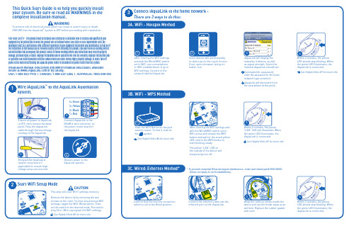
* To prevent potential Ethernet signal interference, order and install part# R0616800. Wrap the cable as shown inside the Within 2 minutes, the yellow“LAN” LED will illuminate. When the green LED illuminates, the iAquaLink is connected.3WARNINGTo prevent risk of electrical shock which can result in severe injury or death, ® system is OFF before proceeding with installation.1Ensure all power to AquaLink is OFF, then remove the dead panel. Pass the iAquaLink cable through the low voltage raceway of the AquaLink.3equipment by the jurisdiction in which the product will be installed where such state or local requirements exist, the maintainer must be a professional with sufficient experience in pool equipment installation and maintenance so that all of the instructions in this manual can be followed exactly. Before installing this product, read and follow all warning notices and instructions that accompany this product. Failure to follow warning notices and instructions may result in property damage, personal injury, or death. Improper installation and/or operation will void the warranty. Improper installation and/or operation can create unwanted electrical hazard which can cause serious injury, property damage, or death. Turn off power at the main circuit feeding the AquaLink power center to disconnect the power center from the system.Installation manual (H0433500) and owners manual (H0433600), available online at or by calling:USA: 1-800-822-7933 | CANADA: 1-888-647-4004 | AUSTRALIA: 1800-688-5523My Network Neighbors NetworkNeighbor #23See Helpful Hints #1 for more infoiFrom under the Manage Pool tab, the pool owner should create a user account with their email address and a password. Then they should sign in to their user account.To download the App, go to and select Mobile Apps - this may appear as a drop-down menu on some devices. It will display links for the appropriate apps for the device. The “Web Application” provides the app experience without downloading or installing1315My Network Neighbors Network Neighbor #23。
Blue Ridge Sauna 安装指南和使用手册说明书

Blue Ridge Sauna Installation & Owner’s ManualRevised December, 2012CHECK YOUR BOXESBe sure to immediately check your boxes against your shipping list and bill of lading. Examine for any damage and and notify Almost Heaven Saunas if there needs to be a repair or replacement of damaged or missing materials.ELECTRICAL REQUIREMENTSAll electrical wiring must be performed by A QUALIFIED LICENSED ELECTRICIAN. Because of the heat involved in the sauna, it is required that you use copper wire with 90ºC insulation. Do not use aluminum wire to make the connection. Consult with an electrician so you can determine the requirements for your particular situation. All wiring must conform to all national, state and local codes and regulations and according to the instructions provided with the heater.LOCATING THE SAUNAYour Blue Ridge Sauna is designed for indoor use. Be sure your sauna is installed on a floor that is firm and flat. In-stalling on carpet is not advised due to both the water that will be used in the sauna as well as the difficulty in assembly on a soft surface. A concrete, tiled or vinyl surface are recommended as ideal surfaces for installation.ASSEMBLYYou should use two people for the assembly of the Blue Ridge Sauna. The wall and roof sections are large and need two people to lift and hold in place during assembly.BASIC TOOLSYou should have the following tools:∙ Cordless drill for driving screws∙ Stepladder or stool∙ Rubber Mallet∙ Claw hammer∙ Screwdrivers (Phillips and Flathead)∙ Framing Square∙ Utility knife∙ Level21. Locate the 4 WALL SUPPORT RAILSThe 4 rails are all identical and will be used to cre-ate the wall support. The rails will support theweight of the sauna but will not be attached to thefloor or assembled sauna walls.NOTE: Be sure your surface is flat before youbegin assembly.Wall Support Rails2. Connect the WALL SUPPORT RAILSConnect the corners using a 2” screw through eachof the 4 pre-drilled holes on the inside of the railgroove.NOTE: Be sure that the rails are square and leveland that the screw head does not protrude into thegroove.Connect Wall Support Rails3. Position completed WALL SUPPORTPlace the completed wall support into position.You will need at least 2’ around each side of thesauna to comfortably complete the assembly.NOTE: Once finished it is possible but not easy toslide the sauna closer to a wall due to the weightof the finished sauna room.Completed Wall Support4. Position WALL SECTION APosition Wall Section A on the left rear side of thesauna according to the guide on ILLUSTRATION1 on following page.NOTE: Wall A should only go as far back in thegroove as shown so that the back wall section Bcan overlap the edge of wall A.Position Wall Section A34 5. Position WALL SECTION B Position Wall Section B on the left rear of the sau-na according to ILLUSTRATION 1.NOTE: Wall Section B will overlap Wall A.Position Wall Section B6. Attach Wall Section B to Wall Section AUsing 2” screws, connect Wall Section B to WallSection A using the pre -drilled holes.NOTE: Be sure the wall edges and top edgesalign evenly.Attach Wall Sections A and BILLUSTRATION 1 The 8 wall sections, A– H, will be positioned in the grooves of the completed wall support section as shown.AB CD E FG H Completed Wall Support7. Position WALL SECTION CPosition Wall Section C on the right rear side ofthe sauna according to the guide on ILLUSTRA-TION 1.NOTE: Wall Section C will attach to Wall Sec-tion B by way of the tongue and groove profile butwill not be fastened with screws.Position Wall Section C8. Position WALL SECTION DPosition Wall Section D on the right rear side ofthe sauna according to the guide on ILLUSTRA-TION 1. Using 2” screws and pre-drilled holes,fasten Wall Section C to Wall Section D.NOTE: As with step 6, be sure the wall edges andtop edges align evenly.Position Wall Section D9. Position WALL SECTION EPosition Wall Section E on the front right side ofthe sauna according to the guide on ILLUSTRA-TION 1.NOTE: Wall Section E will attach to Wall SectionD by way of the tongue and groove profile but willnot be fastened with screws.Position Wall Section E10. Position WALL SECTION FPosition Wall Section F on the right front of thesauna according to the guide on ILLUSTRATION1. Using 2” screws and pre-drilled holes, fastenWall Section F to Wall Section E.NOTE: As with step 6, be sure the wall edges andtop edges align evenly.Position Wall Section F56 Install filler strip to Wall Section F 12. Position WALL SECTION G Position Wall Section G on the left front side of the sauna according to the guide on ILLUSTRA-TION 1. NOTE: Wall Section G will not attach to Wall Section A. Position Wall Section G13. Position WALL SECTION H Position Wall Section H on the front left side of the sauna according to the guide on ILLUSTRA-TION 1. Using 2” screws and pre -drilled holes, fasten Wall Section H to Wall Section G. NOTE: Wall Section H will not attach to the filler strip previously attached to Wall Section F. Position Wall Section H14. Attach WALL CONNECTOR Find the pre -drilled wall connector. Place the wall connector on the top of the front wall edge, bridging walls H, the filler strip, and wall F. Screw it into place with 2” screws.Attach wall connector 11. Install FILLER STRIP Screw the filler strip to Wall Section F to fill the gap between Wall Sections F and H. Optional trim pieces will later be installed over this joint. NOTE: Due to the inherent variations in lumber dimensions, this gap may not be completely filled by the filler piece. This will be addressed later. H15. Build ROOF SUPPORTAssemble 4 roof support rails in the same way youassembled the wall support rails in step 2.NOTE: Be sure that the rails are square and leveland that the screw head does not protrude into thegroove.Completed Roof Support16. Attach ROOF SUPPORT over wallsPosition the completed Roof Support over the wallsections. Once in place on all 4 sides, use 2”screws to attach Roof Support to wall sections.NOTE: Tap the Roof Support firmly in placewith a rubber mallet so wall sections are fully in-serted into the groove before screwing into place.Attach Roof Support over walls17. Position ROOF SECTIONSPlace two Roof Sections on top of Roof Support,nesting the tongue of one section into the grooveof the other. Measure around perimeter before fas-tening to be sure distance from edge is equal.NOTE: Finished side of Roof Sections are to facethe interior of the sauna.Position Roof Sections18. Fasten ROOF SECTIONSUsing 2-1/2” screws, fasten Roof Sections to RoofSupport using pre-drilled holes.NOTE: Be sure to keep even distance from edgeof Roof Section edges and Roof Support edgesaround perimeter of sauna as measured in step 17. Fasten Roof Sections to Roof Support719. Attach ROOF TRIMFind the package of 4 Roof Trim pieces and attachto the raw edge of the Roof Sections with 1-1/2”screws or finish nails.NOTE: The trim pieces are not pre-drilled. Youmay install using screws or finish nails, whicheverstyle you prefer.Attach Roof Trim pieces20. Attach EDGE TRIM - Optional*You can cover the corners of the sauna with EdgeTrim. There are 4 pieces: 4-narrow and 4-wide.Attach with 1-1/2” screws or finish nails, usingone narrow and one wide piece for each corner.Attach the narrow piece first and then overlap withthe wide piece.Attach Edge Trim: OPTIONAL21. Attach WALL TRIM - Optional*There are 6 pieces of wall trim. These can be usedto cover the interior and exterior wall joints be-tween Wall Sections D and E, Wall Sections Hand F, and Wall Sections A and G. Attach with 1-1/2” screws or finish nails.Attach Wall Trim* The use of the Edge Trim and Wall Trim is optional and will not adversely affect the structure or performance of the sauna if not used. Some people prefer the exposed countersunk screw heads on the edge corners and would rather not have the additional trim. This is completely discretionary and should be based on your aesthetic tastes. The Wall Trim may be desired if there is a slight gap between the walls, which can be caused by expansion and contraction of the lumber. Again, it is your choice and will not affect the performance of the sauna. If you choose not to use the trim we suggest you keep it stored in case you decide you want to use it at a later date. Also, we have provided 1-1/2” screws or finish nails. You can use whichever best suits your tastes!822. Attach TOP BENCH SUPPORTSUsing 2” screws, attach the Top Bench Supportsinto Wall Sections A and D using the pre-drilledholes in both the Bench Supports and Wall Sec-tions.Attach Top Bench Supports23. Attach TOP BENCHUsing 2” screws, attach the Top Bench to the ToBench Supports using the pre-drilled holes in theTop Bench.NOTE: The Top Bench is slightly wider than theBottom Bench.Attach Top Bench24. Attach BOTTOM BENCH SUPPORTSUsing 2” screws, attach the Bottom Bench Sup-ports into Wall Sections using the pre-drilled holesin both the Bench Supports and Wall Sections.Attach Bottom Bench Supports25. Attach BOTTOM BENCHUsing 2” screws, attach the Bottom Bench to theBottom Bench Supports using the pre-drilled holesin the Bottom Bench.NOTE: The Bottom Bench will overlap two wallsections on each side of the sauna.Attach Bottom Bench926. Attach Washer to VENT COVERPut a 2” screw through the hole of the vent coverand then place the washer over the screw asshown.Attach Washer to Vent Cover27. Attach VENT COVERScrew the Vent Cover over the vents on Wall Sec-tion B using the pre-drilled hole.NOTE: Tighten only enough so vent cover willturn freely over vents.Attach Vent CoverAttach Door Handles28. Attach DOOR HANDLESThe door handle assembly will consist of the fol-lowing components: 2-Door handles, 1- Male ma-chine screw, 1-Female machine screw, 2-Square Wooden Spacers, and 2-Round Wooden Spacers. Locate the single hole in the glass door. Push one machine screw through one of the pre-drilled han-dles, through a round wooden spacer, through the glass, and into the other machine screw, which has already been pushed through the other door handle and another round wooden spacer. Tighten the screws to a point where the handle is secure on the door, but still rotates freely. With a level, position each of the handles so that they are horizontal and then screw the end of the handles into the hinge board that is attached to the glass door with the wood screws. Now tighten the long machine screws. TAKE CARE THAT YOU DO NOT OVER TIGHTEN AND BREAK THE GLASS.1029. Assembly HEATER FENCEThe Heater Fence consists of four precut,vertically notched posts and six horizontalrails that must be assembled before it isinstalled to the wall adjacent to the heater.The vertical fence posts have slots cut into Heater Fence Assemblythem for the rails. The two vertical fenceposts that go against the wall have slots onjust one face, as well as counter-bored screwholes for attaching them to the sauna wall.The two fence posts that sit away from thewall will have slots cut into two of their faces.Note the beveled ends on the fence rails thatgo into the corner posts. The ends of the rails that go into the fence posts that attach to the wall are square. Assemble the fence before attaching it to the wall by placing the rails into the slots in the posts and using the supplied 1” nails as shown. You may want to put a small amount of wood glue into the slots. Be sure to nail at an angle so that the points will not go through the post. Countersink all nails. Once the fence is assembled, attach it to the wall behind the heater using the supplied wood screws.30. HEATER INSTALLATIONMount the heater as shown in the manufacturer'sinstructions. The heater should be mounted on Wall Sec-tion E, over the vents and 6” from the floor of the sauna.All the necessary hardware is supplied with the heater.Drill a hole below and behind the heater to run the wireand/or conduit according to local electrical codes. Theheater will be hard-wired according the specific wiring re-quirements for your heater.Heater InstallationDo not attempt to wire the heater yourself. Contact a licensed electrician in accordance with your local electrical codes. Heater brand may vary depending on where the sauna was purchased. In-stall sauna stones in accordance with heater manufacturer instructions.Typical wiring requirements for up to 30 feet distance from the breaker box are as follows:4.5kw-6.0kw heaters require 10-2 w/ground, copper only wire, and 30amp non-GFCI breaker.8.0kw and 9.0kw heaters require 8-2 w/ground, copper wire only, and 40amp non-GFCI breaker.Attach Light Fixture 31. Attach LIGHT FIXTUREHave a licensed electrician mount and wire the light fixture (on a separate circuit) into the electrical box mounted in the sauna’s back wall. Do not install your light switch inside the sauna. Rather, install the switch inline outside of the sau-na. If a switch is desired inside the sauna, then it is recommended that you order the special light upgrade from Almost Heaven Saunas that has an integral switch. A standard incandescent bulb will be sufficient, but the heat of the sauna will shorten the life of a normal bulb. An appliance bulb, such as those used in a kitchen oven, will last longer than a standard bulb. Most people prefer subtle, low wattage lighting in the sauna. Do not exceed the wattage recommended by the light’s manufacturer. Do not use compact florescent blubs (also known as CFL bulbs), as the heat of the sauna exceeds the temperatures recommended by florescent bulb manufacturers.32. Duckboard FLOOR SECTIONSThere are 4 floor sections that can be placed in the sauna. These will lay directly on the concrete, tile or vinyl floor that your sauna rests on.The floor sections will sit loose for ease of remov-al. Position them so that any gap between the floor section and wall will be hidden on the back wall and below the benches.Heater Installation Floor Sections33. DOOR HINGE ADJUSTMENTThe tension on the sauna door hinges needs to beset in order for the door to close on its own. Lookfor the small hinge box that is included with yoursauna kit. The hinges have been installed on thesauna, but the box contains both the hex wrenchand set pins needed to adjust your door tension.After the sauna is assembled, and with the doorclosed, take the hex wrench and insert it in the topof the hinge. Once the wrench is fitted into the Adjust tension with hex wrenchhex opening, turn the hex wrench clockwise(toward the wood wall and away from the glass) totighten the hinge tension. You will feel the ten-sion as you tighten. While leaving the hex wrenchinserted and the tension held in place, insert the setpin into the hinge as shown. Repeat the processwith the other hinge as each hinge must be tight-ened to the same degrees of tension.The door should close gently on its own withoutslamming shut. If it does not, then repeat the pro-cess to each hinge to increase the tension further.Save the hex wrench for future adjustment.Insert pin and relax tension to holdTREATING THE SAUNA Western Canadian Red Cedar is naturally resistant to the elements and will retain its natural col-or when not in direct sunlight. If you wish to stain your sauna, your local paint store can rec-ommend a stain for Red Cedar. A stain with a UV inhibitor will retain the full natural color ofthe cedar and is recommended if the sauna will be exposed to sunlight, say, when located by awindow or slider door. Be sure to follow the directions from the stain manufacturer for applica-tion instructions. Never treat the inside of the sauna, and never use varnish or paint on the exte-rior of the sauna.OPERATION After the sauna has been installed, sweep down the inside to remove any sawdust and woodshavings, and then vacuum completely. Using a damp cloth and warm water, wipe down theentire sauna including the benches to remove any remaining dirt, dust and debris. Rinse off thesauna rocks and install them in or on the heater in accordance with the heater manufacturer’sinstructions. Improper placement of heater rocks can result in lower than desired heat tempera-tures. The first time you turn the heater on, set it to the maximum setting and operate it forabout 30 minutes with the door propped open. Then close the door and allow your sauna tocome up to the desired temperature.Since you most likely will use your sauna as both a "wet sauna" and a "dry sauna", you shouldinstall the sauna rocks that have been included with the heater, following the manufacturersinstructions. These stones are necessary if water will be sprinkled on the heater to create the"wet sauna", and they will produce more consistent heating in the dry mode (without the use ofwater). It is common for a stone to occasionally crack during initial heating. If excess amountsof water are used during sauna, prop door open to let the humidity escape. Not much water isnecessary to achieve a “wet sauna”.The amount of ventilation in the sauna can be adjusted by means of the vent located toward thetop of the sauna. It is important to have adequate fresh air flowing through the sauna, and thisflow can be adjusted with the movable vent cover.ACCESSORIES∙ Mount the thermometer on the opposite wall as the heater and 6" from the top of the ceiling.∙ A wooden bucket and ladle are provided for you to sprinkle water over the hot sauna rocks.∙ Optional accessory kit available.Almost Heaven Saunas, LLCMailing Address Shipping AddressP.O. Box 190HC66, Box 465-AMacatawa, MI 49434Highway 219 NorthRenick, WV 24966Sales 888-355-3050Service 304-497.3991Email**********************TAKING A SAUNA BATHThe sauna as we know it comes from Finland. Taking a sauna bath induces excessive perspiration, which cleanses the skin. It stimulates circulation and reduces muscular tension. It can also be an excellent relaxational or social activity.Not to be confused with a steam bath, a sauna is a dry heat bath. The relative humidity rarely exceeds 30% even in a wet sauna. This is because the sauna is made of porous wood and absorbs moisture. This makes higher temperatures more tolerable.Shown below are the steps that are involved in taking a traditional bath. You may or may not want to adhere to this regimen.TRADITIONAL STEPS IN TAKING A SAUNA BATHSTEP #1 - Set your heater so that the sauna room achieves the desired temperature, usually between 150º F and 170º F. As a novice, you should begin at the lower end of this range and work your way up to the higher temperatures over several sauna baths.STEP #2 - Remove all clothing (except maybe your swimsuit), eyeglasses, contact lenses, jewelry, etc. Take a quick shower with warm water and soap, or a quick dip in your hot tub.STEP #3 - Enter the sauna initially for about 5 to 15 minutes. Bring a towel into the sauna onto which you can sit or lay. Leave the sauna room once you have begun to perspire freely.STEP #4 - Now you may take a cold plunge in your swimming pool, shower or snow bank. After that, relax and cool down for another 10 to 20 minutes.STEP #5 - Re-enter the sauna. On this return visit you may wish to sprinkle small amounts of water onto the rocks creating bursts of steam. If the water spills through the heater and onto the floor, you are using too much, although this will not hurt the heater or the sauna.STEP #6 - After your final visit to the sauna, relax for at least 20 minutes. Shower with soap and warm water. Finish your shower with cooler water to close the pores of your skin. Dress only after you have cooled down completely.NOTE: Whatever your sauna regimen, it is important that you keep your self hydrated by drinking plenty of water!。
移动办公赛蓝SGA产品介绍

SGA支持在线视频会议和屏幕共享,让团队成员无论身处何地都能 进行高效的沟通和讨论。
减少差旅成本
由于采用移动办公,员工可以节省大量的通勤时间和费用,降低企业 的差旅成本。
提升管理效率
01
实时监控与汇报
管理者可以通过赛蓝SGA实时了解员工的工作状态和进度,及时调整工
作计划和资源分配。
02
外勤管理
银行外勤人员可实时上报工作进度、处理客户问题,提升外勤工作 效率。
风险评估
通过移动设备进行客户信用评估、风险分析等操作,降低金融风险。
04
成功案例
某大型制造企业
总结词
高效协同,提升生产力
详细描述
该企业通过引入赛蓝SGA移动办公解决方案,实现了各部门的高效协同,员工 随时随地处理工作事务,大幅提升了生产力和工作效率。
统一的信息管理平台
SGA提供统一的信息管理平台,方便管理者整合分散的信息资源,提高
管理效率。
03
高效的数据分析与决策
通过赛蓝SGA收集的数据,管理者可以进行深入的分析和挖掘,为决策
提供有力支持。
增强企业竞争力
创新的工作方式
赛蓝SGA引领企业实现 移动办公的创新模式, 有助于企业在激烈的市 场竞争中脱颖而出。
提高员工满意度
移动办公为员工提供了 更灵活的工作方式,从 而提高员工的满意度和 忠诚度。
吸引优秀人才
赛蓝SGA能够帮助企业 吸引更多优秀的人才, 提升企业整体实力。
THANKS
感谢观看
某知名零售品牌
总结词
优化库存管理,提升客户体验
详细描述
该零售品牌利用赛蓝SGA的库存管理功能,实现了实时库存监控和智能调度,有 效提升了库存周转率,同时优化了客户购物体验。
赛蓝SGA用户手册2.4

SSL用户手册版本(2.4)目录一 、客户端环境要求 (2)二、控件安装及资源访问页面说明 (3)三、3G 应用资源访问 (7)四、CAB 应用资源访问 (8)五、TCP 隧道资源访问 (9)六、IP 隧道资源访问 (10)七、PPTP 资源访问 (13)八、单点登录资源访问 (14)九、消息公布资源栏 (15)一、客户端环境要求客户机推荐使用的操作系统:Windows2000 professional/Windows 2000 server/Windows 2003 server/Windows xp/Windows xp SP2 以上。
客户机推荐浏览器:IE6.0以上。
如要用到CAB 应用资源,需要先在客户机上装JAVA 插件,可在SUN 公司的官方网站下载。
二、控件安装及资源访问页面说明外网用户可以通过域名访问资源,在IE 地址栏输入https:// ,第一次登录使用SSL 的用户,在进登录界面前需要先装一个integrate 控件,只有用户装上该控件后才能正常登录和使用SSL,当开打IE 窗口,在地址栏输入https:// 点击回车后,会出现一下界面:右击黄色条,点安装ActiveX 控件,如下图:接着出现如下界面,点击安装:点击安装后,会出现更新安装控件的进度条,如下图所示:控件更新完毕自后就会进入到前台登陆界面:可以看到,页面中右上角可以更换语言版本,我们SSL VPN 有3 个语言的版本。
在页面的左上角有卸载控件按钮,使用该按钮可以轻松快捷的卸载掉第一次登陆时所安装的控件,使设备用起来更方便。
安装完后,将会自动关于IE,重新开启一个IE 页面登录到SSL 前台登录界面,如下图:输入用户名:demo ,密码:111111如下面所示前台页面:顶端右上角有4 个链接,分别是更改密码,证书请求,帮助,退出。
更改密码:用户可以更改自己的登录密码。
证书请求:该链接为证书请求工具,用户可以使用此工具生成证书请求文件和用户私钥。
赛斯纳152手册(中文版)

赛斯纳152第一节总论简介本手册有九节内容,包括民航规章/条例第三部分中要求提供给飞行员的材料和赛斯纳公司提供的补充资料。
第一节提供了一些基本数据和使用者广泛关注的信息,同时还包括一些符号、缩写和常用术语的定义或解释。
描述性资料发动机发动机数:1发动机生产厂家:Avco Lycoming发动机型号:O-235-L2C发动机种类:正常进气、直接驱动、气冷式、水平队列式、配备化油器、233.3立方英寸排量的四气缸发动机。
马力等级和发动机速度:2550转每分下110额定制动马力.螺旋桨螺旋桨生产厂家:McCauley 零件公司螺旋桨模型数:1A103/TCM6958桨叶数:2螺旋桨直径:最大直径:69英寸最小直径:67.5英寸螺旋桨类型:固定桨距燃油认可的燃油等级(及颜色):100低铅航空燃油(蓝色)100(以前100/130)等级航空燃油(绿色)燃油容量:标准油箱总容量:26加仑每箱总容量:13加仑总可用燃油:24.5加仑远程油箱总容量:39加仑每箱总容量:19.5加仑总可用燃油:37.5加仑注:由于在油箱间可以交叉输油,每次注油后应重新灌满油箱以保证最大容量。
滑油滑油等级(规格):MIL-L-6082 航空等级中的纯矿物滑油用于最初25小时和首次飞行25小时换油时的补充供给。
飞机飞行50小时或消耗稳定前可继续使用。
注意飞机出厂交付使用时配有发动机防腐滑油,应在首次操作25小时后消耗完毕。
MIL-L-22851 无烟稀释滑油应在飞机飞行50小时后或消耗稳定后使用。
温度范围内的建议黏度:MIL-L-6082航空等级中的纯矿物滑油16℃(60℉)以上 SAE:50-1℃--32℃之间(30℉--90℉) SAE:40-18℃--21℃之间(0℉--70℉) SAE:30-12℃(10℉)以下 SAE:20MIL-L—22851无烟稀释滑油16℃(60℉)以上 SAE:40或50-1℃--32℃之间(30℉--90℉) SAE:40-18℃--21℃之间(0℉--70℉) SAE:30-12℃(10℉)以下 SAE:30滑油容量:集油槽:6夸脱总量:7夸脱(如果滑油过滤器已安装)最大允许重量:停机重量:1675磅起飞重量:1670磅降落重量:1670磅行李间重量:第一行李区(或在儿童座席)站位为50至76,120磅。
深圳市赛蓝 SGA 技术白皮书
赛蓝SGA技术白皮书深圳市赛蓝科技有限公司 Shenzhen Cylan Technology Co., Lt d2009年2月目录序言 (4)一、CYLAN SGA产品简介 (5)二、CYLAN SGA功能介绍 (7)2.1 SSL 应用发布 (7)2.1.1 B/S软件的应用 (7)2.1.2 企业站点的应用 (7)2.1.3 单点登录功能(SSO) (8)2.1.4 C/S应用发布 (9)2.1.5 TCP端口应用 (10)2.1.6 SSL隧道模式 (10)2.2 LAN TO LAN 的解决方案 (10)2.3 远程用户安全性检查 (11)2.4 远程用户访问认证 (11)2.5 日志审计功能 (12)2.6 防火墙功能 (12)2.7 支持动态IP接入 (12)2.8 完美的个性化定制 (13)三、CYLAN SGA 工作原理和组网方式 (14)3.1 SSL协议介绍 (14)3.2 SGA技术实现 (15)3.3 CYLAN SGA 原理和网络拓朴图 (17)四、CYLAN SGA的技术优势 (19)4.1 将C/S应用转成B/S访问 (20)4.2 WEB应用功能 (20)4.3 访问的安全性 (20)4.4 稳定性及高可用性 (21)4.5 低带宽运行特性 (21)4.6 布署灵活,维护简单 (22)4.7 远程唤醒功能 (22)五、CYLAN 安全网关的产品介绍 (23)附录 CYLAN SGA功能表 (25)序言当前大多数远程访问解决方案是利用基于IPSec安全协议的VPN网络的情况下,一种最新的研究表明近乎90%的企业利用VPN进行的内部网和外部网的联接都只是用来进行因特网访问和电子邮件通信,另外10%的用户是利用聊天协议和其它私有客户端应用,属非因特网应用。
而这些90%的应用都可以利用一种更加简单的VPN技术--SGA来提供更加有效的解决方案。
基于SSL协议的VPN远程访问方案的更加容易配置和管理,网络配置成本比起目前主流的IPSec VPN还要低许多,所以许多企业已经开始转而利用基于SSL加密协议的远程访问技术来实现VPN通信了。
移动办公解决方案--赛蓝

赛蓝移动办公解决方案目录1行业背景 (5)2行业需求 (5)3解决方案 (6)3.1产品介绍 (6)3.2部署方式 (7)3.2.1网关模式 (7)3.2.2单臂模式(推荐) (7)3.3安全机制 (8)3.3.1服务器安全 (9)3.3.2传输安全 (9)3.3.3接入安全 (9)4方案优势和价值 (11)4.1低成本短周期 (11)4.2提高决策能力和反应速度 (11)4.3有效提升产能 (12)4.4远程应用加速 (12)4.5保护企业核心资源 (12)4.6降低企业管理成本 (12)5成功案例 (13)5.1某铁路局某客运段移动云办公项目 (13)5.2佛山市南庄镇人民政府 (14)5.3项目列表 (14)6附录 (15)6.1附录一赛蓝简介 (15)6.2附录二安装环境 (15)图1移动云接入管理平台 (7)图2前置机软件 (7)图3手机客户端软件 (7)图4移动办公系统部署图示 (8)图5移动办公系统拓扑图 (8)图6端到端的安全保障 (8)图7 某客运段移动办公界面 (13)图8南庄镇电子政务系统界面 (14)图9项目列表(部分) (14)1 行业背景2009年3G业务正式商用以来,三大运营商都在积极布局;随着国家对WLAN的逐渐放开,WiFi热点像雨后春笋般涌现。
这些都为智能移动终端的应用提供了很大的空间。
据CNNIC的《第30次中国互联网发展状况调查统计报告》,在2012年上半年,通过手机接入互联网的网民数量达到3.88亿,相比之下台式电脑为3.80亿,手机成为了我国网民的第一大上网终端。
移动通信技术和互联网技术的快速发展以及两者的紧密结合,使得移动办公成为可能,两者相互促进,共同发展。
随着企业信息化进程的加速,各个企业为了提高工作效率,规范企业运作,都在积极部署各种应用如邮件系统、ERP系统、OA办公自动化系统和CRM系统等。
如何利用手机的方便性优势,使企业用户获得高效、快捷和安全的信息化应用环境,使得用户可以随时随地接入公司系统处理一切事务成为亟待解决的一个问题,这些都为移动办公提供了良好的环境和现实需求。
Saia-Burgess空调系统用户手册说明书

- 6 -WEEE Directive 2012/19/EC Waste Electrical and Electronic Equipment directiveAt the end of the product life dispose of the packaging and p roduct in a corresponding recycling centre. Do not dispose of the unit with the usual domestic refuse.Do not burn the product !RECOMMENDATIONS AND RULES►Rules regarding electrostatic discharge should be followed. ►If the device is modified in any way, except by the manu -facturer, all warranties concerning operation and safety are invalidated.►Make sure that the local standards and regulations areobserved at all times. Examples of such regulations are VDE 0800 and VDE 0100 or EN 60204-1 for earth grounding.►Use only accessory equipment which comes from or has been approved by Honeywell.►It is recommended that the device be kept at room temper-ature for at least 24 hours before applying power. This is to allow any condensation resulting from low shipping / storage temperatures to evaporate.►The device must be installed in a manner (e.g., in a lockable cabinet) ensuring that uncertified persons have no access to the terminals.►Do not open the device, as it contains no user-serviceable parts inside!►The device is suitable for mounting in fuse boxes conforming to standard DIN 43880, and having a slot height of max. 45 mm.►The device is suitable for panel rail mounting on 35 mmstandard panel rail (both horizontal and vertical rail mounting possible) – see pictures 0G and 0H.STANDARDS, APPROVALS, ETC.PURPOSE OF CONTROL: OPERATING CONTROL and multifunctional non-safety control intended for HVAC in home (residential, commercial, and light-industrial) environments ■24 V models:UL 60730-1, Standard for Automatic Electric Controls for Household and Similar Use, Part 1: General Requirements ■CE-approved■FCC part 15B-compliant.CONSTRUCTION OF CONTROL: Independently mounted electronic control unit with fixed wiring. Panel-mounted on a DIN rail.SHOCK PROTECTION: Class II.POLLUTION DEGREE: 2.RATED IMPULSE VOLTAGE: ■230 V circuits: 2500 V ■ 24 V circuits: 500 V NOTE:K eep AC mains supply/load cables separate from signal wiring!RELAY SPECIFICATIONSCAUTIONRISK OF ELECTRICAL SHOCK OR EQUIPMENT DAMAGES!It is not permitted to combine low voltage and line voltage in the relay block.MU1B-0643GE51 R0418C - 5 -Saia Burgess Controls AGPCD7.LRxx-P5 PG5 ROOM CONTROLLER - MOUNTING INSTRUCTIONS EKeep these instructions together with the device or with the equip-ment documentation!FCette instruction est à conserver avec le contrôleur ou avec la docu-mentation de l’installation !PGuarde estas instruςões junto do regulador ou junto da documentaςão da instalaςão!D Diese Anleitung ist beim Gerät oder in der Anlagendokumentation aufzubewahren!IQueste istruzioni devono essere conservate insieme al lettore o con la documentazione dell´impianto!S Denna instruktion skall förvaras tillsammans med regler eller anlägg-ningsdokumentationen!DKOpbevar denne vejledning sammen med regler eller med anlægsdoku-mentationen!N Denne veiledningen skal oppbev-ares sammen med regler eller anleggs-dokumentasjonen!FITätä ohjetta tulee säilyttää laitteen läheisyydessä tai yhdessä muiden dokumenttien kanssa!ES Conserve estas instrucciones con el recalar con la documentación de la instalación.NL Deze handleiding moet bij de rege-laar, of met de documentatie van de installatie worden bewaard!PLInstrukcję obsługi należy przechowy -wać przy urządzeniu albo w doku -mentacji technicznej.Copyright © 2018 Saia-Burgess Controls AG All Rights ReservedMU1B-0643GE51 R0418CSupportDocumentationMU1B-0643GE51 R0418C - 4 -Saia Burgess Controls AG PCD7.LRxx-P5 PG5 ROOM CONTROLLER - MOUNTING INSTRUCTIONS2. D IN-RAIL MOUNTING PCD7.LRxx-P5 + MOUNTING IRM-RxC3. DISMOUNTING IRM-RxC + DISMOUNTING PCD7.LRxx-P5 from DIN-RAILMU1B-0643GE51 R0418C - 3 -Saia Burgess Controls AG PCD7.LRxx-P5 PG5 ROOM CONTROLLER - MOUNTING INSTRUCTIONS- 2 -Saia Burgess Controls AG PCD7.LRxx-P5 PG5 ROOM CONTROLLER - MOUNTING INSTRUCTIONS MU1B-0643GE51 R0418C。
南方s750说明书

S750 G2 使用手册
5.1.3 坐标系统设置....................................................................... 35 5.1.4 实时设置 .............................................................................. 36 5.2 调试网络 ......................................... 40 5.3 创建文件,进行作业................................ 41 5.4 坐标转换 ......................................... 48
2.2 开机使用 .......................................... 7 2.2.1 开机 ........................................................................................ 7 2.2.2 关机 ........................................................................................ 8
2.3 与电脑的连接....................................... 8 2.4 校正触摸屏......................................... 8 2.5 重新启动 S750 G2 主机............................... 8
1.1 产品指标 .......................................... 1 1.2 产品特点介绍....................................... 3 1.3 配置单 ............................................ 4
赛普拉斯nvSRAM产品说明书

CY14V101PS 带有实时时钟的1 Mbit(128K x 8)四线SPI nvSRAM特性■容量❐1 Mbit(128K × 8)■带宽❐提供速率为108 MHz的高速接口❐支持以54 Mbps的速度进行读写操作■串行外设接口❐时钟极性和相位模式0和3❐多个I/O选项 — 单线IO模式中的SPI(SPI)、双线IO模式下的SPI(DPI)以及四线IO模式下的SPI(QPI)■可靠性较高❐无限次读、写和回读周期❐一百万次的存储周期,用于将数据存储到SONOS FLASH Quantum trap中非易失性单元内❐数据保留时间:温度为85°C时保留20年■读取❐命令:正常、快速、双线I/O以及四线I/O❐模式:突发包、持续(XIP)■写入❐命令:正常、快速、双线I/O以及四线I/O❐模式:突发循环■数据保护❐硬件:通过写保护引脚(WP)提供保护功能❐软件:通过写禁用指令提供保护❐块保护:状态寄存器位用于控制保护■特殊指令❐STORE/RECALL:用于在SRAM 和Quantum Trap nvSRAM 间传输数据❐序列号:用户可选的8字节(OTP)❐标识号:4字节的制造商ID和产品ID■支持将数据从SRAM存储到非易失性SONOS FLASHQuantum Trap内❐自动存储:断电时,通过使用小电容(V CAP)自动存储数据❐软件:使用SPI指令(STORE)❐硬件:使用HSB引脚进行存储■支持将数据从非易失性SONOS FLASH Quantum Trap回读到SRAM内❐自动回读:加电时,自动开始回读❐软件:使用SPI指令(RECALL)进行回读■低功耗模式❐睡眠:温度为85 °C时,平均电流为380 µA❐休眠模式:温度为85 °C时,平均电流为 8 µA■供电电压的工作范围❐内核电压V CC:2.7 V ~ 3.6 V❐I/O电压V CCQ:1.71 V ~ 2.0 V ■温度范围❐工业级:–40 °C~85 °C■封装❐16-SOIC功能概述赛普拉斯CY14V101PS将1 Mbit nvSRAM与QPI接口相结合。
赛蓝移动办公平台快速配置手册

赛蓝移动办公平台快速配置手册一、设备的接口配置赛蓝移动办公平台SGA1000的接口出厂IP参数如下:ETH0:192.168.0.254ETH1:192.168.1.254Console:波特率38400二、首次配置赛蓝移动办公平台是基于WEB的配置方式,默认管理员端口是4433,管理员账号是admin, 密码是111111, 首次可以通过默认的IP进入管理界面(注意在本机添加0网段或者1网段的IP),设备默认进入方式如下:https://192.168.0.254:4433或https://192.168.1.254:4433三、修改SGA各网口IP以适合用户具体需求,配置网关和DNS信息。
四、网络测试配置好设备网络信息后,在设备内部做网络测试,看是否能ping通外网域名和内网待发布的服务器。
五、如果设备放在防火墙和路由器后面,需在前端防火墙或路由器上做端口转发(如果设备有固定公网IP,则可以省略此步骤),需要映射的端口如下:TCP 443 (用户使用)TCP 4433(后台管理)TCP 自定义(IP隧道使用端口)TCP 自定义(TCP隧道使用端口)如需用到IPSec需转发UDP 500和UDP4500端口。
六、发布手机应用进入设备后台管理页面,打开【应用发布】——【CAB应用】,点击【添加】,填好应用的名称、服务器的IP地址、服务器的WINDOWS账号、密码,如发布一个B/S的程序(OA或web),需在【登录后的工作目录】里面填IE的路径,为C:\Program Files\Internet Explorer,在【登录后启动程序】里面填IE的可执行文件名称,即IEXPLORE.EXE (此处为要发布的OA的URL),如下图:如发布一个C/S的程序(如ERP),需在【登录后的工作目录】里面填ERP 程序的路径,在【登录后启动程序】里面填IE的可执行文件名称,xxx.exe.(此处为要发布的ERP的exe文件),如下图:应用账户选择方式:使用手动绑定账号如选择这一项,表示应用账户可以与iServer上具有远程桌面登录权限的账号,进行手动绑定,拥有相应资源使用权限的特定用户组中的用户可以手动绑定Windows登录账号,需要在CAB用户绑定页面进行相应绑定,此处的SGA设备前台登录用户名、密码和绑定Windows登录账号、密码可以不同。
蓝斯通 客运出租版车载终端 产品使用说明

产品使用手册 GPS 客运出租版车载终端
厦门蓝斯通信有限公司
XIAMEN LENZ COMMUNICATION CO., LTD
Байду номын сангаас目录
第一章 产品简介..............................................................................................................................................................................................................................................................1 1.1 产品概述..............................................................................................................................................................................................................................................................1 1.2 技术参数...............................................................................................................................................................
GasAlertMax_使用说明书(中文)

设定下限告警设定点 .................................................... 29
设定上限告警设定点 .................................................... 30
设定剩余的告警设定点 ......................................................................................... 31
BW Technologies 的保证是有限的,在保用期间退回 BW Technologies 授权服务中心的损坏产品,BW Technologies 有 权决定采用退款、免费维修或把产品更换的方式处理。
欲取得保证服务,请和您附近的 BW Technologies 服务中心联系,或把产品寄到最靠近您的 BW Technologies 服务中心 (请说明故障所在,预付邮资和保险费用,并以 FOB 目的地方式寄送)。BW Technologies 不负责产品在运输上的损坏。保 用期修理以后,BW Technologies 会将产品寄回给购买者(预付运费,并以 FOB 目的地方式寄送)。如果 BW Technologies 判断产品的故障是由于误用、改装、意外或非正常情况下的使用或搬运而造成,BW Technologies 会对维修费用作出估价, 并取得购买者的同意以后才进行维修。维修后,BW Technologies 将把产品寄回给购买者(预付运费、FOB 运输点),同时向 购买者征收维修和运输的费用。
检测器维护.................................................................. 34
RG-ACE系列应用控制引擎ARAS用户手册

RG-ACE 应用控制引擎 网络应用实时分析系统
版 权 声 明
福建星网锐捷网络有限公司 ©2009 版权所有,保留一切权利。 没有经过本公司书面许可, 任何单位和个人不得擅自摘抄、 复制本书内容的部分或者全部 , 并且不得以任何形式传播。
、 、
、
、
、 、
、
都是福建星网锐捷网络有限公司的注册商标,不得仿冒。
RG-ACE 应用控制引擎网络应用实时分析系统用户手册目来自1录2
3
网络应用实时分析系统简介.............................................................................................................................. 2 1.1 主要特性.................................................................................................................................................. 2 1.1.1 图形界面,一键式操作.............................................................................................................. 2 1.1.2 多工作桌面架构.......................................................................................................................... 2 1.1.3
SGAS15E系列产品说明手册说明书

3 years : 100% load 40℃, 12hours / day
MTBF OTHERS
DIMENSION
PACKING
PLUG CONNECTOR
CABLE
507Khrs min. MIL-HDBK-217F(25℃) 75.6*42.1*24.7mm (L*W*H) 130g ; 72pcs / 11Kg / CARTON See page 4~5 ; Other type available by customer requested See page 4~5 ; Other type available by customer requested
OVERLOAD PROTECTION
OVER VOLTAGE
WORKING TEMP.
105 ~ 250% rated output power Protection type : Hiccup mode, recovers automatically after fault condition is removed >120% rated output voltage Protection type : Clamp by zener diode -20 ~ +70℃ (Refer to "Derating Curve")
series
Derating Curve
100 80 65 50
-20 -10 0 10 20 30 40 50 60 70
AMBIENT TEMPERATURE (℃)
Mechanical Specification
Static Characteristics
100 90 80 70 60 50 40
Lead Acid Smart Charger 2.5A用户手册(适用于36V铅酸电池,100V-2

User Manual ofLead Acid Smart Charger (2.5A) for 36V Lead AcidBattery, 100V-240V ACAA Portable Power Corp ()Address: 860 S, 19th St, Unit A, Richmond, CA, 94804Tel: 510-525-2328Fax: 510-439-2808Email:**********************Prepared & Approved by Max (10/01/11)Features:•Intelligent charger designed for 36V Lead acid Battery with capacity > 2.5Ah•Worldwide input AC power from 100-240VAC, 50-60Hz, USA AC plugo For international use, please click here to order AC plug adaptor seperately •Built in cooling fan to ensure charger long service life•Safety protectiono Over Voltage protectiono Short Circuit protectiono Output reverse protection•Charging Currento 2.5A standard charging rate•Output: Output: 43.8VDC•Max Power output: 120W•Approximate Charging time:o Approximate Charging time = (1.5 x Ah rate of the pack) / 6.0A charge current.•Built in IC to cut off power automatically when battery is fully charge.•LED indicator:o LED1 = Red = Power On, Remain on during the whole operationo LED2 = Red = Chargingo LED2 = Green = Fully Charged•Note:You must connect charger to AC power before connect to battery pack. Otherwise, the charger will NOT charge the pack and you will not get a RED LED indicate charging.•Red LED show Battery charging and Green LED shows full.•Charging terminal : 4 pin female cannon plugCharging terminal: Pin #1,2 = negative, Pin#3,4 = positiveExcluded 1 pc of 4 Pin male Cannon plugIncluded 1 pc of Connector/Adaptor: From 4 Pin male Cannon plug to ClipsNeed to charge the pack with Standard Male Tamiya charging terminal?Pleaseclick here to order the connector adaptor seperately.o Warning: Wrong polarity will damage the charger. Batteryspace is notresponsible for the damage or losses caused by misusing•Included 2 pcs 10.0A replacement fuse•Dimension (LxWxH): 155mm(")x 92mm(3.6")x52mm(2.0")•Weight: 1.0 lbs 15.6Oz (900g)Operation Instruction:1.Connect the charger to AC outlet( LED1 = Red = Power On, Remain on during the wholeoperation, and LED 2 = Green)2.Connect the DC output cord to battery terminals (LED 2 will turn Red indicate charging, Red= V+, Black = V-)3.Charging terminal: Pin 1 & 2 = Negative, Pin 3 & 4 = Positive4. When LED 2 turn green, battery is fully chargedWarning:•Only charge SLA battery pack with capacity > 2500 mAh. Don't use the charger for lower capacity SLA battery pack.•Only charge Lead acid battery pack with voltage 36V. Don't use the charger for Lower voltage battery pack which may cause battery to explode•We are not responsible for any damage caused by misuse.•Indoor use only•Don't remove the case to prevent from electric shock•Unplug the charge from AC outlet after use.Picture:Built in with Cooling Fan。
移动办公赛蓝SGA产品介绍

第11页
◆ 细致的用户权限管理:根据用户分配接入权限和访问权限,提供基于用 户、用户组、角色、资源等多种方式的权限控制;管理员分级权限管理; 实时监控用户接入情况,可进行并发限制、用户中断等操作 ◆ 灵活的授权策略 通过序列号进行功能和许可管理,给予用户角色时间 进行任意组合的访问策略 ◆ 配置备份,导入导出,在线升级
赛蓝科技
SGA产品功能介绍
赛蓝SGA产品功能组成
第2页
SSL VPN IPSEC VPN
CYLANLL防火墙
SSL VPN功能
SSL安全协议介绍
第3页
• SSL安全协议最初是由Netscape Communication公司设计开发的,又叫 “安全套接层(Secure Sockets Layer) 协议”,主要用于提高应用程序之间的 数据的安全系数。SSL协议的整个概念 可以被总结为:一个保证任何安装了安 全套接字的客户和服务器间事务安全的 协议,它涉及所有TC/IP应用程序。
易管理性
第13页
◆ Web管理界面:支持SSL加密的WEB界面进行设备配置和管理,支持 简体中文\繁体中午\英文界面 ◆ SNMP:集成第三方管理系统,实现更强大的监控功能 ◆ 系统日志:提供详细的审计和日志功能。记录访问内容请求,用户访问 的时间、访问地址等信息,提供详细的系统信息,调试及错误日志,支持 与第三方Syslog日志服务器同步 ◆ 接入方式:支持单双臂模式,组网灵活
Q&A
SSL协议特点
合法性认证 认证用户和服务器的合法性,使得它们能够确信数据将 被发送到正确的客户机和服务器上。客户机和服务器都 是有各自的识别号,这些识别号由公开密钥进行编号, 为了验证用户是否合法,安全套接层协议要求在握手交 换数据进行数字认证,以此来确保用户的合法性。
赛克蓝德日志分析软件用户手册

赛克蓝德日志分析软件用户手册南京赛克蓝德网络科技有限公司重要声明1、使用本产品必须严格遵照本用户手册的详细描述操作。
为确保您正确使用本产品,请在安装前详细阅读本用户手册,避免出现不必要的问题。
2、若因使用或不能使用本产品而产生的任何损害(包括间接个人损害、商业利润的损失、营业中断、商业信息的遗失、或其它任何金钱上的损失),本公司不负任何损害赔偿责任。
版权声明您购买或者免费使用本产品并不意味着南京赛克蓝德网络科技有限公司对其享有的知识产权也进行了转让。
本产品(包括但不限于本产品中所含的任何商标、图像、照片、动画、录影、录音音乐、文字和附加程序)随附的印刷材料及南京赛克蓝德网络科技有限公司授权您制作的任何副本均为南京赛克蓝德网络科技有限公司的产品,其知识产权归南京赛克蓝德网络科技有限公司所有。
本产品的结构、组织和代码均为南京赛克蓝德网络科技有限公司的商业秘密和保密信息。
本产品受中华人民共和国著作权法、相关国际条约以及使用本产品国家所适用的法律的保护。
未经书面授权,禁止将本产品以任何方式进行复制、修改、出租、租赁、出借、转让本产品或其中的任一部份。
禁止将本产品进行反向工程、反向编译、反汇编或以其它方式尝试发现本产品的源代码。
南京赛克蓝德网络科技有限公司保留在任何时候通过为您提供本产品的替换、修改版本或升级收取费用的权利。
南京赛克蓝德网络科技有限公司保留对本手册内容在未预先通知的情况下作出修改的权利,如有改动,恕不预先通知。
目录赛克蓝德日志分析软件 (1)用户手册 (1)目录 (4)产品介绍 (6)产品结构图 (6)安装 (7)系统运行 (8)常用问题 (8)安装完成 (8)使用指南 (9)功能说明 (10)WEB系统登录 (10)菜单介绍 (13)首页 (14)安全监控 (17)审计报表 (20)资产管理 (28)安全配置 (34)系统管理 (41)系统监控 (45)日志源配置 (47)Linux syslog客户端配置 (47)Window日志发送配置 (48)IIS日志发送配置 (51)Snmp trap的配置 (53)httpsniffer采集 (53)Mysql日志审计 (54)Vsftp日志 (54)Sftp日志 (54)inotify日志配置 (55)Collectd配置 (55)业务日志分析 (58)格式介绍 (58)代码示例 (59)技术支持 (60)产品介绍赛克蓝德日志分析软件(简称:seci-log)是日志收集分析软件,可以收集日志,支持syslog、snmp、jdbc、ftp/sftp等协议收集或者采集日志。
- 1、下载文档前请自行甄别文档内容的完整性,平台不提供额外的编辑、内容补充、找答案等附加服务。
- 2、"仅部分预览"的文档,不可在线预览部分如存在完整性等问题,可反馈申请退款(可完整预览的文档不适用该条件!)。
- 3、如文档侵犯您的权益,请联系客服反馈,我们会尽快为您处理(人工客服工作时间:9:00-18:30)。
SSL用户手册
版本(2.5)
目录
一 、客户端环境要求 (2)
二、控件安装及资源访问页面说明 (3)
三、3G 应用资源访问 (7)
四、CAB 应用资源访问 (8)
五、TCP 隧道资源访问 (9)
六、IP 隧道资源访问 (10)
七、PPTP 资源访问 (13)
八、单点登录资源访问 (14)
九、消息公布资源栏 (15)
一、客户端环境要求
客户机推荐使用的操作系统:Windows2000 professional/Windows 2000 server/Windows 2003 server/Windows xp/Windows xp SP2 以上。
客户机推荐浏览器:IE6.0以上。
如要用到CAB 应用资源,需要先在客户机上装JAVA 插件,可在SUN 公司的官方网站下载。
二、控件安装及资源访问页面说明
外网用户可以通过域名访问资源,在IE 地址栏输入https:// ,第一次登录使用SSL 的用户,在进登录界面前需要先装一个integrate 控件,只有用户装上该控件后才能正常登录和使用SSL,当开打IE 窗口,在地址栏输入https:// 点击回车后,会出现一下界面:
右击黄色条,点安装ActiveX 控件,如下图:
接着出现如下界面,点击安装:
点击安装后,会出现更新安装控件的进度条,如下图所示:
控件更新完毕自后就会进入到前台登陆界面:
可以看到,页面中右上角可以更换语言版本,我们SSL VPN 有3 个语言的版本。
在页面的左上角有卸载控件按钮,使用该按钮可以轻松快捷的卸载掉第一次登陆时所安装的控件,使设备用起来更方便。
安装完后,将会自动关于IE,重新开启一个IE 页面登录到SSL 前台登录界面,如下图:输入用户名:demo ,密码:111111
如下面所示前台页面:顶端右上角有4 个链接,分别是更改密码,证书请求,帮助,退出。
更改密码:用户可以更改自己的登录密码。
证书请求:该链接为证书请求工具,用户可以使用此工具生成证书请求文件和用户私钥。
帮助:用户使用手册。
退出:退出SSL 系统前台。
列表模式,图标模式:用户更改前台资源显示风格。
应用列表:下面将列出用户可访问的资源。
欢迎信息将记录登录的
用户名和该用户上次登录的IP 地址和时间。
在登陆前台后,可以看到右下角处有一个更改TCP 模式的按钮,如果用户能够正常安装控件则不需要点击它,如果不能正常安装控件,可以尝试点击改变TCP
模式来安装。
登录后,进入以下界面,要访问3G 应用,可以直接点击中间访问地址下的蓝色字样的3G。
默认进去的前台显示风格是列表模式(管理员可在控制台调整),用户可以根据自己的喜好切换到图标模式。
图标模式则直接点击3G 上面的图片即可。
登录后,进入以下界面,要访问CAB 应用,可以直接点击中间访问地址下的蓝色字样的CAB。
默认进去的前台显示风格是列表模式(管理员可在控制台调整),用户可以根据自己的喜好切换到图标模式。
图标模式则直接点击CAB 上面的图片即可。
注意:该应用需要JAVA 插件的支持,即客户机上需要先装JAVA 控件。
成功安装控件后登录,界面显示如下:蓝色字体显示出来的是可以直接点击的链接,用户显示可以按照访问地址下的提示访问需要访问的TCP 资源了。
默认进去的前台显示风格是列表模式(管理员可在控制台调整),用户可以根据自己的喜好切换到图标模式。
图标模式则直接点击TCP_http 上面的图片即可。
注意:图标模式只能显示可以直接点击的链接,对于用文字来说明的应用无法在图标模式下显示。
六、IP 隧道资源访问
第一次登录前台,用户首先需要安装虚拟网卡,如下图,点击仍然继续。
安装成功后,网卡会自动连接上,便在页面上显示客户端获得的虚拟IP 地址,
如下图:
虚拟网卡可在网上邻居里面查看到,如下图:本地连接1 就是新装的虚拟网卡,并且是处于连接状态。
默认进去的前台显示风格是列表模式(管理员可在控制台调整),用户可以根据自己的喜好切换到图标模式。
图标模式则直接点击IP_http 上面的图片即可。
注意:图标模式只能显示可以直接点击的链接,对于用文字来说明的应用无
法在图标模式下显示。
在以上应用中,资源显示的图片都采用的是默认的图片,用户可以根据自己的喜好,在后台的应用发布--图片管理中上传不同图片,并在发布应用时选择
配置不同的图片。
例如:
七、PPTP 资源访问
进入前台后,用户可在本地网络连接里面查看到一个名称为conn_ssl 的虚拟专用网络,如下图:此时,该虚拟专用网络处于连接状态,在客户机任务栏的右下角也可以看到一个处于活动状态的电脑下图标,即表示您的PPTP 连接已经建立成功,用户可访问到服务器端的资源。
如退出SSL 前台界面,则该虚拟专用网络连接断开,任务栏右下角的电脑图标消失,但是网络连接里面的conn_ssl 虚拟专用网络连接不会消失,,只是处于未连接状态,如下图:
八、单点登录资源访问
登录后,进入以下界面:
用户第一次使用,先点击重新配置,输入您的登录OA 系统的用户和密码,如下图,输入好后点击确定则以后访问OA 时,用户无须输入用户名和密码,点击蓝色字样的OA 便可直接登录到OA 系统里进行操作。
默认进去的前台显示风格是列表模式(管理员可在控制台调整),用户可以根据自己的喜好切换到图标模式。
图标模式则直接点击OA 上面的图片即可。
如下图:注意:只有列表模式下才有重新配置链接,如果用户需要修改下次登OA 系统的用户名密码,请先切换到列表模式配置好后,再切换到图标模式下访问。
九、消息公布资源栏
管理员在后台配置好需要公布的消息,用户登陆后即能看到消息,如下图所示:。