Q67000-S28中文资料
PW7000-系列Access控制系统用户指南说明书

PW7000-SERIES T he PW7000-Series AccessControl System is an advancedaccess control hardwarearchitecture capable of providingsolutions for large enterpriseapplications.Controllers and I/O BoardsFEATURES AND BENEFITSSECURE• L atest encryption standard support with TLS1.2 and OSDP (V2) Secure Channel Protocol• E mbedded Crypto Memory Chip to protect sensitive data VERSATILE• B ackwards compatible withPW6000* controllers, readerboards, I/O boards andenclosures*• O n-board support for up to2 readers (1 Door) for bothPW7K1IC and PWLP1501COMPREHENSIVE• W ide variety of nativeintegrations includingwireless locks and destinationdispatch elevators• E xtensive customizationincluding If / Then macrocapabilitiesADAPTABLE• M odular design allowscontrollers and downstreamboards to be mixed to fit themost demanding customerrequirements• F lexible power options forPWLP1501 and PWMR62Eincluding PoE and PoE+The Intelligent Controllers provide power and flexibility with an embedded Linux OS, improved processor and increased memory as well as onboard crypto chip which adds an additional layer of security to sensitive data.The PW-series controllers support a combination of I/O and reader boards to monitor alarm input points, relay output points and interface with access control readers. By offering a modular design, the system can be tailored to meet a wide range of applications while optimizing cost and installation.The PW7K1IC comes with 2 on-board reader ports that support multiple reader communication protocols including Wiegand and OSDP (V2) Secure Channel Protocol (SCP). OSDP SCP is now supported across all the intelligent controller and reader board hardware. PW7000-series control panels and I/O boards are backwards compatible with PW6000-Series*.PW7000-Series Access Control System.The PW-series controllers support a combination of I/O and reader boards to monitor alarm input points, relay output points and interface with access control readers.* Note:P W6K1IC board is based on Mercury’s EP2500, PW7K1IC board is based on Mercury’s LP1502 and includes extra reader/door connections.PW7K1IC board has 1 RS485 downstream bus. All Honeywell PW7000 Form Factor and Honeywellbranded Mercury boards are backwards compatible with existing PW5000/PW6000 Enclosures.SPECIFICATIONSPW7K1IC PW7K1R2PW7K1OUT PW7K1INFUNCTIONAL DESCRIPTIONThe multi-port PW7K1IC is a dual card reader panel for controlling two connected doors and managing up to 64 doors/openings. Built with Authentic Mercury Technology (LP1502), the intelligent controller uses on-board Ethernet port to connect to the Honeywell server-based platform ‘Pro-Watch’.The intelligent controller performs access control, alarmmanagement and scheduled operations, all in single package. With native connectivity*, the high-performance PW7K1IC functions independently of the host for performing numerous access control applications and supports OSDP, OSDP Secure Channel, keypads, biometric readers, Wiegand, clock and data, F/2F and supervised F/2F reader technologies.System configuration and setup are provided through Mercury software applications/tools. For a comprehensive and open Honeywell access control platform, and a reliable hardware platform running in a secure environment, the PW7K1IC is the clear solution. It delivers a complete security and access control solution as well as innovative application extensions, interoperability and data security.* Note: F ull native PW7000 mode (On-board Reader/Door support on ICboard; OSDP (V2) Secure Channel; OSDP 4 readers; OSDP Push FW) Coming soon in Pro-Watch.ORDERINGHSI-PW7K-02-ME(1220)DS-C© 2020 Honeywell International Inc.For More Information/me Honeywell Commercial Security Emaar Business Park, Building 2Sheikh Zayed Road P.O. Box 232362Dubai, United Arab Emirates Tel: +971 4 450 5800Email:***************************。
研控科技 ESS28-R 系列 总线型集成式电机 用户手册说明书
目录前言 (1)1概述 (2)1.1产品介绍 (2)1.2特性 (2)1.3应用领域 (2)1.4 产品命名规则 (2)2性能指标 (3)2.1电气特性 (3)2.2使用环境 (3)3安装 (4)3.1安装尺寸 (4)3.2安装方法 (4)4端口与接线 (5)4.1接线示意图 (5)4.2端口定义 (6)4.2.1状态指示灯 (6)4.2.2输入/输出端口 (6)4.3控制信号连接 (7)4.3.1输入信号 (7)4.3.2输出信号 (7)5适配电机 (8)5.1技术规格 (8)6 MODBUS通讯协议 (9)6.1 MODBUS寄存器地址定义 (9)6.2 MODBUS常用功能码 (16)6.2.1读保持寄存器命令03 (16)6.2.2写单个寄存器命令06 (17)6.2.3写多个寄存器命令16 (17)6.2.4通讯错误码 (17)6.2.5应用示例 (19)7运动控制功能介绍 (21)7.1位置模式 (21)7.2速度模式 (22)7.3多段位置模式 (22)7.3.1 位置段参数介绍 (22)7.3.2 多段位控制方式 (23)7.4多段速度模式 (24)7.4.1 速度段参数介绍 (24)7.4.2 多段速度控制方式 (24)7.5回原点功能 (25)7.6 运动控制命令 (27)7.6.1 启动命令(0x0027) (27)7.6.2 停止命令(0x0028) (27)7.6.3 回原点命令(0x0030) (28)8报警排除 (29)9版本修订历史 (30)10保修及售后服务 (31)10.1保修 (31)10.2售后服务 (31)前言感谢您使用本公司总线型集成式电机。
在使用本产品前,请务必仔细阅读本手册,了解必要的安全信息、注意事项以及操作方法等。
错误的操作可能引发极其严重的后果。
声明本产品的设计和制造不具备保护人身安全免受机械系统威胁的能力,请用户在机械系统设计和制造过程中考虑安全防护措施,防止因不当的操作或产品异常造成事故。
潘达拉安卓机主板QZ_K28规格书

QZ_K28产品规格书深圳前海清正科技有限公司产品编号:QZ_K28_V1.0版本:V1.0日期:2016-08-18目录版本历史 (3)第一章概述 (4)1.产品概述 (4)2.硬件特点 (4)3.硬件规格 (5)第二章产品说明 (6)1.外观图样 (6)2.PCB结构 (6)3.硬件接口说明 (7)1)电源按键接口 (7)2)电源输入接口 (7)3)显示屏背光控制接口 (7)4)背光电源选项跳线 (8)5)SATA硬盘电源接口 (8)6)SPI/UART接口 (8)7)I2S总线信号输出 (8)8)功放输出选择跳线 (9)9)音频光纤输出接口 (9)10)LVDS显示屏接口 (9)11)LVDS电源选项跳线 (10)12)EDP显示屏接口 (11)13)EDP电源选项跳线 (11)14)遥控接收接口和工作指示灯 (12)15)外接喇叭接口 (12)16)复位/升级按键接口 (12)17)触摸屏接口*1 (12)18)I/O控制接口 (13)19)串口插座接口1 (13)20)串口插座接口2 (13)21)串口插座接口3 (13)22)I2C接口 (14)23)串口接口电源选择跳线 (14)24)BAT1RTC电池接口 (14)25)USB插座接口1 (14)26)USB插座接口2 (14)27)USB插座接口3 (15)28)摄像头接口 (15)29)耳机MIC功能选择跳线 (16)30)MIC输入插针 (16)31)其它一些标准接口以及功能 (16)4.电气性能 (16)版本历史硬件版本号日期说明备注QZ_K28_V0.12016-05-15初始版本发布QZ_K28_V1.02016-08-18改进版本发布对前期版本进行优化改进第一章概述1.产品概述QZ_K28安卓主板,采用瑞芯微RK3288四核ARM Cortex-A17架构的CPU,集成了四个ARM Mali-764图形处理单元,采用硬解码方式,具备播放4K*2K视频能力,支持H.264解码2160p@30fps,HEVC/H.265解码2160P@30fps,同时支持H.264/MVC/VP8解码1080p@30fps,高质量的JPEG编解码,可兼容大部分的视频及图片解码格式。
BS107中文资料

IF
10 2
Ciss
10 -1
10 1
Coss
10 -2
Tj = 25 ˚C typ Tj = 150 ˚C typ Tj = 25 ˚C (98%) Tj = 150 ˚C (98%)
Crss
10 0 0
5
10
15
20
25
30
V
VDS
40
10 -3 0.0
0.4
0.8
1.2
1.6
2.0
2.4
V
3.0
Coss
Crss
8
12
Reverse transfer capacitance
VGS = 0 V, V DS = 25 V, f = 1 MHz
td(on)
3.5
5 ns
Turn-on delay time
VDD = 30 V, VGS = 10 V, ID = 0.24 A RG = 50 Ω
tr
4.6 V 4.0
Ω
55
RDS (on)
50 45 40 35 30
VGS(th)
3.6 3.2 2.8
98%
2.4
98%
2.0
25 1.6 20 15 10 5 0 -60 -20 20 60 100 ˚C 160
typ
typ
1.2
2%
0.8 0.4 0.0 -60 -20 20 60 100 ˚C 160
V DS≥2 x ID x RDS(on)max
0.30 S
A
ID gfs
0.26 0.24 0.22 0.20
0.30
0.25
0.18 0.16 0.14
QSC AcousticDesign 表面挂载扬声器用户手册 AD-S28Tw 双200毫米(8英寸

AcousticDesign TM Surface-mount Loudspeaker User ManualAD-S28TwDual 200 mm (8 in) Bandpass Subwoofer*TD-000287-00-A*1 - Read these instructions.2 - Keep these instructions.3 - Heed all warnings.4 - Follow all instructions.5 - Clean only with a dry cloth.6 - Install in accordance with all QSC instructions and documentation. Suspension and mounting should be attempted only by thosewho are trained and skilled in safe suspension and mounting practices7 - Do not install near any heat sources such as radiators, heat registers, stoves, or other apparatus (including amplifiers) thatproduce heat.8 - Only use attachments/accessories from QSC Audio Products, LLC.9 - Use only with mounts or brackets specified by QSC Audio Products, LLC.10 - Refer all servicing to qualified personnel. Servicing is required when the apparatus has been damaged in any way.The lightning flash with the arrowhead symbol within an equilateral triangle is intended to alert the user to the presenceof uninsulated “dangerous” voltage within the product’s enclosure that may be of sufficient magnitude to constitute arisk of shock to humans.The exclamation point within an equilateral triangle is intended to alert the user to the presence of important operatingand maintenance (servicing) instructions in this manual.WARNING! Before placing, installing, rigging or suspending any loudspeaker product, inspect all hardware,suspension, cabinets, transducers, brackets and associated equipment for damage. Any missing , corroded,deformed, or non-load rated component could significantly reduce the strength of the installation and shouldbe immediately corrected. Use only hardware which is rated for the loading conditions of the installationand any possible short-term unexpected overloading. Never exceed the rating of the hardware or equip-ment. Consult a licensed, professional engineer when any doubt or questions arise regarding a physicalequipment installation.Warranty (USA only; other countries, see your dealer or distributor)DisclaimerQSC Audio Products, LLC is not liable for any damage to amplifiers or any other equipment that is caused by negligence or improper installation and/or use of this loudspeaker product.QSC Audio Products 3 Year Limited WarrantyQSC Audio Products, LLC (“QSC”) guarantees its products to be free from defective material and/or workmanship for a period of three (3) years from the date of sale and will replace defective parts and repair malfunctioning products under this warranty when the defect occurs under normal installation and use - provided the unit is returned to our factory or one of our authorized service stations via prepaid transportation with a copyof proof of purchase (i.e., sales receipt). This warranty provides that the examination of the returned product must indicate, in our judgement, a manufacturing defect. This warranty does not extend to any product which has been subjected to misuse, neglect, accident, improper installation , or where the date code has been removed or defaced. QSC shall not be liable for incidental and/or consequential damages. This warranty give you specific legal rights. This limited warranty is freely transferable during the term of the warranty period.Customer may have additional rights, which vary from state to state.In the event that this product was manufactured for export and sale outside of the United States or its territories, then this limited warranty shall not apply. Removal of the serial number on this product, or purchase of this product from an unauthorized dealer will void this limited warranty. Periodically, this warranty is updated. To obtain the most recent version of QSC’s warranty statement, please visit . Contact us at 800-854-4079 or visit our website at .© Copyright 2008, QSC Audio Products, LLCQSC® is a registered trademark of QSC Audio Products, LLC“QSC” and the QSC logo are registered with the U.S. Patent and Trademark OfficeAll trademarks are the property of their respective owners.IntroductionCongratulations and thank you for your purchase of this subwoofer. The AD-S28Tw model offers excellent acoustic perfor-mance in an easy-to-install and attractive enclosure. Please review these instructions and carefully follow the recommenda-tions. Consult a licensed installation professional if you are uncertain about any mounting issues.The AD-S28Tw features dual 8” (200 mm) low frequency (LF) drivers in a ported bandpass enclosure. The AD-S28Tw is equipped with an audio transformer suitable for 70V and 100V distributed systems, as well as a tap-selector switch which can bypass the transformer for 8 ohm applications. The AD-S28Tw also includes a bypassable 120Hz low pass filter. The marine-grade plywood enclosure may be used in floor-standing as well as yoke mounted and suspended applications.What’s IncludedYour surface mount subwoofer includes:- the loudspeaker cabinet with grille - extra grille backing foam sheet - steel yoke bracket- steel suspension point shear plates (x3)- steel M6 forged shoulder eyebolts (x4)- hex head / phillips-head M6 bolts (x3)- flat washers (x4)- rubber yoke mounting gaskets (x2)- rubber feet with integrated attachment bolts (x4)Features1 - Marine grade plywood enclosure, painted2 - ABS grille endcaps3 - Steel grille with foam backing4 - Rotatable QSC logo badge5 - Integrated M6 suspension points6 - Input cup with rotating door (see detail)7 - Rubber feet (shown attached)8 - Service access panel9 - Low Pass Filter Switch 10 - Transformer tap switch11 - Input cup door (shown in open position)12 - Input screw terminals1234567811Attaching the FeetLocate the four M6 attachment points on the bottom of the sub. Consult the following illustrations and pay careful attention to which attachment points are correct.Installation OptionsThe AD-S28Tw has been designed for installation flexibility. The subwoofer may be mounted using a number of different suspension techniques, as well as being easily shelf or floor mounted. The QSC logo on the grille is rotatable to accommo-date horizontal or vertical orientation. While low frequency products do not have directional dispersion characteristics, all of the sonic energy produced by this subwoofer exits the cabinet through the port due to the ported bandpass design. For that reason, the port (located behind the grille) mUSt NOt be physically blocked by anything, and should not be placed within twelve (12) inches of any objects larger than 3 to 4 inches (75 to 100 mm).When the subwoofer is floor or shelf standing it is recommended that the rubber feet be attached.For suspended installations, the enclosure can be attached with flypoints or the included yoke bracket. The enclosure can be oriented in multiple positions when suspended:Remove the screws from the selected attachment points using a #2 phillips-head screw driver or electric driver. Remove only the four screws for the attachment of the feet. DO NOt REmOVE ANY OtHER SCREWS. If a screw hole is left open, it will create an airleak which will cause noise and compromise the performance of the cabinet.Screw the rubber feet into the attachment point. It should not require significant force to rotate the foot if the threads are properly engaged. If the foot is not screwing in easily, remove it and engage it in the threads again.Do not use any tools for installation of the feet. the rubber may be damaged if a tool is used.Continue rotating the foot until it makes contact with the cabinet. Only hand generated force is necessary to properly seal the hole and keep the foot screwed in.Once the feet are attached, place the subwoofer in the desired location.mounting the Subwoofer Using the YokeThe yoke can be used to mount the subwoofer either on a vertical surface, like a wall, or from an overhead surface, like a ceiling or ceiling beams. In either case, the attachment points on the enclosure for securing the yoke are the same. The yoke is designed to attach to only two sides of the cabinet and cannot be attached to any other surfaces. The yoke features slots to allow for either maximum rotation of the cabinet, or for minimum separation between the cabinet and the mounting surface. Consult the following illustrations.Once the subwoofer is secured in position, the QSC logo can be rotated if desired. If the logo is difficult to rotate the first time, a tool may be required. A small flat-head screw driver is recommended. Gently work the tool between the logo badge and the grille to allow rotation. Exercise care to avoid scratching the grille surface.the yoke must be secured to structure that is capable of supporting the weight of the subwoofer and must be connected using load rated hardware.Consult a licensed, professional engineer when any doubt or questions arise regarding a physicalequipment installation.1 - Remove the screws from the selected attachment points using a #2 phillips-head screw driver or electric driver. Remove only the two screws that will be used for the attachment of the yoke. DO NOt REmOVE ANY OtHER SCREWS. If a screw hole is left open, it will create an airleak which will cause noise and compromise the performance of the cabinet.2 - Remove the adhesive backing from the rubber pad and attach the pad to the cabinet by pressing the adhesive coated side against the cabinet. Make sure not to obstruct the attachment holes. The adhesive will hold the pad in place as you mount the enclosure to the yoke.3 - Align the yoke with the attachment points on the subwoofer and place the attachment hardware according to the il-lustration.4 - Tighten the hex-head/phillips-head bolts enough to hold the subwoofer in place but loose enough to rotate with minimum force. Check the alignment of the subwoofer for best desired appearance. As long as the port is not blocked, the alignment of the subwoofer will not affect performance. Once positioned, tighten the bolts so that the subwoofer will not rotate with force.Hex-head / phillips-head m6 BoltLock washer Flat washerAdhesive rubber pad (affixed to enclosure)It is recommended that the yoke be attached to the mounting surface prior to attaching the yoke to the subwoofer enclo-sure. The yoke is designed to allow attachment to the mounting surface with mounting points ranging from 5.5 in (140 mm) to 6.5 in (165 mm) apart.Suspending the Subwoofer Using Eyebolts and Shear PlatesThe subwoofer can be suspended using the included eyebolts. There are three possible orientations for installing the sub-woofer this way.1. Port facing laterally, subwoofer in “wide” orientation2. Port facing laterally, subwoofer in “narrow” orientation3. Port facing downFor each of these orientations, the points for eyebolt and shear plate attachment are very specific. Please consult the follow-ing illustrations to understand each orientation and pay careful attention to which attachment points are correct.Any unused attachment point can be used as a safety/seismic secondary attachment. Attach an eyebolt to an available at-tachment point according to the section of the manual titled: Suspending the Subwoofer Using Eyebolts and Shear Plates. Be sure to leave less than 12 in (300 mm) of slack in the secondary attachment cable.the safety/seismic secondary attachment must be secured to structure that is capable of supportingthe weight of the subwoofer and must be connected using load rated hardware.Shear PlatesAlign the mounting hole of the shear plate with the enclosure attachment point with the rubber pad between the plate and the cabinet. Place the attachment hardware according to the illustration. Tighten the hex-head bolts enough to hold the shear plate in place but leave it just loose enough to rotate with minimum force. Check the alignment of the shear plate so that it is perpendicular to the cabinet. Once positioned, tighten the bolts so that the shear will not rotate with force. the shear plates must be secured to structure that is capable of supporting the weight of the subwoofer and must be connected using load rated hardware.Consult a licensed, professional engineer when any doubt or questions arise regarding a physicalequipment installation.Remove the screws from the selected attachment points using a #2 phillips-head screw driver or electric driver. Remove only the screws that will be used for the attachment eyebolts or shear plates. DO NOt REmOVE ANY OtHER SCREWS. If a screw hole is left open, it will create an airleak which will cause noise and compromise the performance of the cabinet.The locations of the eyebolts were designed to suspend the subwoofer using the fewest number of attachment points. Where possible there are only three attachment points to be used. These points are located so that the triangle they form “encloses” the center of gravity and the subwoofer will balance with all three points suspended. In some cases, one or more of the attachment points is not on a cabinet side that is facing up. In these cases DO NOt USE AN EYEBOLt . In this position, the eyebolt will be in shear and the eyebolt is greatly derated in this use. For these attachment points a SHEAR PLAtE mUSt BE USED FOR SUSPENDING the subwoofer.EyeboltsScrew the eyebolt into the attachment point. It should not require significant force to rotate the eyebolt if the threads are properly engaged. If the eyebolt is not screwing in easily, remove it and engage it in the threads again.Continue rotating the eyebolt until it makes contact with the cabinet. Once the eyebolt shoulder has made contact with the cabinet, continue to rotate it until it reaches the desired alignment with the cabinet. If necessary, use a tool such as a long handheld screwdriver to tighten it. Place the blade of the screwdriver through the eyebolt and use it to rotate the eyebolt. It is not necessary to tighten the eyebolt to the point that it cannot rotate any further. Once the shoulder has made contact with the enclosure, any further tightening is actually cutting the shoulder of the eyebolt in to the wood of the cabinet. This “cutting in” coupled with the tension of suspension on the eyebolt will prevent the eyebolt from loosening once the cabinet is suspended. the eyebolts must be secured to structure that is capable of supporting the weight of the subwoofer and must be connected using load rated hardware.Consult a licensed, professional engineer when any doubt or questions arise regarding a physicalequipment installation.Hex-head / phillips-head m6 Bolt Lock washer Flat washer Shear plate Attached rubber padWiring Signal to the SubwooferThe input terminal is on the rear of the subwoofer and is covered by a hinged door. Open the door to expose the screw terminals. There are four sets of screw terminals arranged in positive/negative pairs for parallel wiring. One pair is labeled for input (receive signal) and the other pair is labeled for output (pass signal to next device). But be sure that the wiring is consistent and paired properly.The terminals are designed to accept wiring between 18 AWG (1.02 mm) and 12 AWG (2.053). Use a #2 Phillips-h ead screw driver to loosen the terminal screw. Strip the insulation for the signal wire so that approximately 3/4 in (20 mm) of bare wire is exposed. Place the bare wire under the screw down plate and retighten the screw as tightly as possible with a manual screw driver.The input and output pairs are parallel. The output terminals will pass exactly what is presented at the input terminals. If low impedance full range audio signal is presented at the input (it is recommended that the subwoofer’s internal low pass filter be used in this instance) then low impedance full range audio will be passed to the next device wired to the parallel output of the AD-S28Tw. If high impedance 70V or 100V signal is presented at the input, then high impedance 70V or 100V signal will be passed to the next device wired to the parallel output of the AD-S28Tw. If an external low pass filter is used and only low passed signal is presented at the input, then only low passed audio will go to the next device wired to the parallel output of the device.Using 70V or 100V Drive for Distributed Audio SystemsHigh impedance 70V or 100V drive allows for a typically larger number of loudspeakers to be wired to one amplifier output and allows smaller wire gauge to be used over longer runs with less loss. When using high impedance drive, the internal transformer on the AD-S28Tw mUSt be engaged. To do this, rotate the tap selector switch so that it is aligned with one of the four (three for 100V) transformer tap settings. The tap setting on the switch selects which tap of the transformer is used to buffer the signal and is expressed in terms of the power draw on the amplifier. The larger the tap, the more output from the subwoofer. Transformer tap settings should be considered when selecting an amplifier to drive the system. A good “rule of thumb” is that the rated power of the amplifier per channel should be the minimum of all of the connected taps added together with an additional 20% for headroom. An example: 8 Loudspeakers each tapped at 50W 50 + 50 + 50 +50 + 50 + 50 + 50 + 50 = 400 or8 x 50 = 400400 + 20% = 480Use an amplifier with a minimum channel power rating of 480WMultitap 70V / 100V transformers can saturate with low frequency energy. Saturation causes analog clipping distortion of the signal. The transformer use in the AD-S28Tw is custom designed to saturate at frequencies below the functional low frequency range of the AD-S28Tw. It is recommended that a -6 dB, 30 Hz high pass filter be engaged to prevent saturation of the transformer.Any unused attachment point can be used as a safety/seismic secondary attachment. Attach an eyebolt to an available attachment point according to the Eyebolt instructions above. Be sure to leave less than 12 in (300 mm) of slack in the secondary attachment cable. the safety/seismic secondary attachment must be secured to structure that is capable of supportingthe weight of the subwoofer and must be connected using load rated hardware.Once the subwoofer is secured in position, the QSC logo can be rotated if desired. If the logo is difficult to rotate the first time, a tool may be required. A small flat-head screw driver is recommended. Gently work the tool between the logo badge and the grille to allow rotation. Exercise care to avoid scratching the grille surface.SpecificationsAD-S28twFrequency Response 1: 42 - 165 Hz (-3 dB), 36 - 205 Hz (-10 dB)maximum Output 2: 118 dB SPL continuous rms output (Calculated) 124 dB SPL peak outputtransducers:Dual 8 inch (200 mm) weather resistant, polypropylene cone woofer, rubber surround Impedance (ohm):8.0 n om. / 9.5 min at 77 Hz with LPF “IN” / 5.3 min at 63 Hz with LPF “OUT”Power Handling 3: RMS (IEC 2hrs): 250 W Recommended amp rating: 500 W Sensitivity: 94 dB, 2.83 V, 1 m, ground plane (2P )Internal Filter:120 Hz low pass, passive, bypassableOptional Processing: 120 Hz low pass >12 dB/octave, internal filter bypassedtransformer: Type:Custom low distortion laminated core, wide bandwidth designTaps: 70 V: 200, 100, 50, 25 W / 100 V: 200, 100, 50 W / 8 W selected by rotary switch Connectors: Four position screw terminals; 2 in / 2 out Controls: Transformer tap selector and bypass; rotary switchLow pass filter rotary switchEnclosure Configuration: Dual chamber bandpass, one chamber ported, surface mount Enclosure Construction: Marine grade plywoodEnvironmental:IEC 60529 IP-x4 rated against dust and water incursion. Not recommended for outdoor installation without adequate cover.Finish: Textured black paint (paintable)Grille:Zinc plated steel with black paint coating and black ABS end caps mounting Hardware: Included black powder coated steel yoke with attachment hardware Included black zinc coated forged shoulder steel M6 eyeboltsIncluded black powder coated steel shear plates with attachment hardwareIncluded black rubber feet with integral threaded bolt Weight - Net / Shipping:43 lb (19.5 kg) / 55 lb (25 kg)Specification Notes:1 - All frequency ranges specified refer to half space measured response (2P ).2 - Calculated peak SPL at 1m, half space, speaker operating at rms power, pink noise input, 50 Hz to 20 kHz.3 - Maximum input power tested in accordance with IEC recommendations; 50 Hz to 20 kHz band limiting, 6 dB signal crest factor.Specifications are subject to change without notice.For detailed information, visit QSC’s web site at or call us at 1-800-854-4079 (toll free USA only)AD-S28tw DimensionsAD-S28tw Yoke Dimensions11Kontaktinformationen für QSC Audio Prodcuts, LLC QSC Audio Products, LLCmailing Address:QSC Audio Products, LLC1675 MacArthur Boulevard Costa Mesa, CA 92626-1468 USAtelephone Numbers:Main Number (714) 754-6175Sales & Marketing (714) 957-7100 or toll free (USA Only) (800) 854-4079Customer Service (714) 957-7100 or toll free (USA Only) (800) 772-2834Facsimile Numbers:Sales & Marketing FAX (714) 754-6174Customer Service FAX (714) 754-6173World Wide Web: E-mail :*************************************QSC Audio Products, LLC 1675 MacArthur Boulevard Costa Mesa, California 92626 USA ©2009, “QSC” and the QSC logo are registered with the U.S. patent and Trademark Office.。
华为S5700S-28P-LI-ACjishu

华为S5700S-28P-LI-AC评测(1)2012-12-14 14:48 晓忆 我要评论(0)字号:T | T华为S5700系列全千兆企业交换机,是该公司为满足大带宽接入和以太多业务汇聚而推出的新一代绿色节能的全千兆高性能以太交换机。
它基于新一代高性能硬件和华为公司统一的VRP(Versatile Routing Platform)平台,具备大容量、高密度千兆端口。
AD:51CTO 网+ 第十二期沙龙:大话数据之美_如何用数据驱动用户体验对于企业用户来说,千兆接入已经很普遍了,但随着客户需求的日益变更,交换机不仅仅限于速率层面,企业客户在可靠、安全、绿色环保,简便运维等层面提出了要求。
事实上,华为S5700系列全千兆企业交换机,是该公司为满足大带宽接入和以太多业务汇聚而推出的新一代绿色节能的全千兆高性能以太交换机。
它基于新一代高性能硬件和华为公司统一的VRP(Versatile Routing Platform)平台,具备大容量、高密度千兆端口,可提供万兆上行,充分满足企业用户的园区网接入、汇聚、IDC千兆接入等多种应用场景。
值得一提的是,该系列交换机的自动开局配置、USB快速开局,以及模式切换按钮等设计,对于企业用户来说,颇为贴心。
该系列中的华为S5700S-28P-LI-AC交换机能为企业提供高性价比的千兆网解决方案,本文也将从多个方面对其进行纵向评测。
S5700S-28P-LI-AC的规格特征S5700S-28P-LI-AC交换机,是华为公司为满足大带宽接入和以太多业务汇聚而推出的新一代绿色节能的全千兆高性能以太交换机。
S5700S-28P-LI-AC交换机具有24个千兆以太网接口,4个千兆combo接口,具有方便易管的特点。
S5700S-28P-LI-AC的console操作华为S5700S-28P-LI-AC交换机同时采用了USB和RJ45两种console接口设计,方便了管理员管理。
NB680 28V、低Iq、高电流、固定3.3V-8A同步降压转换器说明书

NB68028V, Low Iq, High Current, Fixed 3.3V-8ASynchronous Buck ConverterDESCRIPTIONThe NB680 is a fully integrated, high-frequency, synchronous, rectified, step-down, switch-mode converter with a fixed 3.3 V Vout. It offers a very compact solution to achieve an 8 A continuous output current and a 10 A peak output current over a wide input supply range with excellent load and line regulation.The NB680 operates at high efficiency over a wide output current load range based on MPS proprietary switching loss reduction technology and internal low Ron power MOSFETs. Adaptive constant-on-time (COT) control mode provides fast transient response and eases loop stabilization. The DC auto-tune loop provides good load and line regulation.NB680 provides a fixed 3.3 V LDO, which can power the external peripheries, such as the keyboard controller in the laptop.Also, a 250 kHz CLK is available; its output can drive an external charge pump, generating gate drive voltage for the load switches without reducing the main converter’s eff iciency.Full protection features include OC limit, OVP,UVP, and thermal shutdown.NB680 requires a minimum number of externalcomponents and is available in a QFN2mm x 3mm package.FEATURES∙ Wide 4.8 V to 28 V Operating Input Range ∙ Fixed 3.3 V Vout∙ Ultrasonic Mode with Fs over 25 kHz ∙ 100 μA Low Quiescent Current ∙ 8 A Continous Output Current ∙ 10 A Peak Output Current∙ Adaptive COT for Fast Transient ∙ DC Auto-Tune Loop∙ Stable with POSCAP and Ceramic Output Capacitors∙ 250 kHz CLK for External Charge Pump ∙ Built-In 3.3 V, 100 mA LDO with Switch Over∙ 1% Reference Voltage ∙ Internal Soft Start ∙ Output Discharge∙ 700 kHZ Switching Frequency∙ OCL, OVP, UVP, and Thermal Shutdown. ∙ Latch-Off Reset via EN or Power Cycle. ∙QFN 2mm x 3mm Package APPLICATIONS∙ Laptop Computers ∙ Tablet PCs∙ Networking Systems ∙Servers∙Personal Video Recorders∙Flat Panel Television and Monitors ∙Distributed Power SystemsAll MPS parts are lead-free, halogen-free, and adhere to the RoHS directive. For MPS green status, please visit the MPS website under Quality Assurance. “MPS” and “The Future of Analog IC Technology” are registered trademarks of Monolithic Power Systems, Inc.TYPICAL APPLICATIONORDERING INFORMATION* For Tape & Reel, add suffix –Z (e.g. NB680GD –Z)TOP MARKINGALV: Product code of NB680GD Y: Year code LLL: Lot numberPACKAGE REFERENCEABSOLUTE MAXIMUM RATINGS (1) Supply voltage (V IN) .................................... 28 V V SW (DC) ......................................... -1 V to 26 V V SW (25 ns) .................................. -3.6 V to 28 V V BST ................................................. V SW + 4.5 V All other pins ............................. -0.3 V to +4.5 V Continuous power dissipation (T A=+25°C) (2) QFN-12 (2mm x 3mm) .............................. 1.8 W Junction temperature ............................... 150︒C Lead temperature .................................... 260︒C Storage temperature ................ -65︒C to +150︒C Recommended Operating Conditions (3) Supply voltage .............................. 4.8 V to 24 V Operating junction temp. (T J). .. -40°C to +125°C Thermal Resistance (4)θJA θJCQFN-12 (2mm x 3mm) ........... 70 ...... 15 ... ︒C/W NOTES:1) Exceeding these ratings may damage the device.2) The maximum allowable power dissipation is a function of themaximum junction temperature T J(MAX), the junction-to-ambient thermal resistance θJA, and the ambient temperature T A. The maximum allowable continuous power dissipation at any ambient temperature is calculated by P D(MAX)=(T J(MAX)-T A)/θJA. Exceeding the maximum allowable power dissipation produces an excessive die temperature, causing the regulator to go into thermal shutdown. Internal thermal shutdown circuitry protects the device from permanent damage.3) The device is not guaranteed to function outside of itsoperating conditions.4) Measured on JESD51-7, 4-layer PCB.ELECTRICAL CHARACTERISTICS V = 12 V, T = 25 C, unless otherwise noted.ELECTRICAL CHARACTERISTICS (continued) V = 12 V, T = 25︒C, unless otherwise noted.NOTE:5) Guaranteed by design.PIN FUNCTIONS NB680V IN = 12 V, V OUT = 3.3 V, L = 1.5 µH/10 mΩ, F S = 700 kHz, T J=+25°C, unless otherwise noted.V IN = 12 V, V OUT = 3.3 V, L = 1.5 µH/10 mΩ, F S = 700 kHz, T J=+25°C, unless otherwise noted.V IN=12 V, V OUT =3.3 V, L=1.5 µH/10 mΩ, F S=700 kHz, T J=+25°C, unless otherwise noted.FUNCTIONAL BLOCK DIAGRAMNB680Figure 1—Functional block diagramOPERATIONPWM OperationThe NB680 is a fully integrated, synchronous, rectified, step-down, switch-mode converter with a fixed 3.3 V output. Constant-on-time (COT) control provides fast transient response and eases loop stabilization. At the beginning of each cycle, the high-side MOSFET (HS-FET) is turned on when the feedback voltage (V FB) is below the reference voltage (V REF), which indicates insufficient output voltage. The on period is determined by the output voltage and the input voltage to make the switching frequency fairly constant over the input voltage range.After the on period elapses, the HS-FET is turned off or enters an off state. It is turned on again when V FB drops below V REF. By repeating operation this way, the converter regulates the output voltage. The integrated low-side MOSFET (LS-FET) is turned on when the HS-FET is in its off state to minimize the conduction loss. There is a dead short between the input and GND if both the HS-FET and the LS-FET are turned on at the same time (shoot-through). In order to avoid shoot-through, a dead time (DT) is generated internally between the HS-FET off and the LS-FET on period or the LS-FET off and the HS-FET on period.Internal compensation is applied for COT control for stable operation even when ceramic capacitors are used as output capacitors. This internal compensation improves the jitter performance without affecting the line or load regulation.CCM OperationFigure 2—CCM operationContinuous conduction mode (CCM) occurswhen the output current is high, and the inductorcurrent is always above zero amps (see Figure 2).When V FB is below V REF, the HS-FET is turned onfor a fixed interval. When the HS-FET is turnedoff, the LS-FET is turned on until the next period.In CCM operation, the switching frequency isfairly constant (PWM mode).DCM OperationWith the load decreases, the inductor current willdecrease as well. Once the inductor currentreaches zero, the device transitions from CCM todiscontinuous conduction mode (DCM).DCM operation is shown in Figure 3. When V FB isbelow V REF, the HS-FET is turned on for a fixedinterval, which is determined by the one-shot ontimer. See Equation (1). When the HS-FET isturned off, the LS-FET is turned on until theinductor current reaches zero. In DCM operation,the V FB does not reach V REF when the inductorcurrent is approaching zero. The LS-FET driverturns into tri-state (high Z) whenever the inductorcurrent reaches zero. A current modulator takesover the control of the LS-FET and limits theinductor current to less than -1 mA. Hence, theoutput capacitors discharge slowly to GNDthrough the LS-FET. As a result, the efficiencyduring a light-load condition is improved greatly.The HS-FET is not turned on as frequently duringa light-load condition as it is during a heavy-loadcondition (skip mode).At a light-load or no-load condition, the outputdrops very slowly, and the NB680 reduces theswitching frequency naturally, achieving highefficiency at light load.Figure 3—DCM OperationAs the output current increases from the light- load condition, the time period within which the current modulator regulates becomes shorter. The HS-FET is turned on more frequently. Hence, the switching frequency increases accordingly. The output current reaches the critical level when the current modulator time is zero. The critical level of the output current is determined with Equation (1):IN OUT OUTOUTSW IN(V V )V I 2L F V -⨯=⨯⨯⨯ (1) The part enters PWM mode once the output current exceeds the critical level. After that, the switching frequency stays fairly constant over the output current range. DC Auto-Tune LoopThe NB680 applies a DC auto-tune loop to balance the DC error between V FB and V REF by adjusting the comparator input REF to make V FB always follow V REF . This loop is quite slow, so it improves the load and line regulation without affecting the transient performance. The relationship between V FB , V REF , and REF is shown in Figure 4.Figure 4—DC auto-tune loop operation Ultrasonic Mode (USM)Ultrasonic mode (USM) keeps the switching frequency above an audible frequency area during light-load or no-load conditions. Once the part detects that both the HS-FET and the LS-FET are off (for about 32 µs), it shrinks the Ton to keep Vout under regulation with optimal efficiency. If the load continues to decrease, the part discharges Vout to make sure FB is less than 102 percent of the internal reference. The HS-FET turns on again once the internal FB reaches VREF and then stops switching.USM is selected by the EN voltage level. When EN is in the range of 1.38 V to 1.8 V, it enters USM. If EN is in the range of 2.6 V to 3.6 V, it enters normal mode.Configuring the EN ControlThe NB680 has two enable pins to control the on/off of the internal regulators and CLK. For NB680, the 3V3 LDO is always on when Vin passes UVLO. EN controls both the buck and the CLK. Once EN is on, the ENCLK is able to control the CLK on/off. See Table1 for the NB680 EN logic control.Table 1—ENCLK/EN controlFor automatic start-up, EN can be pulled up to the input voltage through a resistive voltage divider. Refer to the “UVLO Protection ” section for more details. Soft Start (SS)The NB680 employs a soft-start (SS) mechanism to ensure smooth output during power-up. When EN goes high, the internal reference voltage ramps up gradually; hence, the output voltage ramps up smoothly as well. Once the reference voltage reaches the target value, the soft start finishes, and the part enters steady-state operation.If the output is pre-biased to a certain voltage during start-up, the IC disables the switching of both the high-side and the low-side switches until the voltage on the internal reference exceeds the sensed output voltage at the internal FB node. 3.3 V Linear RegulatorThere is a built-in 100 mA standby linear regulator with a fixed output at 3.3 V, controlled by VIN UVLO. Once Vin passes its UVLO, it is on. The 3.3 V LDO is not controlled by EN or ENCLK. This LDO is intended mainly for an auxiliary 3.3 V supply for the notebook system in standby mode. Add a ceramic capacitor with a value between 4.7 μF and 22 uF placed close to the LDO pins to stabilize the LDOs.LDO Switch OverWhen the output voltage becomes higher than 3.15 V and the power good (PG) is ok, the internal LDO regulator is shut off, and the LDO output is connected to VOUT by the internal switch-over MOSFET, reducing power loss from the LDO.CLK for Charge PumpThe 250 kHz CLK signal drives an external charge pump circuitto generate approximately 10 V-12 V DC voltage. The CLK voltage becomes available once Vin is higher than the UVLO threshold, and ENCLK is pulled high (see Figure 5).Figure 5—Charge pump circuitPower Good (PG)The NB680 has power-good (PG) output used to indicate whether the output voltage of the buck regulator is ready. PG is the open drain of a MOSFET. It should be connected to V CC or another voltage source through a resistor (e.g. 100k). After the input voltage is applied, the MOSFET is turned on so that PG is pulled to GND before SS is ready. Once FB voltage rises to 95 percent of the REF voltage, PG is pulled high after 750 µs.When the FB voltage drops to 85 percent of the REF voltage, PG is pulled low.Over-Current Protection (OCP)NB680 has cycle-by-cycle over-current limiting control. The current-limit circuit employs a "valley" current-sensing algorithm. The part uses the Rds(on) of the LS-FET as a current-sensing element. If the magnitude of the current-sense signal is above the current-limit threshold, the PWM is not allowed to initiate a new cycle. The trip level is fixed internally. The inductor current is monitored by the voltage between GND and SW. GND is used as the positive currentsensing node, so GND should be connected to the source terminal of the bottom MOSFET. Since the comparison is done during the HS-FET off state and the LS-FET on state, the OC trip level sets the valley level of the inductor current. Thus, the load current at the over-current threshold (I OC ) is calculated with Equation (2):∆=+inductorOC I I I_limit 2(2) In an over-current condition, the current to the load exceeds the current to the output capacitor; thus, the output voltage tends to fall off. Eventually, it ends up crossing the under-voltage protection threshold and shuts down. Fault latching can be reset by EN going low or the power cycling of VIN.Over/Under-Voltage Protection (OVP/UVP) NB680 monitors the output voltage to detect over and under voltage. Once the feedback voltage becomes higher than 122 percent of the target voltage, the OVP comparator output goes high, and the circuit latches as the HS-FET driver turns off, and the LS-FET driver turns on, acting as an -1.8 A current source.To protect the part from damage, there is an absolute OVP on VOUT (usually set at 6.2 V). Once Vout > 6.2 V, the controller turns off both the HS-FET and the LS-FET. This protection is not latched off and will keep switching once the Vout returns to its normal value.When the feedback voltage drops below 75 percent of the Vref but remains higher than 50 percent of the Vref, the UVP-1 comparator output goes high, and the part latches if the FB voltage remains in this range for about 32 µs (latching the HS-FET off and the LS-FET on). The LS-FET remains on until the inductor current hits zero. During this period, the valley current limit helps control the inductor current.When the feedback voltage drops below 50 percent of the Vref, the UVP-2 comparator output goes high, and the part latches off directly after the comparator and logic delay (latching the HS-FET off and the LS-FET on). The LS-FET remains on until the inductor current hits zero. Fault latching can be re-set by EN going low or the power cycling of VIN.UVLO ProtectionThe part starts up only when the Vin voltage is higher than the UVLO rising threshold voltage. The part shuts down when the VIN is lower than the Vin falling threshold. The UVLO protection is non-latch off. Fault latching can be re-set by EN going low or the power cycling of VIN.If an application requires a higher under-voltage lockout (UVLO), use EN to adjust the input voltage UVLO by using two external resistors (see Figure 6).Figure 6—Adjustable UVLOTo avoid too much sink current on EN, the EN resistor (Rup) is usually in the range of 1 M-2 MΩ.A typical pull-up resistor is 2 MΩ.Thermal ShutdownThermal shutdown is employed in the NB680. The junction temperature of the IC is monitored internally. If the junction temperature exceeds the threshold value (140ºC, typically), the converter shuts off. This is a non-latch protection. There is about 25ºC hysteresis. Once the junction temperature drops to about 115ºC, it initiates a SS.Output DischargeNB680 discharges the output when EN is low, or the controller is turned off by the protection functions UVP, OCP, OCP, OVP, UVLO, and thermal shutdown. The part discharges outputs using an internal MOSFET.APPLICATION INFORMATIONInput CapacitorThe input current to the step-down converter is discontinuous, and therefore requires a capacitor to supply the AC current to the step-down converter while maintaining the DC input voltage. Ceramic capacitors are recommended for best performance and should be placed as close to the V IN pin as possible. Capacitors with X5R and X7R ceramic dielectrics are recommended because they are fairly stable with temperature fluctuations.The capacitors must have a ripple-current rating greater than the maximum input ripple current of the converter. The input ripple current can be estimated with Equation (3) and Equation (4):CIN OUT I I =The worst-case condition occurs at V IN = 2V OUT , where:OUTCIN I I 2=(4) For simplification, choose an input capacitor with an RMS current rating greater than half of the maximum load current.The input capacitance value determines the input voltage ripple of the converter. If there is an input voltage ripple requirement in the system, choose an input capacitor that meets the specification. The input voltage ripple can be estimated with Equation (5) and Equation (6):OUT OUT OUT IN SW IN IN INI V VV (1)F C V V ∆=⨯⨯-⨯ (5)The worst-case condition occurs at V IN = 2V OUT,where:OUT IN SW INI 1V 4F C ∆=⨯⨯ (6)Output CapacitorThe output capacitor is required to maintain the DC output voltage. Ceramic or POSCAP capacitors are recommended. The output voltage ripple can be estimated with Equation (7):OUT OUT OUT ESR SW INSW OUTV V 1V (1)(R )F LV 8F C ∆=⨯-⨯+⨯⨯⨯ (7)When using ceramic capacitors, the impedance at the switching frequency is dominated by the capacitance. The output voltage ripple is caused mainly by the capacitance. For simplification, the output voltage ripple can be estimated using Equation (8):OUT OUT OUT 2SW OUT INV VV (1)8F L C V ∆=⨯-⨯⨯⨯ (8) When using POSCAP capacitors, the ESRdominates the impedance at the switching frequency. The output ripple can be approximated using Equation (9):OUT OUT OUTESRSW INV V V (1)R F L V ∆=⨯-⨯⨯ (9)The maximum output capacitor limitation should be considered in design application. For a small soft-start time period (if the output capacitor value is too high), the output voltage cannot reach the design value during the soft-start time, causing it to fail to regulate. The maximum output capacitor value (C o_max ) can be limited approximately with Equation (10):O _MAX LIM_AVG OUT ss OUT C (I I )T /V =-⨯ (10)Where I LIM_AVG is the average start-up currentduring the soft-start period, and T ss is the soft-start time. InductorThe inductor is necessary to supply constant current to the output load while being driven by the switched input voltage. A larger value inductor results in less ripple current, resulting in a lower output ripple voltage. However, a larger value inductor has a larger physical footprint, a higher series resistance, and/or a lower saturation current. A good rule for determining the inductance value is to design the peak-to-peak ripple current in the inductor to be in the range of 30 percent to 50 percent of the maximum output current, with the peak inductor current below the maximum switch current limit. The inductance value can be calculated with Equation (11): OUT OUT SW L INV VL (1)F I V =⨯-⨯∆ (11)Where ΔI L is the peak-to-peak inductor ripple current.The inductor should not saturate under the maximum inductor peak current (including short current), so it is suggested to choose Isat > 10 A. PCB Layout GuidelinesEfficient PCB layout is critical for optimum IC performance. For best results, refer to Figure 7 and follow the guidelines below:1. Place the high-current paths (GND, IN, andSW) very close to the device with short, direct, and wide traces. The PGND trace should be as wide as possible (This should be the number one priority).2. Place the input capacitors as close to IN andGND as possible on the same layer as the IC. 3. Place the decoupling capacitor as close toVCC and GND as possible. Keep the switching node (SW) short and away from the feedback network.4. Keep the BST voltage path as short aspossible with a >50 mil trace.5. Keep the IN and GND pads connected with alarge copper plane to achieve better thermal performance. Add several vias with 8 mil drill/16 mil copper width close to the IN and GND pads to help thermal dissipation.6. A 4-layer layout is strongly recommended toachieve better thermal performance.Figure 7— Recommend PBC layoutTYPICAL APPLICATIONNOTE: If the charge pump function is not used, leave CLK open.Figure 8—Typical application schematic with ceramic output capacitorsNOTICE: The information in this document is subject to change without notice. Users should warrant and guarantee that third party Intellectual Property rights are not infringed upon when integrating MPS products into any application. MPS will not assume any legal responsibility for any said applications.PACKAGE INFORMATIONQFN-12 (2mm x 3mm)SIDE VIEWBOTTOM VIEWNOTE:1) ALL DIMENSIONS ARE IN MILLIMETERS.2) EXPOSED PADDLE SIZE DOES NOT INCLUDE MOLD FLASH.3) LEAD COPLANARITY SHALL BE 0.10 MILLIMETERS MAX.4) JEDEC REFERENCE IS MO-220.5) DRAWING IS NOT TO SCALE.TOP VIEW PIN 1 IDINDEX AREARECOMMENDED LAND PATTERN。
G7000中文介绍

MGE TM Galaxy TM 7000系列UPS在功率高达数MVA 的各种配电系统中,为您的大功率关键设备提供全面的电源保护打全新造250-300-400KVA500KVA节能设计和制造,追求可持续性发展按照ISO 14040及14060的节能设计 研发和生产现场通过ISO 14001认证 91%以上的产品材料可回收再生 可在产品寿命结束时回收,并提供由专业认证机构出具的“产品销毁”证明MGE TM Galaxy TM 7000系列4种额定功率:250 -300 -400 -500 kVA 三相输入(不含中线)、三相输出(含中线) 双转换在线式(VFI)技术 内置自动旁路和手动旁路输入电压范围广泛,从250V (35%负载)到470V (100%负载),可免受配电系统的干扰发电机组启动过程中的输入限流功能(软启动)基于IGBT 的PFC 正弦电流输入整流器:在50%以上负载率时THDI < 5%,且PF > 0.99相序检测功能,确保输入电源的有效性独立的充电器,确保充电电压不受交流电源的影响快速充电器,支持5分钟至8小时后备时间的电池组(6小时内可完成10分钟电池组的再充电) 支持在电池组上的冷启动功能 输出功率因数PF = 0.9输出电压 3%可调,防止电缆中存在的电压降 3 In 的抗短路能力,具有良好的选择性可兼容电容性计算机负载、电阻性或电动机等各类负载 双转换模式下效率高达94.5%;ECO 模式下效率高达97% 环境温度低于20°C 时,输出容量可提高7.5%功率模块具有带故障诊断功能的、独立的冗余通风系统 IP32防护等级的选件电源倒送保护选件符合IEC 62040-1-2标准配有多种标准协议的通信卡,Jbus/Modbu 、10/100 Mbps 以太网+ https Web 网页监控的NMS 软件图形显示的人机对话界面,支持含中文在内地19种语言信息,可以测量、报警、统计及2500条事件日志DigiBat TM 实现数字化的电池监测(计算实时后备时间及电池剩余使用寿命)可实现8台UPS 并联,即8 x 500 kVA = 4 MVA可选择的多种配置:模块化并联、配有公共静态旁路SSC 的并联、配有STS 的分布式冗余并联,完全满足ANSI / TIA 942 Tier IV 的UPS 架构 失去冗余时的报警信号具有使用寿命监测的预防性维护和全部正面维护,优化了维护维修功能图 1:MGE TM Galaxy TM 7000系列产品介绍设计原材料 制造运行寿命终止应用三相250至500 kVA 的MGE TM Galaxy TM7000系列(并联配置可达4MVA)适用于高功率密度的关键负载电源保护施耐德电气集团“关键电源及制冷服务事业部”(Critical Power and Cooling Services division ofSchneider Electric)在电源领域拥有40余年专业经验,致力于提供完善的高品质电源解决方案。
Philips 7000 Series 用户手册说明书

变更语言
你可选择变更菜单的语言。 1 - 打开快速菜单,选择全部设置,进入设置菜单,选择 [通用设置] > [语言] > [菜单语言],然后按确认键。 2 - 选取你想要的语言后按 确认。
本产品含有开机推送广告且不可关闭,但广告播放过程中 按右键可以跳过。
1.2
像素特性
此液晶显示产品具有很高的彩色像素。 尽管其有效像素高达 99.999% 或更高,但屏幕仍可能持续 出现黑点或亮点(红色、绿色或蓝色)。 这是显示器的结构 属性(在通用行业标准之内),不是故障。
1.3
保修
用户不可更换任何组件。 请勿打开或取下电视机后盖暴露出产品内部。 必须由Philips 服务中心和官方修理店进行维修。否则所有 声明或暗示的保修都将失效。
(12) - 彩色按钮 多功能键。
(13) - 信号源 开启信号源选单,选择连接的设备。 (14) - 频道列表 显示频道列表。 (15) - 信息 提示当前电视所处的状态。 (16) - 应用选单 访问与当前活动或选择相关的选项。
(17) - 确认 确认输入或选择和在观看电视时显示频道列表。 (18) - 导航按钮
12 开源 23
12.1 开源软件 23 12.2 开源执照 23
2
1
公告
1.1
公告
2022 © Koninklijke Philips N.V 保留所有权利。
规格如有更改,恕不另行通知。 所有商标均是Koninklijke Philips N.V 或它们各自所有者的财产。TPV Display Technology (Xiamen) Co.,Ltd. 保留随时更改产品的权利 ,而且没有义务对较早前提供的产品进行相应的调整。
制造商:冠捷显示科技(厦门)有限公司 本手册中的材料对于此系统的设计用途来说已经足够。 如 果产品或其单个模块或程序用于除此处指定用途之外的其 它目的,则必须首先确认其有效性和适合性。
SX28资料

Scenix™ and the Scenix logo are trademarks of Scenix Semiconductor, Inc.I 2C™ is a trademark of Philips CorporationMicrowire™ is a trademark of National Semiconductor CorporationAll other trademarks mentioned in this document are property of their respec-tive companies.January 19, 2000SX18AC/SX20AC/SX28AC/SX18AC75/SX20AC75/SX28AC75Configurable Communications Controllers with EE/Flash Program Memory, In-System Programming Capability and On-Chip Debug1.0PRODUCT OVERVIEW1.1IntroductionThe Scenix SX family of configurable communications controllers are fabricated in an advanced CMOS process technology. The advanced process, combined with a RISC-based architecture, allows high-speed computa-tion, flexible I/O control, and efficient data manipulation.Throughput is enhanced by operating the device at fre-quencies up to 50/75 MHz and by optimizing the instruc-tion set to include mostly single-cycle instructions. In addition, the SX architecture is deterministic and totally reprogramable. The unique combination of these charac-teristics enables the device to implement hard real-time functions as software modules (Virtual Peripheral™) to replace traditional hardware functions.On-chip functions include a general-purpose 8-bit timer with prescaler, an analog comparator, a brown-out detec-tor, a watchdog timer, a power-save mode with multi-source wakeup capability, an internal R/C oscillator, user-selectable clock modes, and high-current outputs.Figure 1-1. Block DiagramInterrupt MIW U Port B C ompPow er-O n R eset RESET 8-bit W atchdog Tim er (W DT)8-bit Tim er RTC C 888Port C 88Port A 84Internal D ata BusIn-System D ebugging In-System Programm ing2k W ords EEPRO M SystemC lockBrow n-O ut MIW U M C LR O SC D river 4M Hz InternalR C OSCClock Select ÷ 4 or ÷ 1136 BytesSR AM Address W rite D ataR ead D ata Instruction W FSRSTATU S PC M O D EOPTIO N System C lockOSC 1O SC2Fetch 8812Address 128888ALU 8883RTC CAnalog 8Interrupt StackPC3 Level Decode ExecutiveW rite BackIR EADStack Instruction Pipeline Prescaler for R TCC or Prescaler for W DTSX18AC/SX20AC/SX28AC/SX18AC75/SX20AC75/SX28AC75Table of Contents1.0Product Overview . . . . . . . . . . . . . . . . . . . . . . . . . . . . . . . . . .11.1Introduction . . . . . . . . . . . . . . . . . . . . . . . . . . . . . . .11.2Key Features . . . . . . . . . . . . . . . . . . . . . . . . . . . . . .31.3Architecture . . . . . . . . . . . . . . . . . . . . . . . . . . . . . . .41.3.1The Virtual Peripheral Concept . . . . . . . .41.3.2The Communications Controller. . . . . . . .41.4Programming and Debugging Support . . . . . . . . . .41.5Applications . . . . . . . . . . . . . . . . . . . . . . . . . . . . . . .42.0Connection Diagrams . . . . . . . . . . . . . . . . . . . . . . . . . . . . . . .52.1Pin Assignments . . . . . . . . . . . . . . . . . . . . . . . . . . .52.2Pin Descriptions . . . . . . . . . . . . . . . . . . . . . . . . . . .52.3Part Numbering . . . . . . . . . . . . . . . . . . . . . . . . . . .63.0Port Descriptions . . . . . . . . . . . . . . . . . . . . . . . . . . . . . . . . . .73.1Reading and Writing the Ports . . . . . . . . . . . . . . . . .73.1.1Read-Modify-Write Considerations . . . . .93.2Port Configuration . . . . . . . . . . . . . . . . . . . . . . . . . .93.2.1MODE Register . . . . . . . . . . . . . . . . . . . .93.2.2Port Configuration Registers . . . . . . . . . .93.2.3Port Configuration Upon Reset . . . . . . .104.0Special-Function Registers . . . . . . . . . . . . . . . . . . . . . . . . .114.1PC Register (02h) . . . . . . . . . . . . . . . . . . . . . . . . .114.2STATUS Register (03h) . . . . . . . . . . . . . . . . . . . . .114.3OPTION Register . . . . . . . . . . . . . . . . . . . . . . . . . .125.0Device Configuration Registers . . . . . . . . . . . . . . . . . . . . .135.1FUSE Word (Read/Program at FFFh in main memorymap) . . . . . . . . . . . . . . . . . . . . . . . . . . . . . . . . . . . .135.2FUSEX Word (Read/Program via ProgrammingCommand) . . . . . . . . . . . . . . . . . . . . . . . . . . . . . .145.3DEVICE Word (Hard-Wired Read-Only) . . . . . . . .146.0Memory Organization . . . . . . . . . . . . . . . . . . . . . . . . . . . . . .156.1Program Memory . . . . . . . . . . . . . . . . . . . . . . . . . .156.1.1Program Counter . . . . . . . . . . . . . . . . . .156.1.2Subroutine Stack . . . . . . . . . . . . . . . . . .156.2Data Memory . . . . . . . . . . . . . . . . . . . . . . . . . . . . .156.2.1File Select Register (04h) . . . . . . . . . . .157.0Power Down Mode . . . . . . . . . . . . . . . . . . . . . . . . . . . . . . . .177.1Multi-Input Wakeup . . . . . . . . . . . . . . . . . . . . . . . .177.2Port B MIWU/Interrupt Configuration . . . . . . . . . . .188.0Interrupt Support . . . . . . . . . . . . . . . . . . . . . . . . . . . . . . . . .199.0Oscillator Circuits . . . . . . . . . . . . . . . . . . . . . . . . . . . . . . . . .219.1XT, LP or HS modes . . . . . . . . . . . . . . . . . . . . . . .219.2External RC Mode . . . . . . . . . . . . . . . . . . . . . . . . .239.3Internal RC Mode . . . . . . . . . . . . . . . . . . . . . . . . . .2310.0Real Time Clock (RTCC)/Watchdog Timer . . . . . . . . . . . . .2310.1RTCC . . . . . . . . . . . . . . . . . . . . . . . . . . . . . . . . . . .2310.2Watchdog Timer . . . . . . . . . . . . . . . . . . . . . . . . . . .2310.3The Prescaler . . . . . . . . . . . . . . . . . . . . . . . . . . . . .2411.0Comparator . . . . . . . . . . . . . . . . . . . . . . . . . . . . . . . . . . . . . .2512.0Reset . . . . . . . . . . . . . . . . . . . . . . . . . . . . . . . . . . . . . . . . . . . .2713.0Brown-Out Detector . . . . . . . . . . . . . . . . . . . . . . . . . . . . . . .2814.0Register States Upon DiffeRent reset operations . . . . . . .2915.0Instruction Set . . . . . . . . . . . . . . . . . . . . . . . . . . . . . . . . . . . .3015.1Instruction Set Features . . . . . . . . . . . . . . . . . . . . .3015.2Instruction Execution . . . . . . . . . . . . . . . . . . . . . . .3015.3Addressing Modes . . . . . . . . . . . . . . . . . . . . . . . . .3015.4RAM Addressing . . . . . . . . . . . . . . . . . . . . . . . . . .3115.5The Bank Instruction . . . . . . . . . . . . . . . . . . . . . . .3115.6Bit Manipulation . . . . . . . . . . . . . . . . . . . . . . . . . . .3115.7Input/Output Operation . . . . . . . . . . . . . . . . . . . . . .3115.8Increment/Decrement . . . . . . . . . . . . . . . . . . . . . . .3115.9Loop Counting and Data Pointing Testing . . . . . . .3115.10Branch and Loop Call Instructions . . . . . . . . . . . . .3115.10.1Jump Operation . . . . . . . . . . . . . . . . . . .3115.10.2Page Jump Operation . . . . . . . . . . . . . .3215.10.3Call Operation . . . . . . . . . . . . . . . . . . . .3215.10.4Page Call Operation . . . . . . . . . . . . . . . .3215.11Return Instructions . . . . . . . . . . . . . . . . . . . . . . . . .3215.12Subroutine Operation . . . . . . . . . . . . . . . . . . . . . . .3315.12.1Push Operation . . . . . . . . . . . . . . . . . . .3315.12.2Pop Operation . . . . . . . . . . . . . . . . . . . .3315.13Comparison and Conditional Branch Instructions .3415.14Logical Instruction . . . . . . . . . . . . . . . . . . . . . . . . .3415.15Shift and Rotate Instructions . . . . . . . . . . . . . . . . .3415.16Complement and SWAP . . . . . . . . . . . . . . . . . . . .3415.17Key to Abbreviations and Symbols . . . . . . . . . . . . .3416.0Instruction Set Summary Table . . . . . . . . . . . . . . . . . . . . . .3516.1Equivalent Assembler Mnemonics . . . . . . . . . . . . .3817.0Electrical Characteristics . . . . . . . . . . . . . . . . . . . . . . . . . . .3917.1Absolute Maximum Ratings . . . . . . . . . . . . . . . . . .3917.2DC Characteristics . . . . . . . . . . . . . . . . . . . . . . . . .4017.3AC Characteristics . . . . . . . . . . . . . . . . . . . . . . . . .4117.4DC Characteristics . . . . . . . . . . . . . . . . . . . . . . . . .4217.5AC Characteristics . . . . . . . . . . . . . . . . . . . . . . . . .4317.6Comparator DC and AC Specifications . . . . . . . . .4317.7Typical Performance Characteristics. . . . . . . . . . . .4418.0Package Dimensions . . . . . . . . . . . . . . . . . . . . . . . . . . . . . .47SX18AC/SX20AC/SX28AC/SX18AC75/SX20AC75/SX28AC751.2Key Features50 MIPS Performance•SX18AC/SX20AC/SX28AC: DC - 50 MHz operation SX18AC75/SX20AC75/SX28AC75: DC - 75 MHz •SX18AC/SX20AC/SX28AC: 20 ns instruction cycle,60 ns internal interrupt responseSX18AC75/SX20AC75/SX28AC75: 13.3 ns instruction cycle, 39.9 ns internal interrupt response• 1 instruction per clock (branches 3)EE/FLASH Program Memory and SRAM Data Memory •Access time of < 10 ns provides single cycle access •EE/Flash rated for > 10,000 rewrite cycles•2048 Words EE/Flash program memory•136x8 bits SRAM data memoryCPU Features•Compact instruction set•All instructions are single cycle except branch•Eight-level push/pop hardware stack for subroutine linkage•Fast table lookup capability through run-time readable code (IREAD instruction)•Totally predictable program execution flow for hard real-time applicationsFast and Deterministic Interrupt•Jitter-free 3-cycle internal interrupt response •Hardware context save/restore of key resources such as PC, W, STATUS, and FSR within the 3-cycle inter-rupt response time•External wakeup/interrupt capability on Port B (8 pins)Flexible I/O•All pins individually programmable as I/O•Inputs are TTL or CMOS level selectable•All pins have selectable internal pull-ups •Selectable Schmitt Trigger inputs on Ports B, and C •All outputs capable of sourcing/sinking 30 mA•Port A outputs have symmetrical drive•Analog comparator support on Port B (RB0 OUT, RB1 IN-, RB2 IN+)•Selectable I/O operation synchronous to the oscillator clock Hardware Peripheral Features•One 8-bit Real Time Clock/Counter (RTCC) with pro-gramable 8-bit prescaler•Watchdog Timer (shares the RTCC prescaler)•Analog comparator•Brown-out detector•Multi-Input Wakeup logic on 8 pins•Internal RC oscillator with configurable rate from 31.25 kHz to 4 MHz•Power-On-ResetPackages•18-pin SOP/DIP, 20-pin SSOP, 28-pin SOP/DIP/SSOPProgramming and Debugging Support•On- chip in-system programming support with serial and parallel interfaces•In-system serial programming via oscillator pins•On-chip in-System debugging support logic•Real-time emulation, full program debug, and integrat-ed development environment offered by third party tool vendorsSX18AC/SX20AC/SX28AC/SX18AC75/SX20AC75/SX28AC751.3ArchitectureThe SX devices use a modified Harvard architecture. This architecture uses two separate memories with sepa-rate address buses, one for the program and one for data, while allowing transfer of data from program mem-ory to SRAM. This ability allows accessing data tables from program memory. The advantage of this architec-ture is that instruction fetch and memory transfers can be overlapped with a multi-stage pipeline, which means the next instruction can be fetched from program memory while the current instruction is being executed using data from the data memory.Scenix has developed a revolutionary RISC-based archi-tecture and memory design techniques that is 20 times faster than conventional MCUs, deterministic, jitter free, and totally reprogramable.The SX family implements a four-stage pipeline (fetch, decode, execute, and write back), which results in execu-tion of one instruction per clock cycle. For example, at the maximum operating frequency of 50 MHz, instruc-tions are executed at the rate of one per 20-ns clock cycle.1.3.1 The Virtual Peripheral ConceptVirtual Peripheral concept enables the “software system on a chip” approach. Virtual Peripheral, a software mod-ule that replaces a traditional hardware peripheral, takes advantage of the Scenix architecture’s high performance and deterministic nature to produce same results as the hardware peripheral with much greater flexibility.The speed and flexibility of the Scenix architecture com-plemented with the availability of the Virtual Peripheral library, simultaneously address a wide range of engineer-ing and product development concerns. They decrease the product development cycle dramatically, shortening time to production to as little as a few days.Scenix’s time-saving Virtual Peripheral library gives the system designers a choice of ready-made solutions, or a head start on developing their own peripherals. So, with Virtual Peripheral modules handling established func-tions, design engineers can concentrate on adding value to other areas of the application.The concept of Virtual Peripheral combined with in-sys-tem re-programmability provides a power development platform ideal for the communications industry because of the numerous and rapidly evolving standards and pro-tocols.Overall, the concept of Virtual Peripheral provides bene-fits such as using a more simple device, reduced compo-nent count, fast time to market, increased flexibility in design, customization to your application, and ultimately overall system cost reduction.Some examples of Virtual Peripheral modules are:•Communication interfaces such as I2C™, Microwire™ (µ-Wire), SPI, IrDA Stack, UART, and Modem func-tions•Frequency generation and measurement•PPM/PWM output •Delta/Sigma ADC•DTMF generation/detection•PSK/FSK generation/detection•FFT/DFT based algorithms1.3.2 The Communications ControllerThe combination of the Scenix hardware architecture and the Virtual Peripheral concept create a powerful, creative platform for the communications design communities: SX communications controller. Its high processing power, recofigurability, cost-effectiveness, and overall design freedom give the designer the power to build products for the future with the confidence of knowing that they can keep up with innovation in standards and other areas. 1.4Programming and Debugging Support The SX devices are currently supported by third party tool vendors. On-chip in-system debug capabilities have been added, allowing tools to provide an integrated development environment including editor, macro assem-bler, debugger, and programmer. Un-obtrusive in-system programming is provided through the OSC pins. There is no need for a bon-out chip, so the user does not have to worry about the potential variations in electrical charac-teristics of a bond-out chip and the actual chip used in the target applications. the user can test and revise the fully debugged code in the actual SX, in the actual application, and get to production much faster.1.5ApplicationsEmerging applications and advances in existing ones require higher performance while maintaining low cost and fast time-to-production.The device provides solutions for many familiar applica-tions such as process controllers, electronic appli-ances/tools, security/monitoring systems, consumer automotive, sound generation, motor control, and per-sonal communication devices. In addition, the device is suitable for applications that require DSP-like capabili-ties, such as closed-loop servo control (digital filters), dig-ital answering machines, voice notation, interactive toys, and magnetic-stripe readers.Furthermore, the growing Virtual Peripheral library fea-tures new components, such as the Internet Protocol stack, and communication interfaces, that allow design engineers to embed Internet connectivity into all of their products at extremely low cost and very little effort.SX18AC/SX20AC/SX28AC/SX18AC75/SX20AC75/SX28AC752.0CONNECTION DIAGRAMS 2.1Pin Assignments2.2Pin DescriptionsSSOP123456781615RC4RC3RB6RB5SX 28-PINOSC2RC7RC6RC5V dd V ddRA2RA3RB0RB1RB2RB3RB4VssMCLR OSC1RC2RC1RC0RB791011121314282726252423222120191817Vss RTCC RA0RA1123456781615RC4RC3RB6RB5SX 28-PINOSC2RC7RC6RC5n.c.Vss RA2RA3RB0RB1RB2RB3RB4MCLR OSC1RC2RC1RC0RB791011121314282726252423222120191817RTCC V ddRA0RA1n.c.DIP/SOP 123456781615RB5RB4SX 20-PINOSC2RTCC RA0RB0RB1RB2RB3MCLR OSC1V dd V ddRB7RB69101413121120191817RA2RA3Vss RA1Vss SSOP123456781615RB5RB4SX 18-PINOSC2RTCC RA0RB0RB1RB2RB3MCLR OSC1V ddRB7RB6910141312111817RA2RA3RA1Vss DIP/SOPNamePin Type Input LevelsDescriptionRA0I/O TTL/CMOS Bidirectional I/O Pin; symmetrical source / sink capability RA1I/O TTL/CMOS Bidirectional I/O Pin; symmetrical source / sink capabilityRA2I/O TTL/CMOSBidirectional I/O Pin; symmetrical source / sink capability RA3I/O TTL/CMOS Bidirectional I/O Pin; symmetrical source / sink capability RB0I/O TTL/CMOS/ST Bidirectional I/O Pin; comparator output; MIWU input RB1I/O TTL/CMOS/ST Bidirectional I/O Pin; comparator negative input; MIWU input RB2I/O TTL/CMOS/ST Bidirectional I/O Pin; comparator positive input; MIWU input RB3I/O TTL/CMOS/ST Bidirectional I/O Pin; MIWU input RB4I/O TTL/CMOS/ST Bidirectional I/O Pin; MIWU input RB5I/O TTL/CMOS/ST Bidirectional I/O Pin; MIWU input RB6I/O TTL/CMOS/ST Bidirectional I/O Pin; MIWU input RB7I/O TTL/CMOS/ST Bidirectional I/O Pin; MIWU input RC0I/O TTL/CMOS/ST Bidirectional I/O pin RC1I/O TTL/CMOS/ST Bidirectional I/O pin RC2I/O TTL/CMOS/ST Bidirectional I/O pin RC3I/O TTL/CMOS/ST Bidirectional I/O pin RC4I/O TTL/CMOS/ST Bidirectional I/O pin RC5I/O TTL/CMOS/ST Bidirectional I/O pin RC6I/O TTL/CMOS/ST Bidirectional I/O pin RC7I/O TTL/CMOS/ST Bidirectional I/O pinRTCC I STInput to Real-Time Clock/Counter MCLR I ST Master Clear reset input – active low OSC1/In/Vpp I ST Crystal oscillator input – external clock source inputOSC2/Out O CMOSCrystal oscillator output – in R/C mode, internally pulled to V dd through weakpull-upV dd P –Positive supply pin Vss P –Ground pin Note:I = input, O = output, I/O = Input/Output, P = Power, TTL = TTL input, CMOS = CMOS input,ST = Schmitt Trigger input, MIWU = Multi-Input Wakeup inputSX18AC/SX20AC/SX28AC/SX18AC75/SX20AC75/SX28AC752.3Part NumberingTable 2-1. Ordering InformationDevicePinsI/OOperating Frequency (MHz)EE/Flash (Words)RAM (Bytes)Operating Temp. (°C)SX18AC/SO SX18AC-I/SO SX18AC75/SO 1818181212125050752K 2K 2K 1361361360°C to +70°C -40°C to +85°C 0°C to +70°C SX18AC/DP SX18AC-I/DP SX18AC75/DP 1818181212125050752K 2K 2K 1361361360°C to +70°C -40°C to +85°C 0°C to +70°C SX20AC/SS SX20AC-I/SS SX20AC75/SS 2020201212125050752K 2K 2K 1361361360°C to +70°C -40°C to +85°C 0°C to +70°C SX28AC/SO SX28AC-I/SO SX28AC75/SO 2828282020205050752K 2K 2K 1361361360°C to +70°C -40°C to +85°C 0°C to +70°C SX28AC/DP SX28AC-I/DP SX28AC75/DP 2828282020205050752K 2K 2K 1361361360°C to +70°C -40°C to +85°C 0°C to +70°C SX28AC/SS SX28AC-I/SS SX28AC75/SS2828282020205050752K 2K 2K1361361360°C to +70°C -40°C to +85°C 0°C to +70°CFigure 2-1. Part Number Reference GuideSX18ACXX-I/SOPackage TypeExtended Temperature Memory Size Feature Set Pin Count SceniXA =512 wordB =1k wordC =2k wordD =4k word Speed Blank =50 MHz 75 =75 MHz 100 =100 MHzDP =DIP SO =SOP SS =SSOP TQ =Tiny PQFP PQ =PQFPBlank =0°C to +70°C I =-40°C to +85°CSX18AC/SX20AC/SX28AC/SX18AC75/SX20AC75/SX28AC753.0PORT DESCRIPTIONSThe device contains a 4-bit I/O port (Port A) and two 8-bit I/O ports (Port B, Port C). Port A provides symmetrical drive capability. Each port has three associated 8-bit reg-isters (Direction, Data, TTL/CMOS Select, and Pull-Up Enable) to configure each port pin as Hi-Z input or output,to select TTL or CMOS voltage levels, and to enable/dis-able the weak pull-up resistor. The upper four bits of the registers associated with Port A are not used. The least significant bit of the registers corresponds to the least significant port pin. T o access these registers, an appro-priate value must be written into the MODE register.Upon power-up, all bits in these registers are initialized to “1”.The associated registers allow for each port bit to be indi-vidually configured under software control as shown below:3.1Reading and Writing the PortsThe three ports are memory-mapped into the data mem-ory address space. To the CPU, the three ports are avail-able as the RA, RB, and RC file registers at data memory addresses 05h, 06h, and 07h, respectively.Writing to a port data register sets the voltage levels of the corresponding port pins that have been configured to operate as outputs. Reading from a register reads the voltage levels of the corresponding port pins that have been configured as inputs.Table 3-1. Port ConfigurationData Direction Registers: RA, RB, RCTTL/CMOSSelect Registers: LVL_A, LVL_B, LVL_CPullup Enable Registers:PLP_A, PLP_B, PLP_C010101OutputHi-Z InputCMOSTTLEnableDisableFigure 3-1. Port A ConfigurationMODE RA RA DataLVL_A 0 = Output 1 = Hi-Z InputWRWR0 = CMOS 1 = TTL RDTTL Buffer CMOS Buffer V ddPullupPort A PINI n t e r n a l D a t a B u sMU XM o d e = 0F M o d e = 0E M o d e = 0DWRDirection PLP_A0 = Pullup Enable 1 = Pullup Disable Port A INPUTWRSX18AC/SX20AC/SX28AC/SX18AC75/SX20AC75/SX28AC75For example, suppose all four Port A pins are configuredas outputs and with RA0 and RA1 to be high, and RA2and RA3 to be low:The second “mov” instruction in this example writes the Port A data register (RA), which controls the output levels of the four Port A pins, RA0 through RA3. Because Port A has only four I/O pins, only the four least significant bits of this register are used. The four high-order register bits are “don’t care” bits. Port B and Port C are both eight bits wide, so the full widths of the RB and RC registers are used.When a write is performed to a bit position for a port that has been configured as an input, a write to the port data register is still performed, but it has no immediate effect on the pin. If later that pin is configured to operate as an output, it will reflect the value that has been written to the data register.When a read is performed from a bit position for a port,the operation is actually reading the voltage level on the pin itself, not necessarily the bit value stored in the port data register. This is true whether the pin is configured to operate as an input or an output. Therefore, with the pin configured to operate as an input, the data register con-tents have no effect on the value that you read. With the pin configured to operate as an output, what is read gen-erally matches what has been written to the register.Figure 3-2. Port B, Port C ConfigurationMODE RB or RC PLP_B or PLP_CLVL_B or LVL_C 0 = Output 1 = Hi-Z InputWR0 = Pullup Enable 1 = Pullup Disable WR0 = CMOS 1 = TTLRDPort B: Input, MIWU, Comparator V ddPullup Resistor (~20k Ω)Port B or I n t e r n a l D a t a B u sM U XM o d e = 0F M o d e = 0E M o d e = 0D M o d e = 0CWRST_B or ST_CWR0 = Schmitt Trigger Enable 1 = Schmitt Trigger Disable Port C: Input OnlyTTL Buffer CMOS Buffer MU XPort C PINSchmitt Trigger BufferDirection RB or RC WRData~~mov W,#$03;load W with the value 03h ;(bits 0 and 1 high)mov$05,W;write 03h to Port A data ;registerSX18AC/SX20AC/SX28AC/SX18AC75/SX20AC75/SX28AC753.1.1 Read-Modify-Write ConsiderationsCaution must be exercised when performing two succes-sive read-modify-write instructions (SETB or CLRB oper-ations) on I/O port pin. Input data used for an instruction must be valid during the time the instruction is executed, and the output result from an instruction is valid only after that instruction completes its operation. Unexpected results from successive read-modify-write operations on I/O pins can occur when the device is running at high speeds. Although the device has an internal write-back section to prevent such conditions, it is still recom-mended that the user program include a NOP instruction as a buffer between successive read-modify-write instructions performed on I/O pins of the same port.Also note that reading an I/O port is actually reading the pins, not the output data latches. That is, if the pin output driver is enabled and driven high while the pin is held low externally, the port pin will read low.3.2Port ConfigurationEach port pin offers the following configuration options: •data direction•input voltage levels (TTL or CMOS)•pullup type (pullup resistor enable or disable)•Schmitt trigger input (for Port B and Port C only)Port B offers the additional option to use the port pins for the Multi-Input Wakeup/Interrupt function and/or the ana-log comparator function.Port configuration is performed by writing to a set of con-trol registers associated with the port. A special-purpose instruction is used to write these control registers: •mov !RA,W (move W to Port A control register)•mov !RB,W (move W to Port B control register)•mov !RC,W (move W to Port C control register)Each one of these instructions writes a port control regis-ter for Port A, Port B, or Port C. There are multiple control registers for each port. To specify which one you want to access, you use another register called the MODE regis-ter.3.2.1 MODE RegisterThe MODE register controls access to the port configura-tion registers. Because the MODE register is not mem-ory-mapped, it is accessed by the following special-purpose instructions:•mov M, #lit (move literal to MODE register)•mov M,W (move W to MODE register)•mov W,M (move MODE register to W)The value contained in the MODE register determines which port control register is accessed by the “mov !rx,W”instruction as indicated in Table3-3. MODE register val-ues not listed in the table are reserved for future expan-sion and should not be used. Therefore, the MODE register should always contain a value from 08h to 0Fh. Upon reset, the MODE register is initialized to 0Fh, which enables access to the port direction registers.After a value is written to the MODE register, that setting remains in effect until it is changed by writing to the MODE register again. For example, you can write the value 0Eh to the MODE register just once, and then write to each of the three pullup configuration registers using the three “mov !rx,W” instructions.The following code example shows how to program the pullup control registers.First the MODE register is loaded with 0Eh to select access to the pullup control registers (PLP_A, PLP_B, and PLP_C). Then the MOV !rx,W instructions are used to specify which port pins are to be connected to the internal pullup resistors. Setting a bit to 1 disconnects the corresponding pullup resistor, and clearing a bit to 0 con-nects the corresponding pullup resistor.3.2.2 Port Configuration RegistersThe port configuration registers that you control with the MOV !rx,W instruction operate as described below. RA, RB, and RC Data Direction Registers (MODE=0Fh) Each register bit sets the data direction for one port pin. Set the bit to 1 to make the pin operate as a high-imped-ance input. Clear the bit to 0 to make the pin operate as an output.Table3-3. MODE Register and PortControl Register AccessMODE Reg.mov !RA,W mov !RB,W mov !RC,W 08h not used CMP_B not used09h not used WKPND_B not used0Ah not used WKED_B not used0Bh not used WKEN_B not used0Ch not used ST_B ST_C0Dh LVL_A LVL_B LVL_C0Eh PLP_A PLP_B PLP_C0Fh RA Direction RB Direction RC Directionmov M,#$0E;MODE=0Eh to access port pullup;registersmov W,#$03;W = 0000 0011mov!RA,W;disable pullups for A0 and A1mov W,#$FF;W = 1111 1111mov!RB,W;disable all pullups for B0-B7mov W,#$00;W = 0000 0000mov!RC,W;enable all pullups for C0-C7。
Lexium 28 Motion Servo Drive产品数据手册说明书
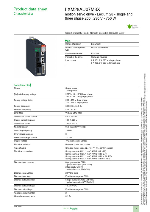
T h e i n f o r m a t i o n p r o v i d e d i n t h i s d o c u m e n t a t i o n c o n t a i n s g e n e r a l d e s c r i p t i o n s a n d /o r t e c h n i c a l c h a r a c t e r i s t i c s o f t h e p e r f o r m a n c e o f t h e p r o d u c t s c o n t a i n e d h e r e i n .T h i s d o c u m e n t a t i o n i s n o t i n t e n d e d a s a s u b s t i t u t e f o r a n d i s n o t t o b e u s e d f o r d e t e r m i n i n g s u i t a b i l i t y o r r e l i a b i l i t y o f t h e s e p r o d u c t s f o r s p e c i f i c u s e r a p p l i c a t i o n s .I t i s t h e d u t y o f a n y s u c h u s e r o r i n t e g r a t o r t o p e r f o r m t h e a p p r o p r i a t e a n d c o m p l e t e r i s k a n a l y s i s , e v a l u a t i o n a n d t e s t i n g o f t h e p r o d u c t s w i t h r e s p e c t t o t h e r e l e v a n t s p e c i f i c a p p l i c a t i o n o r u s e t h e r e o f .N e i t h e r S c h n e i d e r E l e c t r i c I n d u s t r i e s S A S n o r a n y o f i t s a f f i l i a t e s o r s u b s i d i a r i e s s h a l l b e r e s p o n s i b l e o r l i a b l e f o r m i s u s e o f t h e i n f o r m a t i o n c o n t a i n e d h e r e i n .Product data sheetCharacteristicsLXM28AU07M3Xmotion servo drive - Lexium 28 - single andthree phase 200...230 V - 750 WProduct availability: Stock - Normally stocked in distribution facilityMainRange of product Lexium 28Product or component typeMotion servo drive Device short name LXM28A Format of the drive Compact housingLine current6 A 181.8 % 220 V, single phase 6 A 160.6 % 220 V, three phaseComplementaryPhaseSingle phase Three phase[Us] rated supply voltage 220 V - 10...15 %)three phase 220 V - 20...15 %)single phase Supply voltage limits 200…255 V three phase 170…255 V single phase Supply frequency 50/60 Hz - 5...5 %Network frequency 47.5...63 Hz EMC filterWithout EMC filter Continuous output current 4.5 A 16 kHz Output current 3s peak 13.5 A 220 V Continuous power 750 W 220 VNominal power 0.75 kW 220 V 16 kHz Switching frequency 16 kHz Overvoltage category III Maximum leakage current 1.3 mAOutput voltage <= power supply voltage Electrical isolation Between power and controlType of cable Shielded motor cable 32…131 °F (0…55 °C)) copper Electrical connectionSpring terminal 0.82...1 mm², AWG 18 L1-L2)Spring terminal 0.82...1 mm², AWG 18 R, S, T)Spring terminal 0.82...1 mm², AWG 18 U, V, W, PE)Spring terminal 0.82...1 mm², AWG 18 PA/+, PBe)Discrete input number8 programmable CN1)1 pulse train input (PTI) CN1)2 fast capture CN1)1 safety function STO CN9)Discrete input voltage 24 V DC logicDiscrete input logic Positive or negative CN1)Discrete output number 5 logic output CN1)12...24 V DC 1 pulse train output (PTO) CN1)Discrete output voltage 12...24 V DCDiscrete output logic Positive or negative CN1)Analogue input number 2Absolute accuracy error0.1 %Analogue input type V_REF voltage analog input - 10...10 V 10 kOhm 14 bitsT_REF voltage analog inputControl signal type Servo motor encoder feedback CN2Protection type Against reverse polarity inputs signalAgainst short-circuits outputs signalOvercurrent motorOvervoltage motorUndervoltage motorOverheating motorOverload motorOverspeed motorSafety function STO (safe torque off), integratedSafety level SIL 2 IEC 61800-5-2 2007SIL 2 IEC 61508-1 2010PL d/category 3 EN/ISO 13849-1 2008SIL 2 EN/ISO 13849-1 2009/ACSIL 2 EN 60204-1 2006SIL 2 EN 60204-1 2009/A1SIL 2 EN 60204-1 2010/ACSIL 2 IEC 62061 2012Communication interface CANopen, integratedCANmotion, integratedConnector type RJ45 CN4)CANopen, CANmotionMethod of access SlaveTransmission rate250 kbit/s 328.08…820.21 ft (100…250 m) CANopen, CANmotion500 kbit/s 13.12…328.08 ft (4…100 m) CANopen, CANmotion1 Mbit/s 13.12 ft (4 m) CANopen, CANmotionNumber of addresses1…127 CANopen, CANmotionPhysical interface RS485 Modbus Serial line slaveStatus LED Charge 1 LED red)RUN 1 LED green)Error 1 LED red)Signalling function Servo status and fault codes five 7-segment display units Marking CSACULusCEType of cooling Integrated fanOperating position VerticalProduct compatibility Servo motor BCH2 5.12 in (130 mm), 1 500 WServo motor BCH2 3.15 in (80 mm), 2 750 WServo motor BCH2 5.12 in (130 mm), 1 600 WWidth 2.17 in (55 mm)Height 5.91 in (150 mm)Depth 5.75 in (146 mm)Net weight 2.20 lb(US) (1 kg)Output current 3s peak 213.5 A 220 VOutput current 3s peak 313.5 A 220 VEnvironmentElectromagnetic compatibility Conducted emission level 3category C3 EN/IEC 61800-3 Standards EN/IEC 61800-5-1Product certifications CECULusCSAIP degree of protection IP20Vibration resistance3M4 3 mm 9…200 Hz)IEC 60721-3-3Shock resistance10 gn, type I IEC 60721-3-3Relative humidity5…95 % without condensationAmbient air temperature for operation32…131 °F (0…55 °C)Ambient air temperature for storage-13…149 °F (-25…65 °C)Operating altitude<= 3280.84 ft (1000 m) without> 3280.84...6561.68 ft (> 1000...2000 m) 1 % per 100 mOrdering and shipping detailsCategory18262 - LEXIUM 23/28 SERVO DRIVESDiscount Schedule PC51GTIN00785901980469Package weight(Lbs) 1.32 kg (2.92 lb(US))Returnability YesCountry of origin CNOffer SustainabilitySustainable offer status Green Premium productCalifornia proposition 65WARNING: This product can expose you to chemicals including: Lead and leadcompounds which is known to the State of California to cause Carcinogen & Re-productive harm. For more information go to REACh Regulation REACh DeclarationREACh free of SVHC YesEU RoHS Directive Pro-active compliance (Product out of EU RoHS legal scope)EU RoHS Decla-rationMercury free YesRoHS exemption information YesChina RoHS Regulation China RoHS DeclarationEnvironmental Disclosure Product Environmental ProfileCircularity Profile End Of Life InformationWEEE The product must be disposed on European Union markets following specificwaste collection and never end up in rubbish bins.Dimensions DrawingsDimensions Dimensions of DriveMounting and ClearanceMounting ClearanceMounting Distances and Air Circulation。
Yaesu IC-7000 高功率多频带无线电说明书
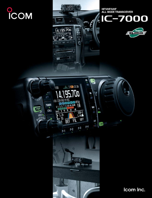
HF/VHF/UHFALL MODE TRANSCEIVERHF/VHF/UHF ALL MODE TRANSCEIVER35W output in 70cm bandHigh power MOS-FET amps supply 35W output power on 430/440MHz band as well as 100W on HF/50MHz bands and 50W on 144MHz. It pro-vides stable, high quality output with low IMD and low spurious emissions even during high duty cycle and extended operation.High stability crystal unitThe IC-7000 inco rpo rates a high-stability master o scillato r, pro viding 0.5ppm (–0°C to +50°C). A must for data mode operation.DDS (Direct digital synthesizer) circuitIcom’s original DDS (Direct digital synthesizer) circuit improves the C/N ratio, providing a clear, clean transmit signal in all bands.Compact, all in one packageThe IC-7000 sheds 20mm (0.79 in) of depth compared with the IC-706MKIIG. It’s compact body is easy for carrying outdoors or mobile operation.IF DSP — First in its classDigital IF fi lter, manual no tch fi lter, digital twin PBT and more. The lat-est digital features are incorporated in this compact radio from two DSP chips that deliver superior process-ing perfo rmance. Of co urse, tho se features work on all ham bands, from HF to the 70cm band.AGC loop performance controlled by DSPY ou will never experience AGC pumping from a signal filtered out by the DSP system. The digi-tal IF fi lter and manual notch fi lter are inside the AGC loop, so you will not encounter AGC block-ing. The AGC time constants are fl exibly adjust-able from slow, middle, fast (or AGC-off) for each operating mode.Digital IF fi ltersAll the fi lters you want at your fi ngertips! Y ou will never have to purchase “Optional” filters as the IC-7000 has adjustable digital filters. Y ou just dial in the width you wantand select whether you want a sharp or soft fi lter shape for SSB and CW modes. Then to pull-in the the weak ones, with a quickturn of the concentric twin PBT knobs, you can either narrow the IF passband, or shift the entire passband to eliminate the QRM.2-point MNF (Manual notch fi lter)Pull out the weak signals in crowded band condi-tions with Icom’s NEW two-point MNF (manualnotch fi lter). Apply 70 dB of rejection to two sig-nals at once! Notch width is adjustable – wide, medium, and narrow – and an auto-tuning notch fi lter is available, too.Digital noise reductionNoise reduction reduces background noise and improves signal-to-noise ratio. The noise reduction level is adjustable in 16 steps. It improves the readability of voice and data signals.Digital noise blankerThe noise blanker reduces pulse-type noise such as engine ignition and sparking. The NB level and width (blanking duration) are adjustable in 100 steps.AGC time constant setting Manual notch fi lterIF fi lter settingMOS FET P A unitsIcom original DDS circuitThe technical properties and advantages of IF DSP found in our leading base station models now offers its superior advantages on mobile HF, 50MHz 144MHz and 430/440 MHz bands.2.5 inch color TFT displayThe 2.5 inch color TFT display presents numbers and indicators in bright, concentrated colors for easy recognition. Y ou can choose from 3 back-ground colors and 2 font styles to suit your preference, in addition to a large operating frequency readout. And more, the Video output jack on the rear panel allows you to view a magnifi ed display on an external monitor*.* 3.5(d) mm monaural cable is required for connection.SSB transmit bandwidth adjustableThe SSB transmit bandwidth is selectable from 100, 200, 300, 500Hz atthe high-pass edge, and 2500, 2700, 2800, 2900Hz at the low-pass edgerespectively. 3 types of high and low combinations can be set in the quickset mode.2-mode band scopeThe band scope function lets you watch condi-tions aro und the band and visually assists infi nding other stations. In center mode the bandsco pe range is centered o n the receiving fre-quency (±10kHz to ±250kHz). In Fixed mode theband scope sweeps a fi xed range.Multi function meter and SWR graphic displayThe IC-7000 displays power level, SWR*, ALCand compression level of the speech compres-sor. The SWR graphic display* is useful for tuningantennas. The measuring step is selectable from10/50/100/500kHz steps and the number of mea-suring steps is adjustable from 3 to 13 steps. (* HF/50MHz band only)Other outstanding features• Front panel separation with optional 3.5m/5m separation cable • Selectablemain dial tension from heavy, light and click • RF speech compressor controlledby the DSP • CW full break-in • CW receive reverse • CW pitch adjustable •Tone squelch in FM mode • 503 memory channels • Built-in voice synthesizerannounces operating frequency, mode and signal strength • Duplex mode and au-tomatic repeater function • Transmit monitor • DTMF monitor • 1Hz tuning • VOX• CI-V interface • RIT/∂TX • RF/SQL knob • Large speaker • Auto TS function• Thermo control silent cooling fan • Noise squelch and S-meter squelch• Preamplifi er • Dial lock • 20dB attenuatorEight of the most-used radio func-tions such as NB, NR, MNF, andANF are co ntro lled by dedicatedfunction keys grouped around thedisplay for easy visibility. One quicktouch turns the function on and off.A lo nger to uch activates adjust-ment of the function’s setting.Digital voice recorder (DVR)Record your callsign, CQ, or other information in4 transmit playback memories with alphanumericlabels. A total of 90 seconds is available for thefour memories. A front panel REC control allowsyou to record incoming signals for up to 25 min-utes (99 channels)*. The DVR makes portablecontesting or mini-expeditions a breeze!* Up to 120 seconds per channelBuilt-in RTTY demodulatorThe RTTY demodulator and decoder are built-in.External units and PC are no longer required fordecoding. The twin peak audio fi lter reduces inter-fering signals overlapping the tones and the tuningindicator helps you zero-in with accurate tuning.Remote control microphone, HM-151The HM-151 has a 10-keypad for quick channel selection.The triple band stacking register memorizes the last threefrequencies and modes used on each band. Push the bandbutton once to three times to recall the channel setting. TheF-1 and F-2 buttons are programmable as shortcut menusof your often used functions.Key illuminationVoice RX memoryNegative type Color type Positive typeFixed mode band scopeRTTY decode screenMultimeter screen1-1-32, Kami-minami, Hirano-ku, Osaka 547-0003, Japan Phone: +81 (06) 6793 5302Fax: +81 (06) 6793 0013Count on us!www.icom.co.jp/worldPrinted in Japan2380 116th Avenue NE,Bellevue, WA 98004, U.S.A.Phone : +1 (425) 454-8155Fax : +1 (425) 454-1509E-mail :*********************URL : Unit 1 / 103 Garden Road,Clayton, VIC 3168 Australia Phone : +61 (03) 9549 7500Fax : +61 (03) 9549 7505 E-mail :**************.au URL : .auBlacksole House, Altira Park, Herne Bay, Kent, CT6 6GZ, U.K.Phone : +44 (01227) 741741Fax : +44 (01227) 741742E-mail :**************.ukURL : Zac de la Plaine,1 Rue Brindejonc des Moulinais, BP 45804, 31505 Toulouse Cedex 5, France Phone : +33 (5) 61 36 03 03Fax : +33 (5) 61 36 03 00E-mail :********************URL : Ctra. Rubi, No. 88 "Edificio Can Castanyer" Bajos A 08174, Sant Cugat del Valles, Barcelona, SpainPhone : +34 (93) 590 26 70Fax : +34 (93) 589 04 46E-mail :******************URL : 146A Harris Road, East Tamaki,Auckland, New Zealand Phone : +64 (09) 274 4062Fax : +64 (09) 274 4708E-mail :*****************.nz URL : Glenwood Centre #150-6165 Highway 17,Delta, B.C., V4K 5B8, Canada Phone: +1 (604) 952-4266Fax : +1 (604) 952-0090E-mail :*******************URL: Y our local distributor/dealer:6F No. 68, Sec. 1 Cheng-Teh Road, T aipei, Taiwan, R.O.C.Phone: +886 (02) 2559 1899Fax : +886 (02) 2559 1874E-mail :*******************URL : 81-850 Sopot, ul. 3 Maja 54, Poland Phone : +48 (58) 550 7135Fax : +48 (58) 551 0484E-mail :*************************.pl URL : .plCommunication Equipment Auf der Krautweide 2465812 Bad Soden am Taunus, Germany Phone : +49 (6196) 76685-0Fax : +49 (6196) 76685-50E-mail :*******************URL : HF/VHF/UHF ALL MODE TRANSCEIVER• C T-17 C I-V LEVEL CONVERTERFo r remo te transceiver co ntro l using a PC with an RS-232C.• R S-BA1 I P REMOTE CONTROL SOFTWAREFor IP remote transceiver control from a PC. (Not guaranteed)• Frequency coverage (unit: MHz)*1 :Receive 0.030– 199.999*2 400.000–470.000*2 Transmit 1.800– 1.999 3.500– 3.9995.255– 5.405*2 7.000–7.300 10.100– 10.150 14.000– 14.350 18.068– 18.168 21.000– 21.450 24.890– 24.990 28.000– 29.700 50.000– 54.000 144.000– 148.000430.000– 450.000*1 Showing USA version, frequency coverage depends on version.*2 Some frequency ranges are not guaranteed.• Mode: U SB, LSB, CW, RTTY , AM, FM,WFM (Rx only)• Number of memory Ch. : 503 (495 regular, 6 scan edges and 2 call)• Antenna connector : S O-239×2 (fo r HF/50MHz and 144/430/440MHz bands; 50Ω)• T emperature range : –10˚C to +60˚C; +14˚F to +140˚F • Frequency stability : L ess than ±0.5ppm(0°C to +50°C; +32°F to +122°F)• Power supply requirement : 13.8V DC ±15% • P ower consumption : Tx Max. power 22.0A (approx.) Rx S tandby 1.3AMax. audio 1.6A• D imensions (W×H×D): 167×58×180 mm;(Projections not included) 6.57×2.28×7.09 in• Weight (approx.): 2.3kg; 5.1lb • Modulation system :S SB Digital P .S.N. modulation AM Digital low power modulation FM Digital phase modulation • Spurious emissions : L ess than –50dB (HF bands)Less than –60dB (50MHz band*)Less than –60dB (144/440MHz bands)(* Less than –63dB for EUR versions)• Carrier suppression : More than 50dB • Unwanted sideband suppression: More than 50dB• Microphone connector : 8-pin modular jack (600Ω)• Intermediate frequencies :S SB, CW, RTTY , AM, FM 124.487MHz, 455kHz, 16.15kHz WFM 134.732MHz, 10.70MHz SSB/CW, AM : 10dB S/N, FM, WFM : 12dB SINAD• Squelch sensitivity (Pre-amp: ON, threshold):SSB Less than 5.6μV FM Less than 0.3μV • Selectivity (representative value): S SB More than 2.4kHz/–6dB(BW: 2.4kHz, sharp) Less than 3.6kHz/–60dB C W More than 500Hz/–6dB(BW: 500Hz, sharp) Less than 900Hz/–60dBRTTY(BW: 350Hz) M ore than 360Hz/–6dB Less than 650Hz/–60dBAM(BW: 6kHz) M ore than 6.0kHz/–6dB Less than 15.0kHz/–60dBFM(BW: 15kHz) M ore than 12.0kHz/–6dB Less than 20.0kHz/–60dB• S purious and image : More than 70dB (HF/50MHz bands)rejection ratio More than 65dB (144/440MHz bands)(except 1/2 IF through on 50MHz, IF through on 144MHz)• AF output power : M ore than 2.0W at 10% distortion (at 13.8V DC)with an 8Ω load• EXT SP connector : 2-conductor 3.5 (d) mm (1⁄8ʺ)/8ΩApplicable U.S. Military Specifi cationsSPECIFICATIONSRECEIVERSupplied accessories:• Hand microphone, HM-151 • Microphone hanger • Electronic keyer plug • RTTY key plug • DC power cable • ACC cable (13-pin) • Spare fuses• O PC-599 CABLE ADAPTERCo nverts 13-pin ACC co nnecto r to 7-pin + 8-pin ACC connector forconnection with IC-PW1/EURO.• O PC-742 ACC 13 PIN CABLE ADAPTERRequired when using both AT -180 and a 2 m or 70 cm linear amplifi er.• S EP ARA TION CABLES OPC-1443: 3.5m (11ft)OPC-1444: 5m (16ft)• O PC-589 MODULAR 8-PINCABLE ADAPTER• O PC-598 ACC 13 PIN LONG CABLE FOR A T -180 (7m; 23ft)• M B-106 CARRYING HANDLEOPTIONS• M B-105A MOBILE MOUNT -ING BRACKETFo r mo unting the detached fro nt panel.• M BF-1 MOUNTING BASESuctio n cup mo unting base fo r mo unting the detached fro nt panel. The MB-105A is required.• A H-2b ANTENNA ELEMENTFor mobile operation with the AH-4. All bands between 7–54MHz can be matched.• A H-4 HF+50MHz AUTO-MA TIC ANTENNA TUNERCo vers 3.5–54MHz with a 7m • A T -180 HF+50MHz AUTO-MA TIC ANTENNA TUNERStyle and size are matched to the IC-PW1/IC-PW1EUROHF+50MHz 1kWHF LINEAR AMPLIFIER• H M-151 REMOTE-CONTROL MICROPHONESame as supplied. For exclusive use with IC-7000 only.• S P-10 EXTERNAL SPEAKERHeavy duty speaker fo r mo bile use.• PS-126 DC POWER SUPPL Y13.8V DC, 25A max. with 4-pin type connector.READ ALL INSTRUCTIONS carefully and completely before using the transceiver.All stated specifi cations are subject to change without notice or obligation.Some options may not be available in some countries. Please ask your dealer for details.• S M-30 DESKTOP MICROPHONEElectret microphone.(An optional OPC-589 is required.)SM-20 also can be used with OPC-589.• S M-50 DESKTOP MICROPHONEDynamic microphone.(An optional OPC-589 is required.)• M B-120 MOUNTING BASEFo r mo unting the detached fro nt panel in a vehicle. The MB-105A is required.05ES011K* © 2005–2012 Icom Inc.• M B-62 MOBILE MOUNTING BRACKETFo r mo unting the IC-7000 main unit or the A T -180.Covers all HF and 50MHz bands, provides clean, stable 1kW output.Automatic antenna tuner and compact detachable controller are standard. 2 exciter inputs are available. (An optional OPC-599 is required.)。
KYN28中英文对照说明书

KYN28(GZS1)-12型户内交流金属铠装抽出式开关设备KYN28 (GZS1) -12Indoor AC metal-clad withdrawable switchgear许继电气股份有限公司XJ Electric Co., Ltd.KYN28(GZS1)-12型户内交流金属铠装抽出式开关设备KYN28 (GZS1) -12Indoor AC metal-clad withdrawable switchgearGZS1 —国内领先的新型开关设备—开关设备断路器采用中置手车式,额定电流从630A~3150A,短路开断电流最大可达50kA,是传统12kV等级开关设备的更新换代产品。
GZS1 - New switchgear with advanced technologies in China- Switchgear circuit breaker is the centrally-installed truck type with rated current from 630A to 3150A and short-circuit breaking current up to 50kA. It is the substitute product of traditional 12kV switchgear.GZS1 —安全可靠的开关设备—完全金属铠装及全封闭结构—采用均衡电场的措施,具有较高的绝缘性能—低压室及各高压隔室之间各自独立隔开—快速合闸接地开关用于接地和人工短路—所有设备的操作,包括断路器的分合闸,断路器手车的推入或移出以及接地开关的分合闸操作等,在门板关闭状态下进行—具有可靠的“五防”闭锁装置,能有效的防止误操作—透过门板的观察窗,可方便的查看断路器分合闸状态及手车位置、机构储能状态、接地开关分合位置以及电缆头的连接情况GZS1 - Safe and reliable switching equipment- Full metal-clad and fully enclosed structure- Take measures for electric field equalization; with higher insulating performance- Independent separation between low voltage compartments and between all high voltage compartments- Quick closing grounding switch is used for grounding and artificial short-circuit- All operations of the equipment (including opening and closing of the circuit breaker, movement of circuit breaker truck, and opening and closing of the grounding switch) can be performed when the doors are closed.- Reliable "five-prevention" locking function; provide effective avoidance of misoperation- Through observation window, you may easily find the circuit breaker ON/OFF status, the position of truck, the mechanism energy storage state, the ON/OFF position of the grounding switch and the connection conditions of the cable head.GZS1 —实用性强的开关设备—壳体密封性能好,防护等级达IP4X—真空断路器手车为免维修型—手车互换性极好GZS1 - Practical switchgear- E nclosure has good sealing performance with protection degree of IP4X- Vacuum circuit breaker truck is maintenance-free type- Interchangeability of truck is excellentGZS1 —适应性广的开关设备—电缆室有充裕的空间,可连接多根电缆,安装、维修方便—柜体可靠墙安装,减少占地面积GZS1 - Greatly adaptable switchgear- Cable compartment has plenty of space where many cables can be connected and installation and maintenance can be easily carried out.- The cabinet can be installed against a wall. Floor space taking up can be reduced. GZS1 —具有先进技术水平的智能型开关设备—开关设备内部采用先进的微电子及微电脑技术,使其进一步智能化—可配用多种智能保护装置,实现设备和线路的综合保护功能,并具有自动监测、自动诊断等功能GZS1 - Intelligent switchgear with advanced technical level- The switchgear equipped with advanced microelectronic and microcomputer technologies becomes more intelligent.- It can be equipped with a variety of intelligent protection devices, providing comprehensive protection of equipment and lines and functions of "automatic monitoring" and "automatic diagnosis".目录Contents1 总则 (4)1 General (4)2 产品型号及含义 (5)2 Model and Definition of product (5)3 技术参数(见表1) (6)3 Technical parameters (see Table 1) (6)4 外形尺寸(见图1及表2) (6)4 Dimensions (See figure 1 and table 2) (7)5 开关设备结构简介 (10)5 Overview of switchgear structure (8)6 防污秽措施 (13)6. Anti-contamination measures (14)7. 真空断路器简介 (14)7 Overview of vacuum circuit breaker (14)8 开关设备的安装 (34)8. Installation of switchgear (34)9 开关设备的接地装置 (34)9 Grounding device of switching equipment (34)10 运输与存放 (34)10 Transportation and Storage (34)11 产品配套文件 (35)11. Supporting documents for products (35)12 其它 (35)12. Others (35)铭谢惠顾请阁下对照此说明书使用本产品多谢合作T h a n k s f o r y o u r p u r c h a s i n g!P l e a s e o p e r a t e t h i s p r o d u c t a c c o r d i n g t ot h i s M a n u a l.T h a n k y o u f o r y o u rc o o p e r a t i o n!1 总则1 General1.1 概述由许继电气股份有限公司生产的KYN28(GZS1)-12型户内交流金属铠装抽出式开关设备(以下简称开关设备),系3~12千伏三相交流50Hz单母线及单母线分段系统的成套配电装置,主要用于发电厂、中小型发电机送电、工矿企事业配电以及电业系统的二次变电所的受电、送电及大型高压电动机启动等,实现控制、保护、检测之目的。
EPM7128SLC84-6中文资料(Altera)中文数据手册「EasyDatasheet - 矽搜」
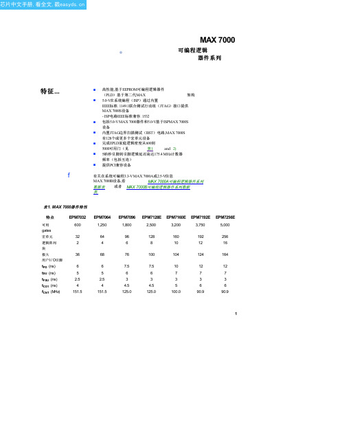
表 4. MAX 7000器件特性
特点
EPM7032 EPM7064 EPM7096
All MAX 7000E
设备
All MAX 7000S
设备
通过JTAG接口,ISP
JTAG BST电路
开漏输出选项 快速输入寄存器 全球六大输出使 两个全局时钟 摆率控制 多电压接口 可编程寄存器 并行扩展 共享扩展 省电模式 安全位 提供PCI兼容设备
表 5. MAX 7000最大用户 I / O引脚
器
注(1)
4444446884- 100- 100Pin Pin Pin Pin Pin Pin Pin PLCC PQFP TQFP PLCC PLCC PQFP TQFP
36 36 36 36 36 36 36 36 36
160Pin PQFP
160Pin PGA
192Pin PGA
208Pin PQFP
208Pin RQFP
EPM7032 EPM7032S EPM7064 EPM7064S EPM7096 EPM7128E EPM7128S EPM7160E EPM7160S EPM7192E EPM7192S EPM7256E EPM7256S
注意事项:
EPM7064
1,250 64 4 68 6 5 2.5 4 151.5
EPM7096
1,800 96 6 76 7.5 6 3 4.5 125.0
EPM7128E
2,500 128 8 100 7.5 6 3 4.5 125.0
EPM7160E
3,200 160 10 104 10 7 3 5 100.0
最大7000E设备,包括EPM7128E,EPM7160E, EPM7192E和EPM7256E设备,有几个增强功能:附加全局时钟,额 外输出使能控制,增强互连资源,快速输入寄存器和一个可编程转换 速率.
Lumaxcape Quadralux Q6产品手册说明书

PRODUCT GUIDEArchitectural & Facade LightingDesigned toilluminate and inspire.Transform architectural masterpieces into dazzling displays of performance art withbest-in-class lighting solutions from Lumascape. Each future-ready luminaire deliverstop performance in every application. For high-speed digital dimming and color-changingcapabilities, add PowerSync™ technology. Learn more at .Quadralux Q61Product availability and configuration may vary for different markets.* Indication of performance for 4,000 KFACADEDesigned to Perform and ExciteUVGuard™ Technology. The linear offers best-in-class photometric performance,with over 1,200 lm from a 4' (1.2 m) RGBW, and over 2,400 lm from a whiteluminaire. With Vestalux V2 luminaires on your project, imagination is the only limit!Rialto Towers3Product availability and configuration may vary for different markets.* Indication of performance for 4,000 KVestalux V1 LS9015Vestalux V2 LS9016Faisca F6 LS9260485 lm/ft *, 7 W/ft598 lm/ft *, 7 W/ft1,870 lm *, 20 WSingle Colour RGBA | RGBW Tunable WhiteAvailable in 1 ft, 2 ft, 3 ft, 4 ftSingle Colour RGBA | RGBW Tunable WhiteAvailable in 1 ft, 2 ft, 3 ft, 4 ftSingle ColourRGBA | RGBWTunable Whitep wer sync ®4p wer sync ®4p wer sync ®4DIRECT VIEWTransform your space through light with Lumascape’s full range of facade, direct view and in-ground linear solutions. From performance graze, to direct view and cove applications, Lumascape has you covered. With the command and flexibility of PowerSync™ technology, these best-in-class performance products add significant capability to the Lumascape product portfolio. Find your perfect linear solution at Complete Linear SolutionUnleash your creativity with theComplete Linear SolutionProduct availability and configuration may vary for different markets.CE VersionUL Version Centria C1 LS2012FOUNDATION5 * Indication of performance for 4,000 KIlluminate with perfection, from the ground up Eastmark Great Park7Product availability and configuration may vary for different markets.* Indication of performance for 4,000 KIN-GROUNDp wer syncIllumination that’salways one step aheadRobust, easy-to-install wall-mounted luminaires from Lumascape are expertly engineered to increase pedestrian safety, define spaces, and enhance architectural elements while delivering long-lasting performance in busy outdoor environments. Choose from a variety of high-output luminaires in a range of styles to seamlessly integrate wall lighting into classic and contemporary settings.Wall-Mounted LuminairesWALL-MOUNTOmnio OM2 LS411COB1,490 lm*, 25.6 WSingle ColourGROUND MOUNTUL VersionCE VersionCentria C1 LS20102,560 lm*, 25 WVE4 LS9404LEDVedita VE7 LS9407LEDDOWNLIGHTSBOLLARDS & PATHWAYRise RS8 LS23881,520 lm *, 25 WSingle ColourNero NE1 LS333ANS-2LED Tristar TR1 LS265LED Vedita VE5 LS9405LED 875 lm*, 9 W2,160 lm*, 32 W210 lm*, 2.8 W Single Colour RGB Single Colour RGB Single ColourRequires pre-installation niche UNDERWATERIntelligent Electronics For LED Luminaires/technologyp wer sync ®4IO I O I I O O O I O I O O I I What is PowerSync ®?»PowerSync was born from an industry need for simplified, contractor friendly installation without compromising dimming quality.»PowerSync supports industry standard protocols:0-10V, ELV and DMX/RDM.»High resolution dimming to 0.1%.»Installation of PowerSync requires only standard wiring methods and materials.»PowerSync uses a single extra conductor to carry data – less copper, fewer connectons vs. other manufacturers using standard control methods.»Consistent dimming performance, wiring and installation across all PowerSync luminaires,regardless of the incoming signal.Data Injector PS4 LS6540LV Data Injector PS4 LS6550DXM Controller LS69501024 Channelp wer sync ®4p wer sync ®4POWER & CONTROLSGLOBAL DISTRIBUTION NETWORKO M 186-220513ARCHITECTURAL & FACADE LIGHTING Learn more. Visit AUSTRALIA / OCEANIABrisbane Technology Park 77 Brandl StreetEight Mile Plains QLD 4113 Australia P: +61 7 3854 5000F: +61 7 3854 5001E:*******************MIDDLE EASTDubai World CentreBuilding Block C, Office #432Dubai, United Arab Emirates P: +971 4 887 9951 F: +971 4 887 9601E:********************NORTH AMERICA1940 Diamond StreetSan Marcos, California 92078United States of America P: +1 650 595 5862E:******************ASIA20 West Building, No 377 Wuyi Road Wujin Hi-Tech ZoneChangzhou, Jiangsu, China P: +86 519 8919 2555F: +86 519 8919 1053E:************************EUROPEVia Molise, 6,37138 Verona, Italy P: +39 045 810 3615E:*********************UNITED KINGDOME:*********************。
QUICKIE Q700M 高性能电动椅子说明书

THE ULTIMATEEXPERIENCEQUICKIE®delivers the world’s most comprehensiverange of innovative, technically advanced powerchairs, created specifically for your clinicaland lifestyle needs. 2Resulting from years of experience, the QUICKIE®Q700™Moffers the highest performance and technology, providingyou with The Ultimate Experience!HigH-pErformancE BasEAdvanced mid-wheel drive technology gets you where you want to go.SpiderTrac®2.0 suspension and our patented anti-pitch system provideexcellent outdoor performance and smooth curb climbing.inTElligEnT sEaTingMirroring your body’s natural positions, the SEDEO®ERGO’s™BiometricRepositioning helps you maintain contact with your footplate, headrest or chincontrols during seat transitions. Access six programmable seat positions atthe touch of a button.innovaTivE conTrolsSeamlessly connect with your environment, your smart phone, computerand other electronics with a choice of industry-leading, intuitive and easy-to-operate controls, including infrared and BLUETOOTH®.DisTingUisHED sTylEThe Q700 M has a streamlined, minimalistic design contrasted with sleek,black bodywork and striking color inlays. Every detail from the upholsterydown to the wheels has been designed to turn heads.3MID-WHEEL DRIVEPERFORMANCE,EVOLVEDTRAVEL WITH CONFIDENCE4sTay on Track wiTH sUrETrac®The optional SureTrac system automatically detects and corrects the smallest deviation from your input direction. By providing a pinpoint accurate drive, it will reduce the number of physical or cognitive actions required to keep you on track, making for a less demanding drive (especially if using specialty controls).INDOOR MANEUVERABILITYOUTDOORPERFORMANCETurning on its own axis, enjoy intuitive driving and excellent maneuverability in tight compact spaces with this narrow 25" base and a 23.5" turning radius. Also, easily roll under tables and access Wheelchair Adaptive Vehicles (WAVs) with a low minimum seat height of just 17".5SEDEO ®ERGO ™INTELLIGENT SEATINGEASY TRANSFERUPHOLSTERY OPTIONSn n n 6aDjUsTaBlE To fiT yoUThe premium headrest (1) can be easily adjusted or removed. All seat widths and depths (2) are infinitely adjustable with just one tool. Also, the seat and backrest width (3) can be adjusted independently of each other. Even the armrest height and angle (4) are simple to adjust.BiomETric rEposiTioningMoving out of a reclined position often requires use of the tilt function to regain your proper seated posture. With the patented Biometric Repositioning,when you move from reclined to seated, the SEDEO ERGO will first pass through an intermediary tilted position, using gravity to realign your pelvis in one smooth, effortless motion.anTi-sHEar BackrEsTTransitioning in and out of recline doesn’t need to be uncomfortable. The SEDEO ERGO’s power recline is supported by 7" of anti-shear to better maintain the positioning of the headrest, and even chin control,during recline.prEssUrE rEliEf rEminDErsPressure relief reminders tell you when it’s time to change position. A log can also be kept for clinicians to review.programmaBlE mEmory sEaTingThe SEDEO ERGO has 6 uniquely customizable seating positions that can be programmed to any position you desire. Whether you want to lie down, cook, or watch TV – every position can be completely customized to you.fooTplaTE opTionsChoose from 2 sizes of footplates to meet your unique needs, and select the optional ability to lower the footplate all the way to the ground, making transfers easier.12347QUICKIE Q700 MSEDEO ERGO SEATING SYSTEMLive life on-the-go with the Q700 M SEDEO ERGO. Combining all the benefits of the SEDEO ERGO seating system with the ability to travel at your pace when elevated with C-Me®.8mEmory posiTionsElEvaTE anD DrivE wiTH c-mE ®No more waiting around or driving at reduced speed when elevated. C-Me en-ables you to elevate up to 12" while traveling up to 3 mph! (Weight limitations may apply.*) You can lift or descend at the touch of a button with no need to stop while transitioning. Just rise-up and go at the same time!SEATED TRANSFER FEET ABOVE HEART SUPINEC-MEPRESSURE RELIEF9With memory seating, you can save up to six programmable positions and transition with the simple press of a button.JAY ®& WHITMYER ®SEATING OPTIONSA wide range of JAY cushions and backs and Whitmyer headrests are available with the SEDEO ERGO seating system.jay ®cUsHions & BacksDesigned for pelvic stability, skin protection and comfort,JAY cushions and backs are low maintenance, highly customizable and available in a wide variety to meet your needs.wHiTmyEr ®HEaDrEsTsPurposefully engineered to address a range of needs from basic support to multiple-point control, Whitmyer headrests have five mounting options and a variety of pad shapes and sizes for superior head positioning and comfort.JAY Union ®Contoured Cradle w/LINX 2PLUSH w/AXYS PLUSH w/Cobra Adjust-A-PLUSH w/LINXJAY J3®BackJAY Fusion ®10SWITCH-IT ™REMOTE SEATING APP The Remote Seating app plays an important role in pressure management.With the app, you can self-monitor your pressure relief progress andsecurely share the data with your caregiver network. The app trackskey seating positions such as tilt, recline and leg elevation, as well asthe duration of these positions.11TRACK. ACT. THRIVE.With the one-touch app, there’s no need to log into a cumbersomeportal, just connect to your chair. The data stays with your chair and iseasily accessible via your phone or tablet. You can also email reportsinstantly to your choice of clinicians and doctors.DATA. WHEN YOU WANT IT. WHERE YOU WANT IT.TAKE CHARGE OF YOUR SKIN HEALTH.n Secure datan Easy accessn Bluetooth ®connectionn Live progress reportsn View data directly on your devicen Assists in pressure relief plansn Pressure relief alert remindersn Compatible with Android ™and Apple ®iOS(Refer to owner’s manual for compatible versions.)Android is a trademark of Google LLC.CONTROL AT YOUR FINGERTIPSBe the master of your environment with the Q700 M Series and itsadvanced controller technology. Not only can you control yourQ700 M the way you want, but also your phone, computer, tabletand all Bluetooth ®devices, including Android ™and Apple ®iOS devices.connEcTSeamlessly take control of your environment using the integrated infrared functionality.Use your joystick like a remote control for your TV and select home entertainmentsystems.BlUETooTH ®wirElEss TEcHnologyControl your phone, computer, tablet and all Bluetooth ®devices with this usefuloption. Connect and control up to four devices. Compatible with Android ™andApple ®iOS devices.QUickiE paTEnTED assignaBlE BUTTonsChange the function of any button on your joystick to any command youdesire, thanks to QUICKIE assignable buttons. You can also assign a second(long press) function to buttons, giving you quicker, simpler and smootheraccess to functions you commonly use without having to use your joystick.R-NET ADVANCED JOYSTICKEvery Q700 M Series comes with the superior R-net Advanced Joystick.A large, easy-to-read display – largest in the market – and simple tocontrol paddle switches allow for intuitive operation.12SWITCH-IT ™INNOVATIVE CONTROLS alTErnaTivE DrivE conTrolscTrl+5®If driving with a traditional joystick is not the best option, alternativedrive controls allow you to fully experience your chair’s drivingcapabilities and benefits.Conveniently access five seating functions with the Ctrl+5 – a perfectcombination with Memory Seating. It allows you to go straight to thefunction you need at the touch of a button.MICROGUIDE Light-touch proportional control Available in push-button or toggleVERSAGUIDE Compact proportional control DUAL PRO ®Truly proportional head array for intuitive drivingLINK-IT MOUNTING SYSTEMUsing a combination of available modules and rods, create endless combinations.It’s easy to position and ensures your wheelchair maintains its sleek look. Whetherit’s an extra controller on the armrest, a push button on the backrest or a switch onthe headrest, just link-it.Need to use additional switches or specialty controls? No problem!Easily connect them using the universal Link-It Mounting System.14DISTINGUISHED STYLEWith the Q700 M series, we’ve taken style to the next level. With a matte black chassis finish, hidden wiring and premium upholstery, the Q700 M has a sleek and contemporary design.The Q700 M also comes with a choice of six contemporary color inlays to perfectly complement its striking matte black bodywork. Fancy a change? Simply replace the color inlays. Styling your powered wheelchair has never been so simple.*C-Me at 3 mph has a max. user weight of 250 lbs.。
HP ScanJet Enterprise Flow 7000 s3 (L2757A) 用户手册说明

Data sheet HP ScanJet Enterprise Flow 7000 s3(L2757A)Improve your paper process – with speed and controlGive your office high-volume scanning performance. Easily download software—including Kofax VRS 5.1Professional —that helps you save time and capture con dently. Achieve scan speeds up to 75 ppm/150ipm.Recommended for 7,500 pages per day.Fast, smooth scanning – even unattendedCapture entire documents with one-pass duplex scanning up to 150 ipm black-and-white and colour.Free up space for work. This HP ScanJet is small and slim – a modern design perfect for the desktop.Capture a wide range of documents—even stacks of mixed media sizes and types—with HP EveryPage.Load up to 80 pages into the automatic document feeder for fast, unattended scanning.Peak work ow performance. Smarter scanning.Identify new devices and gain insight into scanning with HP Web Jetadmin remote discovery and monitoring.Simplify the way you scan A3-size documents – no need for a carrier sheet.Scan images directly into applications with included and full-featured 32-bit and 64-bit TWAIN and ISIS®.Easily transfer scans into editable text, encrypted PDF les, and more le types, using built-in OCR and zonal OCR.Professional-grade scanning that helps save time Save time and simplify complex scan jobs with HP Scan Premium.Create one-button scan settings for recurring tasks, and make selections using the LCD control panel.FootnotesScan speed measured at 300 dpi (black-and-white, grayscale, and color). Actual processing speeds may vary depending on scan resolution, computer performance, and application software. HP EveryPage is referred to as HP Precision Feed on HP ScanJet devices introduced prior to May 2013.HP Web Jetadmin is available for download at no additional charge at /go/webjetadmin. Support for the HP ScanJet Enterprise Flow 7000 s3 available mid-November , 2016. Expected availability for Kofax VRS 5.1 Professional is November 1, 2016412231234Data sheet | HP ScanJet Enterprise Flow 7000 s3Accessories and services AccessoriesL2756A HP ScanJet 5000 s4/7000 s3 Roller Replacement Kit Service and Support U1Q59E HP 3 years Next business day Exchange ScanJet 7000s2/7000s2 Flow Service U5X49E HP 4 years Next business day Exchange ScanJet 7000s2/7000s2 Flow Service U5X50E HP 5 years Next business day Exchange ScanJet 7000s2/7000s2 Flow Service U5X46PE HP 1 year Post Warranty Next business day Exchange ScanJet 7000s2/7000s2 Flow Service U1Q60E HP 3 years Next business day Onsite Exchange ScanJet 7000s2/7000s2 Flow Service U5X51E HP 4 years Next business day Onsite Exchange ScanJet 7000s2/7000s2 Flow Service U1Q62E HP 5 years Next business day Onsite Exchange ScanJet 7000s2/7000s2 Flow Service U5X47PE HP 1 year Post Warranty Next business day Onsite Exchange ScanJet 7000s2/7000s2 Flow Service U1Q61E HP 3 years Standard Exchange ScanJet 7000s2/7000s2 Flow Service U5X48PE HP 1 year Post Warranty Standard Exchange ScanJet 7000s2/7000s2 Flow Service U5X52E HP 3 years Return ScanJet 7000s2/7000s2 Flow Service (U1Q59E, U5X49E, U5X50E, U5X46PE: all except Baltics, RSA, Turkey. U1Q60E, U5X51E, U1Q62E, U5X47PE: France, Spain, Portugal, Austria, Switzerland, Finland, Norway,Sweden, Belgium, Netherlands, Poland, Russia, Greece. U1Q61E, U5X48PE: Baltics, RSA. U5X52E: Turkey)Technical speci cationsControl panel2-line 16 character per line LCD display, Simplex button, Duplex button, Cancel button, Power button with a LED and Tool button Scanner speci cationsScanner type Sheetfed; Scan technology: CMOS CIS; Scan input modes: Two scan modes (simplex/duplex) on front-panel for HP Scan Premium in Win OS and third parties applications via TWAIN, ISIS and WIA; Twain version: Windows: 32-bit and 64-bit TWAIN version 2.1; Mac: n/a; Colour scanning: Yes; Output resolution dpi settings: 75; 150; 200; 240; 300; 400; 500; 600; 1200 ppi; Image scaling or enlargement range: Will not perform any arbitrary scaling Scan SizeADF: Maximum 216 x 3100 mm; Minimum 50.8 x 50.8 mm Scan speed Up to 75 ppm/150 ipm (black & white, 300ppi)Scan resolution Optical Up to 600 dpi (colour and monochrome, sheet-feed); Hardware: Up to 600 dpi (colour and monochrome, sheet-feed)Scan le format For text & images: ePub 3.0, HTML 4.0, Excel le format (*.xls, *.xlsx), PowerPoint le format (*.pptx), Word (*.docx), WordPerfect (*.wpd), searchable PDF , JPEG, PNG, BMP , TIFF , Text (.txt), Rich Text (rtf),XML and XPSScanner advanced features Auto exposure, Auto threshold, Auto detect color , Background smooth/removal, Remove Noise, Auto detect size, Straighten content, Enhance content, Multi-streaming, Auto feed, Multi-feed detection sensor , Auto orient, Multi-color dropout, Channel color dropout, Edge erase, Resize page, Delete blank page, Merge pages, Hole ll, Digital stamps, Metadata capture, PDF permissions, Document separation (Blank page, Barcode)Grayscale levels/Bit depth 256/24-bits external; 48-bits internalDuty cycle Recommended for 7,500 pages per dayAuto document feeder capacity 80 sheets Connectivity Standard Hi-Speed USB 2.0 and USB 3.0MemoryStandard 512 MB External I/O ports1 x USB 3.0 and 1 x USB 2.0 portMedia handlingMedia types Cut sheet paper , printed paper (laser and ink), pre-punched paper , bank checks, business cards, freight bills, carbonless forms, plastic carrier sheets for easily damaged documents, previously stapled media with staple removed, plastic cards (up to 1.24 mm)Media size (ADF)ISO A4: 210 x 297 mm; ISO A5: 148 x 210 mm; ISO A6: 105 x 148 mm; ISO A7: 74 x 104 mm; ISO A8: 52 x 74 mm; ISO B5: 176 x 250 mm; JIS B5: 182 x 257 mmMedia weight (ADF)40 to 413 g/m²Compatible operating systems OS X El Capitan 10.11, Microsoft® Windows®10, 8, 7, XPMinimum system requirements PC: Microsoft® Windows® 10, 8.1, 8, 7, XP: 32/64-bit, 2 GB available hard disk space, CD-ROM/DVD drive or Internet connection, USB port, Microsoft® Internet Explorer; Windows Vista®: 32-bit only, 2 GB available hard disk space, CD-ROM/DVD drive or Internet connection, USB port, Microsoft® Internet Explorer 8Software included HP WIA scan driver , HP TWAIN scan driver (32-bit and 64-bit), HP Scan Premium, HP Scanner Tools Utility, EMC ISIS driver , Kofax VRS ProScan Server Speci cations Security management Power button to on/off deviceDimensions and weight Product dimensions (W x D x H)Minimum : 310 x 198 x 190 mm; Maximum: 342 x310 x 319 mmPackage dimensions (W x D x H)397 x 248 x 303 mmProduct weight 3.8 kgPackage weight 5.4 kgOperating environment Temperature: 10 to 35ºC Humidity: 15 to 80% RH (non-condensing)Storage Temperature: -40 to 60ºCPower Requirements: Input Voltage: 90 to 264 VAC, 50/60 Hz; Consumption: 6.7 watts (ready), 0.9 watts (sleep), 0.1 watts (off), 0.1 watts (auto-off); ENERGY STAR: YesCerti cations IEC 60950-1:2005+A1+A11+A12 and all applicable amendments; EN 60950-1:2006+A11+A1+A12+A2; EAC safety; European Union CE; Kenya PVOC; Kuwait TER; Nigeria SON; Saudi Arabia SASO; South Africa NRCS; Ukraine safety approval Electromagnetic compatibility: Class B Emissions; CISPR 22:2008 (International); European Union EMC Directive 2004/108/EC, EN 55022:2010 (CE mark); EAC EMC Certi cate; Ukraine EMC approval; EN 61000-3-2:2014 (harmonics); EN 61000-3-3:2013 ( icker); Immunity CISPR 24:2010, EN 50024:2010 ENERGY STAR® 3.0 certi edWhat's in the box L2757A HP ScanJet Enterprise Flow 7000 s3 Sheet feed Scanner; Installation guide, Support yer , Warranty guide; Power cord; USB cable; Power AdapterWarrantyOne-year bench commercial warranty whole unit replacement, phone and Web support included. Warranty may vary by country as required by law. Go to /support to learn about HP service and support options in your region.Technical speci cations disclaimersActual speeds may vary depending on scan resolution, connectivity type, computer performance and application software. With input and output trays folded and covers closed.Power requirements are based on the country/region where the scanner is sold. Do not convert operating voltages. This will damage the scanner and void the product warranty.© Copyright 2023 HP Development Company, L.P. The information contained herein is subject to change without notice. The only warranties for HP products and services are set forth in the express warranty statements accompanying such products and services. Nothing herein should be construed as constituting an additional warranty. HP shall not be liable for technical or editorial errors or omissions contained herein.ae-en August 2023123123。
Philipseries 7000 Nano 电离电гла Id玛洁象bled li 双面电警铃 W

S7887/58shave, advanced skin protectionwith SkinIQ TechnologyThe Philips Series 7000 glides smoothly over your skin, while cutting each hairclose - even on 3 day beards. Equipped with advanced SkinIQ technology, theshaver senses, adapts and guides on the correct motion, for better skin protection.A close shavePowerful performance in every passEngineered for precision and cutting efficiencyA djusts to your facial contour for optimal skin contactSkinIQ technologyReduces friction on skin to minimise irritationA djusts to your beard for effortless shavingEnhanced shaving experience with appGuides you to an improved technique with fewer passesFor a convenient shaveDeep cleaning in just 1 minute for hygienic shavingShave wet, dry and even under the showerPrecision trimmer integrated in the handleSustainabilityConvenient chargingHighlightsNano SkinGlidecoatingA protective coating lies between the shaver heads and your skin . Made of up to 250.000micro -tech beads per square centimetre ,improves gliding on skin by up to 30%***, to minimise irritation .SteelPrecisionbladesWith up to 90,000 cutting actions per minute ,the SteelPrecision blades shave close , cutting more hair per stroke *. The 45 high -performance blades are self -sharpening and made in Europe .Motion ControlsensorMotion -sensing technology tracks how you shave and guides you to a more e fficienttechnique . A fter just three shaves , the majority of men achieved a better shaving technique for fewer passes ***.Personalisation viaappPerfect your shave by pairing your shaver with the Philips GroomTribe app . Shave by shave ,track the progress of your skin , personalise your shave and master your technique for a shave that 's as close as it is kind to skin .Power A daptsensorThe intelligent facial -hair sensor reads hair density 500 times per second . The technology auto -adapts cutting power for an e ffortless and gentle shave .360 D FlexingheadsFully flexible heads turn 360° to follow your facial contours . Experience optimal skincontact for a thorough and comfortable shave .Hair -Guide PrecisionheadsThe new shape of the shaving heads is engineered for precision . The surface isenhanced with hair guiding channels , designed to move hair into an e ffective cutting position .Cable -free Quick CleanPodPowerful cleaning pod thoroughly cleans and lubricates your shaver in just 1 minute , keeping it performing at its best for longer . The pod is 10 x more e ffective than cleaning with water **.It is the world 's smallest cleaning pod , so you can store it easily and use it anywhere .Wet andDryA dapt your shaving routine to your needs . With Wet and Dry , you can go for a comfortable dry shave or a refreshing wet shave . You can shave with gel or foam , even under the shower .SpecificationsPowerCharging: 1 hour full charge, 5-min quick chargeBattery type: Li-IonA utomatic voltage: 5 VRun time: 60 minutesStand-by power: 0.04 WMax power consumption: 5 W Voltage: 5 VDesignHandle: Rubber gripColour: Dark ChromeShaving heads: A ngular Ease of useDisplay: LED display, Battery level indicator,Motion control indicator, Travel lockWet and Dry: Wet and dry useCharging: USB-A ChargingCleaning: One-touch open, Fully washableA ccessoriesA ttachments: Beard stylerCharging standQuick Clean Pod: Yes, 1 cartridge includedIntegrated pop-up trimmerTravel and storage: Travel caseUSB-A cable included: Power adapter notincludedShaving PerformanceContour following: 360 D Flexing headsShaving system: SteelPrecision bladesSkinIQ technology: Nano SkinGlide CoatingService2 year warrantyReplacement head SH71: Replace every 2 yrswith SH71SoftwareA pp: GroomTribe, Connects via Bluetooth®Smartphone compatibility: iPhone andA ndroid™ devices* compared to non-coated material* *Tested versus Philips Series 3000.* **Based on Philips Series S7000 and GroomTribe appusers in 2019* ***comparing shaving debris after using cleaning fluid vs.water in the cartridge© 2023 Koninklijke Philips N.V.A ll Rights reserved.Specifications are subject to change without notice. Trademarks are the property of Koninklijke Philips N.V. or their respective owners.Issue date 2023‑03‑03 Version: 6.6.1 。
cloudengine-h的技术参数

cloudengine-h的技术参数
华为CloudEngine S6730-H-V2系列25GE交换机是一款新一代的25GE交换机,具备业务随行能力,提供一致的用户体验。
它支持VxLAN虚拟化功能,通过DIP技术提供IP层微秒级抖动的确定性转发,广泛应用于交通、制造、教育等各行业大型园区汇聚、接入或中小型园区核心。
具体技术参数如下:
●包转发率:2700Mpps。
●交换容量:4.8T/48Tbps。
●固定端口:48个25G SFP28端口。
●上行端口:6个100GE QSFP28端口。
●iPCA质量感知:支持直接对业务报文标记以获得丢包数量和丢包率的实时统计。
●VxLAN特性:支持VxLAN二层网关、三层网关;支持集中式网关、分布式网关;支持
BGP-EVPN;支持通过Netconf进行配置。
此外,CloudEngine S6730-H-V2系列25GE交换机还支持Telemetry技术,实时采集设备数据,配合园区网络分析器及时发现影响用户体验的网络问题,精准保障用户体验。