IRIRSW开关电源解决方案
5W开关电源方案
5W开关电源方案介绍在电子设备中,稳定的电源是其正常运行的基础。
5W开关电源方案是一种供电电路解决方案,适用于电子产品等低功耗设备的电源供应。
本文将介绍5W开关电源方案的原理和搭建方法。
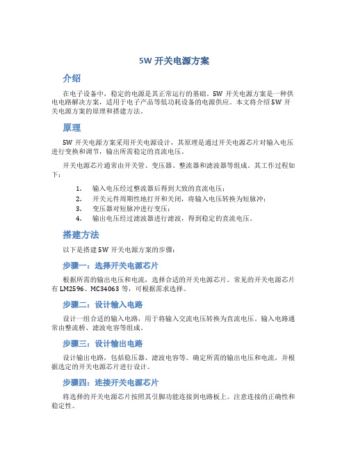
原理5W开关电源方案采用开关电源设计,其原理是通过开关电源芯片对输入电压进行变换和调节,输出所需稳定的直流电压。
开关电源芯片通常由开关管、变压器、整流器和滤波器等组成。
其工作过程如下:1.输入电压经过整流器后得到大致的直流电压;2.开关元件周期性地打开和关闭,将输入电压转换为短脉冲;3.变压器对短脉冲进行变压;4.输出电压经过滤波器进行滤波,得到稳定的直流电压。
搭建方法以下是搭建5W开关电源方案的步骤:步骤一:选择开关电源芯片根据所需的输出电压和电流,选择合适的开关电源芯片。
常见的开关电源芯片有LM2596、MC34063等,可根据需求选择。
步骤二:设计输入电路设计一组合适的输入电路,用于将输入交流电压转换为直流电压。
输入电路通常由整流桥、滤波电容等组成。
步骤三:设计输出电路设计输出电路,包括稳压器、滤波电容等。
确定所需的输出电压和电流,并根据选定的开关电源芯片进行设计。
步骤四:连接开关电源芯片将选择的开关电源芯片按照其引脚功能连接到电路板上。
注意连接的正确性和稳定性。
步骤五:调节输出电压连接所有元件之后,通过调节开关电源芯片上的调节电位器,可以调节输出电压达到所需的稳定值。
使用注意事项在搭建5W开关电源方案时,需要注意以下事项:1.输入电压范围:确保开关电源方案能够适应所需的输入电压范围。
2.输出电压、电流:合理选择开关电源芯片和其他元件,确保输出电压和电流符合需求。
3.散热问题:开关电源芯片工作时会产生一定热量,要注意散热设计,避免过热损坏电源。
4.过流保护:开关电源芯片通常会具有过流保护功能,需要合理设置并测试。
总结5W开关电源方案是一种有效的供电解决方案,适用于低功耗设备的电源供应。
本文介绍了5W开关电源方案的原理和搭建方法,并提供了使用注意事项。
零电压反激式开关电源芯片IRIS4015原理及设计要点

零电压反激式开关电源芯片IRIS4015原理及设计要点1.引言目前单片开关稳压电源有多种多样,如TOP-switch、Tiny- switch、Cool-set 等,这些单片开关稳压电源均工作在硬开关状态,开关损耗和EMI 较大。
为克服硬开关的缺点可用软开关工作方式。
在反激式开关电源中以无损耗缓冲电路和准谐振工作方式最为简单,而且准谐振工作方式可以实现零电压的开通和关断,在各种准谐振的解决方案中IRIS4015 是一种很好的方案。
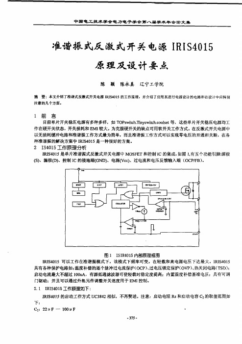
2. IS4015 工作原理分析IRIS4015 是单片准谐振式反激式开关电源中MOSFET 和控制IC 的集成,如图1,有五个功能引脚:源极(S)、漏极(D)、控制IC 的接地端(GND)、电源(Vcc)、过电流和电压反馈输入端(OCP/FB)。
IRIS4015 可以工作在准谐振模式下,该模式下频率可变,在轻载和高电源电压下达最大。
IRIS4015 具有各种保护电路如:温度补偿的逐个脉冲过电流保护(OCP)、过电压锁定保护(OVP)、热关闭电路(TSD);启动电流最大不超过100uA,有源低通滤波器可使轻载时稳定度提高;内置温度补偿基准电压;具有可调门驱动;并且可以通过外部元件调整开关速度用于EMI 控制。
2.1IRIS4015 工作原理IRIS4015 的启动工作方式UC3842 相似,不再赘述。
注意:启动电阻Rs 和启动电容C2 的取值范围如下:C2:22μF—100μF Rs:47KΩ—68KΩ(输入电压110 伏),82KΩ—150KΩ(输入电压220 伏)反馈和控制电路工作,振荡器和限流控制方式。
振荡器利用IC 中C2 的充放电产生脉冲信号确定MOSFET 的关断时间,如图2,这是IC 在没有电压控制反馈时,振荡器的工作过程。
当MOSFET 导通时,内置C1 被充电到约5.6V,漏极电流ID 流过R5 产生压降VR5(其波形为ID 的锯齿波),VR5 被反馈到OCP/FB 端来控制初级电流(初级电感电流控制方式),当OCP/FB 端电压达到门限电压Vth(1)(0.73V)时,比较器1 改变状态,振荡器输出关断信号,。
IR IRS2548D 40V

IR IRS2548D 40V-1.4A 带PFC LED驱动解决方案开发板白皮书样片申请原器件配套视频培训在线座谈交流讨论IR公司的IRS2548D是带PFC LED驱动器和半桥控制器,是全集成全保护的600V LED或开关电源(SMPS)控制集成电路,把PFC,系统控制和半桥驱动器集成在一起,可编程PFC过流保护,微功耗250uA起动,可变频率振荡器,主要用在隔离的LED驱动器和开关电源.本文介绍了IRS2548D主要特性,方框图, PFC控制电路框图和典型应用电路图以及40V/1.4A低压LED驱动器参考设计电路图,电感元件指标和材料清单.IRS2548D: SMPS/LED DRIVER PFC + HALF-BRIDGE CONTROL ICThe IRS2548D is a fully integrated, fully protected 600V LED or switched mode power supply control IC with integrated PFC control for a Boost pre-regulator. The IRS2548D is based on the popular IRS2168D electronic ballast control IC re-designed for use in LED driver or half-bridge power supply applications. The PFC circuitry operates in critical conduction mode and provides high PF, low THD and DC bus regulation. The IRS2548D features include programmable minimum run frequency and adjustable oscillator frequency that can be driven by an opto isolator or other feedback circuit in a feedback loop for frequency modulation in resonant systems. The IRS2548D also includes PFC over-voltage and over-current protection, half bridge over current protection and a logic level enable input that can be used for PWM dimming in LED drivers or general burst mode operation.IRS2548D主要特性:PFC, system control and half-bridge driver in one ICCritical-conduction mode boost-type PFCProgrammable PFC over-current protectionHalf Bridge DriverHalf Bridge Over Current ProtectionVariable Frequency OscillatorFixed internal 1.6us HO and LO deadtime Internal bootstrap MOSFETInternal 15.6V zener clamp diode on Vcc Micropower startup (250uA)Latch immunity and ESD protectionIRS2548D典型应用:Isolated LED DriversPower Supplies图1.IRS2548D方框图图2.IRS2548D PFC控制电路框图图3.IRS2548D典型应用电路图采用IRS2548D 40V/1.4A低压LED驱动器Solid state light sources are now available that offer viable alternatives to Fluorescent andHID lamps and far surpass incandescent lamps. Luminous efficacy expressed in Lumens per Watt has now reached levels enabling LEDs to be used for general illumination. High brightness LEDs also possess the added advantages of longer operating life span up to 50000 hours and greater robustness than other less efficient light sources making them suitable for outside applications such as street lighting.High power LEDs are ideally driven with constant regulated DC current, requiring a "driver" or "converter" to provide the required current from an AC or DC power source. A two stage power converter based around the IRS2548D PFC plus half bridge LED driver IC provides a controlled current output over a wide AC line voltage input range with high power factor and low THD.The IRPLLED5 evaluation board is an off line isolated low voltage / high output current LED driver designed to supply a 1.4A regulated DC output current over a voltage range of 30V to 60V operating from an AC line input voltage between 90 and 305VAC 50/60Hz. It also includes 1-10V dimming capability from 0 to 100% of light output. The outputs of this LED driver are fully protected against short circuit and limit the open circuit voltage to below 60VDC for safety compliance.图4.40V/1.4A低压LED驱动器外形图图5. IRPLLED5(40V/1.4A低压LED驱动器)方框图图6.IRPLLED5电路图(1)图7.IRPLLED5电路图(2)图8.IRPLLED5电路图(3)图9.IRPLLED5电路图(4)图10.IRPLLED5 PFC电感指标图图11.IRPLLED5 变压器指标图图12.IRPLLED5 反激电感指标图材料清单(BOM):详情请见:/product-info/datasheets/data/irs2548dspbf.pdf 和/technical-info/refdesigns/irplled5.pdf。
IRIRS2795(1,2)240W电源解决方案
IRIRS2795(1,2)240W电源解决方案IR公司的IRS2795(1,2)是LLC谐振半桥转换器控制集成电路,最高工作频率500kHz,可编程最低和最高开关频率,可编程软起动频率和时间以及死区时间,微功耗起动和超低静态电流,具有多种保护电路,用不着在LCD和PDP TV,通信和PC开关电源以及家庭音响系统.本文介绍了IRS2795(1,2)主要特性,方框图, 典型应用电路图以及IRS27951 240W评估板主要指标,电路图和材料清单与PCB布局图.The IRS2795(1,2) is a self oscillating half-bridge driver IC for DC-DC resonant converter applications, especially the LLC resonant half-bridge converter. The frequency and dead time can be programmed externally using two external components. The IC offers over current protection using the on state resistance of the low-side MOSFET. The IC can be disabled by externally pulling the voltage at the CT/SD pin below its enable voltage threshold.IRS2795(1,2)主要特性: Simple primary-side control solution for fixed and variable frequency DC-DC resonant converters. Max 500kHz per channel output with 50% duty cycle Floating channel bootstrap operation up to +600Vdc Programmable minimum and maximum switching frequency Programmable soft start frequency and soft start time Programmable dead time Micropower start-up & ultra low quiescent current Over-current protection using low side MOSFET Rds(on) User initiated micropower “Sleep mode” Under-voltage Lockout Simple design with minimal component count. Lead-freeIRS2795(1,2)典型应用: LCD & PDP TV Telecom SMPS, PC SMPS Home Audio Systems图 1.IRS2795(1,2)方框图图2.IRS2795(1,2)典型应用电路图IRS27951评估板This document details the test procedure for validation of IRAC27951SR-240W Evaluation Board, featuring the IRS27951 Resonant Half Bridge controller and the IR11682 dual-channel synchronous rectification controller. The document includes schematic diagram, test setup, test procedure, and test results.图3.IRS27951评估板外形图IRS27951评估板主要指标:图4.IRS27951评估板电路图IRS27951评估板材料清单:图5.IRS27951评估板用变压器电路图图 6.IRS27951评估板PCB布局图:上,顶层;下:底层详情请见:/product-info/datasheets/data/irs27951s.pdf和/technical-info/refdesigns/irac27951sr-240w.pdf。
开关电源检修方法综述(DOC)
开关电源检修方法综述开关电源简述:以下全是本人自编,难免错漏,见笑。
开关电源从激励方式来看,有自激和它激两种。
还有一个分类形式--串联和并联,串联电路已完全淘汰,没必要再研究它了。
其中自激电路比较有代表性的大家也很熟悉的是A3电源,它激的基本都是电源模块或者用一个小集成块驱动开关管。
模块的代表电路有STR-S6709/STR6656等,独立集成块驱动开关管的有TEA2261、TDA4605等.新机型已经出现了很多模块,几乎都是它激式了。
单块模块基本都是它激电路,也有自激的,比如6309。
自激电路基本构成:自激电路的实质其实就是一个单管自激振荡电路,加入脉宽控制电路和稳压取样电路就成了最基本的开关电源,当然,实际电路还要加入必要的过流过压保护。
自激振荡电路的调整方式除了脉冲宽度调整外,还有一个方式--调频,调频电路比较复杂,已经落伍,基本不用。
我见过的机型好像有:德律风根,***,都是一些欧洲品牌。
自激振荡电路有两个最基本的元件:一个电阻(约20-47欧)和一个电容串联,正是它们将开关变压器某绕组的脉冲信号反馈到三极管基极,以维持三极管的稳定振荡状态。
它激电路构成:它激电路因电路形式比较复杂,用分离元件来实现是不现实的,而集成电路的优势恰恰是能将复杂的多元件电路集成到一个芯片之中,所以它激电路最适合模块,自激电路中各种大容量(相对的,1UF已经大得不得了啦)电容较多,反倒难以集成化,也难以开发出新型号模块。
它激模块的特征更明显,振荡源是需要工作电压的,这个电压当然要滤波、稳压,还要从整流主电源上获得启动电压,启动后自动从开关变压器获取电源维持稳定工作。
不管自激或者它激,必然有一个能承受高压脉冲的开关管。
在自激电路中通常都是普通三极管(NPN)。
场效应管相对来说能承受更大的功率和温度而体积可以稍微小一点,因此,新出现的电源模块大多数都是集成了场效应管。
以上谈到的是常见CRT电视机的开关电源,不包括电脑主机电源、液晶等离子电视机电源。
IRS27951:240WAC-DC电源解决方案

IR公司的IRS27951/2是自振荡半桥驱动器,特别适用于LLC谐振DC-DC转换器应用。器件提供过流保护,每路工作频率最高为500kHz,可编程软起动时间和频率以及死区时间,主要应用在LCD和PDP TV,电信和PC开关电源,家庭音频系统。IRS2795(1/2)是一款用于DC-DC谐振转换器的自振荡半桥驱动器IC,特别适用于LLC谐振半桥转换器。通过采用两个外部元件,使其频率和死区时间可以进行外部编程。该IC采用低边MOSFET的通态电阻提供过电流保护。通过外部的CT/SD引脚将电压下拉使其低于使能电压阈值,该IC即可以停止工作。图1 IRS27951/2方框图图2 IRS27951/2典型应用电路图IRS27951/2主要特性•简单的初级控制解决方案,用于固定和可变频率的DC-DC谐振变换器•每通道最大500kHz的输出,占空比为50%•自举工作通道浮动电压最高可达600V•可编程最小和最大开关频率•可编程软启动频率和软启动时间•可编程死区时间•微功率启动和超低静态电流•采用低边MOSFET Rds(on)的过流保护•用户启动的微功耗“睡眠模式”•欠压闭锁•设计简单,元件数量少•无铅IRS27951/2应用• LCD和PDP电视•电讯开关电源,电脑开关电源•家庭音响系统图3 IRS27951评估板电路图图4 IRS27951评估板PCB布局图(顶层)IRS27951评估板用于IRAC27951SR-240W评估板该具有IRS27951谐振半桥控制器和IR11682双通道同步整流控制器。该评估板包括一个前端AC-DC整流级,并与一个具有24V输出电压轨的半桥谐振DCDC转换器级联。前端是一个常规的带有整流桥和EMI滤波器的整流器级。下行转换器是一个多谐振半桥LLC转换器,其由IRS27951(U1)控制器HVIC控制。该控制器驱动两个半桥MOSFET,有死区时间并且有50%的固定占空比,可根据反馈信号来改变频率,以针对负载和输入电压的变化来调节输出电压。如前所述,除了电流保护,所有控制谐振转换器设计所需的关键功能,可以使用其8引脚控制器IC进行外部编程。在C电容(CDC2和CVcc1)充电时,启动电阻Rstart1~Rstart3为IRS27951提供启动电流。一旦Vcc电压超过Vccuv+阈值,IRS27951开始工作并且电源变压器的辅助绕组给IC提供偏置。当24V负载从0A~10A变化时,辅助绕组的电压可能会有很大变化,因此,采用一个线性稳压器(包括 DZ4,Rvcc和Q2)将VCC保持在14.5V。变压器采用磁集成法,在变压器上集成了谐振系列和并联电感。变压器次级绕组的配置选择是中心抽头式。反馈回路是一个经典配置,采用了TL431(U3)来调整光耦TLP621(U2)的电流。光耦晶体管通过调整控制器IC引脚上RT的电流来调节开关频率,从而实现输出电压的调节。次级整流由同步整流控制器IR11682和两个PQFN功率MOSFET来实现。每个输出脚使用一个IRFH5006和一个60V MOSFET(导通电阻典型值3.5mohm)。使用同步整流大大降低了传导功率损耗。10A的连续输出电流不需要散热片。采用高度集成的双通道SmartRectifierTM控制器IR11682,也节省了PCB的面积。同步整流电路连接在低边配置中。所以,IR11682可直接驱动两个SR MOSFET。一个RCD电路添加到IR11682 VD的感应输入上,用以提供前沿滤波器和关断延迟补偿。通过一个简单的线性稳压器Q1(一般NPN晶体管)和齐纳二极管Dz2(12V)将R11682 偏置到24V。此外,第二个齐纳二极管Dz3(9.1V)是用来防止输出电压很低时同步整流电路被激活。当输出电压接近18V时,IR11682将开始运作。
准谐振式反激式开关电源IRIS4015原理及设计要点
嚣
口 J 压居 月遨 泪
图 1 I 05 I R 1 内部原理框图 S4 II 05可以 RS 1 4 工作在准谐振模式下,该模式下频率可变, 在轻载和高电 源电 压下达最大。 RS05 II 1 4 具有各种保护电 路如: 温度补偿的 逐个脉冲过电 流保护( C )过电 O P 压锁定保护( V )热关闭电 T D ; 、 O P、 路(S ) 启动电流最大不超过 10A 有源低通滤波器可使轻载时稳定 0u , 度提高;内 置温度补偿基准电 压; 具有可调 门驱动;并且可以 通过外部元件调整开关速度用于E I M 控制。 21 I41工作原理如下: . RS05 I II 05 启动Z作方式 U 34 相似, RS 1 的 4 C 82 不再赘述。 注意: 启动电 s 阻R 和启动电 C 的 容 Z 取值范围如
下:
C ; u 10 F : 2 F一 0 u 2
-7 3 5-
一 一 一 遗. & - 经* A 一 一 一 xl 艺 Af - kt i 竺 }
R : 。 一 6K ( s 4K 7 8 I 输入电 1 伏) Z 压 1 0
8K。 一 5K 输入电压 20 10 S ( 2 2 2 伏)
ON it Ca t l W dh nr a
图4 次级电压控制对脉冲宽度的影响 23 准谐振工作方式的分析 . 准谐振方式是在 V S D最小情况下的清 况下,由 初级线圈电 感和一个缓冲电容器提供一个控制 M SE O F T开 通 的谐振信号,以降低开关损耗。在这种工作模式下的O P B将高于V () 4V 最大6 ) C/ F t 2 =. h 15 V ,当 这个电 压维持在V ()以上时, O F T m 1 M SE 保持关断状态 ( 注意: 准谐振信号最小持续时f u) 此, 7I 。因 s 准谐振模式下的谐振频率的一半周期用来使M SE O FT导通。漏极和源极之间的 谐振电容C 与变压器初级 3 电 感形成谐振电路, 在控制绕组D与 O P B端加一个由C, C/ F 3 马、 , R 组成的 延迟电 路产生准谐振信号, 在M SE 截止时控制比较器2 O FT 并触发准谐振方式。
海尔L32R1液晶电源工作原理详解与故障检修

海尔L32R1液晶电源工作原理详解与故障检修是家电维修同行就会将您加进群,我们有维修群,制冷电器行业群,电器销售商群,净水器行业群,电器配件商群,或者长按二维码加群主微信导读:海尔L32Rl液晶电视电源送出的电压为+5V、+12V和+24V三组,其中5V为待机电压,给主板待机电路供电,12V给主板供电,24V给背光板电源板工作电路原理图如下图所示。
海尔L32Rl液晶电视电源送出的电压为+5V、+12V和+24V三组,其中5V为待机电压,给主板待机电路供电,12V给主板供电,24V给背光板供电。
1.待机电路启动过程电源板接通市电,220V经C6、LF2、VR1、C3、C5、C4、LF1、Ll滤波,再经BD1整流、Cl滤波后,得到+310V直流电,分两路分别经Tl和T3变压器初级加到V2的“D”极、待机电源芯片U3(NCP1014AP65G)的(5)脚。
撇开主电源电路暂且不说,单说U3待机电源芯片,U3的(5)脚得电后,芯片内置启动电路首先给E6充电,当E6电压上升到7.5V左右时.U3内部振荡电路开始振荡进入工作状态,U3工作后,在T3变压器初级辅助绕组产生12V、15V两组直流电压.12V为U3工作提供二次供电,维持振荡;15V接三极管V9(C1008)c极。
V9受开/关机控制电路控制实现对主电源Ul供电控制。
T3变压器次级产生+5V/0.7A电压给主板控制电路(按键处理、遥控信号处理、开/关机处理等电路J供电。
D8、C27、R40为尖峰吸收电路,抑制开关管在关时产生的尖峰脉冲损坏U3内开关管。
2、5V待机电压稳压+5V电压经R115、R116分压至U7(TL431)(1)脚参考电压输入端,通过内部电路控制电压输出。
U7工作特点是(1)脚电压升高,(3)脚电压降低。
通过Ul0控制U3(4)脚电压,调整芯片内置PWM发生器占空比,迫使次级输出电压稳定。
3.主电源电路启动过程主板收到开机信号时,主板输出的开/待机控制电压(+5V)经CON3接插件(7)脚加到Vll(9014)b极,使c极电位拉低,U9(PC817)光耦得电导通,15V 经R30、U9次级加到V9(C1008)b极,使V9导通。
开关电源的原理与设计

随着电力电子技术的发展和新型功率元器件的不断出现,开关电源技术得到了飞速的发展,在计算机、通讯、电力、家用电器、航空航天等领域得到广泛应用,取得了显著的成果。
本论文是通过用电源控制芯片M51995AFP设计并制作一种开关电源,该开关电源是通过PWM技术控制开关的占空比来调整输出电压的,以达到稳定输出的目的。
论文主要完成的内容有:(1)根据设计需要选择开关电源电路;(2)设计输入整流滤波电路,并确定相关器件参数;(3)基于M51995AFP对开关电源的控制核心部分进行设计;(4)设计输出整流滤波电路,并确定相关器件参数;(5)设计电压反馈电路;(6)通过实验和计算对设计中的数据进行验证。
本论文对开关电源的滤波、整流、反馈电路等分别作了细致的研究工作,通过实验和计算,掌握了开关电源设计的核心技术,并对设计过程进行了详尽的阐述。
关键词:开关电源;占空比;PWMWith the development of the electronic technology and the emerging of new power components, switching power supply has been widely used in computer, communications, electricity, home appliances and aerospace fields, achieving remarkable results.The purpose of this papers is to design and make a switching power supply based on control chip M51995AFP and PWM Control. This switching power supply could adjust the output voltage by using the duty cycle of PWM Control. Stable output purposes could be attained.The main content of the papers are:(1)Choose switching power supply circuit based on the requirement;(2)Design input rectifier filter circuit and identify the relevant device parameters;(3)Design the core control parts of switching power supply based on M51995AFP;(4)Design rectifier output filter circuit and establish the relevant device parameters;(5)Design voltage feedback circuit;(6)Validate data of the designing by adoption of experimental and computations.In the thesis , the switching power supply filtering, rectifier and the feedback circuit are studied in details. The main technology of designing switching power supply is obtained by experiments and calculations. The design process is specified also.Key words: Switching Power Supply; Duty cycle; PWM目录1.绪论 (1)1.1 开关电源的概念和分类 (1)1.1.1开关电源的概念 (1)1.1.2开关电源的分类 (3)1.2 开关电源设计中存在的问题与未来发展 (4)1.2.1开关电源中存在的问题 (4)1.2.2开关电源的发展趋势 (5)2.开关电源元器件的选用 (6)2.1 开关晶体管 (6)2.1.1功率开关MOSFET (6)2.1.2 绝缘栅双极型晶体管 (7)2.2 软磁铁氧体磁芯 (8)2.2.1磁性材料的基本特性 (9)2.2.2磁芯的结构与选用 (9)2.3 光电耦合器 (10)2.4 二极管 (12)2.4.1开关二极管 (13)2.4.2稳压二极管 (13)2.4.3快速恢复及超快速恢复二极管 (14)2.5 自动恢复开关 (14)2.6 热敏电阻 (15)3.开关电源的设计基础 (17)3.1 开关电源的控制方式 (17)3.1.1脉宽调制的基本原理 (17)3.1.2脉冲频率调制的基本原理 (18)3.2 各类拓扑结构电源分析 (19)3.3 谐振式电源与软开关技术 (24)3.3.1电路的谐振现象 (24)3.3.2谐振式电源的基本原理 (25)3.3.3谐振开关的动态过程分析 (26)3.3.4软开关技术及常见软开关拓扑简介 (30)3.4 其它软开关技术应用及发展概况 (36)4.开关电源设计 (38)4.1 开关电源集成控制芯片 (38)4.1.1芯片管脚排列及说明 (38)4.1.2芯片基本特性 (39)4.1.3芯片工作原理分析 (40)4.2 开关电源电路分析 (47)4.2.1开关电源电路原理图 (47)4.2.2开关电源各单元电路具体分析 (49)结论 (55)致谢 (56)参考文献.................................................................................................................- 57 -1.绪论开关电源是近年来应用非常广泛的一种新式电源,它具有体积小、重量轻、耗能低、使用方便等优点,在邮电通信、航空航天、仪器仪表、工业设备、医疗器械、家用电器等领域应用效果显著。
ZL2008:3A数字电源解决方案

电路板 , 具有 1 5安培 同步 降压转换器 。
・
・
Z 2 0 应 用 L08
・
排序 ,跟 踪 ,裕 度 ,和 其他 功能 ,都 负载阶跃 d/t25 S) i =. d A, 可 以通过此评估板进行评估 。 更 多 详 情, 敬 请 浏 览 : S u MB s适配 器板 上的 U B可 用 h t / S0 I i e C Cn . , S t P: / U t n. CO m O
Z 2 0 :3 字 电源解 决 方案 L 0 8 A数
Itri公 司 的 Z 2 0 nes l L 0 8是 数
字 D / C 电 源 控 制 器 ,集 成 了 3 CD A
MOS E F T驱动 器 , 流特性允 许多个 均
器件并联 连接给 负载供 电以满足 更高
电 流 的 需 求 。输 入 电压 3 ~ 1 V, V 4
输 出 电压 O6 V ~ 55 .4 .V,输 出 电压 精 度 ±1 %,并 具 有 快 速 负 载 瞬 态
响 应 。集成 了和 P u MB s兼 容 的 I C/
SMB S接 口 ,主 要 用 在 服 务器 / U 存 储器 设备 、通信 / 数据 通信 设 备以及
电源模块 。
电 源转 换
・
・
快 速负载瞬态响应 电流共 享和相交 织
高效同步降压控制器 自适应轻载效率优化 3 ~ 1 V的输入范围 V 4
・
・
与 主机 控 制 器 的 通信 ,以及 Dii 1 gt . a
・
・ n p h tM S a s o 参数捕获 T ・ o S兼 容 ( mmx6 Rl 6 mm)Q N圭 装 F 十
atx开关电源工作原理与维修实例

atx开关电源工作原理与维修实例1、ATX开关电源工作原理与修理实例开关电源工作原理与修理实例来源:时间:2021-05-17:apolloATX是计算机的工作电源,作用是把沟通220V的电源转换为计算机内部使用的直流5V,12V,24V的电源。
本文对ATX电源的组成及工作原理做了具体的讲解,最终并附上ATX电源修理实例供大家参考,盼望对大家解决ATX电源故障问题有所关心。
ATX型电源电路的组成及工作原理型电源电路的组成及工作原理ATX开关电源,电路按其组胜利能分为:沟通输入整流滤波电路、脉冲半桥功率变换电路、帮助电源电路、脉宽调制掌握电路、PS-ON和PW-OK产生电2、路、自动稳压与爱护掌握电路、多路直流稳压输出电路。
请参照图1和ATX电源电路原理图。
1.PS-ON和PW-OK、脉宽调制电路PS-ON信号掌握IC1的4脚死区电压,待机时,主板启闭掌握电路的电子开关断开,PS-ON信号高电3.6V,IC10精密稳压电路WL431的Ur电位上升,Uk电位下降,Q7导通,稳压5V通过Q7的e、c极,R80、D25和D40送入IC1的4脚,当4脚电压超过3V时,封锁8、11脚的调制脉宽输出,使T2推动变压器、T1主电源开关变压器停振,停止提供+3.3V、5V、12V的输出电压。
受控启动后,PS-ON信号由主板启闭掌握电路的电子3、开关接地,IC10的Ur为零电位,Uk电位升至+5V,Q7截止,c极为零电位,IC1的4脚低电平,允许8、11脚输出脉宽调制信号。
IC1的输出方式掌握端13脚接稳压5V,脉宽调制器为并联推挽式输出,8、11脚输出相位差180度的脉宽调制掌握信号,输出频率为IC1的5、6脚外接定时阻容元件的振荡频率的一半,掌握Q3、Q4的c极所接T2推动变压器初级绕组的激励振荡,T2次级它激振荡产生的感应电势作用于T1主电源开关变压器的一次绕组,二次绕组的感应电势经整流形成+3.3V、5V、12V的输出电压。
LN5S21 LN5S21A LN5S21B力生美SR同步整流设计方案

LN5S21A、LN5S21B描述LN5S21A 是一颗内置MOSFET 的高性能的开关电源次级侧同步整流功率开关集成电路,可以方便地在应用中构建满足CoC V5 及DoE 2016 等6级能效的5V/9V/12V 2.4A~3A 电流级别的快速充电开关电源系统,是性能优异的理想二极管整流器解决方案。
芯片内置了独特的TrueWave TM 全时波形追踪技术,可支持高达200kHz 的开关频率应用,并且支持CCM/CrM/DCM 等各种开关电源工作LN5S21B 是一颗内置MOSFET 的高性能的开关电源次级侧同步整流功率开关集成电路,可以方便地在应用中构建满足CoC V5 及DoE 2016 等6级能效的5~20V 电压范围3~3.5A 电流级别的快速充电开关电源系统,是性能优异的理想二极管整流器解决方案。
芯片内置了独特的TrueWave TM 全时波形追踪技术,可支持高达200kHz 的开关频率应用,并且支持CCM/CrM/DCM 等各种开关电源工作模式应用,可在开关电源的每一个波形转换的边沿自动快速打开或关闭内部的Low RdsON MOSFET器件,利用其极低的导通压降实现远小于诸如肖特基二极管的导通损耗,极大提高了系统的转换效率,大幅降低了整流器件的温度,可方便地实现极高转换效率的低压大电流的开关电源应用。
模式应用,可在开关电源的每一个波形转换的边沿主要特点自动快速打开或关闭内部的Low RdsON MOSFET 器u内置TrueWave TM 实时波形追踪技术件,利用其极低的导通压降实现远小于诸如肖特基u极佳的5V/9V/12V 快充同步整流二极管的导通损耗,极大提高了系统的转换效率,u支持开关电源CCM/CrM/DCM 模式大幅降低了整流器件的温度,可方便地实现极高转u内置NMOSFET V DS 耐压高达105V换效率的低压大电流的开关电源应用。
u内置NMOSFET RdsON 低至10mΩ芯片内置耐压高达105V 的NMOSFET 同步整流u比传统二极管整流效率提高3~6%功率开关,且具有极低的内阻,典型RdsON 低至u极宽的工作电压范围4V 至40V10mΩ,可提供系统高达3A 电流输出能力,获得优异的转换效能,大幅提高转换效率。
电脑开关电源维修GG图解及原理图解

电脑开关电源维修图解一颗强劲的CPU可以带着我们在复杂的数码世界里飞速狂奔,一块最酷的显示卡会带着我们在绚丽的3D世界里领略那五光十色的震撼,一块最棒的声卡更能带领我们进入那美妙的音乐殿堂。
相对于CPU,显示卡、声卡而言,电源可能是微不足道的,我们对它的了解也不是很多,可是我们必须知道,一个稳定工作的电源,是使我们计算机能够更好工作的前提。
计算机开关电源工作电压较高,通过的电流较大,又工作在有自感电动势的状态下,因GHGGHGHFHHHF F此,使用过程中故障率较高。
对于电源产生的故障,不少朋友束手无策,其实,只要有一点电子电路知识,就可以轻松的维修电源。
首先,我们要知道计算机开关电源的工作原理。
电源先将高电压交流电(220V)通过全桥二极管(图1、2)整流以后成为高电压的脉冲直流电,再经过电容滤波(图3)以后成为高压直流电。
此时,控制电路控制大功率开关三极管将高压直流电按照一定的高频频率分批送到高频变压器的初级(图4)。
接着,把从次级线圈输出的降压后的高频低压交流电通过整流滤波转换为能使电脑工作的低电压强电流的直流电。
其中,控制电路是必不可少的部分。
它能有效的监控输出端的电压值,并向功率开关三极管发出信号控制电压上下调整的幅度。
在计算机开关电源中,由于电源输入部分工作在高电压、大电流的状态下,故障率最高;其次输出直流部分的整流二极管、保护二极管、大功率开关三极管较易损坏;再就是脉宽调制器TL494的4脚电压是保护电路的关键测试点。
通过对多台电源的维修,总结出了对付电源常见故障的方法。
一、在断电情况下,“望、闻、问、切”由于检修电源要接触到220V高压电,人体一旦接触36V以上的电压就有生命危险。
因此,在有可能的条件下,尽量先检查一下在断电状态下有无明显的短路、元器件损坏故障。
首先,打开电源的外壳,检查保险丝(图5)是否熔断,再观察电源的内部情况,如果发现电源的PCB板上元件破裂,则应重点检查此元件,一般来讲这是出现故障的主要原因;闻一下电源内部是否有糊味,检查是否有烧焦的元器件;问一下电源损坏的经过,是否对电源进行违规的操作,这一点对于维修任何设备都是必须的。
lrs开关电源工作原理

lrs开关电源工作原理
LRS开关电源,是指低压电源(Low Range Switching Power Supply)的缩写,它是一种常见的电源供应器件,主要用于工业控制、通信设备、医疗设备等领域。
LRS开关电源的工作原理涉及到多个方面,我将从不同角度来解释。
首先,LRS开关电源的工作原理涉及到输入和输出电路。
在输入电路方面,交流电源首先经过整流和滤波,将交流电转换为直流电。
然后,直流电进入开关电源的输入端,经过输入滤波电路进行滤波处理,保证电源的稳定性和纹波小。
在输出电路方面,经过开关电源内部的开关元件(如MOS管)进行高频开关,通过变压器进行变压变换,最终得到需要的输出电压。
其次,LRS开关电源的工作原理还涉及到控制电路。
开关电源内部有一个控制电路,它可以根据输出电压的变化情况来控制开关元件的导通和关断,以调整输出电压的稳定性和精度。
控制电路通常采用反馈控制,通过采样电路获取输出电压信息,再经过比较和调节,控制开关元件的工作状态,实现稳定的输出电压。
此外,LRS开关电源的工作原理还涉及到保护电路。
在实际应
用中,为了保护电源和负载,LRS开关电源通常会内置过压保护、过流保护、短路保护等功能。
当电源或负载出现异常情况时,保护电路会及时采取措施,保护设备不受损坏。
总的来说,LRS开关电源的工作原理涉及到输入输出电路、控制电路和保护电路等多个方面,通过精密的设计和合理的控制,实现对输入电压的稳定转换和对输出负载的可靠供电。
希望以上解释可以全面地回答你的问题。
NXP TEA152x STARplug Mini开关电源解决方案
关键词:电源管理,AC/DC转换器,开关电源,SMPS,STARplug Mini,
NXP公司的TEA152x系列是低功耗系统的开关电源控制IC,采用高压EZ-HV SOI工艺和BiCMOS工艺制造,包括高压功率开关和直接从火线电压整流的起动电路,通用电源功率高达30W,火线电压从80 V到276 V,待机功耗低于100mW,主要用在充电器,适配器,STB,DVD,TV/监视器待机电源和PC外设.本文介绍了TEA152x主要特性和优势,方框图以及STARplug Mini演示板主要特性和多种配置电路图与相应的元件列表.TEA152x:SMPS ICs for low-power systemsThe TEA152x family STARplug is a Switched Mode Power Supply (SMPS) controller IC that operates directly from the rectified universal mains. It is implemented in the high-voltage EZ-HV SOI process, bined with a low-voltage Bipolar plementary Metal-Oxide Semiconductor (BiCMOS) process. The device includes a high-voltage power switch and a circuit for start-up directly from the rectified mains voltage.A dedicated circuit for valley switching is built in, which makes a very efficient slim-line electronic power-plug concept possible.In its most basic version of application, the TEA152x family acts as a voltage source.Here, no additional secondary electronics are required. A bined voltage and current source can be realized with minimum costs for external ponents. Implementation of the TEA152x family renders an efficient and low cost power supply system.TEA152x主要特性和优势: Designed for general purpose supplies up to 30 W Integrated power switch: TEA1520x: 48 Ω; 650 V TEA1521x: 24 Ω; 650 V TEA1522x: 12 Ω; 650 V TEA1523P: 6.5 Ω; 650 V Operates from universal AC mains supplies (80 V to 276 V) Adjustable frequency for flexible design RC oscillator for load insensitive regulation loop constant Valley switching for minimum switch-on loss Frequency reduction at low power output makes low standby power possible (< 100 mW) Adjustable overcurrent protection Undervoltage protection Temperature protection Short-circuit winding protection Simple application with both primary and secondary (opto) feedback Available in DIP8 and SO14 packagesTEA152x应用: Chargers Adapters Set-Top Box (STB) DVD CD(R) TV/monitor standby supplies PC peripherals Microcontroller supplies in home applications and small portable equipment, etc. 图1.TEA152x系列框图 图1.TEA152xP初级检测应用配置图STARplug Mini演示板The STARplug Mini Switched Mode Power Supply (SMPS) demo board es in two versions: a 5 V version and 12 V version. The circuit implemented on this board is typically suited to low-power adapter applications.The board has a universal mains input. The total nominal output power is rated at 3 W for the 5 V version and 5 W for the 12 V version. The flyback circuit is built around the NXPSemiconductors TEA1521T or TEA1522T STARplug IC. The STARplug Mini demo board allows customization of the input filtering, snubber circuit, regulation feedback scheme etc. Small changes in output voltage (up to20 %) are also supported. If an alternative transformer is considered, the Printed-Circuit Board (PCB) can generate virtually any output voltage. These features make the STARplug Mini demo board a highly versatile and reliable starting point for developing custom low-power boards.This versatility es at the cost of PCB space, so the board is not a showcase for minimal PCB space usage and cannot be looked upon as an end-solution. However, it is very useful for exploring the STARplug family of IC’s features and functionality during development of a low-power SMPS final solution.图1. STARplug Mini演示板主要特性:• Universal mains input• Isolated output• 5 V/3 W and 12 V/5 W version available as default configurations• Stable regulated voltage• Highly flexible and easily tuned to meet user requirements• Used with the TEA1520T, TEA1521T and TEA1522T devices (SO14 package)• Highly efficient: 5 V version > 68 %, 12 V version > 79 %• Low standby (no-load) power: < 80 mW• OverPower Protection (OPP)• OverTemperature Protection (OTP)• Built-in basic differential mode ElectroMagnetic Interference (EMI) filter. 图2.TEA152x演示演示板外形图 图2.TEA152x STARplug Mini默认配置图 图3.TEA152x带RCD缓冲器的STARplug Mini配置图 图4.TEA152x STARplug Mini初级反激配置图 图5.TEA152x STARplug Mini自供电配置图 图6.TEA152x简化次级反馈STARplug Mini配置图默认元件列表: 5V/3W和12V/5W版本 RCD缓冲器增加元件列表: 初级反馈增加元件列表: c:\iknow\docshare\data\cur_work\.aoelectronicsc:\iknow\docshare\data\cur_work\.aoelectronics\main.phpc:\iknow\docshare\data\cur_work\.aoelectronicsc:\iknow\docshare\data\cur_work\.aoelectronics自供电源TEA152x增加元件列表: 简化次级反馈增加元件列表:
IRS27951:240W AC-DC电源解决方案

IRS27951:240W AC-DC电源解决方案关键词:IR IRS27951 IRS27952 照明半桥驱动器LEDIR公司的IRS27951/2是自振荡半桥驱动器,特别适用于LLC谐振DC-DC转换器应用。
器件提供过流保护,每路工作频率最高为500kHz,可编程软起动时间和频率以及死区时间,主要应用在LCD和PDP TV,电信和PC开关电源,家庭音频系统。
IRS2795(1/2)是一款用于DC-DC谐振转换器的自振荡半桥驱动器IC,特别适用于LLC谐振半桥转换器。
通过采用两个外部元件,使其频率和死区时间可以进行外部编程。
该IC采用低边MOSFET的通态电阻提供过电流保护。
通过外部的CT/SD引脚将电压下拉使其低于使能电压阈值,该IC即可以停止工作。
图1 IRS27951/2方框图图2 IRS27951/2典型应用电路图IRS27951/2主要特性•简单的初级控制解决方案,用于固定和可变频率的DC-DC谐振变换器•每通道最大500kHz的输出,占空比为50%•自举工作通道浮动电压最高可达600V•可编程最小和最大开关频率•可编程软启动频率和软启动时间•可编程死区时间•微功率启动和超低静态电流•采用低边MOSFET Rds(on)的过流保护•用户启动的微功耗“睡眠模式”•欠压闭锁•设计简单,元件数量少•无铅IRS27951/2应用• LCD和PDP电视•电讯开关电源,电脑开关电源•家庭音响系统图3 IRS27951评估板电路图图4 IRS27951评估板PCB布局图(顶层)IRS27951评估板用于IRAC27951SR-240W评估板该具有IRS27951谐振半桥控制器和IR11682双通道同步整流控制器。
该评估板包括一个前端AC-DC整流级,并与一个具有24V输出电压轨的半桥谐振DCDC转换器级联。
前端是一个常规的带有整流桥和EMI滤波器的整流器级。
下行转换器是一个多谐振半桥LLC转换器,其由IRS27951(U1)控制器HVIC 控制。
ICE2A0565开关电源基础学习知识原理与维修

ICE2A0565开关电源原理与维修该集成电路具有完善的过压、过载过流、欠压、过热关闭保护和欠压锁定、自动重启动及低功耗待机等功能。
由ICE2A0565组成的开关电源还具有所需外围元件少、电路简洁的特点。
VP-806型DVD机未附电路原理图.笔者实绘该机电源电路原理如附图。
下面就对该电路作一简要分析。
一、电源的输入、启动及输出交流220V市电经电源开关SW.保险管Fl flrl A/250V1送到由L804、CX801组成的电源共模滤波器,一方面滤除电网中的高频干扰信号,另一方面抑制开关电源产生的高频开关干扰对电网的污染。
滤波后的220V交流电经D801~D804组成的桥式整流电路整流、C801滤波后.产生约300V的直流电压。
该电压一路经开关变压器初级L1绕组,加到U804(ICE2A0565)④、⑤脚,另一路经启动电阻R801.R803对C818充电,使U804⑦脚电压上升。
与此同时U804内部软启动电路对①脚外接的软启动时间常数电容C807充电。
当⑦脚电压上升到13.5V,同时①脚电压上升到5.3V时,内部各功能电路开始正常工作。
内部激励电路输出高频开关脉冲使场效应功率开关管处于正常的高频开关状态。
当电路起振后,只要⑦脚电压不低于8.5V,电路就将锁定在正常振荡状态,一旦电源工作后,⑦脚所需电流会增大,此时由启动电阻R801、R803所提供的电流无法继续满足⑦脚内部电路的电流要求.改由开关变压器上的L2绕组输出的脉冲电压经D811整流,通过R802限流及C818、C819滤波后所产生的直流电压为⑦脚供电.以满足⑦脚在正常工作时的供电要求。
电源工作后,开关变压器各次级输出高频脉冲电压.经各自的整流滤波电路后输出+5V、+12V及-12V三组电压。
其中+5V电压还经主板稳压电路稳压后得到3.3V电压为解压集成电路供电。
二、稳压控制过程稳压电路主要由U804、光电耦合器U802(PC817)、精密可调基准三端稳压器U803(PT431)以及取样电阻R813、R815等组成。
开关电源测试解决方案

开关电源测试解决方案方案介绍开关电源因其体积小、效率高,被普遍的应用到各类电子产品中,按转换方式可划分为AC-DC电源,要紧包括电源适配器、充电器,电源板,PC电源,工业电源等;和以模块电源为要紧应用的DC-DC电源,UPS为要紧应用的AC-AC 电源,逆变器为要紧应用的DC-AC电源。
开关电源质量直接阻碍电子产品的质量和性能。
与其他电子类产品不同,开关电源不仅包括输入参数,还包括输出参数,和时刻参数。
其中输入参数包括输入的电压、电流、功率、浪涌电流、失真度;输出参数包括输出的电压、电流、功率、效率、纹波、源效应、负载效应等;时刻参数包括输出上升、下降时刻、响应时刻和输出逻辑顺序。
除电源输入输出参数外,开关电源需要具有良好的电气平安特性。
由于开关电源测试的项目较多,检测时刻长,在生产线检测时,采取利用交流电源、功率测量仪和电子负载对未封装的电源进行初检,待封装后,进行电气平安检测和要紧特性的综合检测,为了提高效率,开关电源测试一样采纳多通道并行测试的自动测试系统。
艾诺仪器致力于成为电气电子行业测试解决方案提供商,集成公司优质的产品为开关电源测试提供精准、靠得住、高速、一致的测试解决方案,包括电气安规分析仪,交流测试电源,直流测试电源,功率分析仪,直流电子负载,和多通道并行的开关电源自动测试系统。
同时,可为客户提供开放式软件平台,方便用户自主构建测试流程和标准、编辑生成测试报告、远程测试数据监管等,实现测试的自动化、信息化、智能化。
应用领域充电器、适配器电源板、LED背光电源板LED驱动电源,照明灯具电源模块光伏组件光伏逆变器、风能逆变器、车载逆变器产品系列1、交流电子负载AN29系列交直流电子负载2、直流电源AN50系列程控直流电源AN51系列直流测试电源3、交流电源AN61系列交流测试电源4、电参数分析仪AN87500/ AN8721H交直流功率分析仪AN800305、开关电源自动测试系统AN80系列电源供给器自动测试系统AN8061适配器/充电器自动测试系统AN8063LED电源自动测试系统AN8065模块电源自动测试系统6、电气安规分析仪AN9637H平安性能综合分析仪。
- 1、下载文档前请自行甄别文档内容的完整性,平台不提供额外的编辑、内容补充、找答案等附加服务。
- 2、"仅部分预览"的文档,不可在线预览部分如存在完整性等问题,可反馈申请退款(可完整预览的文档不适用该条件!)。
- 3、如文档侵犯您的权益,请联系客服反馈,我们会尽快为您处理(人工客服工作时间:9:00-18:30)。
IRIRSW开关电源解决方案
IRIRS27951220W开关电源解决方案
ledledled by externally pulling the voltage at the CT/SD pin below its enable voltage threshold.IRS27951/2主要特性:· Simple primary-side control solution for fixed and variable frequency DC-DC resonant converters.· Max 500kHz per channel output with 50% duty cycle· Floating channel bootstrap operation up to +600Vdc· Programmable minimum and maximum switching frequency· Programmable soft start frequency and soft start time· Programmable dead time· Micropower start-up & ultra low quiescent current· Over-current protection using low side MOSFET Rds(on)· User initiated micropower “Sleep mode”· Under-voltage Lockout· Simple design with minimal component count.· Lead-freeIRS27951/2典型应用:· LCD & PDP TV· Telecom SMPS, PC SMPS· Home Audio Systems图1. IRS27951/2功能方框图图2. IRS27951/2典型应用电路图IRAC27951-220W IRS27951评估板The evaluation board consists of a front-end AC-DC rectifier stage cascaded with a half-bridge resonant DCDC converter with multiple output voltage rails (24V and 12V). The front end is a conventional rectifier stage with a rectifier bridge and an EMI filter.The downstream converter is a multi-resonant half bridge LLC converter whose control is implemented with the IRS27951 (U1) controller HVIC. The controller drives the two half-bridge MOSFETs with a 50 percent fixed duty cycle with dead-time, changing the frequency according to the feedback signal in order to regulate the output voltages against load and input voltage variations. As described earlier, in addition to current protection, all the critical functions needed to control resonant converter designs can be externally programmed using this 8 pin controller IC.The transformer uses the magnetic integration approach, incorporating the resonant series and shunt inductances in the power transformer. The transformer configuration chosen for the secondary winding is center-tap, and the output rectifiers are Schottky diodes. The feedback loop is implemented by means of a classical configuration using a TL431 (U3) to adjust the current in the optocoupler TLP621 (U2). Weighted resistive dividers from both voltages are summed at the reference node of the TL431 in order to achieve a better overall output voltage regulation. The optocoupler transistor modulates the current from the RT pin of the controller IC to modulate the switching frequency, thus achieving output voltage regulation.图3. IRAC27951 220W 评估板外形图IRAC27951 220W 评估板主要指标:图4.IRAC27951 220W 评估板电路图IRAC27951 220W 评估板材料清单:图5.IRAC27951 220W评估板PCB布局图(顶层)图 6.IRAC27951 220W评估板PCB布局图(底层)详情请见:/product-info/datasheets/data/irs27951s.pdf和/technical-info/refdesigns/irac27951-220w.pdf。